 Open Access Article
Creative Commons Attribution 3.0 Unported Licence
Hybrid photocathode based on a Ni molecular catalyst and Sb2Se3 for solar H2 production†
D. Alicia
Garcia-Osorio
a,
Thomas P.
Shalvey
a,
Liam
Banerji
a,
Khezar
Saeed
 ab,
Gaia
Neri‡
a,
Laurie J.
Phillips
a,
Oliver S.
Hutter
 ac,
Carla
Casadevall
 d,
Daniel
Antón-García
 d,
Erwin
Reisner
 d,
Jonathan D
Major
*a and
Alexander J
Cowan
 *a
*a
aStephenson Institute for Renewable Energy, University of Liverpool, L69 7ZF, UK. E-mail: acowan@liverpool.ac.uk
bDepartment of Chemistry, Aarhus University, Aarhus C 8000, Denmark
cDepartment of Mathematics, Physics and Electrical Engineering, Northumbria University, NE1 8ST, UK
dYusuf Hamied Department of Chemistry, University of Cambridge, CB2 1EW, UK
First published on 19th December 2022
Abstract
We report a H2 evolving hybrid photocathode based on Sb2Se3 and a precious metal free molecular catalyst. Through the use of a high surface area TiO2 scaffold, we successfully increased the Ni molecular catalyst loading from 7.08 ± 0.43 to 45.76 ± 0.81 nmol cm−2, achieving photocurrents of 1.3 mA cm−2 at 0 V vs. RHE, which is 81-fold higher than the device without the TiO2 mesoporous layer.
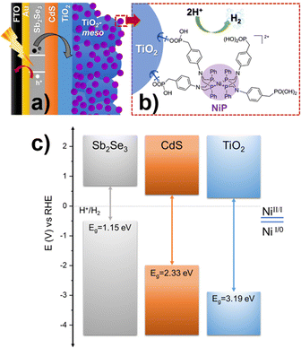
Photoelectrodes for the production of solar fuels, for example by splitting water to generate H2 and O2,1 have the potential to play a key role in future energy systems. However, advances in both photoanodes for water oxidation2 and photocathodes for hydrogen evolution (HER) are needed to improve the stability and to lower the cost for industrial scaling, since most long-lasting devices rely on precious metals.3–5 Sb2Se3 has recently gained interest from the photovoltaic (PV) community due to its near-direct band gap of 1.18 eV, a high absorption coefficient across the visible region,6 and an unusual 1D nanoribbon structure that enables effective charge transport.7 These properties, combined with improvements in material processability and the use of earth-abundant elements, have led to the suggestion that Sb2Se3 could be a viable thin film PV material for use on a global scale.8 Sb2Se3 has also been studied as a photocathode for HER, the conduction band minimum at −0.5 V vs. RHE provides enough driving force for producing H2,9 and its band gap (Eg) is very close to the optimal calculated for the bottom electrode in dual absorber standalone device for water splitting.10 Reported solar to hydrogen efficiencies, using state-of-the-art Sb2Se3 photocathodes, have now exceeded 10%.11,12 These photocathodes consist of a Sb2Se3/CdS buried junction that is coated with a protective TiO2 capping layer. The planar TiO2 is then modified with a HER catalyst like Pt,13,14 RuO2,12,15 and MoSx.16 Notably, even with state-of-the-art devices, reductive dissolution of TiO2 caused by photoelectron accumulation can occur.11,13 C60 between TiO2 and the H2-evolution catalyst can alleviate charge accumulation promoting the photoelectron transfer at the TiO2/Pt interface, but device stabilities are still low.11,13 Therefore, a need still exists to identify new active photoelectrode/catalysts systems that are able to keep up with the rate of photoelectron generation and to explore how the catalyst/TiO2 interface can be modified to prevent the generation of high-electron densities. Earth abundant molecular electrocatalysts have not previously been explored on Sb2Se3 photocathodes, even though they are an alternative to precious metal electrocatalysts and could potentially offer improved rates of charge transfer at the semiconductor/molecular catalyst interface.17,18 Here, NiP with a [Ni(P2R′N2R′′)2]2+ core (P2R′N2R′′ = bis(1,5-R′-diphospha-3,7-R′′-diazacyclooctane)), shown in Fig. 1b, was chosen as model molecular catalyst.19 The NiP catalyst mimics the hydrogenase intramolecular proton transfer to the Ni centre through the pendant amine groups in the second coordination sphere.20 Furthermore, it can be covalently anchored to TiO2 by the phosphonic acid groups in the outer coordination sphere, Fig. 1b.21
 | ||
| Fig. 1 (a) Schematic diagram of Sb2Se3/CdS/TiO2-meso/NiP hybrid photocathode. (b) Chemical structure of NiP catalyst molecular catalyst, panel a and b are not drawn to scale. (c) Equilibrium band alignment diagram of Sb2Se3/CdS/TiO2 heterojunction based on VBM11 and Eg measured separately for each layer (Fig. S2.1, ESI†), note that NiP redox couple is pH independent.21 | ||
The complete device FTO/Au/Sb2Se3/CdS/TiO2/TiO2-meso/NiP is shown in Fig. 1a. Sb2Se3 (1.5 μm) was deposited on Au (70 nm) coated fluorine-doped SnO2-glass (FTO) by a two-step fast-cooling close space sublimation process, which generates a compact preferentially orientated nanoribbon crystal structure that facilitates rapid hole transfer to the Au contact.7,11,12 Then, a thin sputtered CdS buffer layer (20 nm) was added which forms a Sb2Se3 heterojunction with a negligible conduction band offset, thereby allowing efficient charge separation and electron transfer towards TiO2 (Fig. 1c).6 In this way, the onset potential and fill factor of the Sb2Se3 photocathodes are improved despite the parasitic absorption of photons below λ < 500 nm in the CdS causing a decrease in the photocurrent.11,12 After, TiO2 (100 nm) was sputtered to provide a physical barrier preventing contact between the light absorber and the electrolyte.22 Full details of the synthetic procedures, the device characterisation and SEM images are provided in the ESI,† Fig. S2.1-3.
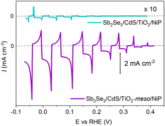
The molecular catalyst was first immobilized overnight onto the sputtered TiO2 (without the TiO2-meso) by soaking the photoelectrode in dry methanolic solution (0.5 mM NiP),19,23,24 and from now on labelled as Sb2Se3/CdS/TiO2/NiP. It was removed from the soaking solution, thoroughly washed in methanol to remove the non-chemisorbed catalyst and dried under vacuum. NiP loadings were determined by stripping the catalyst off using NaOH and then quantified by UV-vis spectroscopy, as shown in Table S1 (ESI†). When NiP was attached to the sputtered TiO2 layer, a loading of 7.08 ± 0.43 nmol cm−2 was achieved. All the photoelectrochemical tests were done under 100 mW cm−2 illumination (unless otherwise stated) and with λ > 340 nm in 0.1 M Na2SO4 at pH 3. pH 3 was chosen due to past studies that showed NiP was most active at this pH.23,25Fig. 2 shows a photocurrent of only −16 μA cm−2 at 0 V vs. RHE, which exceeds only slightly the current in the absence of any catalyst (−3 μA cm−2 for Sb2Se3/CdS/TiO2, Fig. S2.4, ESI†). The spikes in the light chopped Linear Sweep Voltammetry (LSV) of Sb2Se3/CdS/TiO2/NiP demonstrated that the photoelectrons are not being utilised at a fast-enough rate by the catalyst, instead recombination is dominating.26
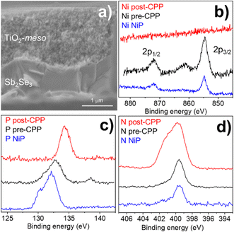
The low photocurrent of the Sb2Se3/CdS/TiO2/NiP electrode is due to the low loading of NiP compared with previous devices.23,24 A common approach to achieve higher catalyst loadings on a photoelectrode is to increase the available surface area for catalyst binding by using a mesoporous TiO2 layer (TiO2-meso). Typically, following deposition of a TiO2 nanoparticle-organic binder paste, thermal annealing is carried out in air (∼450 °C) to remove the binder and sinter the TiO2 nanoparticles forming conductive pathways.26 Sb2Se3 is unstable at these temperatures in air,8 therefore we modified a UV curing approach successfully developed by the Grätzel group for CuO2/AZO/TiO2 photocathodes.27 Following doctor blading of an anatase TiO2 paste (av. particle size 20 nm diameter) the sample was UV cured for 68 h using a 365 nm LED, Fig. S2.5 (ESI†). Note that the Sb2Se3/CdS/TiO2-meso also included the sputtered 100 nm TiO2 layer since it was found to be essential during the UV curing to protect the Sb2Se3/CdS. The photocathode was then annealed at lower temperature (350 °C) under N2 to improve the electrochemical properties of the TiO2-meso layer (Fig. S2.6-7, ESI†) without hindering the light absorber capabilities (Fig. S2.9, ESI†). The TiO2-meso was ca. 4–6 μm thick determined by profilometry, the cross-sectional image and energy-dispersive X-ray spectroscopy (EDX) maps are shown Fig. 3a and Fig. S2.10 (ESI†), respectively. Neither the UV curing nor the N2 annealing alone resulted in a TiO2-meso layer with electrical and mechanical features suitable for a molecular catalyst scaffold (Fig. S2.5 and S2.8, ESI†). The NiP immobilization on the TiO2-meso device was carried out using the same experimental protocol as for the planar structure. The resultant Sb2Se3/CdS/TiO2-meso/NiP photocathode achieved an increased NiP loading (45.76 ± 0.81 nmol cm−2), in line with the literature.24 Top view EDX mapping shows the catalyst is evenly distributed on the photocathode surface (Fig. S2.11, ESI†). X-Ray photoelectron spectroscopy (XPS) analysis of the NiP on the Sb2Se3/CdS/TiO2-meso/NiP electrode is shown in Fig. 3b–d. The energies of the Ni 2p (Fig. 3b, 1/2 at 872.1 eV and 3/4 at 854.6), P 2p (Fig. 3c, 132.6 eV) and N 1s (Fig. 3d, 399.6 eV) peaks are in good agreement with the NiP catalyst prior to immobilisation (all the XPS peak positions are shown in Table S2, ESI†).23–25 The complete Sb2Se3/CdS/TiO2-meso/NiP photocathode achieves a photocurrent of −1.3 mA cm−2 at 0 V vs. RHE with an onset potential of ca. +0.37 V vs. RHE (Fig. 2). The photocurrent for this electrode structure is amongst the highest reported for a NiP decorated photocathode, Table S3 (ESI†) provides the state-of-the-art hybrid photocathodes for H2 production. NiP has been previously used with a Si/TiO2-meso photocathode to achieve a photocurrent of −0.3 mA cm−2 at 0 V vs. RHE24 and −0.6 mA cm−2 at 0 V vs. RHE for a La5Ti2Cu0.9Ag0.1S5O7/TiO2 photocathode.23 A control experiment without the catalyst (Sb2Se3/CdS/TiO2-meso, Fig. S2.4. ESI†) demonstrates the importance of the NiP catalyst, it showed a photocurrent of only −0.12 mA cm−2 at 0 V vs. RHE. Incident photon to current efficiency (IPCE, Fig. S2.12, ESI†) demonstrates the device is active at wavelengths up to 900 nm (at 0 V vs. RHE), in-line with the Eg of Sb2Se3.6,7
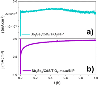
Controlled potential photoelectrolysis (CPP) carried out at 0 V vs. RHE assessed the stability of the Sb2Se3/CdS/TiO2-meso/NiP electrode, results shown in Fig. 4. The H2 faradaic efficiency after 1 h was 77.5 ± 9.1%, giving a TONNiP of 12.8 ± 2.8. However, the photocurrent decreased significantly in the first hour reaching −40 μA cm−2 and by 5 hours, it decreased to only −15 μA cm−2 (Fig. S2.13, ESI†). The loss of photoactivity of NiP photoelectrodes has previously been attributed to the hydrolysis of the phosphonic anchoring group from the TiO2.23,24 XPS analysis of the hybrid photocathode post CPP shows the loss of the Ni2+ bands (red trace, Fig. 3b). However, it is clear that both the N 1s and P 2p signals are still present, although significantly shifted. A broadening of the N 1s band has previously been assigned to protonation of the amine in the acidic electrolyte23 and the shifting of the P band is due to the loss of the metal centre.28 The XPS results suggest the phosphonate linkage has been retained but the Ni is no longer coordinated to the ligand, in-line with the stability of the phosphonate linkage at pH < 7.29 Past studies have shown that NiP degradation occurs on photocathodes but with a slower decay rate.23,24
 | ||
| Fig. 4 CPP at 0 V vs. RHE of the hybrid photocathodes Sb2Se3/CdS/TiO2/NiP (a) and Sb2Se3/CdS/TiO2-meso/NiP (b) in 0.1 M Na2SO4 pH 3 at 100 mW cm−2 and λ > 340 nm. | ||
To explore the mechanism of the hybrid photocathode decay here, we examined the TiO2-meso/NiP interface (without Sb2Se3/CdS). CPE at −0.24 V vs. RHE (Fig. S2.7b, ESI†), shows that following an initial drop in the current in the first 600 s, the electrode maintains a stable current of −0.24 mA cm−2 for 1 h suggesting that the TiO2-meso/NiP interface is stable at this potential and capable of dealing with low current density. However, the current spikes observed with Sb2Se3/CdS/TiO2-meso/NiP when the light is turned off in Fig. 2 are typical features of electron accumulation in the TiO2, suggesting that the NiP catalyst was unable to turnover at the rate of photoelectron generation under 100 mW cm−2 illumination. Based on the concentration of immobilised NiP (45.76 ± 0.81 nmol cm−2), and the highest reported turnover frequency of NiP (460 ± 5 h−1),21 we calculate that the NiP on the surface could support a photocurrent of −1.15 mA cm−2. This magnitude of photocurrent is achieved briefly in the LSV, but CPP shows the photocurrent decreases rapidly as the NiP catalyst degrades. To assess the photoelectron generation of Sb2Se3/CdS/TiO2-meso, we used Pt as co-catalyst (see ESI,† for synthetic details, Fig. S2.14). The Sb2Se3/CdS/TiO2-meso/Pt electrode achieved a stable photocurrent of −3 mA cm−2 at 0 V vs. RHE for 5 hours. It is clear that the rate of photoelectron generation at the Sb2Se3/CdS interface greatly exceeds the maximum current density that NiP can sustain. The catalytic mechanism of NiP is shown in Fig. S2.15 (ESI†),20 H2 production occurs following the NiII/I reduction. Further reduction from NiI to Ni0 can also potentially occur deactivating the catalyst if the rate of photoelectron generation is too high.30 To explore if limiting the photoelectron generation on the Sb2Se3 would be beneficial, experiments at 20 mW cm−2 (Fig S2.16 and S17, ESI†) were carried out. Notably, only a small decrease in photocurrent was observed from 1.30 to 0.81 mA cm−2 at 0 V vs. RHE, and 20% of photocurrent was retained after 1800 s compared with the 11% at 100 mW cm−2.
Past studies using precious metal HER catalysts like Pt on planar TiO2 coated Sb2Se3 photocathodes have noted that dissolution of TiO2 can also occur due to photoelectron accumulation.11,13 The SEM images post-CPP Sb2Se3/CdS/TiO2-meso/NiP electrodes (tested at 100 mW cm−2) did not show significant change in the morphology of the device (Fig. S2.18, ESI†) despite the demonstration of electron accumulation in the device. XRD analysis of a post-CPP sample only showed the typical peaks of Sb2Se3 and TiO2 (Fig. S2.19, ESI†) and no indication of Sb2O3 formation, which has been associated with the deactivation of the Sb2Se3 photoelectrodes (Fig. S2.20, ESI†).12,13 However experiments where Sb2Se3/CdS/TiO2-meso/NiP underwent (i) LSV and CPP at 0 V vs. RHE for 1 h, (ii) removal of any remaining NiP by NaOH stripping, and (iii) Pt addition and photoelectrochemical testing showed evidence of partial failure of the sputtered TiO2 layer due to photoelectron accumulation. Significantly higher dark currents (<−5 mA cm−2, Fig. S2.21, ESI†) and decreased photocurrents were measured compared to a pristine platinized photoelectrode, reinforcing the importance of preventing photoelectron accumulation in the Sb2Se3/CdS/TiO2-meso/NiP photocathode.
Emergent chalcogenide semiconductors such as Sb2Se3 are promising photocathodes due to their ability to achieve a high rate of photoelectron generation but they suffer from thermal instability limiting processing opportunities. Furthermore, Sb2Se3 interfaces need to be protected by metal oxide capping layers where corrosion could occur due to photoelectron accumulation. To prevent electron accumulation research has focused on the use of these absorbers with precious metal HER catalysts. Here we present an alternative approach using a Sb2Se3/CdS/TiO2-meso photocathode. The high surface area TiO2 support, prepared by a UV and low temperature N2 annealing process that is compatible with Sb2Se3, enables a high loading of an earth abundant molecular HER catalyst, NiP. An 81-fold increase in the photocurrent was achieved when compared to a similar device without the mesoporous TiO2. Despite the high catalyst loading, stability and activity under 100 mW cm−2 is still limited by the turnover frequency of the HER catalyst. However, initial experiments under low light intensities indicate that improved stability is achievable with further advances in the catalytic turnover frequency.
We thank the studentship financial support from CONACYT-SENER (556479, DAGO), EPSRC (DTA, DAG), the UKRI Cambridge Creative Circular Plastics Centre (EP/S025308, ER, CC), and the European Commission for Horizon 2020 Marie Skłodowska-Curie Individual Fellowships (890745-SmArtC, CC). EPSRC is acknowledged for funding though EP/P034497/1, EP/N014057/1 and EP/V011863/1. Prof L. Hardwick and Facility for XPS (“HarwellXPS”) are thanked for the Raman spectroscopy access and the XPS data collection (Contract No. PR16195).
Conflicts of interest
There are no conflicts to declare.Notes and references
- S. Ye, C. Ding, R. Chen, F. Fan, P. Fu, H. Yin, X. Wang, Z. Wang, P. Du and C. Li, J. Am. Chem. Soc., 2018, 140, 3250–3256 CrossRef CAS PubMed.
- S. Ye, C. Ding, M. Liu, A. Wang, Q. Huang and C. Li, Adv. Mater., 2019, 31, 1902069 CrossRef CAS PubMed.
- H. Song, S. Luo, H. Huang, B. Deng and J. Ye, ACS Energy Lett., 2022, 7, 1043–1065 CrossRef CAS.
- R. M. Irfan, D. Jiang, Z. Sun, L. Zhang, S. Cui and P. Du, J. Catal., 2017, 353, 274–285 CrossRef CAS.
- S. Ye, W. Shi, Y. Liu, D. Li, H. Yin, H. Chi, Y. Luo, N. Ta, F. Fan, X. Wang and C. Li, J. Am. Chem. Soc., 2021, 143, 12499–12508 CrossRef CAS PubMed.
- H. Shiel, O. S. Hutter, L. J. Phillips, J. E. N. Swallow, L. A. H. Jones, T. J. Featherstone, M. J. Smiles, P. K. Thakur, T. L. Lee, V. R. Dhanak, J. D. Major and T. D. Veal, ACS Appl. Energy Mater., 2020, 3, 11617–11626 CrossRef CAS.
- O. S. Hutter, L. J. Phillips, K. Durose and J. D. Major, Sol. Energy Mater. Sol. Cells, 2018, 188, 177–181 CrossRef CAS.
- A. Mavlonov, T. Razykov, F. Raziq, J. Gan, J. Chantana, Y. Kawano, T. Nishimura, H. Wei, A. Zakutayev, T. Minemoto, X. Zu, S. Li and L. Qiao, Sol. Energy, 2020, 201, 227–246 CrossRef CAS.
- S. Chen, T. Liu, Z. Zheng, M. Ishaq, G. Liang, P. Fan, T. Chen and J. Tang, J. Energy Chem., 2022, 67, 508–523 CrossRef CAS.
- B. A. Pinaud, J. D. Benck, L. C. Seitz, A. J. Forman, Z. Chen, T. G. Deutsch, B. D. James, K. N. Baum, G. N. Baum, S. Ardo, H. Wang, E. Miller and T. F. Jaramillo, Energy Environ. Sci., 2013, 6, 1983–2002 RSC.
- W. Yang, J. Park, H.-C. C. Kwon, O. S. Hutter, L. J. Phillips, J. Tan, H. Lee, J. Lee, S. D. Tilley, J. D. Major and J. Moon, Energy Environ. Sci., 2020, 13, 4362–4370 RSC.
- W. Yang, J. H. Kim, O. S. Hutter, L. J. Phillips, J. Tan, J. Park, H. Lee, J. D. Major, J. S. Lee and J. Moon, Nat. Commun., 2020, 11, 1–10 CrossRef PubMed.
- J. Tan, W. Yang, Y. Oh, H. Lee, J. Park, R. Boppella, J. Kim and J. Moon, Adv. Energy Mater., 2019, 1900179 CrossRef.
- J. Park, W. Yang, J. Tan, H. Lee, J. W. Yun, S. G. Shim, Y. S. Park and J. Moon, ACS Energy Lett., 2020, 5, 136–145 CrossRef CAS.
- W. Yang, S. Lee, H.-C. Kwon, J. Tan, H. Lee, J. Park, Y. Oh, H. Choi and J. Moon, ACS Nano, 2018, 12, 11088–11097 CrossRef CAS PubMed.
- R. R. Prabhakar, W. Septina, S. Siol, T. Moehl, R. Wick-Joliat and S. D. Tilley, J. Mater. Chem. A, 2017, 5, 23139–23145 RSC.
- F. Niu, D. Wang, F. Li, Y. Liu, S. Shen and T. J. Meyer, Adv. Energy Mater., 2019, 1900399 Search PubMed.
- W. Jiang, X. Yang, F. Li, Q. Zhang, S. Li, H. Tong, Y. Jiang and L. Xia, Chem. Commun., 2019, 55, 1414–1417 RSC.
- M. L. Helm, M. P. Stewart, R. M. Bullock, M. R. DuBois and D. L. DuBois, Science, 2011, 333, 863–866 CrossRef CAS PubMed.
- W. J. Shaw, M. L. Helm and D. L. du Bois, Biochim. Biophys. Acta, Bioenerg., 2013, 1827, 1123–1139 CrossRef CAS PubMed.
- M. A. Gross, A. Reynal, J. R. Durrant and E. Reisner, J. Am. Chem. Soc., 2014, 136, 356–366 CrossRef CAS PubMed.
- A. Paracchino, V. Laporte, K. Sivula, M. Grätzel and E. Thimsen, Nat. Mater., 2011, 10, 456–461 CrossRef CAS PubMed.
- T. E. Rosser, T. Hisatomi, S. Sun, D. Antón-García, T. Minegishi, E. Reisner and K. Domen, Chem. – Eur. J., 2018, 24, 18393–18397 CrossRef CAS PubMed.
- J. J. Leung, J. Warnan, D. H. Nam, J. Z. Zhang, J. Willkomm and E. Reisner, Chem. Sci., 2017, 8, 5172–5180 RSC.
- T. E. Rosser, M. A. Gross, Y. H. Lai and E. Reisner, Chem. Sci., 2016, 7, 4024–4035 RSC.
- T. Berger, D. Monllor-Satoca, M. Jankulovska, T. Lana-Villarreal and R. Gomez, ChemPhysChem, 2012, 13, 2824–2875 CrossRef CAS PubMed.
- M. Schreier, J. Luo, P. Gao, T. Moehl, M. T. Mayer and M. Grätzel, J. Am. Chem. Soc., 2016, 138, 1938–1946 CrossRef CAS PubMed.
- NIST X-ray Photoelectron Spectroscopy (XPS) Database, Version 3.5, https://srdata.nist.gov/xps/, accessed 26 July 2022.
- K. L. Materna, R. H. Crabtree and G. W. Brudvig, Chem. Soc. Rev., 2017, 46, 6099–6110 RSC.
- A. Ruff, S. Janke, J. Szczesny, S. Alsaoub, I. Ruff, W. Lubitz and W. Schuhmann, ACS Appl. Energy Mater., 2019, 2, 2921–2929 CrossRef CAS.
Footnotes |
| † Electronic supplementary information (ESI) available. See DOI: https://doi.org/10.1039/d2cc04810h |
| ‡ Current address: Enapter S.R.L, via di Lavoria 56/g, 56040 Pisa. |
| This journal is © The Royal Society of Chemistry 2023 |


