DOI:
10.1039/D3AY00100H
(Paper)
Anal. Methods, 2023,
15, 1765-1774
Ultrahigh-sensitivity multi-parameter tacrolimus solution detection based on an anchor planar millifluidic microwave biosensor†
Received
18th January 2023
, Accepted 21st February 2023
First published on 21st February 2023
Abstract
To detect drug concentration in tacrolimus solution, an anchor planar millifluidic microwave (APMM) biosensor is proposed. The millifluidic system integrated with the sensor enables accurate and efficient detection while eliminating interference caused by the fluidity of the tacrolimus sample. Different concentrations (10–500 ng mL−1) of the tacrolimus analyte were introduced into the millifluidic channel, where it completely interacts with the radio frequency patch electromagnetic field, thereby effectively and sensitively modifying the resonant frequency and amplitude of the transmission coefficient. Experimental results indicate that the sensor has an extremely low limit of detection (LoD) of 0.12 pg mL−1 and a frequency detection resolution (FDR) of 1.59 (MHz (ng mL−1)). The greater the FDR and the lower the LoD, the more the feasibility of a label-free biosensing method. Regression analysis revealed a strong linear correlation (R2 = 0.992) between the concentration of tacrolimus and the frequency difference of the two resonant peaks of APMM. In addition, the difference in the reflection coefficient between the two formants was measured and calculated, and a strong linear correlation (R2 = 0.998) was found between the difference and tacrolimus concentration. Five measurements were performed on each individual sample of tacrolimus to validate the biosensor's high repeatability. Consequently, the proposed biosensor is a potential candidate for the early detection of tacrolimus drug concentration levels in organ transplant recipients. This study presents a simple method for constructing microwave biosensors with high sensitivity and rapid response.
1. Introduction
Microwave sensor is an important technology with benefits, including label-free operation, non-invasive identification, low cost, broad application range, and high flexibility.1,2 A biosensor is a type of detecting instrument, which is sensitive to biological matter and converts its concentration into an electrical signal.3–5 In recent years, the application of radio frequency (RF) biosensors in biomedicine has garnered considerable interest among researchers.6–8 The main parameters of the tested samples are analyzed by measuring biological materials and aqueous solutions of inorganic substances under radio and microwave frequencies. The experimental results demonstrate that the sample's conductivity and dielectric constant will vary. For instance, Sharafadinzadeh et al. demonstrated the application of a microwave microfluidic sensor to determine the concentration of a methanol aqueous solution.9 Xue et al. used flexible microstrip sensors to detect water content and acid value in oil.10 Wang et al. detected glycerin aqueous solution and ethanol aqueous solution using a differential microwave sensor with microfluidic technology.11 Microwave biosensors provide an important measurement platform for harsh industrial environments and testing environments, allowing for the monitoring and control of various experimental processes, such as material characterization, environmental monitoring, and structural state monitoring.12–15 Moreover, these sensing devices are capable of passive sensing via radio frequency identification (RFID) platforms, which increases their applicability in the emerging Internet of Things (IoT) technologies.16,17
During the measurement process, microfluidic technology and RF biosensor are combined to achieve quantitative and stable testing to solve the problem of sample wastage and biological contamination. Microfluidic technology is a rapidly developing technology, which has the characteristics of miniaturization and integration.18,19 It can be used to detect very small amounts of liquid samples, such as 10−9–10−18 L.20 Microfluidics technology is characterized by its small volume, rapid analysis speed, automatic completion of the entire process of sample analysis, and increasing integration scale, allowing for the development of high-cost, compact, and one-time detection instruments.21–23 Currently, many effective detection technologies have been validated in microfluidic devices, including electrochemical methods,24 fluorescence detection methods,25 and RF sensing methods.26 For example, Xu et al. detected tumor-derived exosomes using a magnetic microfluidic chip;27 Peng et al. used online fluorescence derivatization flow injection in a microfluidic device for the detection of Cr(III) and Cr(VI) in water samples after solid-phase extraction;28 Liu et al. used a microfluidic RF biosensor to monitor cell growth.29 However, they have inherent limitations in terms of detection, including low sensitivity, high destructiveness, and high detection limits.
Organ transplantation is the most effective way to treat various end-stage organ diseases. The rejection of a transplanted organ is the main cause of failure of transplantation, and immunosuppressive therapy is the key to the success of organ transplantation. Tacrolimus (FK506) is one of the most commonly used calcineurin inhibitors, mainly used to combat organ transplantation rejection.30 After oral absorption, tacrolimus mainly binds to tacrolimus-binding protein in a prototype, acts on T cells, and plays an immunosuppressive role. However, the binding mode of tacrolimus to the tacrolimus-binding protein in red blood cells is non-linear; therefore, the whole blood concentration of tacrolimus should be measured in clinical treatment. At present, drug concentration monitoring methods mainly include chromatographic analysis31 and immunoassay. Immunoassays to monitor tacrolimus concentration can lead to unpredictable overestimation of true tacrolimus concentration due to cross-reactivity of metabolites accounting for up to 30%, and overestimation of true tacrolimus concentration is bound to affect clinical efficacy.32 In addition, the operation procedure of this method is complex and each link has time requirements, which leads to a long time limit for the final concentration measurement. Thus, there is an urgent need for a technique and equipment that can detect tacrolimus concentration quickly, simply, cheaply, and stably to improve the current detection instruments.
This paper proposes an anchor planar millifluidic microwave (APMM) biosensor for the accurate and quantitative detection of tacrolimus samples. The overall size of the APMM structure is 16.87 mm × 15.94 mm, and a sample with a volume of 1 μL is dropped into the millifluidic channel for detection to minimize the consumption of the sample. Since electromagnetic waves can easily penetrate the material, changes in the resonance frequency and transmission coefficient are effectively characterized by tacrolimus concentration when the APMM biosensor detects tacrolimus samples. The integration of a microwave biosensor and a millifluidic channel has the advantages of a very LoD and high sensitivity, as demonstrated by experimental data. This integration enables the detection of biological samples quantitatively and has the benefit of a very low LoD. Moreover, based on the regression analysis of the dual-frequency characteristics of the APMM biosensor, the results demonstrate a very strong linear correlation between the tacrolimus concentration and the two resonance peaks. The good repeatability and reusability of the proposed biosensor are validated by performing five measurements on each sample. Therefore, the proposed RF biosensor is a new method for the detection of tacrolimus concentration, with more economical and simple advantages, and would further promote the development of organ transplant operation so that more organ transplant patients can benefit.
2. Materials and methods
2.1 Microwave resonator design
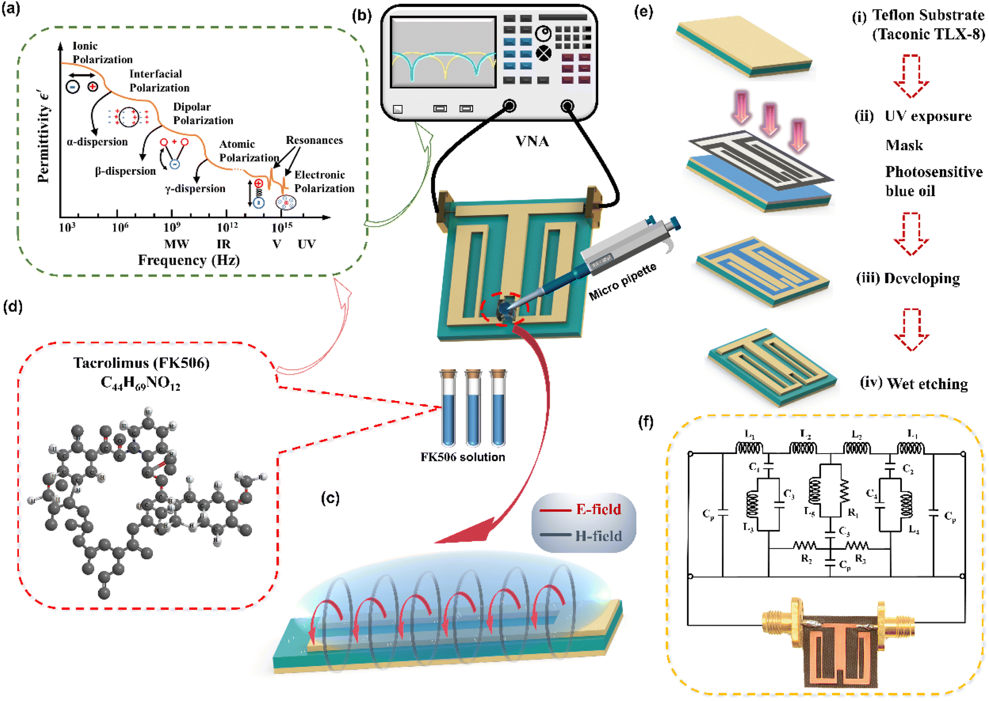
The schematic diagram of the symmetrical anchor planar millifluidic microwave (APMM) biosensor is depicted in Fig. 1. In the picture, the ginger yellow represents copper metal, while the dark green represents a Teflon substrate (Taconic TLX-8). The relevant dimensions of the APMM biosensor structure are shown in Table S1.†
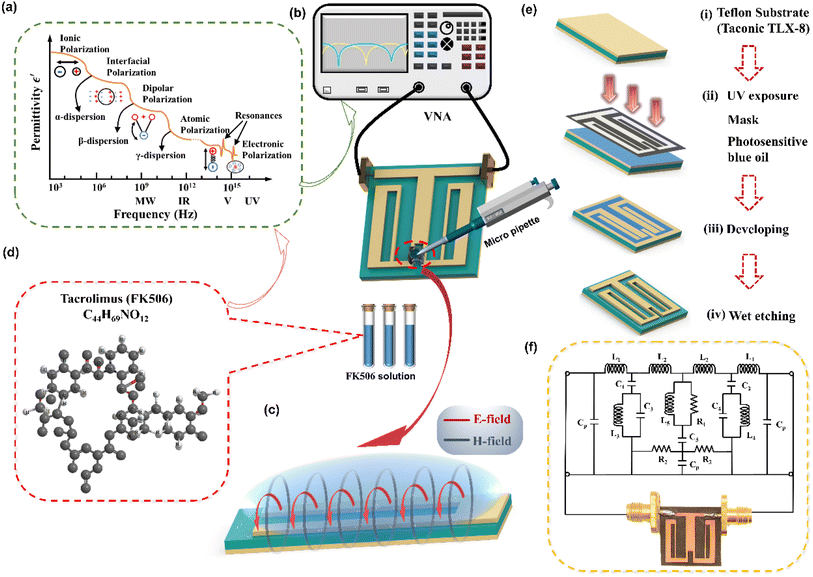 |
| | Fig. 1 Schematic diagram of the designed APMM biosensor. (a) Dielectric dispersion of the dielectric material in wide frequency spectra. (b) Schematic diagram of the proposed APMM sensor measurement system. (c) Mechanism of microwave transduction for microwave sensing with APMM electric field (E-field) and magnetic field (H-field) distribution. (d) Molecular structures for cluster models FK506 with atomic numbering. (e) Main fabrication process of APMM biosensor. (f) The equivalent circuit of the proposed sensor. | |
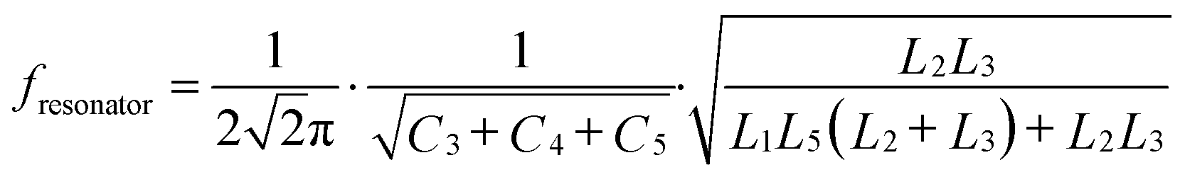
The resonator is modeled as a parallel RLC circuit, as shown in Fig. 1(f). Its capacitance is affected by the dielectric constant of the material under test (MUT) and the substrate itself, resulting in changes in the resonator's resonant frequency. The formula is as follows.
| |  | (1) |
C3 and
L3 represent the left wing, while their opposite the right wing are
C4 and
L4. The middle microstrip line is represented by
L5,
R1, and
C3, where
C3 represents the gap.
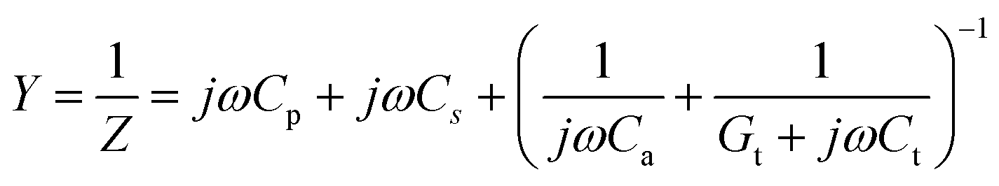
Equivalent admittance of capacitance is expressed as follows.33
| |  | (2) |
Cs and
Cp represent the capacitive effect of direct magnetic flux and magnetic flux through the substrate,
Ca is the effective capacitance of magnetic flux through air, and
Ct and
Gt represent magnetic flux through the tacrolimus sample capacitance and conductance, respectively. The net capacitance of APMM and tacrolimus sample can be expressed as follows.
Unit capacitance is expressed as
| |  | (4) |
where
k =
a/
b and
K(
k) are elliptic integrals of the first kind,
34N represents the number of units,
L is the coupling electrode length,
ε0 is the permittivity of free space,
εs is the dielectric constant of the substrate, and
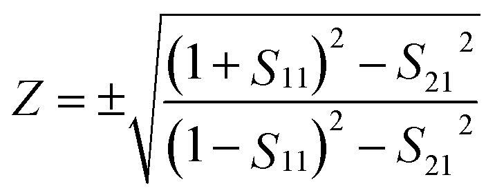
εt is the dielectric constant of the tacrolimus sample. Then, normalized impedance
Z and refractive index
n are evaluated from the measured
S parameters:
35| |  | (5) |
| |  | (6) |
where
k is the wave number,
k = 2π
f/
c (
c is the speed of light in a vacuum), and
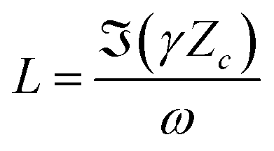
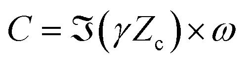
d is the propagation distance of the incident wave. Tacrolimus horizontal inductance (
L) and capacitance (
C) are calculated according to the measured propagation constant (
ϒ) and characteristic impedance (
Zc = 50 ×
Z), as shown in
eqn (7) and
(8)| |  | (7) |
| |  | (8) |
where
ω represents the angular frequency of the electromagnetic wave, and the propagation constant (
ϒ) can be expressed by the
S parameter.
36
2.2 The sensing mechanism
Under the action of an electric field, the positive and negative charges in a medium move in the opposite direction of the field, and this net charge separation is responsible for the conductivity. Under the action of an external electric field, the electrolyte will cause the relative displacement of valence electrons or nuclei, resulting in the redistribution of charge. This phenomenon is known as dielectric polarization. Five types of polarization mechanisms are observed when the medium is subjected to an alternating field of frequency transformation, first ionic polarization, then molecular polarization, and finally atomic polarization at very high frequencies (Fig. 1(a)). Understanding the interaction between electromagnetic waves and media, we are aware that the application of electric fields will result in the displacement of electric charges within the medium and the formation of dipoles. The conduction of charge in the dielectric generates a conduction current, whereas the displacement of charge due to polarization generates a displacement current. All electromagnetic wave sensors rely on detecting dielectric properties, also known as permittivity. However, optical biosensors only detect optical properties and not permittivity directly; thus, we introduce the rest into the frequency region from the RF to a few terahertz.
When the electric field is applied to the port of the microstrip line, a closed magnetic field will be generated around the microstrip line, and an electric field will be generated between the microstrip line and the substrate. In fact, electromagnetic energy exists as a time-varying electromagnetic field perpendicular to the surface of the flat open-loop resonator (Fig. 1(c)). Therefore, the solution sample dripping along the microstrip line will have an effect on the time-varying electromagnetic field surrounding the resonator, and this change will be displayed by the network analyzer.
2.3 Simulation and analysis
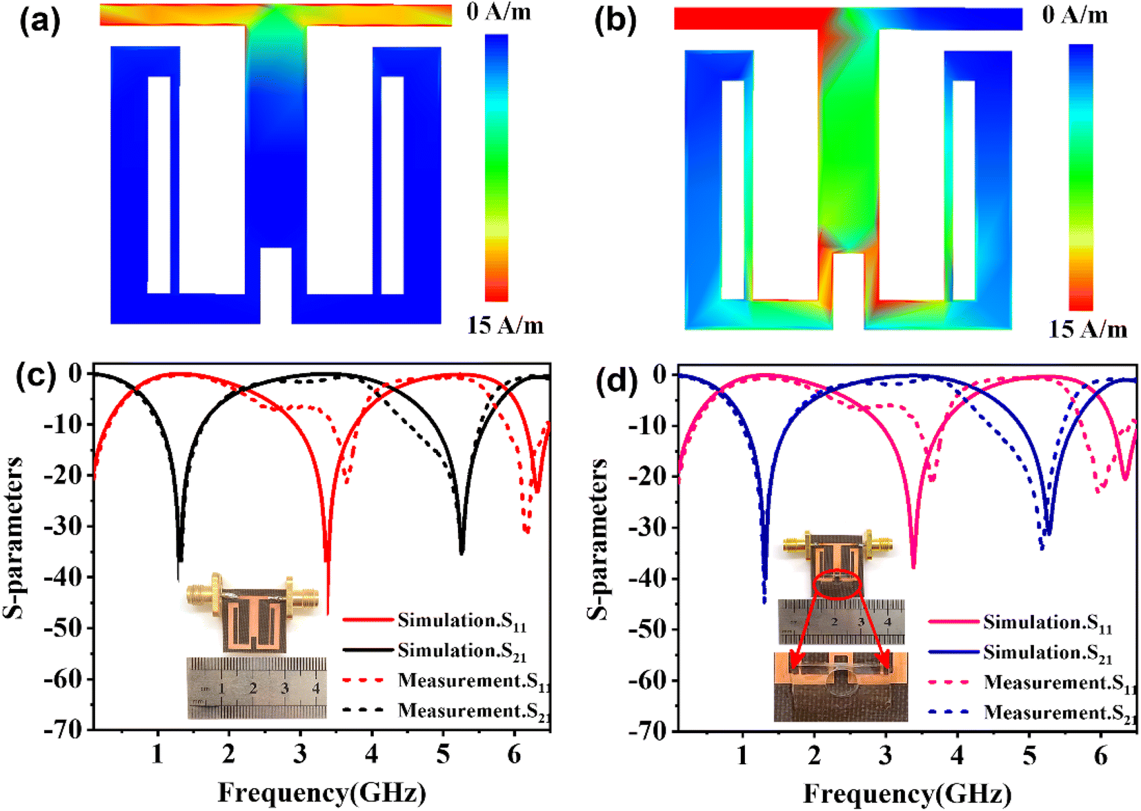
Considering the maximum frequency shift, machining limitation, and minimum alignment error, the millifluidic channel is aligned at the APMM biosensor's most sensitive detection position. To determine the location of the millifluidic channel on the APMM, electromagnetic simulation software (Advanced Design System, ADS) was used to calculate the sensor detection area. Fig. 2(a) and (b) depict the simulation results at 100 MHz and 1.308 GHz resonant frequencies, respectively. The region with the most intense electric field distribution has the highest sensitivity. The results show that the transmission profile (S21) of the sensor undergoes a frequency shift when the MUT is placed at the hot spot of the resonator. This displacement is the result of a change in the effective dielectric properties in the vicinity of the hot spot.
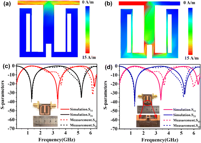 |
| | Fig. 2 Tangential electric field distribution of APMM at the resonant frequency of (a) 100 MHz and (b) 1.308 GHz. Simulated and measured S21 of the proposed APMM sensor (c) without and (d) with the PDMS millifluidic channels. | |
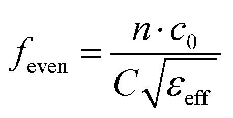
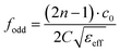
The reflection coefficient S21 of the APMM sensor can be observed in Fig. 2(c) and (d). Whether a PDMS millifluidic channel is present or not, the results of the ADS simulation are in good agreement with the measurements. After loading the PDMS millifluidic channel on the APMM sensor, although its resonant frequency and notch amplitude were reduced, this result had no effect on the MUT detection. For the transmission coefficients of various resonator harmonics, formula (11) can be used to express feven and fodd as37
| |  | (9) |
| |  | (10) |
where
C represents the length of the patch, and
εeff is the effective dielectric constant of the resonator environment. During the experiment, each sample influences the resonator capacitance by defining different effective dielectric constants, as shown in formula
(11), resulting in a variety of harmonic shifts. According to formulas
(9) and
(10), the relationship between the displacement of the
nth harmonic and the effective dielectric constant for even harmonics can be calculated using the following formula.
38| | 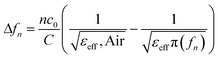 | (11) |
Considering the relative permittivity of air, if the relative permittivity of the sample is constant at the operating frequency, the nth harmonic frequency shift will be n times the fundamental frequency. To accomplish the measurement, the first and second harmonics are selected during data acquisition, and the effect of the change in dielectric constant on the harmonic frequency is considered. Fig. 2(c) and (d) depict the simulated and measured results of S21 for biosensors without and with millifluidic channels, respectively.
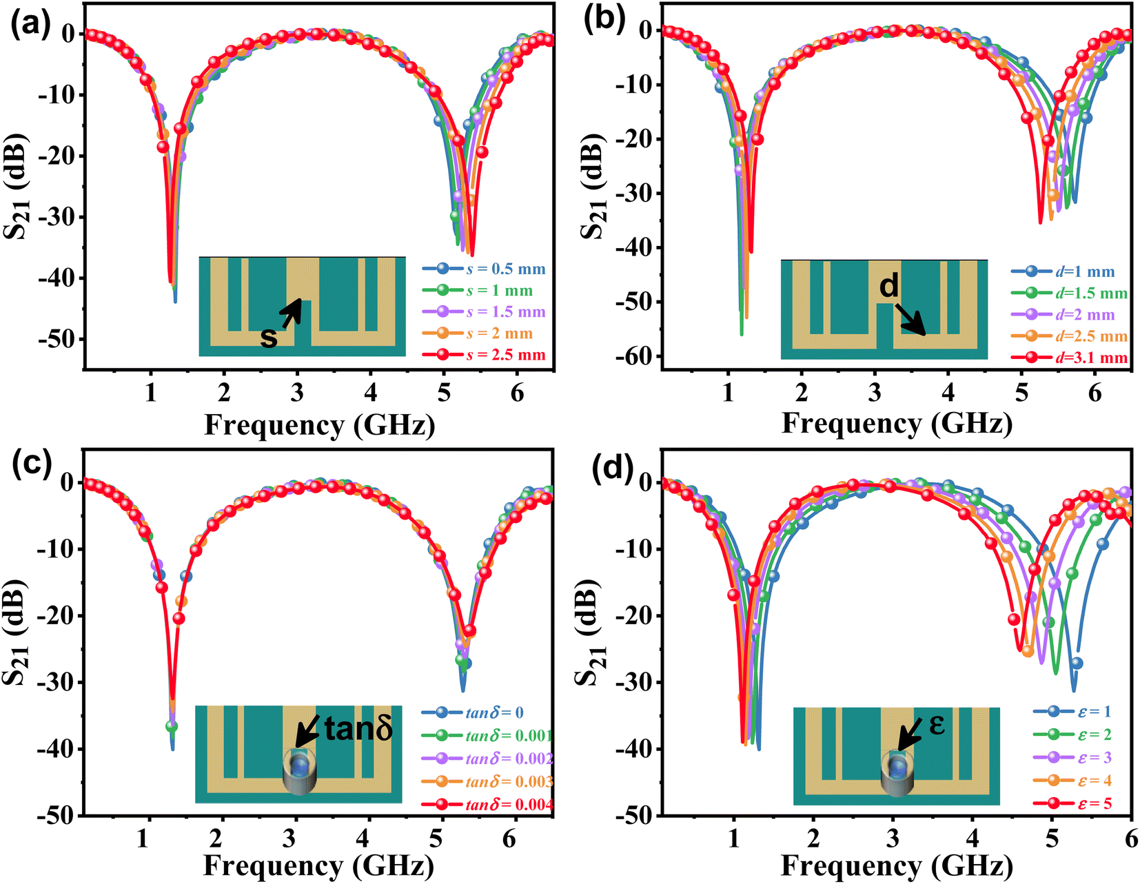
The effects of the length (d) and width (s) of the anchor plane microwave sensor gap on the frequency and S21 were investigated and are shown in Fig. 3(a) and (b). It has been found that these parameter changes have little effect on the odd mode but significantly alter the frequency shift of the even mode and the response of S21. To validate the sensing capability of the proposed APMM sensor, the MUT was placed within the measurement area and simulated using ADS software. When the dielectric constant is 1, the response of the resonator to the change of loss factor (tan![[thin space (1/6-em)]](https://www.rsc.org/images/entities/char_2009.gif) δ) is studied, as shown in Fig. 3(c). At the sensor's resonant frequency, when the loss factor is increased from 0.05 to 0.25 with a step size of 0.05, the absolute amplitude of S21 decreases significantly while the resonant frequency remains nearly unchanged. In addition, the dielectric constant (ε) of the variable MUT was also studied, whose ε varies from 1 to 5 with a step of 1, and the loss factor is considered to be 0.0019. As the dielectric constant rises, the simulation results reveal that the sensor's resonant frequency shifts to a low frequency in an obvious range. In addition, as shown in Fig. 3(d), the absolute amplitude of S21 decreases as the dielectric constant increases.
δ) is studied, as shown in Fig. 3(c). At the sensor's resonant frequency, when the loss factor is increased from 0.05 to 0.25 with a step size of 0.05, the absolute amplitude of S21 decreases significantly while the resonant frequency remains nearly unchanged. In addition, the dielectric constant (ε) of the variable MUT was also studied, whose ε varies from 1 to 5 with a step of 1, and the loss factor is considered to be 0.0019. As the dielectric constant rises, the simulation results reveal that the sensor's resonant frequency shifts to a low frequency in an obvious range. In addition, as shown in Fig. 3(d), the absolute amplitude of S21 decreases as the dielectric constant increases.
 |
| | Fig. 3 The simulated S21 of the APMM at different parameters of (a) s and (b) d. ADS simulation resonant profile of the sensor loaded MUT with varying (c) loss tangent and (d) permittivity. | |
2.4 Sensor fabrication and sample preparation
An anchor-shaped planar millifluidic microwave sensor was fabricated by chemical etching on a Teflon substrate (Taconic TLX-8) with a relative permittivity of 2.55 and a dielectric loss of 0.0019. The substrate had a thickness of 0.508 mm. On the substrate, a planar microwave sensor with a metal thickness of 0.07 mm was etched. The illustration of the proposed biosensor is shown in Fig. 1(e). The millifluidic system was prepared by PDMS solution and the detailed fabrication process is shown in Fig. S2.† The measurement setup and the parameters of the PDMS system are shown in Fig. S3.† The millifluidic system is artificially positioned on the underside of the APMM, where the edge electric field is the strongest, and as a result, it is most sensitive to changes in the dielectric properties. The PDMS millifluidic system ensures constant volume and sensing shape of liquid samples in the sensing region. It should be noted that the millifluidic position may influence the response of the RF biosensor. Although the resonance frequency and notch amplitude of the PDMS millifluidic are reduced after loading it onto the APMM sensor, simulations and measurements demonstrate that this has no impact on MUT detection.
For this experiment, 0.5 mg Astellas (Ireland) Procofotacrolimus capsules and 10 mL phosphate-buffered saline (PBS, pH = 7.2–7.4) produced by DaTech (Quanzhou) Co., Ltd. were prepared. The two substances were then combined and dissolved in a beaker that had been ultrasonically cleaned. To completely dissolve the powder into PBS, the beaker was placed on a magnetic stirrer and stirred for eight hours at 460 rpm. Next, 50 μg mL−1 tacrolimus stock solution was diluted with PBS solution. Finally, seven groups of samples were prepared and packaged separately, with the following concentrations: 10, 50, 100, 200, 300, 400, and 500 ng mL−1. The molecular formula of FK506 is shown in Fig. 1(d).
2.5 Microwave measurements
For measurement and experimental verification, the S parameters of the RF sensor were obtained using the Agilent E5071C Vector Network Analyzer (VNA). At ambient temperature (25 °C), the solution was dropped into the sensitive area of the millifluidic system of the sensor through a pipette gun during measurement. To investigate the sensitivity of the proposed anchor planar millifluidic microwave sensor, the S parameter value of a tacrolimus solution with a high concentration was measured. The surface morphology of the fabricated biosensor was measured by a scanning electron microscope (SEM, Tescan vega3, Czech Republic).
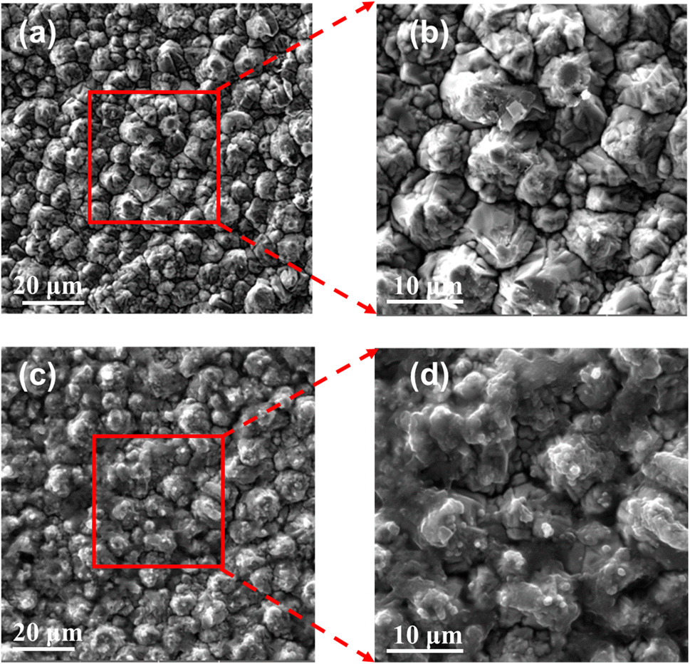
The morphology of the biosensors along with or without FK506 samples were characterized by SEM images, as shown in Fig. 4. The SEM images of the bare APMM biosensor are shown in Fig. 4(a). The enlarged SEM imaging (Fig. 4(b)) showed clean copper particles on the surface of the electrode before the FK506 sample was deposited. The SEM image of the biosensor with tacrolimus solution is shown in Fig. 4(c). It is demonstrated that the boundaries of the copper particles become blurred due to the deposition of FK506 solution. Moreover, smaller particles of FK506 can be found in the enlarged SEM image (Fig. 4(d)). Compared with the bare copper electrode, the electrode surface with samples presented a fuzzy and dusky state.
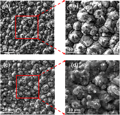 |
| | Fig. 4 The SEM images of (a) the bare chip and (b) the enlarged view of the selected area. The SEM images of the APMM biosensor deposited with the FK506 solution of (c) surface morphology and (d) the enlarged view of the selected area. | |
3. Results and discussion
3.1 Measurement results and analysis
For the tacrolimus solution concentration level detection sensor, the sample to be tested is placed in the position with the maximum current density to observe the corresponding frequency displacement change, and the frequency detection resolution (FDR) is expressed as39| |  | (12) |
where ΔC represents the change in sample concentration, and ΔF is the relative displacement of the resonance frequency. The concentration of tacrolimus solution increased from 10 ng mL−1 to 500 ng mL−1 (ΔC = 490 ng mL−1). The resonant frequency of the sensor changes from 1.138 GHz to 1.30 GHz (ΔF1 = 162 MHz) at the first formant. At the second formant, the resonant frequency changes from 4.160 GHz to 5.103 GHz (ΔF2 = 943 MHz). Therefore, the difference ΔF between the frequency changes of the two formant peaks is 781 MHz. Within the range of tacrolimus solution concentration (MHz (ng−1 mL)), the sensor's calculated sensitivity is 1.59. The greater the sensor's FDR value, the greater its sensitivity to sample concentration detection and resonance frequency change.
At present, the concentration of tacrolimus in clinical monitoring is different in different time periods after organ transplantation. Tacrolimus concentrations in early transplant patients approach homeostasis at 10–15 ng mL−1. In addition, for patients with post-transplantation or autoimmune diseases, the concentration requirements of tacrolimus in the maintenance period and stable period are relatively low; generally, 5–10 ng mL−1 can be basically maintained for a long time. Low detection of limit refers to the lowest amount of the tested substance in the sample that can be detected, which is used to indicate the lowest concentration detected by the determination method on the tested substance in the sample under the said conditions.
According to formula (13),40 the LoD of the proposed biosensor is 0.12 pg mL−1, demonstrating the sensor's extremely low detection limit. In addition, Table 1 provides a summary of the comparison between the proposed APMM biosensor and other published microwave sensors.
| |  | (13) |
where
K is 3 at 95% confidence level,
S0 represents the standard deviation, and
S is the slope of the calibration curve. The minimum detection limit of the APMM biosensor proposed in this paper is 0.12 pg mL
−1, which is consistent with the monitoring range of tacrolimus concentration after organ transplantation.
Table 1 Performance of the proposed sensor compared with previously reported methods
| Structure |
Specimen |
FDR (MHz (ng−1 ml)) |
LoD (pg ml−1) |
Millifluidic |
Ref. |
| Patch biosensor |
Glucose solution |
1.13 × 10⁻⁴ 1.97 × 10⁻⁴ |
26.54 × 10⁷ 15.22 × 10⁷ |
No |
41
|
| Radio-frequency (RF) biosensor |
Streptavidin and complementary DNA (cDNA) |
— |
1000 |
No |
42
|
| Microstrip patch sensor |
NaCl |
4.8 × 10⁻¹² |
\ |
No |
43
|
| SRR |
Prostate specific antigen (PSA) |
\ |
100 |
No |
44
|
| SRR |
Glucose solution |
8.89 × 10⁻⁷ |
— |
Yes |
45
|
| APMM |
Tacrolimus in aqueous solution |
1.59 |
0.12 |
Yes |
This work |
Fig. 5(a) illustrates the capacitance of the biosensor for samples with varying concentrations of tacrolimus. The inset picture demonstrates the capacitance peaks in the frequency range of 0.55–0.80 GHz. The capacitance of the formant is positively correlated with the concentration of the tacrolimus solution. When the tacrolimus concentration changes as 10, 50, 100, 200, 300, 400, and 500 ng mL−1, the net capacitance values at the cavity's center frequency were calculated to be 0.59, 0.37, 0.24, 0.19, 0.14, and 0.14 pF, respectively. As shown in Fig. 5(b), the inductance of the biosensor designed for various samples of tacrolimus exhibits formant peaks in the frequency range of approximately 1.1 to 1.5 GHz. The frequency and amplitude of the inductance peak are positively correlated with tacrolimus concentration. The inductance values at the center frequency of tacrolimus samples were 32.56, 46.04, 67.88, 75.79, 99.98, 105.66, and 115.57 nH. Therefore, the C and L at the resonant center frequency are proportional to the tacrolimus solution concentration. Fig. 5(c) and (d) depict the real and imaginary components of the sensor's admittance to different concentrations of tacrolimus samples. The inset pictures demonstrate the real and imaginary part of Y(1,1) peaks in the frequency range of 0.55–0.8 GHz. The admittance of the formant of the planar millifluidic microwave biosensor correlates positively with the concentration of tacrolimus solution.
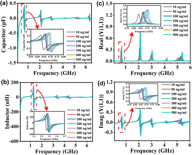 |
| | Fig. 5 Tacrolimus-level-dependent effective–medium parameters of the biosensor resonator for FK506. (a) Net capacitance (C), (b) net inductance (L), (c) real part of Y(1,1), and (d) imaginary part of Y(1,1). | |
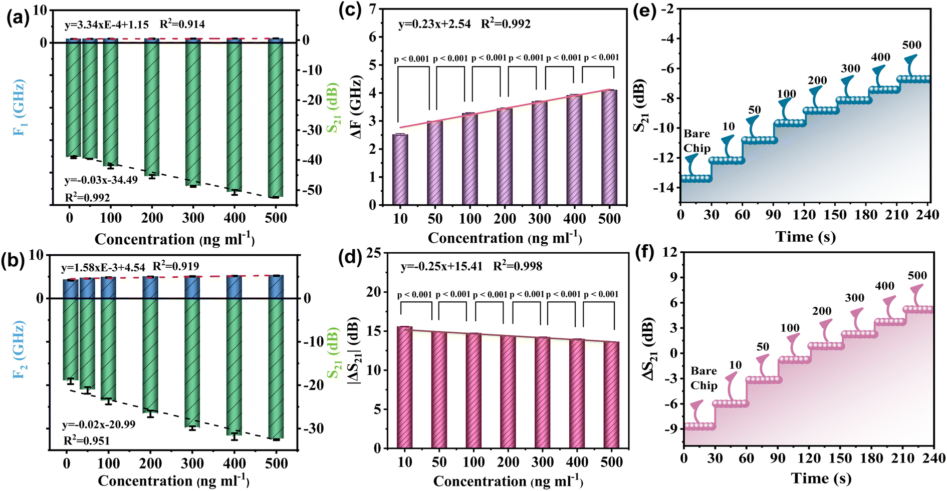
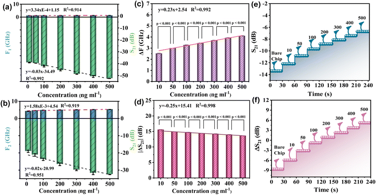
The linear relationship between the resonant frequency parameters F and S at the first resonant peak of the device and the concentration of the tested sample is depicted in Fig. 6(a). Among them, the coefficient (R2) of frequency F and concentration C is 0.914, and the linear correlation between the concentration and frequency of the device is relatively general. The linear relationship between the S parameter and the concentration of the tested sample was observed. The coefficient of determination (R2) of S21 and concentration C was 0.995. The device demonstrated an excellent linear correlation between concentration and S21. Next, the linear relationship between the resonant frequency F and S parameters of the device at the second resonant peak and the sample concentration was analyzed using Fig. 6(b). The determination coefficient (R2) of frequency F and concentration C is 0.919. Nonetheless, the linearity R2 between S21 and sample concentration C reached 0.951, and the device demonstrated a linear correlation between concentration and S21. The above analysis demonstrates that the linear correlation between the two formant parameters of the device is not ideal. Therefore, this paper proposes to calculate the linear correlation between the frequency changes of the two formant peaks of the RF device. Similarly, it also calculates the linear correlation between the ΔS21 of the two formant peaks, as shown in Fig. 6(c) and (d). Firstly, as shown in Fig. 6(c), the linear relationship between the difference of resonant frequency ΔF of the two peak values of the device and the concentration of the tested sample is observed. The determination coefficient (R2) of ΔF and concentration C is 0.992, indicating a good linear correlation. At the same time, the linearity (R2) between ΔS parameters and the concentration of the sample under test is increased to 0.998, indicating a very good linear correlation. In summary, by measuring the correlation between S21 and the resonant frequency offset, the optimal frequency response of the resonator is obtained.
 |
| | Fig. 6 The regression analysis for the APMM biosensor response with the error bars for (a) the first peak and (b) the second peak. The analysis of the difference between two formant responses of (c) ΔF and (d) ΔS21. In the case of different frequencies, the real-time relationship between the response of the APMM biosensor and the TKMS concentrations under (e) the first resonance peak and (f) the difference between the two resonance peaks (ΔS21). | |
To test the difference and reliability of sample concentration, the P-value test is presented in this paper, and the P-values of the seven sample concentrations used in the experiment are calculated from the perspectives of frequency change and loss variable, respectively. The results of the calculations are depicted in Fig. 6(c) and (d). In general, a P-value greater than 0.05 is regarded as insignificant, whereas a P-value less than 0.01 is regarded as highly significant. The results of the experiment indicate that the P-values for both frequency and loss changes are less than 0.01, or even less than 0.001. The structure indicates that there is a substantial difference between the concentrations of the samples that were tested.
The real-time response and stability results of the biosensor are shown in Fig. 6, with the change in the tacrolimus solution concentration over time and the real-time peak of the transmission coefficient (S21). Fig. 6(e) depicts the biosensor's response stability to different concentrations (0–500 ng mL−1) of tacrolimus in blood samples. Fig. 6(f) illustrates the stable variation over time of the difference between the two resonance peaks (ΔS21) measured each time during the same test period, demonstrating a stronger linear correlation. In the meantime, the response time for the proposed RF biosensor is about 109 ms, as shown in Fig. S5(b).† The experimental results demonstrate that the sensor exhibits a highly stability and fast response trend over a specific measurement period and has the potential for real-time monitoring in the field.
4. Conclusion
In this paper, a microwave biosensor is designed, electromagnetically simulated, and manufactured using standard microelectronics processes. The proposed APMM biosensor is utilized to detect samples of tacrolimus. The proposed biosensor shows high efficiency with an ultralow LoD, high FDR, and demonstrating the viability of a label-free biosensor solution. The results showed that the frequency difference and insertion loss difference of the two resonance peaks showed a good linear correlation with the sample concentration, i.e., R2 was 0.992 and 0.998, respectively. The proposed APMM biosensor can predict the concentration range of unknown samples via a good linear fitting curve, thereby providing a simple method for the realization of a microwave biosensor with high sensitivity and rapid response. Therefore, the RF biosensor proposed in this paper shows a novel method for tacrolimus solution detection that may replace the conventional technique. It has the advantages of being more cost-effective and simpler, and will promote the development of organ transplantation and benefit more patients.
Author contributions
Xiaojun Yang: data curation, formal analysis, resources writing – original draft. Chen Guo: data curation, visualization. Mengqi Zhang: data curation, visualization. Yuanyue Li: data curation, writing – review & editing, supervision. Mengna Ren: software. Sui Mao: data curation, visualization. Rajendra Dhakal: data curation, writing – review & editing. Nam-Young Kim: data curation, visualization. Zhen Dong: data curation, writing – review & editing. Bin Sun: data curation, visualization. Zhao Yao: conceptualization, investigation, writing – review & editing, supervision.
Conflicts of interest
The authors declare no competing interests.
Acknowledgements
This work was supported by the National Natural Science Foundation of China under Grant (61904092, 62181240278), Shandong Provincial Natural Science Foundation of China under Grant (ZR2018BF027, ZR2021ME052), and the Youth Innovation Team Project of Shandong Provincial Education Department under Grant (No. 2022KJ141). This work was also supported by a Research Grant provided by Qingdao University in 2022.
References
- M. Bteich, J. Hanna, J. Costantine, R. Kanj, Y. Tawk, A. H. Ramadan and A. A. Eid, IEEE J. Electromagn. RF Microw. Med. Biol., 2021, 5, 139–147 Search PubMed.
- I. Piekarz, S. Gorska, S. Odrobina, M. Drab, K. Wincza, A. Gamian and S. Gruszczynski, Biosens. Bioelectron., 2020, 147, 111784 CrossRef CAS PubMed.
- C. M. R. Almeida, J. M. C. S. Magalhães, M. F. Barroso and L. Durães, J. Mater. Chem. C, 2022, 10, 15263–15276 RSC.
- W. H. Jiang, B. Jiang, J. Yang, M. Q. Wang and Y. Li, J. Mater. Chem. C, 2022, 10, 15458–15465 RSC.
- T. Dai, J. Wang, H. Wu, Y. K. Lin, X. M. Zhang, M. Ye, J. Wang and H. Jia, J. Mater. Chem. C, 2022, 10, 15532–15540 RSC.
- W. J. Cui, P. Zhao, J. Wang, N. Qin, E. A. Ho and C. L. Ren, Lab Chip, 2022, 22, 2307–2314 RSC.
- H. Zhou, C. Yang, D. L. Hu, S. X. Dou, X. D. Hui, F. Zhang, C. Chen, M. Chen, Y. Yang and X. J. Mu, ACS Appl. Mater. Interfaces, 2019, 11, 14630–14639 CrossRef CAS PubMed.
- P. K. Sharma, E. S. Kim, S. Mishra, E. Ganbold, R. S. Seong, A. K. Kaushik and N. Y. Kim, ACS Sens., 2021, 6, 3468–3476 CrossRef CAS PubMed.
- N. Sharafadinzadeh, M. Abdolrazzaghi and M. Daneshmand, Sens. Actuators, A, 2020, 301, 111752 CrossRef CAS.
- Q. N. Xue, X. C. Tang, Y. N. Li, H. T. Liu and X. X. Duan, ACS Sens., 2020, 5, 171–179 CrossRef CAS PubMed.
- B. X. Wang, W. S. Zhao, D. W. Wang, W. J. Wu, Q. Liu and G. F. Wang, Sens. Actuators, A, 2021, 330, 112866 CrossRef CAS.
- C. Herrojo, F. Paredes and F. Martin, IEEE Trans. Microwave Theory Tech., 2019, 67, 3527–3536 Search PubMed.
- U. Kaatze, Radiat. Phys. Chem., 1995, 45, 549–566 CrossRef CAS.
-
R. Zoughi, Springer Science & Business Media, 2000, 4, pp. 57–90.
- Y. H. Kim, K. Jang, Y. J. Yoon and Y. J. Kim, Sens. Actuators, B, 2006, 117, 315–322 CrossRef CAS.
- S. Bhadra, D. J. Thomson and G. E. Bridges, Sens. Actuators, B, 2015, 209, 803–810 CrossRef CAS.
- H. Moghadas, M. Daneshmand and P. Mousavi, Sens. Actuators, B, 2017, 241, 96–98 CrossRef CAS.
- K. Malecha, L. Jasinska, A. Grytsko, K. Drzozga, P. Slobodzian and J. Cabaj, Sensors, 2019, 19, 577 CrossRef PubMed.
- H. Kudo, K. Maejima, Y. Hiruta and D. Citterio, SLAS Technol., 2020, 25, 47–57 CrossRef CAS PubMed.
- O. Krivosudský, D. Havelka, D. E. Chafai and M. Cifra, Sens. Actuators, B, 2021, 328, 129068 CrossRef.
- A. Ebrahimi, J. Scott and K. Ghorbani, Sens. Actuators, A, 2020, 301, 111662 CrossRef CAS.
- A. Ebrahimi, F. J. Tovar-Lopez, J. Scott and K. Ghorbani, Sens. Actuators, B, 2020, 321, 128561 CrossRef CAS.
- P. Coliaie, A. Prajapati, R. Ali, A. Korde, M. S. Kelkar, N. K. Nere and M. R. Singh, ACS Sens., 2022, 7, 797–805 CrossRef CAS PubMed.
- A. D. Townsend, R. S. Sprague and R. S. Martin, Electroanalysis, 2019, 31, 1409–1415 CrossRef PubMed.
- R. X. Bian, X. T. Wu, F. Chai, L. Li, L. Y. Zhang, T. T. Wang, C. G. Wang and Z. M. Su, Sens. Actuators, B, 2017, 241, 592–600 CrossRef CAS.
- K. Khorsand Kazemi, E. Hosseini, S. Hu, R. Narang, S. Li, M. Arjmand and M. H. Zarifi, Appl. Mater. Today, 2022, 26, 101294 CrossRef.
- H. Xu, C. Liao, P. Zuo, Z. W. Liu and B. C. Ye, Anal. Chem., 2018, 90, 13451–13458 CrossRef CAS PubMed.
- G. Peng, Q. He, Y. Lu, J. Huang and J. M. Lin, Anal. Chim. Acta, 2017, 955, 58–66 CrossRef CAS PubMed.
- C. F. Liu, M. H. Wang and L. S. Jang, Sens. Actuators, B, 2018, 263, 129–136 CrossRef CAS.
- O. Rodriguez Faba, R. Boissier, K. Budde, A. Figueiredo, C. F. Taylor, V. Hevia, E. Lledo Garcia, H. Regele, R. H. Zakri, J. Olsburgh and A. Breda, Eur. Urol. Focus, 2018, 4, 208–215 CrossRef PubMed.
- Y. Zhang and R. Zhang, Drug Test. Anal., 2018, 10, 81–94 CrossRef CAS PubMed.
- B. Chen, Z. Gu, H. Chen, W. Zhang, X. Fen, W. Cai and Q. Fan, Ther. Drug Monit., 2010, 32, 653–660 CrossRef CAS PubMed.
- N. Y. Kim, K. K. Adhikari, R. Dhakal, Z. Chuluunbaatar, C. Wang and E. S. Kim, Sci. Rep., 2015, 5, 7807 CrossRef PubMed.
- H. E. Endres and S. Drost, Sens. Actuators, B, 1991, 4, 95–98 CrossRef CAS.
- K. K. Adhikari and N. Y. Kim, IEEE Trans. Microwave Theory Tech., 2016, 64, 319–327 Search PubMed.
- J. J. Zhang and T. Y. Hsiang, PIERS online, 2007, 3, 1102–1106 CrossRef.
- N. Hosseini and M. Baghelani, Sens. Actuators, A, 2021, 325, 112695 CrossRef CAS.
-
N. Hosseini, M. Baghelani and M. Daneshmand, IEEE Canadian Conference of Electrical and Computer Engineering, CCECE, 2019, pp. 1–4 Search PubMed.
- S. Kiani, P. Rezaei and M. Fakhr, IEEE Trans. Instrum. Meas., 2021, 70, 1–8 Search PubMed.
- V. N. Mehta, M. A. Kumar and S. K. Kailasa, Ind. Eng. Chem. Res., 2013, 52, 4414–4420 CrossRef CAS.
- T. Qiang, C. Wang and N. Y. Kim, Biosens. Bioelectron., 2017, 98, 357–363 CrossRef CAS PubMed.
- S. G. Kim, H. J. Lee, J. H. Lee, H. I. Jung and J. G. Yook, Biosens. Bioelectron., 2013, 50, 362–367 CrossRef CAS PubMed.
- K. Lee, A. Hassan, C. H. Lee and J. Bae, Sensors, 2017, 17, 2941 CrossRef PubMed.
- H. J. Lee, J. H. Lee, H. S. Moon, I. S. Jang, J. S. Choi, J. G. Yook and H. I. Jung, Sens. Actuators, B, 2012, 169, 26–31 CrossRef CAS.
- B. Camli, E. Altinagac, H. Kizil, H. Torun, G. Dundar and A. D. Yalcinkaya, Biomicrofluidics, 2020, 14, 054102 CrossRef CAS PubMed.
|
| This journal is © The Royal Society of Chemistry 2023 |
Click here to see how this site uses Cookies. View our privacy policy here. 
 *a,
Mengna
Ren
a,
Sui
Mao
c,
Rajendra
Dhakal
d,
Nam-Young
Kim
e,
Zhen
Dong
*b,
Bin
Sun
*a,
Mengna
Ren
a,
Sui
Mao
c,
Rajendra
Dhakal
d,
Nam-Young
Kim
e,
Zhen
Dong
*b,
Bin
Sun