
 Open Access Article
 This Open Access Article is licensed under a Creative Commons Attribution-Non Commercial 3.0 Unported Licence
Rapid exocytosis kinetics measured by amperometry within volcano microelectrodes†
Nicolas
Maïno
 *,
Arnaud
Bertsch
and
Philippe
Renaud
*,
Arnaud
Bertsch
and
Philippe
Renaud
Ecole Polytechique Fédérale de Lausanne (EPFL), Lausanne, Switzerland. E-mail: nicolas.maino@epfl.ch
First published on 11th April 2023
Abstract
For over 30 years, carbon fiber microelectrodes have been the gold standard for measurements related to exocytosis and more generally to the processes taking place at the synaptic level. However, this method has a low throughput and molecules can escape detection due to the featureless nature of the planar microelectrodes it uses. Here we present a new electrochemical sensor that addresses these limitations. It is based on insulated protruding volcano-shaped tips of 2 μm in diameter housing two individually addressable microelectrodes. The sensor enables volume confined and parallelizable recordings of exocytosis from adherent cells. Exocytotic releases from PC12 cells measured by amperometry on our device have quantal size in agreement with commonly admitted values but happen on a much smaller time scale; mostly within half a millisecond. We demonstrate that this faster kinetics must involve a faster vesicle fusion mechanism and is plausibly due to perturbation of the plasma membrane brought by the topography of our sensor. This suggests that exocytosis kinetics may be manipulated by the adequate substrate geometry, which opens up promising new leads of investigation in the study of synaptic processes.
1. Introduction
Carbon-fiber microelectrodes (CFE) have long been the cornerstone of synaptic mechanisms investigations at the exocytosis level. In a typical experimental setup, the microelectrode is encased in a glass capillary and its tip is polished to expose the core of the fiber. The electrode is positioned in close proximity to a cell and the release of neurotransmitters is then stimulated by application of a secretagogue through a second pipette while the CFE is biased to an oxidizing potential that will register a current spike for every release event.1 This method pioneered by Wightman and co-workers was first applied to chromaffin cells to record transients following catecholamine release from large dense core vesicles (LDCVs) containing up to several millions of catecholamine molecules released over tens to hundreds of milliseconds.2 This study and the many that followed making use of the same method have shed light on the mechanisms at play during synaptic3–5 or neuroendocrine6–8 release from single cells.The attractiveness of the method is threefold. First it achieves unequaled temporal resolution. As an example, the presynaptic bouton of neurons from the central nervous system is home to small synaptic vesicles (SSV) that contains less than 50![[thin space (1/6-em)]](https://www.rsc.org/images/entities/char_2009.gif) 000 neurotransmitter molecules and give rise to release events on the sub-milliseconds timescale that could only be measured with the CFE technique so far.5 In contrast, optical methods like total internal reflection and super-resolution microscopy applied to vesicle imaging achieve acquisition periods of 1–10 ms at best.9 Secondly, amperometry directly relates the measured signal to the experimental quantity of interest (i.e., the number of molecules released) through the Faraday law:
000 neurotransmitter molecules and give rise to release events on the sub-milliseconds timescale that could only be measured with the CFE technique so far.5 In contrast, optical methods like total internal reflection and super-resolution microscopy applied to vesicle imaging achieve acquisition periods of 1–10 ms at best.9 Secondly, amperometry directly relates the measured signal to the experimental quantity of interest (i.e., the number of molecules released) through the Faraday law:  where Q, the electrical charge in Coulomb, is determined by integrating the current i over time and relates to the number of moles detected n multiplied by z the number of electrons involved in the redox reaction and F the Faraday's constant. This considerably simplifies the experimental workflow as no calibration is needed. Lastly, amperometry of electroactive neurotransmitters (i.e., catecholamines) doesn't require labeling or mediator, which again is in contrast with optical methods involving either fluorescent antibodies,10 membrane bound fluorescent tags11,12 or fluorescent false neurotransmitters.13
Unfortunately, the outstanding performance of the CFE technique suffers from two main limitations. First, there is a chance for the released molecules to escape detection at the microelectrode by diffusion away from the electrode. While modeling using random walk has concluded that collection efficiency should be virtually 100% all across the electrode diameter,14 experimental data seems to indicate that the collection efficiency is worse than expected and leads to underestimation of the quantal size.15 Secondly, the use of CFE with micromanipulator is very work intensive and poses a true limitation on throughput.
Multi-electrode arrays (MEAs) fabricated using standard microfabrication techniques on the other hand have the advantages of allowing highly parallelizable experiments. MEAs have long been popular for electrophysiology investigations where measuring attenuated action potential across the intact cell membrane is sufficient, thereby sacrificing signal integrity for throughput. This figure of merit also applies in the scope of exocytosis investigations which have seen several implementations of MEAs dedicated to amperometric measurements of catecholamine releases.16–20 Unfortunately the use of MEAs still suffers from the same limitation as the traditional CFE technique in terms of collection efficiency. In the typical MEA configuration, cells are cultured on arrays of inlaid disk electrodes. Because of this loose interface, the molecules of interest released by the cell tend to spread as they diffuse to the electrode, which results in broadening of the signal registered or even loss of molecules.
In an attempt to reunite the merits of both approaches, we adapted volcano microelectrodes (VME) previously used for electrophysiology to the amperometric measurement of exocytotic releases. This new device was developed with the goals of (i) enabling high collection efficiency thanks to a volume confined cell/electrode interface and (ii) allowing parallelizable experiments by having cells cultured on chips with 28 sensing sites each. Furthermore, we built each sensing site to house two individually addressable electrodes instead of one to enable other measurements modality like redox cycling detection, which we use in this study to characterize the cell/VME interface. We benchmarked the performance of our devices with amperometric measurements of stimulated exocytosis from PC12 cells cultured on VMEs. Our devices record quantal sizes close to the expected value found in the literature.
Interestingly, the recorded amperometric spikes take place over a much smaller time scale compared to other reports; within a single millisecond. We hypothesize that this faster kinetics is the result of deformation of the plasma membrane brought by the topography of our sensor. Still, because the quantal size measured is preserved, the presented device is a well behaved sensor that reports the parameter of interest faithfully. Furthermore, it may be used as a novel tool to study the link between membrane mechanosensing ability and exocytosis opening new investigations opportunities.
2. Experimental
2.1. Device fabrication and operation
The step-by-step description of the fabrication process is detailed in the Materials and methods section and ESI (section 1–2 and ESI Fig. 1–3†). The device is composed of two stacked gold electrodes covering the wall and ceiling of a cavity accessed through the VME. Fig. 1 depicts the device components and geometry. A top view and cross-section of the device (Fig. 1A; not to scale) depicts the two gold electrodes and VME. The VME measures 2.3 μm in diameter, the top electrode 100 μm in diameter and the bottom electrode 120 μm in diameter. The separation between top and bottom electrodes, which we refer to as nanogap, is only 75 nm yet they never come into contact across their whole surface. Each electrode is contacted with its own lead (i.e., electrical connection) and is therefore individually addressable. The top electrode also covers the inner wall of the VME as is discussed later. A collapsed view of the device (Fig. 1B; not to scale) allows to see the top and bottom electrodes and the middle layer of silicon dioxide (SiO2) which houses a critical feature of our design: four insulating pillars keeping the gold electrodes separated. Scanning electron micrographs (SEM) (Fig. 1C) are showing different views of the device at real scale. The VME is encircled by the egress out of the substrate resulting from the underlying SiO2 pillars (Fig. 1C; i). The VME is 1.5 μm tall with walls only 150 nm thick (Fig. 1C; ii).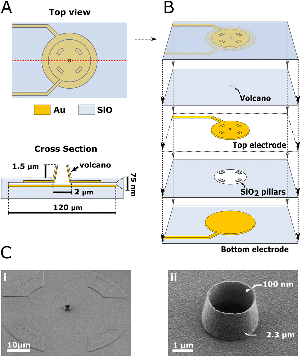 | ||
| Fig. 1 Device description. (A) Top view and cross-section of the device (not to scale). The volcano microelectrode (VME) is standing on top of a cavity whose floor and ceiling are covered by a set of individually addressable electrodes. The inter-electrodes distance is 75 nm. The ceiling electrode connects to the layer of gold covering the VME's inner wall. Hence the active electrodes surface includes both the cavity floor, ceiling and the VME's inner wall but not the VME's outer wall made from SiO2 as seen on the device cross section. (B) Device collapsed view showing the different layers (not to scale). From bottom to top: bottom electrode, SiO2 insulating layer with pillars, top electrode, SiO2 insulating layer with the VME and all layers combined. The SiO2 pillars ensure the two electrodes never come into contact. (C) Scanning electron micrographs of the finished device viewed with a tilt. (i) Shows the VME surrounded by the egress from the substrate caused from the underlying SiO2 pillars. (ii) Shows an enlarged view of the VME. | ||
Throughout most of this study, we used our devices in constant amperometry mode whereby the top and bottom electrodes are connected together and set to a positive potential with respect to the silver/silver chloride reference electrode, aimed at oxidizing the molecule of interest (Fig. 2A). Upon stimulation, cells undergo exocytosis and release catecholamines that diffuse to the electrode and are oxidized resulting in spikes in the amperometric trace (Fig. 2B). Spikes are then individually analyzed to retrieve their peak current, charge and full width at half maximum (FWHM) (Fig. 2C). When measuring exocytosis events, the contribution of the electrode's active surface within the cavity was found to be negligible from our simulation (see Materials and method section) probably because all catecholamine molecules were oxidized before reaching the cavity. In experiments measuring exocytosis events, the active electrode surface area can hence be approximated to the VME floor and inner wall (12.64 μm2 in total). However, the effective active electrode surface area seems to be lower as characterized by cyclic voltammetry and step-amperometry (ESI section 3 and ESI Fig. 4†) with a steady-state current equivalent to a recessed electrode of 3.14 μm2 surface area located 0.5 μm below the substrate level. Although the VME is not a recessed electrode strictly speaking because of its conductive inner wall, this result suggests that most electroactive molecules diffusing from the bulk to the electrode inside the VME during a potential controlled experiment are consumed before reaching the nanogap.
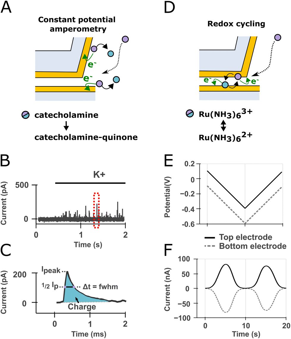 | ||
| Fig. 2 Device mode of operations sketched over a cross-section view of the device. (A) In constant amperometry mode the top and bottom electrodes are kept at the same constant potential. Catecholamine molecules released by exocytosis at the cell membrane (not depicted) diffuse to the electrodes and are oxidized to catecholamine-quinones. (B) The oxidation of catecholamine packets originating from single vesicle fusion events are registered as individual spikes on the current trace during cell stimulation with high potassium recording solution. (C) Enlarged view of the dashed red box in (B). Spikes are analyzed individually to extract the total charge (i.e., from the area under the curve through Faraday's law), peak current and full width at half maximum (FWHM). (D) In redox cycling mode, the potential of the top and bottom electrodes are set symmetrically apart from the formal potential of a redox mediator resulting in the mediator molecules undergoing oxidation and reduction up to several hundreds to thousands of times per seconds thereby amplifying the recorded current. (E) This can be achieved by scanning the potential of both electrodes with an offset. (F) The current traces will display anticorrelated peaks at the formal potential of the redox mediator. | ||
On the other hand, we also made use of the two electrodes being individually addressable to leverage a phenomenon known as electrochemical redox cycling to characterize the cell/VME interface. This detection scheme is not concerned with exocytosis but rather with the detection of electroactive molecules undergoing a reversible redox reaction and has been demonstrated down to the single-molecule detection levels.21 In the redox cycling mode, the potential of the two electrodes are set symmetrically apart from the formal potential of a redox mediator resulting in the mediator molecules undergoing oxidation and reduction up to several hundreds to thousands of times per seconds (Fig. 2D). When the two electrodes potential are scanned with an offset (Fig. 2E), the resulting current traces show anticorrelated peaks at the formal potential of the mediator molecule (Fig. 2F). We made use of this detection scheme below to assess whether molecules from the bulk can reach the confined detection volume created by the VME. In redox cycling mode, the electrode active surface area corresponds to the surface area of overlap between the floor and ceiling electrodes within the cavity (7850 μm2 corresponding to a disk 100 μm in diameter).
The wafers are diced into individual chips and a glass ring is glued on top of each chip to delimitate a culture chamber using polydimethylsiloxane (PDMS). The chromium sacrificial layer in between the gold electrodes is removed by potential-assisted wet etching as described in the ESI (section 2 and ESI Fig. 3†). We assessed the viability of cells cultured on VME after chromium removal (ESI Fig. 5†) and found a viability of 98.17 ± 0.19% (n = 10 field of views centered on different VMEs). We assessed the device yield by counting out the VMEs whose pair of electrodes were short-circuited (i.e., in physical contact) and found the yield was always over 85% with at least 24 out of 28 devices per chip operational.
2.2. Amperometric detection of exocytosis within volcano microelectrodes
We cultured PC12 cells on VMEs and conducted amperometric detection of catecholamine release upon stimulation with a recording solution altered to have a higher concentration of potassium (125 instead of 5.5 mM). In order to demonstrate the device's ability to capture biologically relevant fluctuations of exocytosis pattern, we stimulated and measured the resulting catecholamine release events at two different time points on the same culture: after one day and three days in culture (DIC) (Fig. 3; DIC1 and DIC3 respectively). | ||
| Fig. 3 Amperometric measurement of potassium-stimulated exocytosis from PC12 cells on volcano microelectrodes. (A) Application of an elevated potassium solution provokes exocytosis in PC12 cells although with different features one or three days (DIC1, DIC3) after the start of the culture. The traces are offset by 500 pA for clarity. The larger noise level in the upper trace results from an improper grounding of the syringe pump in that specific experiment. (B) Enlargement of the amperometric spikes within the red dotted box in (A). Spikes at DIC3 (purple) are often seen to be larger although of roughly same duration compared to DIC1 (black). (C–E) Comparison of spikes quantal size, peak current and full width at half maximum at DIC1 and DIC3 (one-sided Mann–Whitney rank-sum test, *p < 0.05, ns: not significant). n = 7 cells. (F) Comparison of the log-normalized quantal size distribution at DIC1 and DIC3. The bars of the histogram correspond to experimental data. Bin sizes were determined using the Freedman–Diaconis Estimator. Solid curves are best fit to a log–normal distribution. | ||
Typical recording traces are presented at both time points over the initial 4 seconds of stimulation (Fig. 3A) and show strong, continuous amperometric spikes. Sample amperometric spikes from both time points are displayed over a 10 ms window (Fig. 3B). To compare exocytosis at the two time points, we averaged the spike features per cell which is more reliable than comparing pooled data from the different cells recorded from.22 The two conditions are compared through their distribution of spike feature means (mean quantal size, mean peak current, mean FWHM, Fig. 3C, D and E respectively). The distribution of quantal size at the two time points followed a log–normal distribution (two-sample Wald–Wolfowitz runs test, significance level 0.05) and can be compared qualitatively through their log–normal distributions (Fig. 3F).23 The solid lines superposed over the histogram correspond to the best fit of a normal distribution.
2.3. Control of the chemical environment at the volcano microelectrode/cell interface
We made use of redox cycling to ascertain that molecules added to the extracellular bath can find their way to the portion of membrane within the VME. The ability to alter the chemical environment of the portion of the cell's membrane facing the electrode is important as it is needed to perform investigations of exocytosis encompassing pharmacological manipulations. To that end, we added hexaamineruthenium(III) to the extracellular bath and compared the redox cycling current obtained at VME free of or covered by a cell. We used hexaamineruthenium as a redox mediator since it is cell-impermeant and has been previously used for live PC12 cell studies in which it was found to minimally alter cell viability and dopamine release for short term experiments.24 After incubating the cells for 1 mn to allow the mediator to reach the VME (Fig. 4A), the two electrodes within a given VME were operated in redox cycling mode as described in Fig. 2D–F and the resulting current at both electrodes were recorded (Fig. 4B). Finally, we compared the magnitude of anodic and cathodic peak currents between free and cell-covered VMEs (Fig. 4C).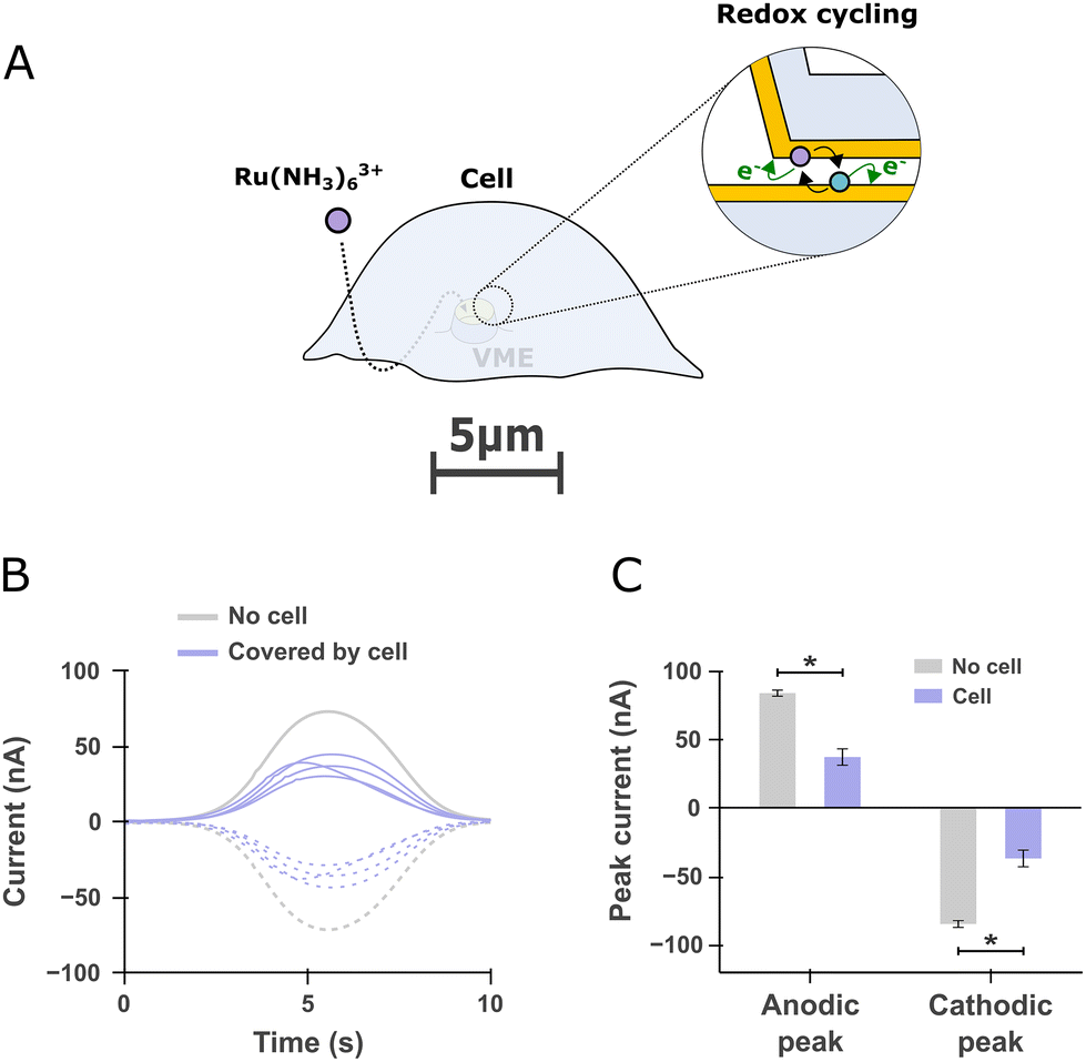 | ||
| Fig. 4 Redox cycling detection of a redox mediator diffusing inside free and cell-covered volcano microelectrodes (VME) (A) scheme depicting a cell covering a VME. A redox mediator (hexaamineruthenium) is added to the extracellular bath and subsequently detected by redox cycling within the VME. (B) Current traces recorded at a free VME compared to four other VMEs covered by PC12 cells. The solid line anodic and dashed cathodic traces corresponds to the currents registered at the top and bottom electrodes respectively as defined in Fig. 2E. (C) Comparison of the peak anodic and cathodic currents for free VMEs (n = 3) and cell-covered VMEs (n = 4). One-sided Mann–Whitney rank-sum test, *p < 0.05. | ||
2.4. Finite element modeling of exocytosis within volcano microelectrodes
In order to study the kinetics of the amperometric spikes measured, we performed finite element modeling (FEM) of catecholamine release from a vesicle, diffusion of the catecholamines and collection by amperometry within the VME. The simulation of fusion pore opening is a difficult problem given that the model has to be both time dependent and change its geometry over the course of vesicle fusion.25 Accordingly, we took another approach in which we treated vesicle fusion as a total and instantaneous release making our model rely on diffusion and oxidation rate at the electrode only.We constructed a 3D geometry representing the VME and closed its top surface with an impermeable boundary representing the cell membrane (Fig. 5A cross-section). The bottom (1), top (2) and wall (3) domains as labeled on the cross-section represent electrode surfaces that will oxidize catecholamine molecules (see Materials and methods for detailed implementations of the electrodes boundaries). The nanogap was trimmed at a radial distance of 1.325 μm from the center of the VME as it was found that the electrode surfaces within the nanogap region past the VME wall projection had no impact on the simulated spike. The vesicle was modeled as a spherical domain with a fixed concentration of 0.6 M of a molecule with diffusion coefficient of 4.1 × 10⁻⁸ cm2 s−1 inside the vesicle and 6 × 10⁻⁶ cm2 s−1 everywhere else, which are typical of catecholamines in the vesicle matrix26 and aqueous medium respectively.27 The quantal size was taken from our pooled experimental results at DIC3 (Fig. 3F) as 125 zeptomole or 75814 molecules. The position of the vesicle was varied along the radial axis but kept at a constant height, with its hemisphere across the no-flux boundary modeling the cell membrane.
 | ||
| Fig. 5 Finite element modeling of catecholamine diffusion within volcano microelectrode (VME) (A) schematic depicting a cross-section of the simulation geometry (cropped at r = 0). Boundaries in purple are modeled as electrode surfaces by imposing a Butler–Volmer boundary condition (see Materials and methods) while boundaries in blue are no flux conditions. The vesicle is shown as a black sphere of defined concentration and quantal size. (B) Simulated amperometric spikes when domains 1 and 2 are set as electrodes while domain 3 is either taken as an electrode (purple) or insulating (blue) surface. The black curve is the average of the experimental spikes obtained during potassium stimulation. A good fit to the experimental data is observed when domain 3 is taken as an active electrode surface. (C) Scanning electron micrographs of a VME electrodeposited with platinum under a tilted view. The electrodeposited platinum was highlighted in blue in image post-processing. The circular outgrowth of platinum along the VME inner wall supports the results in (B). (D) Detailed view of the simulation geometry highlighting the vesicle position with respect to the VME wall. (E) Simulated amperometric spikes obtained from vesicles at different distances from the VME wall. (F) Simulated spike features (peak current in purple, full width at half maximum in black) as a function of vesicle distance from the VME wall. The dotted line corresponds to simulated spike features that fall outside the variability of the pooled experimental data (displayed as shaded area corresponding to the experimental mean ± 2std. | ||
We first looked to ascertain whether or not the VME inner wall is conductive and participating in the electrode active surface area. Previous electrochemical impedance spectroscopy data28 and scanning electron microscope (SEM) images of VME cross-section29 have demonstrated that the inner wall of the VME is covered with metal redeposited by secondary ion sputtering during fabrication. However in the current study the thickness of metal etched that generated secondary ion sputtering is significantly thinner (50 nm gold + 10 nm titanium). It was therefore necessary to assess whether or not the inner part of the VME was part of the electrode active surface area to accurately simulate the diffusion processes.
We hence simulated amperometric spikes registered in the case of a conductive or insulating wall (Fig. 5A; domain 3 is set as an electrode or insulating boundary respectively) while keeping the vesicle at an arbitrary distance of 200 nm from the wall. The results are in favor of a conductive wall with the corresponding spike closely matching the experimental average spike (Fig. 5B). To further support this outcome we performed platinum electrodeposition over both electrodes of a VME simultaneously with the hypothesis that in the case of conductive walls the electrodeposited platinum would be localized both on the VME floor and walls. The SEM micrographs show a regular layer of platinum along the VME inner wall (Fig. 5C) providing further evidence of the VME inner wall being conductive.
Having established the electrode's active surface, we simulated the amperometric spikes resulting from vesicles at increasing distance from the wall (Fig. 5D). As the vesicle is positioned close to the wall, spikes become taller and narrower. In order to compare the experimental and simulated data, we shaded on the graph two areas that correspond to the range of the pooled experimental data observed (taken as the experimental mean ± 2 × standard deviation from Fig. 3D–E). Put in another way, any simulated data point within the shaded area of corresponding color is within two standard deviations of the experimental mean.
3. Results and discussion
3.1. Yield and advantages of the fabrication process
The fabrication of the device is exceptionally robust considering the pair of electrodes in each VMEs are separated by 75 nm only in the nanogap region. The yield obtained being consistently above 85% is a marked improvement to the 50% achieved before21 although our nanogap is almost twice as large. Nonetheless, our approach provides two considerable advantages. First, the transparent substrate used grants more flexibility for light microscopy along the cell culture lifetime. Although the VMEs are located at the center of the opaque metal electrode, transparent metal electrode materials like indium tin oxide could be used to obtain fully optically transparent chips.Secondly, our fabrication process is largely independent of residual stress in the different layers. This is achieved through the incorporation of SiO2 pillars in between the two electrodes that ensures that the electrodes remain separated after removal of the chromium layer (Fig. 1B). This fabrication approach and its advantages is discussed further in the ESI (section 5†).
3.2. PC12 cells exocytosis differs along time in culture
The measurement of potassium-stimulated exocytosis at different time points after passaging were markedly different to one another. A possible caveat in our experiment is the tentative impact of the cell positioning over the VME. We took care to record only from cells that were visibly covering a VME (ESI Fig. 7†). Furthermore, the variability we observe in our data (Fig. 3F coefficient of variation = 0.0158, n = 7 at DIC3) is similar to that reported before for PC12 cells (0.008, n = 18).30 Accordingly, it seems that optical inspection is enough to select appropriate recording sites.In our data, the most striking features of this development are the increased quantal size and peak current after three days (Fig. 3C and D; p < 0.05 one-sided Mann–Whitney rank-sum test). In both cases, the FWHM observed were still well below the milliseconds mark (424 ± 1.9 μs DIC1 and 451 ± 91 μs DIC3; mean ± SEM), which is considerably smaller than the few/tens of milliseconds commonly reported in the literature for PC12 cells.30 Nonetheless, the quantal size measured were in line with the admitted range of 100000 molecules30 (30669 ± 3341 catecholamine molecules per spike at DIC1 and 65580 ± 8568 at DIC3; mean ± SEM) The conservation of a typical quantal size despite much shorter events is explained by the large peak currents observed (21.3 ± 1.1 pA DIC1 and 57.0 ± 15.8 pA DIC3; mean ± SEM) as compared to typical values around 10 pA obtained with a conventional CFE.
A plausible explanation of the reduced quantal size and peak current at DIC1, shortly after cell plating, is the lack of interactions with the extracellular environment. Loss of cell–cell and cell–substrate interactions have been linked to impairment of exocytosis for example in mice pancreatic β-cells and neocortex/brainstem neurons through impairment of NCAM (Neural Cell Adhesion Molecules) and α-neurexin respectively.4,31 In a wider context, integrin interactions with the extracellular matrix are pivotal in localizing exocytosis for cell migration and recruitment of specific synaptobrevins during neuritogenesis.32,33 While there is no similar report for PC12 cells specifically to our knowledge, it seems plausible that the decreased quantal size arises from the transient disruption of intra/extracellular communications shortly after passaging.
The large peak current and small duration of the spikes we measured are not an effect of using microelectrodes per se as measurements on MEAs by others also reported FWHM clearly above the milliseconds mark at inlaid microelectrodes16 and recessed disk microelectrodes.18,20,34 This however raises an interesting possible improvement of the micro-electrode array described in this study. Including standard inlaid micro-electrodes among the array of VMEs would provide a readily available control that can be used as reference against which the exocytosis features measured at the VME electrode could be compared.
The data in that experiment were obtained from 7 cells for a total of 5722 spikes analyzed. The use of the VME array made the experimental workflow already significantly faster compared to an approach using a carbon fiber electrode since there was no need to engage the electrode on the cells. However, the use of an off-chip single-channel amplifier (Axopatch 200B) still severely limits the experimental throughput. This issue should be addressed in a future study integrating the VME presented on top of a recording circuitry (e.g., CMOS) to take the last step toward high-throughput experiments.
3.3. Cell membrane is accessible for pharmacological manipulation within the volcano microelectrode
A concern that may arise in our experiment is whether or not the elevated potassium solution used to stimulate cells could reach the portion of membrane covering the VME. As was shown by transmission electron microscopy (TEM)35 and voltage sensitive dye imaging,36 the cleft between cells and their substrate range in the tens of nanometers, which result in a tortuous diffusion pathway from the bulk of the culture chamber to the inside of the VME. Thanks to our novel sensor design encompassing two electrodes operable in redox cycling mode, we could ascertain that the chemical composition of the VME/cell interface quickly follows that of the extracellular bath. From the ratio of redox cycling current from free to cell-covered VME, we can estimate that the concentration of the redox mediator is halved at the VME/cell interface compared to the extracellular bath, at least within the first minutes after additions to the extracellular bath (Fig. 4C). This is acceptable considering that potassium concentration down to 30 mM can induce exocytosis in PC12 cells.37It could be argued that the redox mediator finding its way in one direction supposes that catecholamine molecules could escape the confined detection volume by diffusing the same way but in the opposite direction during exocytosis. However, since the electrode oxidizes molecules almost instantly, the concentration of catecholamine within the VME remains negligible at all times; i.e., catecholamines do not accumulate at the electrode. Consequently, the flux of catecholamine escaping the VME through a nanometric slits necessarily has to be small in comparison to the unobstructed flux of molecules to the much larger electrodes of micrometric size.
3.4. Diffusion within the volcano microelectrode has sub-milliseconds timescale
An important question that arises from our data is the cause of the faster release kinetics observed. SSVs present at the neuronal synapse undergo flickering exocytosis with a time scale of hundreds of microseconds.5 However, PC12 are reported to essentially secrete catecholamine stored in LDCVs-like vesicles in response to potassium stimulation with a second small vesicle pool containing non-electroactive acetylcholine.38 We also analyzed the electroactive molecules found in the PC12 cells used in this study with 3-hydroxyphenyl boronic acid fluorometry and confirmed their catecholaminergic nature (ESI Fig. 6†). Hence, we cannot attribute the release events we observed to another vesicle pool.It could be hypothesized that the VME conical geometry forms a funnel from the release site to the electrode and that the confined volume of the VME results in less dilution and hence a steeper concentration gradient from the vesicle to the electrode. This hypothesis is however in disagreement with experimental results using recessed cavity carbon electrodes which register amperometric spikes of similar duration to those from a conventional CFE.15 A significant difference of the VME however lies in the fact that the inner wall of the recess is itself conductive as evidenced by our simulated data (Fig. 5B) and in situ electrodeposition of platinum (Fig. 5C).
Under the assumption of a conductive inner wall of the VME, exocytotic release at varying distances from the wall results in a distribution of spikes of equal charge but varying peak currents and FWHMs (Fig. 5E) that captures well the variability of the experimental data (Fig. 5F). At large vesicle distance from the wall we see the experimental and simulated data converge to similar values of FWHM (436 μs) and peak current (35 pA). On the other hand, simulated data at vesicle distance from the wall below 500 nm predict faster, taller spikes, which are not found within the experimental data. Instead experimental data reach a maximum/minimum in peak current and FWHM respectively that could be attributed to diffusion time becoming small compared to the opening of the vesicle fusion pore. In absence of an appropriate modeling of the fusion pore opening, this hypothesis remains to be confirmed.
Additionally, the present simulation does not allow us to conclude whether exocytosis takes place preferentially from membrane portions close to the VME wall or rather at the center of the VME. In this scope, TEM imaging of the cell membrane conformation within the VME would prove very valuable and perhaps reveal preferential vesicle localization close to or far away from the VME wall rim. Still, the conclusion we draw from simulating the impact of vesicle position is twofold. First, simulated diffusion times within the VME are within the experimental bounds and hence do not challenge the plausibility of our data. Second, on top of diffusion being fast (sub-millisecond timescale), the kinetic of vesicle fusion needs to be faster as well since it usually takes place over a few milliseconds.7
3.5. Hypothetical impact of volcano microelectrodes on membrane tension and cytoskeleton arrangement
The factors influencing vesicle fusion kinetics can be broadly separated into two categories: physicochemical and biomolecular factors. An example of the former and latter could respectively be (i) the impact of extracellular ionic composition39 and (ii) the impact of the cell and vesicle membrane's lipidic composition.40,41A plausible hypothesis to reconcile our observations with admitted vesicle fusion kinetics could be the impact of membrane curvature and tension arising from the sharp VME wall (150 nm thick). It was observed by several investigators that hypotonic conditions result in faster, more frequent exocytosis while the converse is true for hypertonic conditions.7,42 The resulting spikes in hypotonic conditions are shorter in duration of both the rising and decaying phase of the spikes, which are associated with rate of opening of the fusion pore and diffusion of catecholamine out of the vesicle matrix7 yet with conserved quantal size.43 Our experiments did not involve osmolarity manipulation yet a possible role of the plasma membrane tension in the fast exocytosis kinetics we observe is plausible since it was demonstrated that membrane deformation brought by nanotopography induces membrane tension.44 Although the cell membrane was shown to be able to accommodate microscale vertical features from its substrate,45 the more subtle impact of local curvature on the nanoscale is believed to develop significant stress in the cell membrane even leading to membrane disruption.46 The fact that nanotopography can induce enough hoop stress to cause membrane failure whereas there was no such report in the classical hypotonic experiment suggests that the magnitude of the membrane stress induced by nanotopography is greater. Since hypotonic conditions did shorten exocytosis timescale by roughly 30%,7 it seems reasonable that even stronger membrane stress caused by nanotopography might lead to a more drastic shortening of the exocytosis duration; down to fractions of milliseconds as found in our experiments.
An ensuing argument is that the membrane deformation might alter the molecular composition of the membrane and/or cytoskeleton in the vicinity of the VME wall rim. This is supported by a vast literature on protein localization to curved membrane domains like α-synuclein,47 complexin48 and BAR domains-containing proteins in general.49 In particular, nanotopography was demonstrated to induce the recruitment of FBP17, a membrane curvature sensing protein, leading to filamentous actin assembly (F-actin) through action of the neuronal Wiskott–Aldrich syndrome protein (N-WASP) in U2OS cells.50 Interestingly, independent findings revealed the role of F-actin polymerization, also mediated by N-WASP, in providing enough membrane surface tension to enable the merging of vesicles with the chromaffin cell membrane.51,52 Taken together the impact of nanotopography on membrane tension and cytoskeleton rearrangement substantiates the hypothesis that the VME wall sharpness alters exocytosis kinetics. This hypothesis gives away some very interesting investigation prospects since to our knowledge there only exists one report of nanotopography impact on lateral vesicle movement53 but none about exocytosis itself.
3.6. Comparison to patch amperometry
A possible caveat of our hypotheses is the consideration that patch amperometry54 would effectively result in a similar if not stronger membrane tension, which by deduction should result in shorter events duration. Yet, amperometric spikes registered using this technique have features close to those reported by conventional CFE. It should be noted however that in patch amperometry the carbon electrode is separated from the tip of the pipette by typically 6–7 μm.54 This separation results in convolution of the release kinetics with the subsequent diffusion to the electrode, which should yield spikes duration in the tens of millisecond range. An interesting detail is the report that establishment of the gigaohm seal during patch amperometry results in spontaneous exocytotic releases.54,55 This observation and other reports on swelling-activated ion channels could propose a greater susceptibility of exocytosis at deformed region of the cell membrane yet remains to be investigated.4. Conclusions
In this study we have described a new electrochemical sensor capable of multi-site, sensitive single cell measurement. This new sensor encompasses a robust fabrication process that allows to outfit each VME with two individually addressable electrodes instead of one. The two electrodes are arranged in a nanogap configuration, a novelty that we put to use to shed light on the cell/microstructure interface thanks to a redox cycling detection scheme. The sensor applied to single cell amperometry of exocytosis achieves sensitive detection that can resolve maturation in cellular mechanisms in culture.A limitation of the current study is the small number of cells the data were collected from. Although our VME arrays like other MEAs allow a high number of simultaneous sensing sites, our experiment yield was limited by the random pairing of VME and cells and the use of a single channel amplifier. Others have addressed the former by defining zone of preferential attachment for cells around the microelectrodes,18,20 which could be implemented in the future together with other approaches like cell specific dielectrophoretic patterning.56 Finally, CMOS integration as implemented by others20 are a common strategy to parallelize recordings thereby increasing throughput.
The short time scale of the spikes observed led us to build a set of hypotheses relying on the increased membrane tension and cytoskeleton reshaping plausibly brought by the VME wall having sub-micron thickness. There exists a vast literature about the impact of nanostructures on cell mechanisms like differentiation,57 migration58 and signaling59 yet their impact on exocytosis remains to be explored. Accordingly, VMEs stand as an interesting platform to explore this question. A straightforward way to test our hypothesis could be to use pharmacological or genetic manipulations to perturb the hypothetical actin polymerization over the VME rim using latrunculin A or Actb knockout respectively. On the other hand, varying the VME geometry (e.g., wall thickness, height, diameter) could also be used to challenge or refine this hypothesis. Our current data offer a novel view of exocytotic behavior under membrane deformation and could foster further investigations of the impact of nanotopography on synaptic mechanisms and cellular mechanosensing.
5. Materials and methods
5.1. Fabrication of the devices
The fabrication process flow is described and depicted step by step in the ESI (section 1 and ESI Fig. 1†). Briefly, four inches fused silica substrates were evaporated with Ti/Au/Cr of 7/50/70 nm which was patterned by i-line photolithography and ion beam etching to define the region of overlap of the two gold electrodes and silicon dioxide pillars. The bottom gold electrode itself was defined in subsequent photolithography/etching similarly. A 200 nm thick insulating layer of silicon dioxide was deposited by plasma enhanced physical vapor deposition (PECVD) and subsequently patterned by photolithography/etching to open an access to the chromium and define the silicon dioxide pillars. Cr/Au/Ti of 5/60/7 nm was sputtered and patterned to form the top electrode. A second 300 nm thick insulating layer of silicon dioxide was deposited by PECVD and patterned by photolithography/etching to define the VME itself and access contact of the electrodes. The wafers were diced on a DAD321 (Disco, Germany) with a resinoid blade of 70 μm width under 25000 rpm rotation moving at 1 mm s−1 from the top side of the wafer.
A glass O-ring was glued on top of the individual chips using PDMS and cured overnight at 60 °C in a convection oven. The removal of the chromium sacrificial layer was carried out at this point by potential assisted wet etching followed by device yield assessment as detailed in the ESI (section 2 and ESI Fig. 3†). The device electrochemical response was characterized in cyclic voltammetry and step chronoamperometry (section 3 and ESI Fig. 4†).
5.2. Thin film stress measurements
Residual stress measurements of PECVD deposited thin films of SiO2 and Si3N4 were carried out on different four inches 525 μm thick substrates: 〈100〉 p-type silicon, 〈100〉 p-type silicon with 500 nm wet oxide and fused silica. The substrate radius of curvature was measured before and after deposition using a FLX 2320-S (Toho Technology, USA) and the thin film stress was found using the Stoney equation.5.3. Cell culture
The device culture chamber formed by the glass O-ring glued on top was incubated with poly-D-lysine (A3890401, ThermoFisher) for 1 h at room temperature. After rinsing 5 times with DIW, the culture chamber was filled with culture medium and kept at 37 °C until cell plating.Pheochromocytoma 12 rat cells were obtained from the European Collection of Cell Cultures. Cells from passage 10 to 15 were used. The catecholamine content of PC12 cells was determined by fluorometric measurement following reaction of catecholamines with 3-hydroxyphenyl boronic acid.60 The detailed lysis and assay protocol are detailed in the ESI (section 4 and ESI Fig. 6†).
During cell culture the cells were kept in RPMi-1640 supplemented with Glutamax (61870036, ThermoFisher), 10% heat-inactivated donor equine serum (26050070, ThermoFisher), 5% fetal bovine serum (F9665, Merck) and 0.4% penicillin/streptomycin (P4333, Merck) solution within a 37 °C incubator under 7% CO2 and 100% humidity atmosphere. Before plating on the devices, a 80% confluent culture was collected by trypsinization (1084440001, Merck) for 5 mn at 37 °C followed by mechanical dislodgement by repetitive pipette dispensing over the cell. Cells were centrifuged 2 mn at 0.3 RCF and resuspended in culture medium after the supernatant was discarded. We plated 150000 cells per chip (0.95 cm2) and conducted experiments on the third day after passaging.
In another experiment we cultured Human Embryonic Kidney cells on our chip in a similar way except for the medium (DMEM supplemented with Glutamax; 10566016 ThermoFisher) and no equine donor serum but 10% fetal bovine serum. On the third day after passaging we assessed cell viability by calcein-AM/ethidium homodimer-1 assay (L3224; ThermoFisher) according to the manufacturer protocol. We analyzed 10 fields of view of 610 × 460 μm centered on a single VME. Using the CellProfiler (CellProfiler™, Broad Institute) methods “identifyPrimaryObjects” we identified, segmented and counted individual cells to obtain the ratio of live cells to total cells in a given field of view (ESI Fig. 5†).
5.4. Amperometric experiments
On the third day after passaging, the medium culture was exchanged for a recording buffer (in mM; 125 NaCl, 5.5 KCl, 1.8 CaCl2, 0.8 MgCl2, 20 HEPES, 24 glucose, and 36 sucrose at pH 7.3, osmolarity adjusted to 315 mOsm with sucrose) and allowed to equilibrate for 10 mn at room temperature during which time VME covered by a cell were identified using an epifluorescence microscope under bright field illumination. The device was placed inside a custom printed circuit board interface itself within a faraday cage to limit electromagnetic interference and light exposure that would react with the HEPES in our buffer. The selected VMEs were sequentially connected to the input of an Axopatch 200 B amplifier (Molecular Devices, USA) by connecting both electrodes of the VME tot the amplifier input while the ground of the amplifier was connected to a silver/silver chloride pellet (E-205; Multi Channels System, Germany) immersed in the culture chamber bath. The VME's electrodes were biased to +600 mV with respect to ground.The cells were stimulated using an elevated potassium solution (same as recording buffer but with KCl elevated to 125 mM and NaCl reduced to 5.5 mM dispensed by a Nemesys Base120 syringe pump (Cetoni, Germany). The tubing outlet connecting to the elevated potassium solution syringe was positioned 3 mm above the MEA and dispensed at a rate of 20 μL s−1 while another tubing positioned 6 mm above the MEA withdrew an equal volume at an equal flow rate. After stimulation the culture chamber was exchanged in a similar way using a third syringe filled with standard recording solution and the next recording (typically from another cell) was started after a 5 mn break.
5.5. Data acquisition and analysis
Data were filtered with the built-in Axopatch 200B four-pole low-pass Bessel filter set to a cut-off frequency of 10 kHz and digitized at 100 kHz using a Powerlab 4/25 acquisition card (AD Instruments, Australia). The signal was also digitized on another channel after high-pass filtering using the acquisition card single-pole analog high-pass filter set to a cut-off frequency of 10 Hz. In the rest of data processing the 10 kHz low-pass, 10 Hz high-pass signal was used. Spikes above 3.75 to 5 times the standard deviation of the noise, depending on the specific recording noise level, were selected. The spike start and end used to compute total quantal size were found as the first occurrence of a sample below one time the noise standard deviation on a 3 sample rolling-averaged version of the signal. The spike features distributions are plotted on a log-scale and fitted by a log–normal distribution of parameter μ = mean and σ = standard deviation. All results in the text are reported as the mean ± standard error of the mean.5.6. Redox cycling detection on cell covered volcano microelectrodes
At the end of an amperometric experiment, the recording solution was exchanged with a similar solution that was supplemented with 100 μM hexaammineruthenium(III) chloride (262005, Merck). The cells were incubated in that solution for 1 mn before recording. The top electrode of a given selected VME was connected to the first working electrode of the bipotentiostat (same as above) and the bottom electrode was connected to the second working electrode. The counter electrode was a platinum wire and the reference electrode a chlorinated silver wire. The potential of the two working electrodes were scanned simultaneously from −100 mV to −600 mV with an offset of +200 mV. This results in a transient centered at the formal potential of the redox probe as was used for multiplexed electrochemical detection referred to as differential cyclic voltammetry.61 In our experiment, comparing the current trace obtained at VMEs covered or not covered by a cell allows us to assess the ability of molecules to diffuse inside covered VMEs (ESI Fig. 8†).5.7. Numerical simulations
Finite element modeling was performed with Comsol Multiphysics® according to a previous report.62 The VME geometry was defined as described in the Experimental section and depicted in Fig. 5A. The nanogap was trimmed at a radial distance of 1.325 μm from the center of the VME as it was found that the electrode surfaces within the nanogap region past the VME wall projection had no impact on the simulated spike. To model the oxidation of catecholamine at the electrode surfaces, a Butler–Volmer flux defined by eqn 1 was imposed on all segments modeling electrodes while all other boundaries were constrained to no flux (Fig. 5A purple and blue respectively).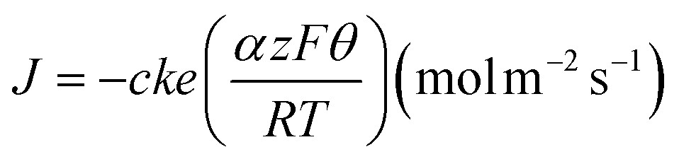 | (1) |
In eqn (1), J is the flux of molecules, c the molecule concentration at the electrode surface in mol m−3, k the heterogeneous reaction rate at the formal potential was set to 0.025 cm s−1,63α the symmetry factor was set to 0.5, z the number of electrons involved in the reaction, F is the faraday constant, Θ the overpotential was set to 0.4 volt (i.e., 0.6 volt for the reduction of dopamine on a gold electrode), R is the gas constant, T the temperature was set to 298.15 Kelvin. Current at the electrodes was obtained by integrating eqn 1 over all surfaces defined as electrodes. Plotting the resulting current against time yields the simulated amperometric spike. The release of catecholamine from the vesicle was simplified to an instantaneous release and the quantal size was taken from the experimental results as 125 zeptomole localized within a vesicle of diameter determined by a fixed concentration of 0.6 M. The mesh elements were taken as quadrilaterals. Meshing of the geometry was carefully optimized with refinements along all electrodes surfaces, corners and edges. We performed a mesh refinement sweep until no change of the spike features were observed leading to meshes with about 500000 elements.
Author contributions
N. M., A. B. and P. R. conceived the project and experiments. N. M. conducted the microfabrication and experiments. N. M. wrote the manuscript and analyzed the data. All authors participated in the discussion of the results and revision of the manuscript.Conflicts of interest
The authors report no conflict of interest.Acknowledgements
This work was funded by the Swiss National Science Foundation (grant number 200021_175943 to P. R.). The authors would like to thank the staff of the Center of micro-nanofabrication at EPFL for their outstanding help and flawless infrastructures. We acknowledge Olexiy Kochubey for his invaluable critical opinion on the first data obtained, Benoît Desbiolles for his advises early in the project and Joan Teixidor for his insight in the catecholamine fluorometric assay.References
- H. Fathali, J. Dunevall, S. Majdi and A.-S. Cans, J. Visualized Exp., 2018, e56537 Search PubMed.
- R. M. Wightman, J. A. Jankowski, R. T. Kennedy, K. T. Kawagoe, T. J. Schroeder, D. J. Leszczyszyn, J. A. Near, E. J. Diliberto and O. H. Viveros, Proc. Natl. Acad. Sci. U. S. A., 1991, 88, 10754–10758 CrossRef CAS PubMed.
- D. Sulzer and E. N. Pothos, Rev. Neurosci., 2000, 11, 159–212 CAS.
- M. Missler, W. Zhang, A. Rohlmann, G. Kattenstroth, R. E. Hammer, K. Gottmann and T. C. Südhof, Nature, 2003, 423, 939–948 CrossRef CAS PubMed.
- R. G. W. Staal, E. V. Mosharov and D. Sulzer, Nat. Neurosci., 2004, 7, 341–346 CrossRef CAS PubMed.
- R. H. Chow, L. von Rüden and E. Neher, Nature, 1992, 356, 60–63 CrossRef CAS PubMed.
- T. J. Schroeder, R. Borges, J. M. Finnegan, K. Pihel, C. Amatore and R. M. Wightman, Biophys. J., 1996, 70, 1061–1068 CrossRef CAS PubMed.
- T. Xu, T. Binz, H. Niemann and E. Neher, Nat. Neurosci., 1998, 1, 192–200 CrossRef CAS PubMed.
- G. Nosov, M. Kahms and J. Klingauf, Front. Synaptic Neurosci., 2020, 12, 32 CrossRef CAS PubMed.
- T. J. Schroeder, J. A. Jankowski, J. Senyshyn, R. W. Holz and R. M. Wightman, J. Biol. Chem., 1994, 269, 17215–17220 CrossRef CAS PubMed.
- A. V. Leopold, D. M. Shcherbakova and V. V. Verkhusha, Front. Cell. Neurosci., 2019, 13, 474 CrossRef CAS PubMed.
- J. Schmoranzer, M. Goulian, D. Axelrod and S. M. Simon, J. Cell Biol., 2000, 149, 23–32 CrossRef CAS PubMed.
- N. G. Gubernator, H. Zhang, R. G. W. Staal, E. V. Mosharov, D. B. Pereira, M. Yue, V. Balsanek, P. A. Vadola, B. Mukherjee, R. H. Edwards, D. Sulzer and D. Sames, Science, 2009, 324, 1441–1444 CrossRef CAS PubMed.
- D. Bruns, Methods, 2004, 33, 312–321 CrossRef CAS PubMed.
- G. S. McCarty, L. E. Dunaway, J. D. Denison and L. A. Sombers, Anal. Chem., 2022, 94, 9548–9556 CrossRef CAS PubMed.
- X. Sun and K. D. Gillis, Anal. Chem., 2006, 78, 2521–2525 CrossRef CAS PubMed.
- C. Spégel, A. Heiskanen, J. Acklid, A. Wolff, R. Taboryski, J. Emnéus and T. Ruzgas, Electroanalysis, 2007, 19, 263–271 CrossRef.
- X. Liu, S. Barizuddin, W. Shin, C. J. Mathai, S. Gangopadhyay and K. D. Gillis, Anal. Chem., 2011, 83, 2445–2451 CrossRef CAS PubMed.
- J. Wang and A. G. Ewing, Analyst, 2014, 139, 3290–3295 RSC.
- M. Huang, J. B. Delacruz, J. C. Ruelas, S. S. Rathore and M. Lindau, Pfluegers Arch., 2018, 470, 113–123 CrossRef CAS.
- S. Kang, A. F. Nieuwenhuis, K. Mathwig, D. Mampallil and S. G. Lemay, ACS Nano, 2013, 7, 10931–10937 CrossRef CAS PubMed.
- T. L. Colliver, E. J. Hess, E. N. Pothos, D. Sulzer and A. G. Ewing, J. Neurochem., 2000, 74, 1086–1097 CrossRef CAS PubMed.
- E. V. Mosharov and D. Sulzer, Nat. Methods, 2005, 2, 651–658 CrossRef CAS PubMed.
- J. M. Liebetrau, H. M. Miller, J. E. Baur, S. A. Takacs, V. Anupunpisit, P. A. Garris and D. O. Wipf, Anal. Chem., 2003, 75, 563–571 CrossRef CAS PubMed.
- C. Amatore, A. I. Oleinick and I. Svir, ChemPhysChem, 2010, 11, 159–174 CrossRef CAS PubMed.
- C. Amatore, Y. Bouret, E. R. Travis and R. M. Wightman, Biochimie, 2000, 82, 481–496 CrossRef CAS PubMed.
- G. Gerhardt and R. N. Adams, Anal. Chem., 1982, 54, 2618–2620 CrossRef CAS.
- B. X. E. Desbiolles, E. de Coulon, A. Bertsch, S. Rohr and P. Renaud, Nano Lett., 2019, 19, 6173–6181 CrossRef CAS PubMed.
- B. X. E. Desbiolles, A. Bertsch and P. Renaud, Microsyst. Nanoeng., 2019, 5, 1–8 CrossRef PubMed.
- R. H. S. Westerink, A. de Groot and H. P. M. Vijverberg, Biochem. Biophys. Res. Commun., 2000, 270, 625–630 CrossRef CAS PubMed.
- C. S. Olofsson, J. Håkansson, A. Salehi, M. Bengtsson, J. Galvanovskis, C. Partridge, M. SörhedeWinzell, X. Xian, L. Eliasson, I. Lundquist, H. Semb and P. Rorsman, Endocrinology, 2009, 150, 3067–3075 CrossRef CAS PubMed.
- G. Wang and T. Galli, Traffic, 2018, 19, 741–749 CrossRef CAS.
- S. L. Gupton and F. B. Gertler, Dev. Cell, 2010, 18, 725–736 CrossRef CAS.
- P. Chen, B. Xu, N. Tokranova, X. Feng, J. Castracane and K. D. Gillis, Anal. Chem., 2003, 75, 518–524 CrossRef CAS PubMed.
- F. Santoro, W. Zhao, L.-M. Joubert, L. Duan, J. Schnitker, Y. van de Burgt, H.-Y. Lou, B. Liu, A. Salleo, L. Cui, Y. Cui and B. Cui, ACS Nano, 2017, 11, 8320–8328 CrossRef CAS PubMed.
- D. Braun and P. Fromherz, Biophys. J., 2004, 87, 1351–1359 CrossRef CAS PubMed.
- T. A. Mir, M. H. Akhtar, N. G. Gurudatt, J.-I. Kim, C. S. Choi and Y.-B. Shim, Biosens. Bioelectron., 2015, 68, 421–428 CrossRef CAS PubMed.
- R. H. S. Westerink and A. G. Ewing, Acta Physiol., 2008, 192, 273–285 CrossRef CAS PubMed.
- J. A. Jankowski, J. M. Finnegan and R. M. Wightman, J. Neurochem., 1994, 63, 1739–1747 CrossRef CAS PubMed.
- M. Aref, E. Ranjbari, A. Romiani and A. G. Ewing, Chem. Sci., 2020, 11, 11869–11876 RSC.
- C. Gu, M. H. Philipsen and A. G. Ewing, Int. J. Mol. Sci., 2020, 21, 9519 CrossRef CAS PubMed.
- R. Borges, E. R. Travis, S. E. Hochstetler and R. M. Wightman, J. Biol. Chem., 1997, 272, 8325–8331 CrossRef CAS PubMed.
- C. Amatore, S. Arbault, I. Bonifas, Y. Bouret, M. Erard and M. Guille, ChemPhysChem, 2003, 4, 147–154 CrossRef CAS PubMed.
- X. Xie, A. M. Xu, M. R. Angle, N. Tayebi, P. Verma and N. A. Melosh, Nano Lett., 2013, 13, 6002–6008 CrossRef CAS PubMed.
- M. Dipalo, A. F. McGuire, H.-Y. Lou, V. Caprettini, G. Melle, G. Bruno, C. Lubrano, L. Matino, X. Li, F. De Angelis, B. Cui and F. Santoro, Nano Lett., 2018, 18, 6100–6105 CrossRef CAS PubMed.
- R. Capozza, V. Caprettini, C. A. Gonano, A. Bosca, F. Moia, F. Santoro and F. De Angelis, ACS Appl. Mater. Interfaces, 2018, 10, 29107–29114 CrossRef CAS PubMed.
- M. B. Jensen, V. K. Bhatia, C. C. Jao, J. E. Rasmussen, S. L. Pedersen, K. J. Jensen, R. Langen and D. Stamou, J. Biol. Chem., 2011, 286, 42603–42614 CrossRef CAS PubMed.
- J. Gong, Y. Lai, X. Li, M. Wang, J. Leitz, Y. Hu, Y. Zhang, U. B. Choi, D. Cipriano, R. A. Pfuetzner, T. C. Südhof, X. Yang, A. T. Brunger and J. Diao, Proc. Natl. Acad. Sci. U. S. A., 2016, 113, E7590–E7599 CrossRef CAS PubMed.
- H. T. McMahon and E. Boucrot, J. Cell Sci., 2015, 128, 1065–1070 CrossRef CAS PubMed.
- H.-Y. Lou, W. Zhao, X. Li, L. Duan, A. Powers, M. Akamatsu, F. Santoro, A. F. McGuire, Y. Cui, D. G. Drubin and B. Cui, Proc. Natl. Acad. Sci. U. S. A., 2019, 116, 23143–23151 CrossRef CAS PubMed.
- W. Shin, L. Ge, G. Arpino, S. A. Villarreal, E. Hamid, H. Liu, W.-D. Zhao, P. J. Wen, H.-C. Chiang and L.-G. Wu, Cell, 2018, 173, 934–945 CrossRef CAS PubMed , e12.
- P. J. Wen, S. Grenklo, G. Arpino, X. Tan, H.-S. Liao, J. Heureaux, S.-Y. Peng, H.-C. Chiang, E. Hamid, W.-D. Zhao, W. Shin, T. Näreoja, E. Evergren, Y. Jin, R. Karlsson, S. N. Ebert, A. Jin, A. P. Liu, O. Shupliakov and L.-G. Wu, Nat. Commun., 2016, 7, 12604 CrossRef CAS PubMed.
- J. Zhang, D. Fu, M. B. Chan-Park, L.-J. Li and P. Chen, Adv. Mater., 2009, 21, 790–793 CrossRef CAS.
- A. Albillos, G. Dernick, H. Horstmann, W. Almers, G. A. de Toledo and M. Lindau, Nature, 1997, 389, 509–512 CrossRef CAS PubMed.
- G. Dernick, G. Alvarez de Toledo and M. Lindau, Nat. Cell Biol., 2003, 5, 358–362 CrossRef CAS PubMed.
- T. Zhou, S. F. Perry, Y. Ming, S. Petryna, V. Fluck and S. Tatic-Lucic, Biomed. Microdevices, 2015, 17, 62 CrossRef PubMed.
- M. J. Dalby, N. Gadegaard and R. O. C. Oreffo, Nat. Mater., 2014, 13, 558–569 CrossRef CAS PubMed.
- Y. Yang, K. Wang, X. Gu and K. W. Leong, Engineering, 2017, 3, 36–54 CrossRef CAS PubMed.
- A. Zhang, J.-H. Lee and C. M. Lieber, Nano Today, 2021, 38, 101135 CrossRef CAS PubMed.
- X. Liu, M. Tian, W. Gao and J. Zhao, J. Anal. Methods Chem., 2019, 2019, e6540397 Search PubMed.
- M. J. J. van Megen, M. Odijk, J. Wiedemair, W. Olthuis and A. van den Berg, J. Electroanal. Chem., 2012, 681, 6–10 CrossRef CAS.
- A. Lavacchi, U. Bardi, C. Borri, S. Caporali, A. Fossati and I. Perissi, J. Appl. Electrochem., 2009, 39, 2159 CrossRef CAS.
- R. P. Bacil, L. Chen, S. H. P. Serrano and R. G. Compton, Phys. Chem. Chem. Phys., 2020, 22, 607–614 RSC.
Footnote |
| † Electronic supplementary information (ESI) available. See DOI: https://doi.org/10.1039/d2an01779b |
| This journal is © The Royal Society of Chemistry 2023 |