
 Open Access Article
 This Open Access Article is licensed under a
 Creative Commons Attribution 3.0 Unported Licence
Understanding the role of metal supported on TiO2 in photoreforming of oxygenates
Imran
Majeed
ac,
Hassan
Ali
c,
Afifa
Idrees
b,
Ayesha
Arif
b,
Warda
Ashraf
d,
Shahid
Rasul
e,
Mohd Adnan
Khan
f,
Muhammad Arif
Nadeem
 c and
Muhammad Amtiaz
Nadeem
*g
c and
Muhammad Amtiaz
Nadeem
*g
aApplied Chemistry Laboratories, PAEC, Islamabad, Pakistan
bDepartment of Chemistry, GC University, Lahore, Pakistan
cDepartment of Chemistry, Quid-i-Azam University, Islamabad, Pakistan
dDepartment of Chemistry, University of Management & Technology, Lahore, Pakistan
eFaculty of Engineering and Environment, Northumbria University, Newcastle Upon Tyne, UK
fDepartment of Chemical and Materials Engineering, University of Alberta, Edmonton, Alberta, Canada
gSABIC-Corporate Research and Development (CRD) at KAUST, Thuwal, Saudi Arabia. E-mail: NadeemMI@SABIC.com
First published on 3rd October 2022
Abstract
To achieve net-zero targets regarding GHG emissions by 2050, the identification of sustainable energy vectors is critical. In this context, photoreforming presents a potential candidate for recycling and transforming widely available biomass-derived wastes into clean hydrogen fuel, such as crude glycerol from biodiesel and a potential future H2 production opportunity from bioethanol. Many years of work has proved that TiO2 is an excellent material for photoreforming of organics due to its stability, availability, and environmentally friendly characteristics as compared to other semiconductors. However, photoreforming faces several obstacles, including the comparatively low hydrogen generation under Sun-equivalent light sources and the need of expensive noble metals. Efforts have been made in several directions, such as extending light absorption by TiO2 to the visible range, reducing the recombination rate of charge carriers, and preventing back reactions. To overcome these challenges, many methods have been proposed, such as controlling the phase and morphology of TiO2 nanoparticles, decoration with various metal co-catalysts, doping with metal and non-metal ions, plasmonic enhancement, and preparation of composite systems. Although each approach has its own merits, metal loading has proven to be the most effective among them all. This review provides a deep insight into the underlying role of metal towards the enhancement of TiO2 catalytic activity, focusing on the findings of recent published work. We discuss in detail the effect of various metals on TiO2 electronic structure, preparation methods, role in light absorption (surface Plasmon resonance) and chemical changes during various photoreforming steps. Following this we extend our discussion to dye sensitized systems and catalyst testing benchmarking. At the end of the review, we provide possible future research directions to enhance the photocatalytic activity of TiO2 based photocatalysts for photoreforming.
 Imran Majeed | Dr Imran Majeed is currently working in the Pakistan Atomic Energy Commission in Islamabad, Pakistan, as a Principal Scientist. In 2018, he received his PhD from the Department of Chemistry at Quaid-i-Azam University in Islamabad, Pakistan. His PhD research focused on employing visible light active TiO2 based photocatalysts to produce hydrogen from renewable sources. Imran has published over 20 papers related to hydrogen production using non-noble metal supported TiO2 and CdS photocatalysts. |
 Hassan Ali | Hassan Ali is currently a PhD scholar in the Department of Chemistry, Tsinghua University, Peoples Republic of China. In 2015, He received his master degree (M. Phil) from the Department of Chemistry at Quaid-I-Azam University, Islamabad, Pakistan. He obtained his Bachelor degree from the Department of Chemistry, The Islamia University of Bahawalpur, Pakistan in 2009. His Master degree research focused on the developing graphene based electroactive nanomaterials for fuel cell applications. Hassan has more than 10 research papers related to hydrogen production from electrocatalysis/photocatalysis. |
 Shahid Rasul | Dr Shahid Rasul is currently working as lecturer at Northumbria University, New Castle, UK. His major research focus is to develop efficient energy conversion and storage devices by photo-electrochemical processes for sustainable and renewable fuels. He conducts fundamental research in science and engineering of energy materials. He has expertise in designing the surface and bulk properties of materials in such a way that improves the energy efficiency of both energy conversion and storage devices. |
 Mohd Adnan Khan | Dr Mohd Adnan Khan is an Assistant Professor in the Chemical and Materials Engineering Department at the University of Alberta. Adnan has nearly a decade of experience working along the value chain of hydrogen and clean technology development. His research interests span catalyst development for photoelectrocatalytic renewable fuels production, advanced materials characterization, and modelling of energy systems. |
 Muhammad Arif Nadeem | Dr Muhammad Arif Nadeem obtained his PhD from University of New South Wales, UNSW, Sydney, Australia in 2011. He started his career as Assistant Professor at the Department of Chemistry, Quaid-i-Azam University (QAU), Islamabad, Pakistan. In 2016, He was awarded Alexander von Humboldt (AvH) postdoctoral fellowship. He worked as an AvH fellow at the Institute of Inorganic Chemistry, RWTH University, Aachen, Germany. His research program focuses on the rational design of molecular and nano-materials for (1) photocatalytic water splitting and (2) fuel cell applications. Currently, He is working as an Associate Professor of Inorganic Chemistry at QAU, Islamabad. |
 Muhammad Amtiaz Nadeem | Dr Muhammad Amtiaz Nadeem is a Lead Scientist at Saudi Basic Industries Corporation's Technology Center, at King Abdullah University of Science and Technology, Saudi Arabia. He has over 45 articles to his credit and 14 years of experience working on H2 production from renewables. Before joining SABIC in 2014, he worked as an Assistant Professor at Quaid-i-Azam University in Islamabad for two years. His PhD thesis has been placed in Dean, Faculty of Natural Sciences, University of Auckland theses excellence list, later also nominated for University of Auckland best thesis award for 2012. His main research interests include surface science, photo and thermal catalysis, PV-electrolysis and industrial catalysis. |
Introduction
There is a range of reviews available on TiO2 photocatalysis as a whole1 photocatalytic system or with a focus on its individual aspects such as mechanism and materials,2 modifications,3 applications,4 and synthesis5 among others. However there is lack of literature available which is solely focused on the role of metal in photoreforming of organics. In this review we have focussed our discussion on unique aspects related to the role of metal thus providing thorough understanding. Photoreforming is a process that involves harnessing the redox ability of photocatalysts upon illumination, to simultaneously drive the reduction of H+ into hydrogen gas and oxidation of organic compounds.6 In general the process can be represented using eqn (1).| CxHyOz + (2x − z)H2O → (2x + y/2 − z)H2 + xCO2 | (1) |
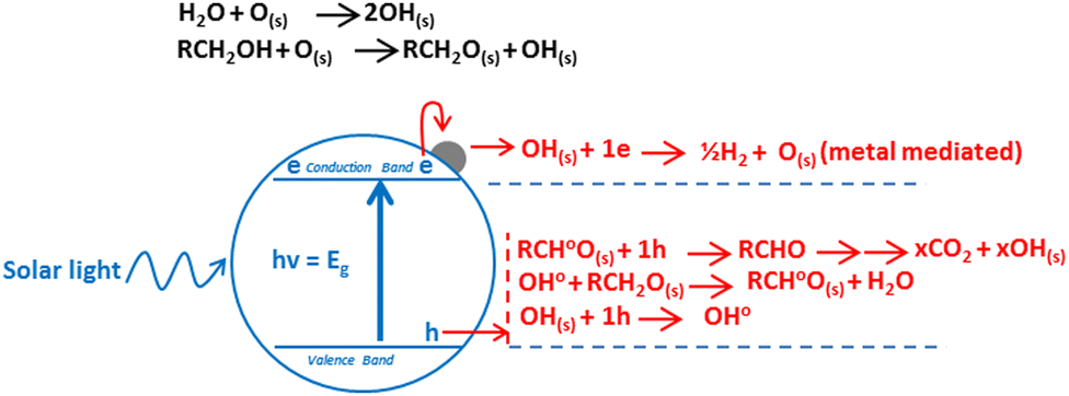 | ||
| Fig. 1 Mechanism of hydrogen production by oxygenate photoreforming. | ||
The transfer of charge to reactant can only occur when the charge carrier (electron) is higher in energy (or more negative in terms of electrochemical potential) than the electron acceptor, and the charge carrier (hole) is low in energy (more positive in terms of electrochemical potential) than the electron donor, thus allowing electron and holes flow.10 Photoreforming can become a cheap and versatile process for hydrogen production under mild conditions from biomass. Oxygenates such as ethanol are an interesting source of hydrogen (eqn (2)), as they can be considered both as a model substrate11 and as an industrial feedstock from waste or energy crops (cellulosic ethanol).
| C2H5OH + 3H2O → 2CO2 + 6H2 ΔG° = +137 kJ mol−1 | (2) |
From thermodynamic point of view, any semiconductor–organic molecule couple that satisfies requirements shown in Fig. 1 can be used for photoreforming. However, under realistic conditions other considerations including surface area, absorption coefficient, chemical stability, photo-corrosion, overpotential, electron–hole pair recombination rate and their mobility also become important.12 The reaction rate depends on how efficiently electrons and holes move to the surface of catalyst and subsequently transferred to the reactants at surface before they recombine.13–15 Thus, suitable surface and bulk properties are required for effective photocatalysis.16 Among many available photocatalysts TiO2, due to its inherent superior properties, promises to be the ideal candidate to compromise among these requirements. It is a large band gap semiconductor, with band gaps of 3.2, 3.02, and 2.96 eV for the anatase, rutile and brookite phases, respectively.17–21 Anatase and rutile have strong absorptions around 380 and 410 nm respectively, which can be calculated by formula λ = 1239.8/Ebg.22 Regardless of all its merits, TiO2 still struggles with its lower activity, which is mainly due to the rapid recombination of electrons and holes. One way to solve this problem is to modify TiO2 with metals. A five-decade research effort finally led to the realisation that an order of magnitude enhancement in the activity of TiO2 is required for any commercial application.23 In the following discussion, we will discuss the role of metals in reducing the electron–hole recombination and thus increasing the reaction rates.
Modifications of TiO2 photocatalyst has often been used to increase its photocatalytic activity by decreasing the recombination rate and extending the photoresponse into visible region. Loading of noble metal on TiO2 is more advantageous compared to other sensitization techniques such as dye molecules sensitization,24 since noble metal deposits are relatively stable even under photoirradiation in an oxidation environment.25–31 In general, there is an optimum loading concentration (less than 4 wt%), above which the observed photocatalytic activity decreases.32,33 Larger amount of metal leads to a drastic decrease on the photocatalytic activity which may have contribution from metal shadowing effects to reduce the light absorption by TiO2 and possibility that metal loading above the optimum value may cause the metal deposits to behave as recombination sites due to an excessive negative charge which can attract positive holes.34,35 In general, metals can increase the photocatalytic activity of TiO2 due to Schottky barrier formation or Surface Plasmon mechanism.
Schottky barrier formation mechanism
The highly improved separation of photogenerated charge carriers in TiO2 is achieved by the formation of rectifying Schottky barrier at the interface due to energy difference between the conduction band of semiconductor and work function of the metal.36–40 The Schottky barrier only allows the one way transport of electrons from bulk TiO2 to the noble metal e.g. Pt until their Fermi levels (EFs) are aligned and a thermodynamic equilibrium is reached (Fig. 2).14,41–46 When the catalyst is further exposed to light source, the photogenerated electrons can cause a shift of the EF of TiO2 to form a new quasi-Fermi level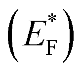 .47 At the same time, the previously formed thermodynamic equilibrium state is destroyed, and consequently the electrons continuously migrate from the TiO2 to the metal. By transfer of electron from semiconductor to metal the Fermi level of metal semiconductor composites shifts to more negative potential depending on the size and nature of the nanoparticles.48–51 Small size metal particles are more effective in upward shifting of Fermi level.52 A Fermi level shift from 20 mV for 5 nm to as large as 100 mV for 2 nm Au particles has been experimentally observed.52–54
 | ||
| Fig. 2 Charge distribution between TiO2–metal nanoparticles leading to equilibration with the C60/C60− redox couple, before and after UV irradiation. Reprinted with permission from American Chemical Society.52 | ||
Such a shift in the Fermi level enhances the efficiency of interfacial electron transfer to adsorbed species on the catalyst surface and causes a large build up in the capacitance of the Helmholtz layer and the diffuse double layer. The excess electron density remains mainly on the metal islands because the Helmholtz capacitance of the metal–solution interface is much higher than the space charge capacity of the metal semiconductor nanoparticles interface, even under accumulation contact.55 Hence, one can expect the metal Fermi level to shift close to the bottom of the semiconductor conduction band.52,54 Thus, H+ ions reduction to H2 over the noble metal surface is easier and more efficient than over bare TiO2.48,56,57 The work functions of the metals Pt, Pd, Au, Rh, Cu, and Ag are, 5.64, 5.12, 5.1, 4.98, 4.65, and 4.26 eV, respectively, and are larger than that of TiO2 (4.2 eV). The enhanced performance of Au, Pd and Pt towards photocatalytic H2 production during photoreforming may relate to their high work functions and thus Schottky barrier.58–60 These studies also elucidate the indirect role of metals in improving the charge separation as well as promoting the interfacial charge transfer kinetics in semiconductor photocatalysis.193,195
The height of the Schottky barrier at the Au/TiO2 junction decreased from 0.4 to 0.15 eV with the addition of more Au, from 0.25–2 wt%, according to the XPS examination of the valence band maxima. Because of this, compared to Au ensembles in TiO2 + 0.25% Au composite, visible-light-generated “hot electrons” in TiO2 + 2% Au composite must overcome a lower energy barrier during injection into the TiO2 support. Because they do not accumulate at the Schottky barrier, the “hot electrons” in the TiO2 + 2% Au composite are less accessible for recombination with the holes produced by visible light.61 It is found that the conduction band electron transfer from TiO2 to Au cocatalysts under ultraviolet light irradiation and the hot electron injection from plasmonic Au into the CB of TiO2 with the excitation of Au by visible light are both enhanced by the formation of the Au/TiO2(101) interface, which lowers the height of the Schottky barrier in comparison to the Au/TiO2(001) interface.62 Based on first-principles calculations, a thorough investigation of the effects of the interfacial structure and strain on the height of the Schottky barrier of the Pt/TiO2(001) interface has been conducted. The results of the interface adhesion energy demonstrate that two distinct interfacial structures, namely O–Pt bonding and Ti–Pt bonding, may exist experimentally for the Pt/TiO2(001) heterointerface. Additionally, the interfacial structures produce a range of heights for the Schottky barrier as well as variations in how the height of the Schottky barrier depends on strain. In-depth analyses reveal that the substantial dependence of the TiO2 band edges and the interfacial potential alignments on the structure and strain is the fundamental cause of these versatile modulations of the barrier height with the structure and strain. This suggests that these results are general and may be applicable to other metal/TiO2 heterostructures.63
Surface plasmon mechanism
Surface plasmon resonance (SPR) can be described as the collective excitation of valence electrons of metals oscillating against the restoring force of positive nuclei when the frequency of impinging photons matches the natural frequency of these electrons.64 The resonant photon wavelength is different for different metals.65,66 In case of metal–semiconductor–system it depends on many other factors discussed later.67–69 There are few known metals which exhibit resonance in the visible region; Cu, Au, Pd, Pt, and Ag. Among these metals Au and Ag are strong plasmonic metals and are mostly studied,70,71 while Pd and Pt have very weak surface Plasmon effects. Cu is also good SPR metal but it is not stable because of the formation of surface oxides.72 Surface Plasmon effect is shown by metals only in their zero oxidation state.73–75 SPR can enhance the concentration of charge carriers in the metal–semiconductor system and therefore the rates of photocatalytic reactions on the surface may occur by three mechanisms.Plasmonic noble metals nanostructures exhibit excellent mobility of charge carriers and have almost 105 times greater cross-section area than typical dye-sensitizer molecules. Furthermore, the ability to tune the resonance wavelength by changing the size or shape of nanostructures allows for the possibility of exploitation of entire solar spectrum.76 Both particle size and the embedding medium's refractive index have an impact on the wavelength of plasmon resonance.4,6–10,77–80 In comparison to smaller particles, the effective restoring force that the ions exert on the electrons is reduced in large particles because the surfaces are sufficiently separated from one another and the electrons require less energy to move from their equilibrium locations. One-dimensional nanostructures, in contrast to nanocubes, feature two dipole plasmonic peaks, one of which is associated with oscillating charges along the longitudinal axis and the other with oscillating charges along the latitudinal axis.77 These nanostructures' increased aspect ratio leads to a red shift in the dipolar longitudinal plasmonic peak as well as an increase in peak intensity. As a result, additional plasmons will be excited and their dipolar longitudinal plasmonic peaks' intensities will increase as well. For example, this phenomenon has been demonstrated both experimentally and theoretically (using the discrete dipole approximation) for silver nanobars, respectively.77
SPR-mediated charge injection mechanism
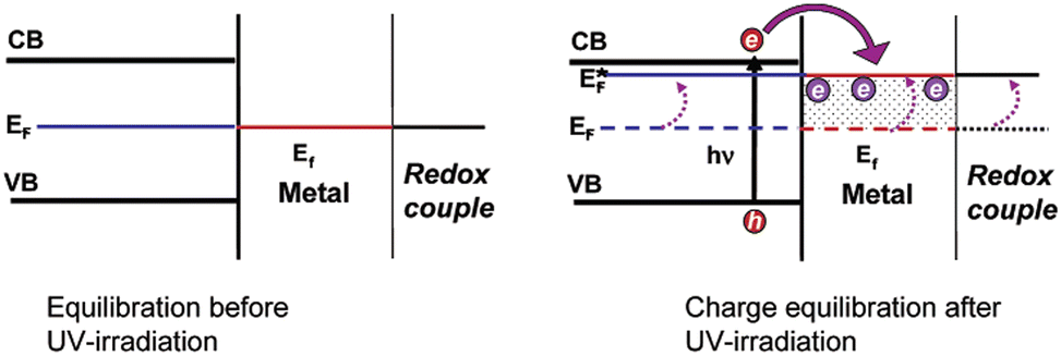
SPR-mediated electron injection mechanism also called hot electron injection mechanism from metal to semiconductor (M → SC) occurs when plasmonic metal nanoparticles and semiconductor are in direct contact with each other.25,81–87 This mechanism is analogous to dye sensitization. In oxide-supported Au nanoparticles were used to demonstrate the plasmon-induced dissociation of molecular hydrogen, a phenomenon that could only be explained by the production of hot electrons inside the metal.88,89 The characteristics of hot electrons in plasmonic nanostructures were then calculated in a number of theoretical investigations.90–92 The majority of experimental works on hot electron-driven photochemistry, however, use metal nanostructures in contact with semiconducting material, which further adds to the complexity of interpreting charge transfer and energetics.93 Using hybrid metal–semiconductor nanostructures, Park and co-workers demonstrated hot electron-driven CO oxidation and time-resolved transmission spectroscopy demonstrating hot carrier relaxation on pico-second time scales.94 Using a plasmonic Au/pGaN photocathode, DuChene and co-workers demonstrated hot hole-driven photoelectrochemical CO2 reduction.95Most semiconductors of interest for photoreforming are characterized by their conduction bands between −1.0 to 0.0 V and their valence bands between 2.0 to 3.5 V (electron energy band gap between 2.0 and 3.5 eV) on the NHE scale. For noble metal nanoparticles, the energetic electron formed in the process of the SPR excitation are in the energy window between 1.0 and 4.0 eV with respect to the metal Fermi level (0 V on the NHE scale). Owing to this alignment of the electronic states, in general the plasmonic metal/semiconductor systems may allow for the transfer of energetic electrons (hot electrons) from the metal to the semiconductor only and can execute reduction half-reactions on semiconductors, such as hydrogen evolution reaction (Fig. 3). It is worth mentioning that energetic holes retained on very small plasmonic–metal particles (particles of Au of ∼2 nm diameter), have sufficient energy to drive not only the photo-oxidation of most organic molecules, even much higher energy demanding water oxidation reaction on the surface of the metal.96 Rezvaneh reported that electron can only be transferred to TiO2 conduction band if the Au particle size is extremely small because the mean free path of electrons in metal particles is in the order of 1–2 nm, and hence, photoexcited electrons have a low probability to escape a larger sized particle.97 It is obvious to note that importance of each mechanism is governed by the geometric arrangements and optical properties of semiconductor and metal in the composite systems.71,98
 | ||
| Fig. 3 Mechanism of plasmon-induced charge transfer from metal to semiconductor. I, II and III are the electronic transitions from metal to proton. Adapted from ref. 99. | ||
Near field electromagnetic mechanism
Near field electromagnetic mechanism also called energy transfer mechanism is observed when plasmonic metal are large enough (larger than ∼50 nm in diameter) in size to generate the effective local electric field and there is a non-conducting conditions at metal/semiconductor interface preventing any direct exchange of electrons (Fig. 4).71,100,101 Electric field induced by photo-excited metal plasmonic nanostructures are few orders of magnitude higher than the field of photons used to photo-excite the nanostructure. These fields are spatially non-homogenous, with the highest intensity at the surface of the nanostructure and decreasing exponentially with distance from the surface within ∼20–30 nm and linearly further away. As a result of this the rate of electron–hole formation near semiconductor surface increases by a few orders of magnitude. The selective formation of charge carriers in the region of the semiconductor closest to the semiconductor/liquid interface rather than in the bulk of the semiconductor offers a few critical additional advantages; (i) they are readily separated from each other under the influence of the surface potential and (ii) they have a shorter distance to migrate to reach the semiconductor/liquid interface where photocatalytic transformations happens. This effectively means that the probability of photoreaction is enhanced relative to the probability of charge-carrier recombination.99 | ||
| Fig. 4 (a) Optical simulations showing SPR-enhanced electric fields owing to photo-excited Au particles, permeating into a neighboring TiO2 structure.102 (b) Proposed photocatalytic process for efficient hydrogen generation on Au–TiO2 nanostructures, based on near field LSPR under visible-light irradiation. Adapted from ref. 98. | ||
By combining strongly plasmonic metal nanoparticles (such as Ag, Au) with strongly catalytic metal oxide semiconductors (e.g., TiO2), redox electrochemical processes (including water splitting) have been shown to be enhanced by plasmon resonance.71,102–104 The original interpretation of these enhancement processes was based on the local field enhancement of sub-bandgap defect-mediated absorption in the TiO2 semiconducting material. These nanoscale metal/semiconductor systems were subjected to large-scale electromagnetic simulations using the finite difference time domain (FDTD) approach, which offered a high level of rigor. Several experimental studies, despite the great level of accuracy of these electromagnetic simulations, showed enhancement factors that were significantly larger than predicted by theory. For instance, Liu et al. reported a 66-fold increase in the photocurrent of an Au/TiO2 combination at a wavelength of 633 nm, or photon energy that is roughly half the bandgap of this material, exceeding that which can only be explained by simple local field enhancement.102
Photon scattering mechanism
The scattering of photons by plasmonic nanostructures increases the average photon path length in plasmonic metal–semiconductor composites causing an increased rate of electron–hole pair formation (see Fig. 5).105,106 Composite systems where plasmonic nanostructures are positioned to allow for numerous passes of resonant photons through the semiconductor matrix will exhibit very strong scattering effects.99 The near-field electromagnetic and scattering mechanisms are important for composite photocatalysts with an overlap between metal nanoparticle SPR and semiconductor absorbance bands.104 Ag/TiO2 composite systems are most suitable for this mechanism because Ag shows SPR band almost in the region where doped and bare TiO2 absorbs i.e. 400 to 500 nm.71,107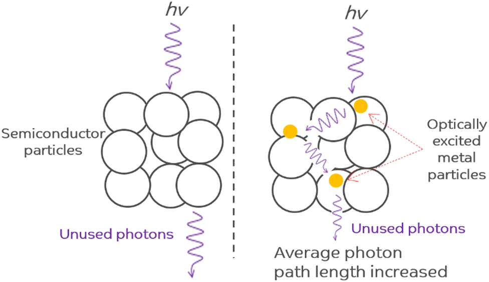 | ||
| Fig. 5 Photon scattering mechanism. Adapted from ref. 99. | ||
Photo-thermal effect
Photo-thermal effect has drawn some attention in heterogeneous catalysis where rate increase is observed in certain cases. On the basis of theoretical and fundamental research, postulated concepts were presented.108 In order to investigate the impact of the plasmonic resonance response on the reaction kinetics, we previously reported the photo-thermal reactions of ethanol over Ag/TiO2 in both steady state and ultrahigh vacuum conditions. We discovered that an increase in the reaction rate in 300–500 K temperature region was mostly due to changes in the activation energy whereas above this temperature range, the rise was caused by the pre-exponential component. The polarization of the reaction intermediates by plasmonic Ag particles, which leads to an increase in the reactivity, was suggested as a possible explanation for these findings.109 A consistently greater hydrogen to acetaldehyde ratio during photothermal reactions in the ethanol dehydrogenation reaction, reaching the stoichiometric ratio of one, as compared to thermal reactions, suggests that H2O generation competes with H2 synthesis thermally. In both thermal and photo-thermal reactions, the presence of Ag speeds up the rate of H2 evolution. This is linked to its role in H–H association reactions, in particular under light excitation which in turn might be linked to its plasmonic resonance effect (Fig. 6).107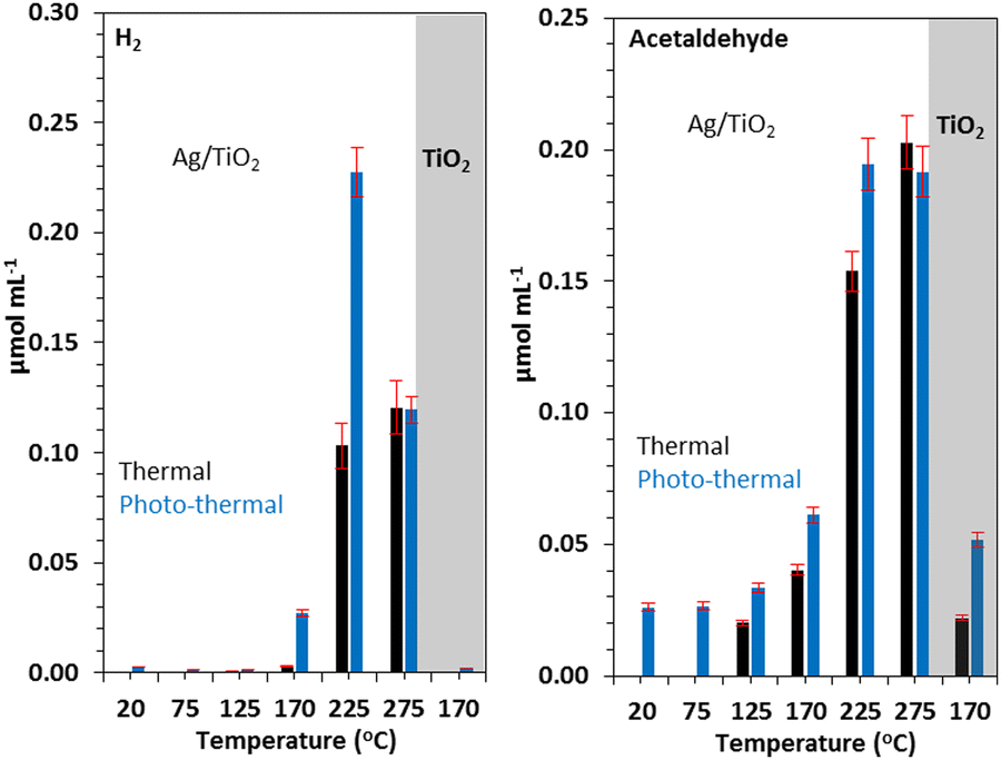 | ||
| Fig. 6 H2 (A) and acetaldehyde (B) production on similar amounts (31 mg) of TiO2 and 3 wt% Ag/TiO2 catalyst under thermal and photo-thermal conditions as a function of temperature at ethanol:N2 flow rate of 5.4 mL min−1. Reprinted with permission from Elsevier.107 | ||
Localized surface plasmon resonance (LSPR), as demonstrated by Upadhye and colleagues, can boost the reverse water gas shift reaction (RWGS) activity of Au/TiO2 and Au/CeO2 catalysts.110 The improvement was attributed to changes in the catalyst surface's intrinsic reaction kinetics, either through a hot electron production mechanism or an adsorbate polarization mechanism brought on by the LSPR. Tan and colleagues found that the catalytic performance of Au/TiO2 for ethanol oxidation increased by 50% and 100%, respectively, under visible light and UV irradiation in the photo-thermal regime (above 175 °C).111 Under UV illumination, the rate increase was attributed to both the photo- and thermal effects equally, whereas under visible light illumination, only the plasmonic-mediated electron charge transfer from the Au deposits to the TiO2 substrate was thought to be responsible. The photo-thermal catalytic oxidation of ethanol over TiO2 and a 1 wt% Pt/TiO2 catalyst was studied by Kennedy and colleagues. Increased levels of acetaldehyde created by photo-oxidation over TiO2 and its subsequent interaction with Pt metal, which results in CO2 synthesis by thermal reaction, appeared to be the main reason of the photo-thermal enhancement of CO2 production (70 percent at 100 °C).112
The interaction of methanol, triethanolamine, formic acid, and glucose on Pt/TiO2 was investigated by Song and colleagues. They claimed that the redistribution of Pt metal d-electrons to higher energy states was what caused the photo-enhancement in H2 generation.113 Chanmanee and co-workers investigated the alkane reverse combustion under photo-thermal conditions.114 They noticed that the generation of liquid hydrocarbons increased as the temperature rose. On the basis of each electron stored, an incident photon quantum yield (IPQY) of 0.02–0.05 percent was attained. Hu and colleagues used black TiO2 to study how temperature affected the visible light photocatalytic hydrogen generation from water and methanol.115 Due to the presence of Ti3+ states in TiO2 and an increase in the relative population of adsorbed methanol molecules in vibrationally excited states, the enhancement was attributed to the occurrence of visible light photocatalysis. Huang and colleagues have also proposed an improvement in the electron transfer probability and concurrent vibrational relaxation.116
Alternative models for the role of metal
The exact role of the metal is still disputed. In a recent paper, Zaera and coworkers presented a revolution in the role of metal in photocatalysis by introducing an alternative to the traditional approach, using the Au/TiO2 metal semiconductor as a reference system.117 They presented a new model in which protons from water are not reduced at the surface of the metal, a site physically separated from that on the semiconductor where oxygen production occurs. Instead, their data support a model in which the excited electrons promote the reduction of protons on the surface of the semiconductor, not the metal, and in which the reduced atomic hydrogen then moves to the metal and recombines to produce molecular hydrogen (Fig. 7).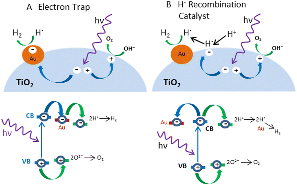 | ||
| Fig. 7 Schematic representation of the mechanisms (Upper) and electronic transitions (Lower) proposed to explain the role of metals (Au) in the photocatalytic splitting of water with semiconductors (TiO2). (A) In the conventional model, the metal acts as an electron trap that physically separates the excited electron used for proton reduction from the oxidation step that occurs on the surface of the semiconductor. (B) Alternative model proposes that H+ reduction occurs at semiconductor sites but that the resulting hydrogen atoms need to migrate to the metal to recombine and produce the final H2 product. Adapted from ref. 117. | ||
In this study, it was found that without the ability to facilitate the recombination of hydrogen atoms, the electron trapping functionality alone cannot enhance the photocatalytic activity of the TiO2 samples. Based on the widely accepted model for the role of the metal in photocatalysis, the focus was on finding cheaper electron scavengers. However, results show that a good catalyst for the recombination of atomic hydrogen is needed instead. For example, carbon black has been shown to be unsuitable for photocatalytic promotion despite its excellent conducting properties (the reason why it is often used as an electrode). On the other hand, nickel oxide, a material that cannot accept excited electrons from the conduction band of most photocatalysts, is nevertheless capable of enhancing their photoactivity. In general, the author believes that with a change of focus driven by this new proposed model, it may be possible to identify better promoters for photocatalysis in the near future.
Bowker and co-workers proposed a very different mechanism for the role of metal in the photocatalytic reforming of methanol on Pd/TiO2 catalysts.118–120 The key part of this was that the dehydrogenation of methanol on the Pd occurred even in the absence of light, but the reaction stopped because the metal surface was blocked with CO, which is strongly adsorbed on Pd. The role of light was to create an active oxygen state (probably O−) by absorbing light through band gap excitation in the TiO2. This oxygen was then in turn able to react with the poisoning CO to form CO2 and sustain the conversion of methanol. The oxygen vacancy in the TiO2 lattice was filled by the reduction of water to produce hydrogen (Fig. 8). It is likely that the mechanism in the case of Au/TiO2 is different from that of Pd/TiO2. CO is much weaker bound to the Au surface due to the low energy of the d orbitals in Au. Therefore, the blocking surface intermediate of methanol is probably different from that of Pd. The species in question could be methoxy or formate.
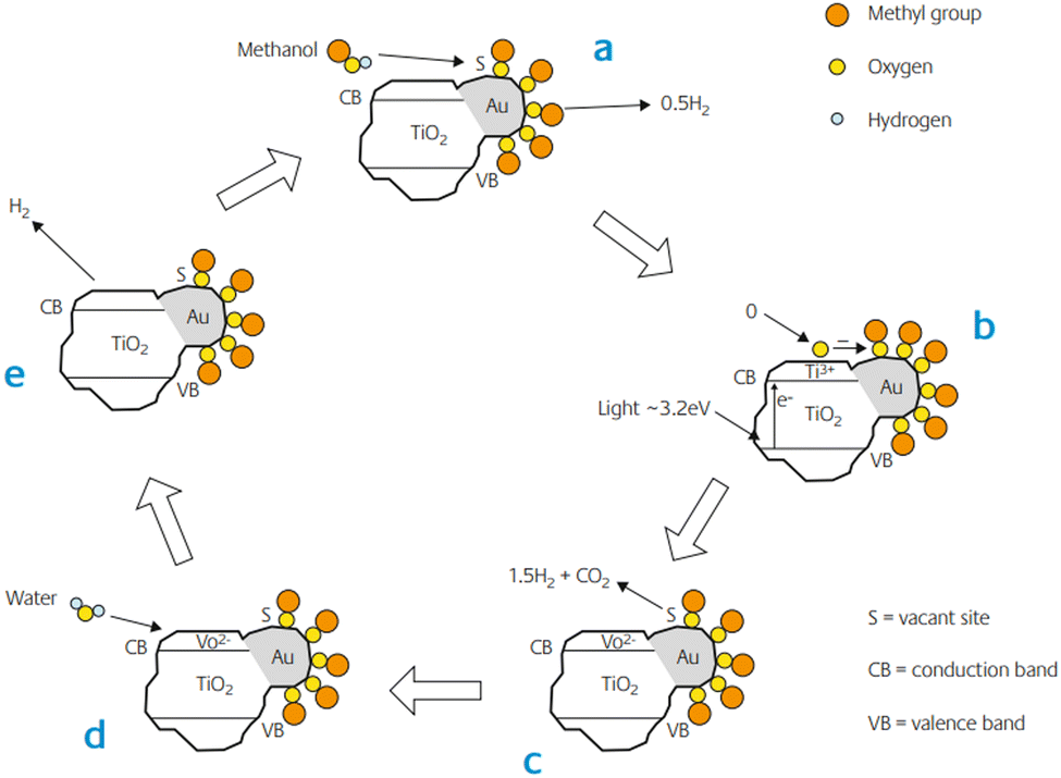 | ||
| Fig. 8 The proposed mechanism of anaerobic photocatalytic reforming of methanol on Au/TiO2. Here we show the methoxy as the pivotal intermediate in the reaction, though it could be the formate. Adapted from ref. 121. | ||
They showed from TPD, that format is the intermediate in Au/TiO2, at least in an oxidising environment, leading to the simultaneous desorption of CO2/hydrogen from the surface at ∼200 °C, a property not present in TiO2 alone. Boccuzzi and co-workers have identified both intermediates on Au/TiO2 catalysts by infrared measurements.122 Whether the methoxy or the formate is the key intermediate, it has been suggested that this intermediate is destabilised in the presence of light, possibly by reaction with excited species on the support. It was also found that methoxy intermediates also existed on the TiO2 support.122 However, these were more stable than those on the gold, produced other products (methane, CO and water) and do not appear to be affected by the presence of gold nanoparticles. Thus, they are probably spectators in the course of photocatalysis, since TiO2 alone does not produce such products.
Pt/TiO2: a typical benchmark
Platinum (Pt) is the most frequently used metal to modify the TiO2 photocatalyst surface because of its suitable work function,123 the smallest over-potential for H2 evolution,15,124–127 higher intrinsic platinum activity in reductive processes,128 high activity due to smaller size (but not too small), presence of optimum electron trapping Ti3+ sites in Pt than Au loaded TiO2,129 and facilitation in the discharge of electrons from semiconductor nanoparticles into the electrolyte by forming an ohmic contact which accelerates H2 production from water in the presence of a sacrificial electron donor.125,130 Usually, the optimum amount of Pt loading on TiO2 P25, a well-known reference photocatalyst, is 0.5 wt%.131–133 It is Pt(111) face that come in contact with anatase TiO2 (101) face to form the Pt–TiO2 interface. The perpendicular alignment between the (111) lattice planes of Pt and (101) lattice planes TiO2 enhance charge transfer due to better matches than the parallel alignment which makes a distorted Pt–TiO2 interface (Fig. 9). An optimum Pt particle size is required for optimum activity. For Pt nanoparticles of about 1 nm size no injection of electrons takes place due to higher metal Fermi level whereas when the particles are too large, the Fermi level of metal is low enough that in addition to electrons, holes can also be injected from the VB of TiO2 into the nearby energy state of the metal, hence facilitating charge carrier recombination.134,135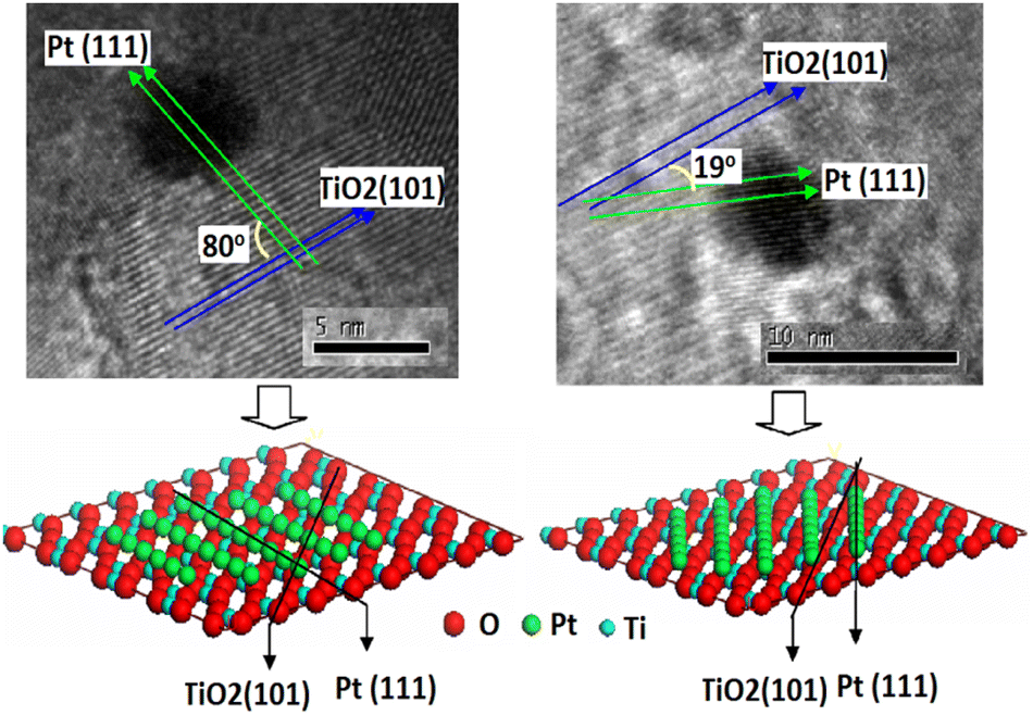 | ||
| Fig. 9 High-resolution TEM images of (a) perpendicular (b) parallel; with speculated metal–support interface. Reprinted with permission from Elsevier.136 | ||
It has been reported that the photocatalytic H2 evolution activity of Pt/TiO2 samples is closely related with the valence state of Pt cocatalyst.137 Metallic Pt nanoparticles may have little contribution to H2 evolution because of too high adsorption energy.138,139 One of the major drawbacks of photo-reforming on Pt/TiO2 is the favorable thermodynamics for water oxidation back reaction at room temperature under atmospheric pressure.140,141 Addition of different electrolytes including NaOH, Na2CO3 and NaI in the reaction mixture is one of the effective methods to inhibit the back reaction on Pt surface as explained in (Fig. 10 and 11).142–145
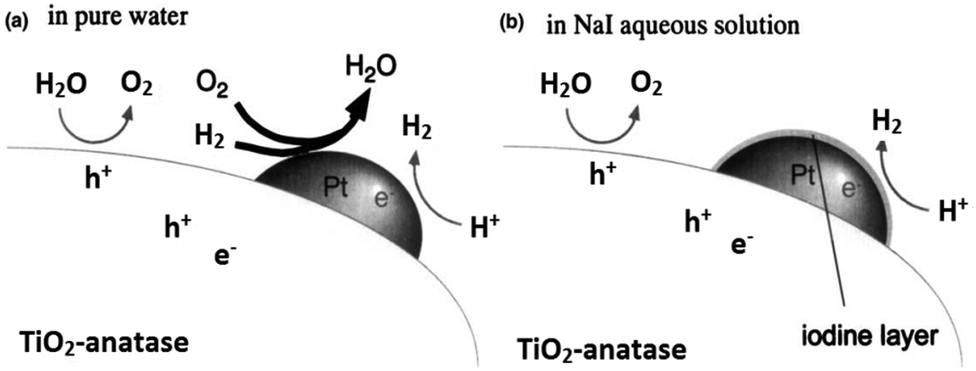 | ||
| Fig. 10 Speculated reaction mechanisms over Pt–TiO2; (a) in pure water (b) NaI aqueous solution. Reprinted with permission from Royal Society of Chemistry.145 | ||
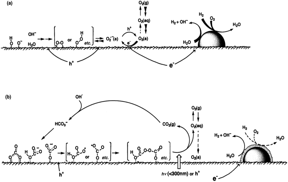 | ||
| Fig. 11 Speculated reaction mechanism over Pt/TiO2; (a) in water and (b) in carbonate salt aqueous solution. Reprinted with permission from Royal Society of Chemistry.143 | ||
Gold/TiO2: a recent benchmark
Electrochemical,146 photochemical48,147 and spectro-electrochemical148,149 experiments have shown that the gold nanoparticles readily accept electrons from a suitable donor or an electrode. These electrons can be further used to reduce H+ to 1/2H2 when photoexcited TiO2 is used as an electron donor. According to some reports, complete photocatalytic decomposition of water is possible using Au as compared to Pt where back reaction of H2 and O2 can be avoided on the former.150 Au/TiO2 nanocomposites exhibit two operating mechanisms including UV or visible light for water splitting depending upon the wavelength of excitation.UV light mechanism
In the UV irradiation the efficiency of charge separation is improved by the transfer of electrons from TiO2 to Au nanoparticles due to the formation of Schottky barrier.45,151 Sreethawong and co-workers compared the reactivity of Au, Pd and Cu loaded anatase TiO2 for hydrogen production and found the reactivity order as Au > Pd > Cu.35 However loading of gold nanoparticle decreases the photocatalytic activity for the decomposition of the organic compounds due to the reduction of the surface OH groups.152 Morphology of the gold particles in Au/TiO2 photocatalysts has a direct effect on the photocatalytic activity. It has been reported that spherical or hemispherical gold particles are more active than rod shaped particles.150,153–155Visible light mechanism
Gold surface plasmon excitation (SPR) is another mechanism responsible for the visible light driven water splitting reaction on the Au/TiO2 photocatalyst.81 This effect is characteristic of relatively smaller Au nanoparticles in metallic Au(0) state.73,74 Gold nanoparticles (5–50 nm) absorb in the visible range from 500 to 600 nm due excitation of surface plasmons and may inject hot electrons into the conduction band of TiO2.71,156 Electrons in the TiO2 conduction band and holes in gold nanoparticles may have appropriate potential to produce hydrogen and oxygen from water due to reduction and oxidation reaction respectively. Larger gold nanoparticles possess stronger plasmonic resonance which leads to more-intense plasmonic near-fields and hence higher optical absorption in the TiO2 for efficient photocatalysis. Gold nanoparticles (50–70 nm) in the Janus nanostructures has been reported photocatalytically more active due to their stronger plasmonic near field effect.98 The position, intensity and shape of the plasmonic band seen in the absorption spectra depend on various factors including particle size and morphology, loading amount, calcination temperature, dispersion, interparticle distance, and the dielectric property of the surrounding medium.68 Gold nanoparticle <2, 2–50 and >50 nm show very nominal absorption band (almost flat), a strong absorption band in the region 520–530 nm and a wide absorption band to include the whole visible range respectively.157 Obviously the mechanism of photochemical process indicated in Fig. 12 is an oversimplification since it has been demonstrated that there is a charge re-distribution between the gold nanoparticles and the semiconductor which causes a shift of semiconductor Fermi level toward more negative potentials.54,82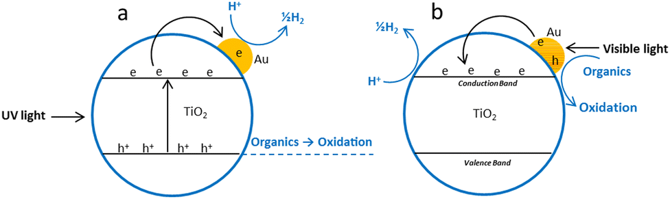 | ||
| Fig. 12 Proposed photoreforming mechanism over Au/TiO2; (a) under UV light irradiation (b) under visible light irradiation. | ||
Au/TiO2 photonic crystals
Photonic crystals (PCs) are a periodically structured electromagnetic medium through which light cannot propagate linearly.158 PCs can localize, trap, provide multiple paths and magnifies light intensity at the plasmonic wavelength of the metal particles and thus enhance the SPR of the metal nanocrystals, ultimately leading to enhanced visible light hydrogen production from photo-reforming at TiO2. The development of appropriate techniques to create artificial photonic crystal structures has received substantial attention because of their outstanding optical properties. Here, colloidal self-assembly technology,159,160 precision machining, nanolithography,161–163 and layer-by-layer method are the basic photonic crystal fabrication techniques.164Gravity, capillary forces, or the electric and magnetic droved deposition process are the main means of achieving the self-assembly method of colloidal crystals, also known as the bottom up method. Through this technique, photonic crystals with a vast area of compact arrangement and uniform particle size can be constructed.165,166 Regarding the precision machining method, sets of holes are drilled into solid slab or wafer surfaces using chemical beam-assisted ion etching to produce PCs.167 The photonic crystal with the photonic forbidden band has a lattice constant up to millimeters in the microwave band, as shown by the machining technique. When constructing PCs using the layer-by-layer method, a 1D rod layer with a stacking sequence that repeats every four layers is typical. The rods are parallel and maintain a set pitch to one another in a repeating unit. Additionally, between neighboring layers, the rods' orientation is 90 degrees rotated.168
Zhang and co-workers synthesized unique Au loaded highly porous photonic crystals (PCs) layer of TiO2 by facile anodization procedure in which plasmonic wavelength of Au matches the photonic band gap of the TiO2 PCs (Fig. 13).169 Under visible light illumination (>420 nm), the designed material produced a photocurrent density of ∼150 μA cm−2, which is the highest value ever reported in any plasmonic Au/TiO2 system under visible light irradiation. This work contributes to the rational design of the visible light responsive plasmonic photocatalytic composite material based on wide band gap metal oxides.
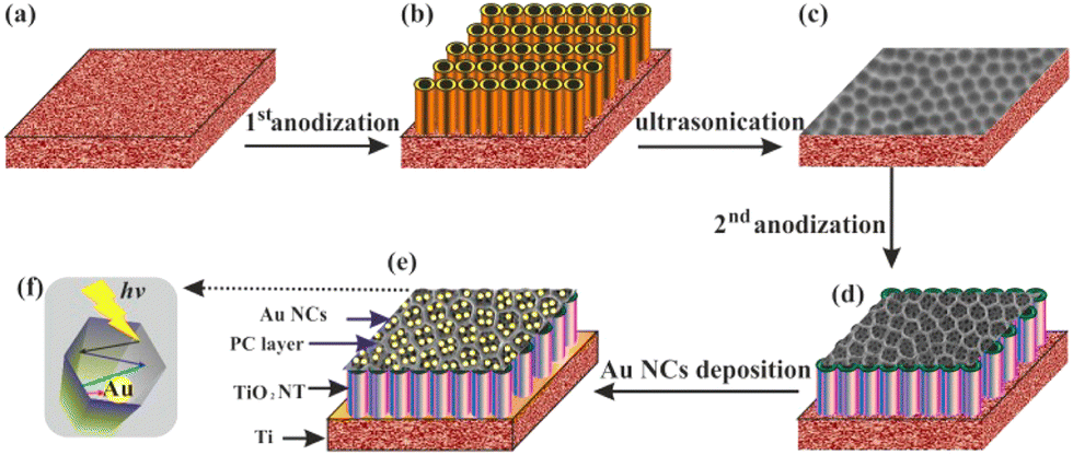 | ||
| Fig. 13 Schematic diagram of the Au/TiO2 nanotubes photonic crystal (NTPC) fabrication procedure: (a) Ti foil, (b) anodization, (c) nano imprints on the Ti foil after ultrasonication (d) second anodization, (e) Au nanocrystals deposited on the TiO2 (NTPC) via photocatalytic reduction; (f) top of view of (NTPC) layer for light trapping and enhancing SPR of the Au nanocrystals. Reprinted with permission from American Chemical Society.169 | ||
Recently, Idriss and coworkers fabricated three dimensionally ordered macroporous, inverse opal TiO2 based Au/TiO2 and Au–Pd/TiO2 photocatalyst having photonic band gapes (PBG) centered at 357 nm coinciding with electronic band gape of TiO2 and 580 nm coinciding with surface plasmon resonance of gold.170 They noted that the Au/TiO2 with the PBG position close to its electronic band gap is 2 to 3 times more active. The highest performance was found for the Au–Pd/TiO2 with PBG of 360 nm. High rate of hydrogen production was attributed to suppressed e–h recombination due to the co-incidence of the photonic band gape (357 nm) with the electronic band gape (385 nm) of TiO2 (Fig. 14).
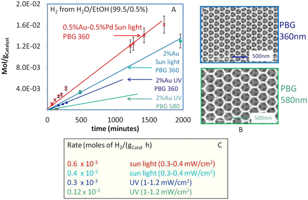 | ||
| Fig. 14 (A) Hydrogen production from photoreforming of ethanol using photocatalysts with two different PBG positions under UV light with flux about 1–1.2 mW cm−2 and under direct sun light with UV flux of about 0.3–0.4 mW cm−2 (B) SEM images of the two PBG Au/TiO2 photo-catalysts (C) Hydrogen production rates (C). Reprinted with permission from Springer Nature.170 | ||
Pd/TiO2: a future benchmark
Palladium (Pd) is the cheapest and most commonly used metal among the noble metals (Pt, Pd & Au) as co-catalyst with the TiO2 photocatalyst,60,171,172 and the cost of Pd metal is approximately 20–25% of that of platinum (Pt) metal.173 Theoretically, larger the difference between the metal's work function and that of TiO2, larger the height of the Schottky barrier formed at the TiO2 surface. Hence, platinum (Pt) should be more effective than palladium (Pd) or gold (Au) in accepting conduction band electrons of TiO2, and therefore should exhibit high H2 production activity. Recently, palladium (Pd) is emerging as an efficient metal cocatalyst compared to Au and Pt for proton reduction site because the density of states in the vicinity of the Fermi level is higher for Pd than for Pt and Au with the Fermi level of Pd being ∼0.2 eV higher than the Fermi level of Pt (−10.8 eV).174,175 Pd also has an optimum Schottky barrier height and a much lower electron affinity and hence electron trapping capability which may enable more facile electron transfer from Pd for proton reduction.174 Additionally, high surface area offered by the Pd due to the porous nature of metallic Pd may also contribute to its high activity.176 Su and co-workers probed the kinetics of the photogenerated electrons on metal–semiconductor photocatalyst systems and found that a fast proton reduction occurs on Pd/TiO2 as compared to Au/TiO2.177 It was revealed that Pd shows a slow reverse transfer process of electrons from metal to TiO2 (low krev) for the trapped photogenerated electrons. Since Pd most likely provides an ohmic contact, whereas Au shows capacitive properties. It is likely that a combination of the above factors is important to the superior performance of the Pd/TiO2 relative to Pt/TiO2 or Au/TiO2 for hydrogen production through photo-reforming of oxygenates. There are some others reports in literature where Pd is used as cocatalyst over TiO2 for hydrogen productions reactions.58,60,171,173Alkaline earth metal oxide (AEMO), usually regarded as structural promoters, can also promote the photo-catalytic activity of TiO2 by raising its Fermi level.178,179 It was also reported that the AEMO incorporated into M/TiO2 stabilizes the size of metal nanoparticle by making an alkaline earth metal, noble metal and Ti metal mixed oxide layer at metal–TiO2 interface. This layer acts as glue at metal–TiO2 interface thus preventing sintering.180,181 Our group recently explored the role of alkaline earth metal oxides in palladium supported TiO2 photocatalysts. It was observed that very high rates of hydrogen production can be achieved by the introduction of AEMO in metal supported TiO2 photocatalysts.51,182 Alkaline Earth Metal Oxides (AEMOs) promoted electron transfer from the TiO2 surface to palladium nanoparticles by raising Fermi level of TiO2 (from EF to  ) and the conduction band level (from ECB to
  ) due to more negative potential for SrO/TiO2 support as compare to TiO2 alone (Fig. 15). It was found in XPS studies that palladium nanoparticles were exclusively in metallic state due to close proximity of highly electropositive AEMOs (SrO, BaO) which is highly beneficial for palladium to act as proton reduction sites. Yang and Co-workers also described such promotion of electrons transfer from SrO/TiO2 surface to active metal sites by the elevation of Fermi level for rapid CO oxidation reaction.183
 | ||
| Fig. 15 Schematic illustration of electron transfer between Pd and AEMO-TiO2. Reprinted with permission from American Chemical Society.182 | ||
Non noble metal supported TiO2
Precious metals are expensive and rare, which makes their future doubtful. Therefore, it makes sense to develop substitutes that are free of precious metals. Ni and Cu as substitute have been studies in this regard.184–186 Although all reported hydrogen generation rates over these photocatalysts are still low from an economic and practical point, however, they are strong candidates to replace highly expensive Pt and Au co-catalysts for solar H2 production. Some of the important work related to role of these metals in photoreforming is discussed.Cu2O/TiO2
Cu2O is one of the few p-type direct band gap (2.0–2.2 eV) semiconductors which are inexpensive, nontoxic and readily available.35,187–195 The coupling of Cu2O with TiO2 not only enhances the photocatalytic activity of TiO2 but also extends the optical response from UV to visible range. Cu2O/TiO2 composites systems having appropriate energy levels with respect to both oxidation and reduction of water are reported to produce hydrogen under visible light irradiation.139,196–200 Cu2O as a p-type semiconductor when combines with a n type semiconductor (TiO2) makes a hetero-junction of type II-staggered in Cu2O/TiO2 composites. When visible light is supplied to this nanocomposite, electrons in the conduction band of p-type semiconductor will be thermodynamically transferred to the conduction band of n-type semiconductor and holes remain in the valence band of p-type semiconductor. In the presence of metal such as Au and under UV irradiation, both electron and hole can transfer from TiO2 to Cu2O (Fig. 16).201,202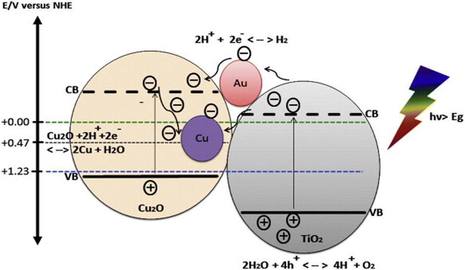 | ||
| Fig. 16 Energy band position of Cu2O and TiO2 aligned with redox potential of water. Reprinted with permission from Elsevier.210 | ||
The migration of photogenerated charge carriers can also be promoted by the inner electric field established at the heterojunction interfaces also known as space charge regions.203–206 Consequently, the recombination rates of photogenerated charge carriers will be greatly suppressed which is resulting into high photocatalytic activity.201,207 Sinatra and co-workers observed 10 times greater rate of hydrogen production over 2% Au–Cu2O/TiO2 than 2% Au–TiO2 from glycerol water mixtures due to the synergetic effect of the Cu2O/TiO2 p–n junction and noble metal nanoparticles.208 Cu2O/CdS nanostructures were also reported to have superior photocatalytic hydrogen production from water splitting due to type II hetero-junction formed at the Cu2O/CdS interfaces.209
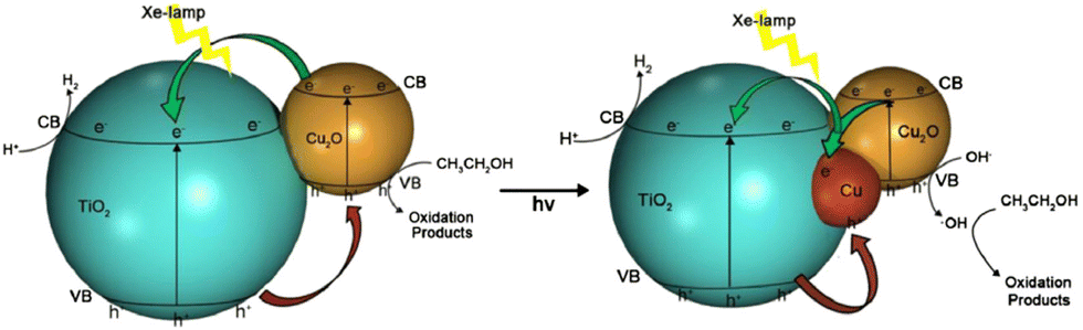
Zhang and co-workers studied that the deposition potential during electrodeposition of Cu2O on TiO2 nanotubes array (TNA) has direct effect on the morphology and visible light hydrogen production activity of as prepared Cu2O/TiO2 nanotubes array photocatalysts.211 Cu2O electrodeposited at −0.8 V had maximum exposed (111) facets and was found to have better photocatalytic activity (42 times) for hydrogen production from water–glycerol mixture. Among (110), (111), (200) and (220) planes of cubic Cu2O, (111) facet is the most stable and is proposed to hinder oxidation of Cu1+ to Cu2+. Xi and co-workers demonstrated that Cu2O/TiO2 photocatalyst prepared by glucose solvothermal method generated 16 times greater hydrogen form ethanol–water mixture than P25 under visible light due to the reduction of a part of Cu2O to Cu0 and the synergistic effect of Cu2O and Cu (Fig. 17). The photogenerated electrons first transferred to Cu and then to the conduction band of TiO2, which enhanced the lifetime of photogenerated charge carriers. As a result of this synergistic effect hydrogen evolution rate on Cu2O/Cu/TiO2 was twice as on Cu2O/TiO2.212
 | ||
| Fig. 17 H2-Production mechanism form photoreforming of ethanol using Cu2O/Cu/TiO2 under Xe-lamp irradiation. Reprinted with permission from Elsevier.212,214 | ||
Lalitha and co-workers reported the highest rate of hydrogen production to date from 5% glycerol water system under solar light irradiation over Cu2O/P25 photocatalyst. However, the mechanism of charge dynamic was not clear in their study.213 Very recently our group deposited highly dispersed Cu–Cu2O nanoparticles over TiO2 by using metal organic frameworks as templating agents to prevent agglomeration of Cu ions as it happens when metal salt is used. It was observed that Cu2O was reduced to metallic Cu due to the rise of TiO2 conduction band electrons Ef level under continues UV excitation, and under visible light Cu2O established the p–n junction where only electron transfer occurred from Cu2O to TiO2. In both cases hydrogen production rate was very encouraging.214
CuO/TiO2
CuO deposited over TiO2 has been found to markedly enhance hydrogen production activity as compared to pure TiO2,199,215–217 even sometimes more than noble metal based photocatalysts.218 A considerable negative shift in Fermi level of the CuO by the transfer of electrons from TiO2 is responsible to gain the necessary potential for hydrogen production on CuO. Decrease in hydrogen production rates over Cu/TiO2 photocatalyst with time is attributed to the adsorption of sacrificial reagents oxidation products over photocatalyst active surface and due to decrease of Cu contents due to drop of pH by the formation of CO2. A decrease in Cu content from 9.1 to 8.1 mol% has been observed due to Cu leaching at 5.6–4.6 drop in pH. Gombac and co-workers prepared unique design of catalyst by covering the CuOx with porous TiO2 using water-in-oil micro-emulsion method for hydrogen production from organic species. The superior activity of this system was due to the combined effect of fine Cu/CuOx dispersion and possibility of some Cu incorporation into the TiO2 lattice. Stability tests under reducing conditions in the presence of a sacrificial agent indicate that copper leaching was marginal. Major issue confronted while using Cu and Ni as cocatalyst is the formation of agglomerates which enormously reduce the hydrogen production rates. In this context, a remarkable breakthrough was brought by Young and Co-workers who deposited the highly dispersed Cu nanoparticles for the first time by complex precipitation method.219 In this innovation Cu–glycerol complex was developed which was later precipitated by strong alkali. It has been also validated later that bulk CuO has positive conduction band potential than H+/H2 redox couple. However, smaller CuO nanoparticles have different electronic band structure and conduction band potential becomes negative compared to H+/H2 redox couple due to quantum confinement effect.220–222Idriss and co-workers explored above results further by depositing the Cu nanoparticles over TiO2 by following the method as described by the Young and Co-workers. They found that the activity of CuO/TiO2 was found to depend on the nominal CuO loading, with 1.25 wt% CuO being optimal (H2 production rate = 20.3 mmol g−1 h−1 in 80![[thin space (1/6-em)]](https://www.rsc.org/images/entities/char_2009.gif) :20 EtOH:H2O).223 At this loading amount, a highly dispersed sub monolayer Cu(II) species on TiO2 surfaces rather than supported CuO nanoparticles were proposed as the active site for hydrogen production. The Fermi level for such adsorbed species is positive with respect to the TiO2 conduction band but negative than H+/H2 redox couple. For CuO nanoparticles of size ∼3–4 nm, the band gap is around 2.3–2.6 eV as compared to bulk CuO, Eg ∼ 1.3–1.5 eV. As the CuO nanoparticle size increases, the conduction band of CuO becomes positive with respect to H+/H2 redox couple, preventing direct transfer of electrons from CuO to H+ and H2 formation is suppressed accordingly. The inactivity of bulk CuO for H2 production can be explained using the same rationale (Fig. 18). These results have also been confirmed by latest research by Jung and co-workers. At an optimum Cu loading of 0.5 wt% the CuOx was present as relatively highly dispersed fine nanoclusters. At Cu loadings beyond 0.5 wt% a bimodal distribution of CuOx deposits appeared with the prevalence of larger Cu deposits increasing with increasing Cu content.224 Our group recently described another method to deposit highly dispersed Cu nanoparticles by using metal organic frameworks (MOFs).225 A Cu based MOF was first deposited over TiO2 then as prepared composite was calcined at various temperatures to get highly dispersed Cu nanoparticles. In this study intermediate carbon was proved helpful in reduction of Cu2+/Cu0 during calcination process.
:20 EtOH:H2O).223 At this loading amount, a highly dispersed sub monolayer Cu(II) species on TiO2 surfaces rather than supported CuO nanoparticles were proposed as the active site for hydrogen production. The Fermi level for such adsorbed species is positive with respect to the TiO2 conduction band but negative than H+/H2 redox couple. For CuO nanoparticles of size ∼3–4 nm, the band gap is around 2.3–2.6 eV as compared to bulk CuO, Eg ∼ 1.3–1.5 eV. As the CuO nanoparticle size increases, the conduction band of CuO becomes positive with respect to H+/H2 redox couple, preventing direct transfer of electrons from CuO to H+ and H2 formation is suppressed accordingly. The inactivity of bulk CuO for H2 production can be explained using the same rationale (Fig. 18). These results have also been confirmed by latest research by Jung and co-workers. At an optimum Cu loading of 0.5 wt% the CuOx was present as relatively highly dispersed fine nanoclusters. At Cu loadings beyond 0.5 wt% a bimodal distribution of CuOx deposits appeared with the prevalence of larger Cu deposits increasing with increasing Cu content.224 Our group recently described another method to deposit highly dispersed Cu nanoparticles by using metal organic frameworks (MOFs).225 A Cu based MOF was first deposited over TiO2 then as prepared composite was calcined at various temperatures to get highly dispersed Cu nanoparticles. In this study intermediate carbon was proved helpful in reduction of Cu2+/Cu0 during calcination process.
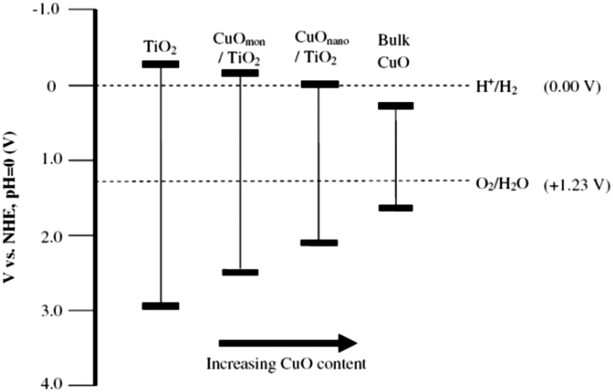 | ||
| Fig. 18 Band gap energies for TiO2, CuO and CuO/TiO2 photocatalysts with respect to CuO loading. Reprinted with permission from Elsevier.223 | ||
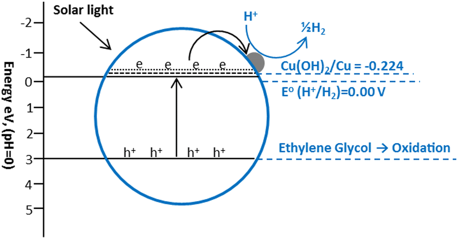
The Cu(OH)2/TiO2 systems have recently shown some good results for hydrogen production. Yu and co-workers fabricated Cu(OH)2/TiO2 photocatalysts using the deposition precipitation using NaOH and reported a hydrogen production rate of 3.4 mmol h−1 g−1 in a 0.09 M ethylene glycol solution under UV irradiations.226 The potential of Cu(OH)2/Cu, (Cu(OH)2 + 2e = Cu + 2-OH, E° = −0.224 V) is slightly lower than conduction band (−0.26 V) of anatase TiO2 and higher than the reduction potential of H+ (2H+ + 2e = H2, E° = 0.000 V), which favors the electron transfer from the CB of TiO2 to Cu(OH)2 which causes the reduction of Cu2+ to Cu0 nanoclusters (Fig. 19). These Cu0 clusters promote the transfer of photo-generated electrons from the conduction band of TiO2 to reduce H+.184,185
 | ||
| Fig. 19 Proposed mechanism of hydrogen production from ethylene glycol over Cu(OH)2 loaded TiO2. | ||
In general, the systems where metal in loaded during TiO2 synthesis step from its precursors outperform the impregnated systems that used either ethanol or glycerol as sacrifice molecules, demonstrating better hydrogen production rates.227 By photodepositing Cu on the surface of TiO2 supports, active and affordable nanocomposites can be created. TiO2 structural characteristics have a significant impact on its activity, for example, highly defective surface results in a very high dispersion of the metal and a higher activity for H2 production due to an increase in the oxidation rate of the sacrificial agents. While solar-like radiation causes a significant portion of the Cu to be oxidized and prone to photocorrosion, UV light only causes little leaching.228 After a few hours, the concentration of Cu ions stabilizes, indicating that an equilibrium has been reached between the leaching phenomenon and the Cu photodeposition process. Surprisingly, there is little of a detrimental impact on hydrogen generation.228 Cu2+ ions partially enter the TiO2 structure in CuOx/TiO2 nanocomposites made via copper photodeposition, which causes oxygen vacancies to form and alter the band gap while also creating traps for photogenerated holes and electrons. Compared to liquid-phase procedures, gas-phase processes provide higher H2 productivity and, in particular, higher selectivity (approximately 92–93%) to acetaldehyde.229
Ni/TiO2
Recent studies have shown that nickel is a good choice for the preparation of active TiO2-based catalysts for hydrogen production compared to other transition metals. However, the mechanism behind the enhancement of photocatalytic activity is more complex. Different mechanisms have been proposed depending on the type of nickel such as Ni, NiO or Ni(OH)2. Yu and co-workers deposited Ni(OH)2 nanoclusters on TiO2 by a simple precipitation method and observed a hydrogen production rate of 3.0 mmol h−1 g−1 in 25 vol% aqueous methanol under UV excitation.230 The hydrogen evolution was attributed to the more positive redox potential of the Ni2+/Ni (E° = −0.23 V) pair compared to the conduction band of TiO2 (E° = −0.26 V) which served as active sites for the reduction of H+ to H2 (Fig. 20).231 In another study, it is postulated that Ni(OH)2 is converted to NiO after prolonged irradiation in the oxidizing environment of the reaction mixture.117 There is some controversy in the literature about the valence and conduction band energies of NiO.232 Values in the range of −0.3 to −1.0 eV are reported for the conduction band and 2.4 to 4.3 eV for the valence band (with respect to SHE).233 Thus, NiO cannot capture photogenerated electrons from the conduction band of TiO2 because the conduction band of NiO is more negative than that of TiO2. However, theoretical calculations show that H:H recombination on NiO(100) is exothermic, with an activation barrier of only 40 kJ mol−1.234 The high hydrogen production rates observed on NiO/TiO2-containing catalysts can be explained by the ability of NiO to act as a site for recombination of adsorbed atomic hydrogen after H+ has accepted an electron directly from the conduction band of TiO2.117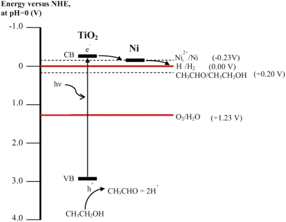 | ||
| Fig. 20 Schematic illustration of important electron transfer processes in the Ni/TiO2 system leading to H2 production. Reprinted with permission from Elsevier.231 | ||
Fujita and co-workers reported that the loading of p-type NiO over n-type TiO2 conductors produces a p–n hetero-junction, which generates an internal electric field at the NiO/TiO2 interface.235 It was proposed that this field accelerates electron transfer for proton reduction at the NiO, thus strongly suppressing the recombination of photogenerated electrons and holes. With reference to some studies it was found that highly dispersed and exclusively metallic Ni particles are excellent hydrogen production sites.231 Recently, the hydrogen production activity of a series of Ni/TiO2 photocatalysts in ethanol–water mixtures was investigated.236 It was found that the photocatalytic activity of Ni/TiO2 photocatalysts strongly depends on the Ni zero oxidation state and loading, with a loading of 0.5 wt% is optimal, giving a hydrogen production rate of 24.3 mmol h−1 g−1 in 95 vol% aqueous ethanol under a UV flux equivalent to sunlight (about 4–5 mW cm−2). This high activity of the Ni/TiO2 photocatalyst was attributed to the Fermi level of Ni0, which is positive with respect to the conduction band of TiO2 and negative with respect to the H2O/H2 redox couple. The high work function of nickel is also advantageous in preventing the back migration of electrons, since an excellent Schottky junction formed at this interface. In the same work, 0.63 wt% NiO/TiO2 was tested. A long induction period observed before a constant hydrogen production rate was reached, which was about a quarter of that of Ni/TiO2. This induction period was explained by the in situ reduction of part of the NiO to Ni0 by the hydrogen produced in the initial phase of the reaction. The Fermi level of Ni0 is below that of the conduction band of TiO2 anatase.
Bimetallic TiO2
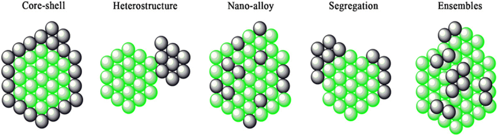
Bimetallic heterogeneous catalysts are widely employed in many fields of catalysis, due to high performances; increased activity and selectivity to desired products, extended lifetime arising from the cooperative interactions between the two metals.237–247 Heterojunction is formed when two different materials with varied work functions (or electron affinity) are in electrical contact with each other. The surface energy of the metal and combined metals, dissociation energy, standard reduction potential, bond enthalpies, miscibility, metal–metal and metal–TiO2 lattice interactions, and reduction kinetics of the metals results in the various configurations:243 (1) distribution of both the metals over the TiO2 surface; (2) core–shell structure of the metals decorated over the TiO2 (and vice versa) and (3) alloy-like structure dispersed over the TiO2. The type (3) enables the effective interaction of both the metals with one another as well as with TiO2. Type (2) provides suitable platform for metal–metal interactions and that the metallic core may not have substantial interactions with titania. The induced internal electric field at the interface between the metal–metal and metal–titania redistributes the charge density and charge carriers drift directionally along the electric field force.243 However, direction of electron transfer between the interface metal atoms is difficult to determine owing to the different bonding environments, and bonding situation at the interface is very complex because of shorter interfacial spacing and multiple layers of atoms.243It is well known that the work function of a given metal decreases by alloying with other metal with a lower work function. This suggests that alloying of other metal with Pt would decrease the work function of Pt nanoparticles, Pt is having highest work function among noble metals. This may raise Fermi level potential of metal and promote efficient electron transfer from TiO2 to metal nanoparticles. The bimetallic deposited TiO2 may exhibits some unique characteristics properties which are different than that of mono metallic due to the synergistic effect between the monometallic counterparts. For example, when the Pt–Cu co-modified TiO2 is used as a photocatalyst, nitrate can be selectively reduced to N2 under irradiation. In contrast, nitrate is mainly converted to ammonia or nitrite over the Pt modified TiO2 or the Cu modified TiO2, respectively.248 Similarly, highly selective ammonia synthesis from nitrate can be observed in the presence of the Pd–Cu co-modified TiO2 while only as small amount of NO3− is converted to ammonia in the presence of the Pd-modified TiO2.249 The use of bimetallic catalysts for hydrogen production through photo-reforming has started very recently. Only a few bimetallic systems, namely Au/Pd core–shell nanoparticles,177,250 Au/Pt Nano-alloys251–253 immobilized on TiO2 and polymer protected Pt/Ru bimetallic clusters254 have been investigated for H2 production. The structure of bimetallic nanoparticles can range from core–shell (cherry) structures to bimetallic hetero-structures, (nano) alloys, intermetallic etc., as shown in Fig. 21.
 | ||
| Fig. 21 A pictorial representation of bimetallic nanoparticles structures. Reproduced with permission from John Wiley and Sons.255,256 | ||
:1). Later on Pedro and co-workers provided further information to establish the optimal metal amount and proportion between Pt and Au.253 In their work the photocatalytic photo-reforming of Au–Pt Nano-alloys, deposited on P25 TiO2 was compared under UV, visible and simulated solar light irradiation, both in the presence and absence of methanol as a sacrificial electron donor. When UV light was used for excitation, photons were mainly absorbed by TiO2 and then the presence of a large percentage of Pt in the Nano-alloy was beneficial because it accelerates hydrogen evolution through fast proton reduction. In contrast, when using exclusively visible light, photons ware absorbed by Au nanoparticles and in this case, the presence of Pt was detrimental when hydrogen evolution is not the controlling step. Under simulated sunlight the situation was balanced between visible light absorption and faster hydrogen evolution by the presence of optimal Au and Pt content in the Nano-alloy. Optimum loading of both the metals was 0.25 wt% in each case, with most active photo-catalysts containing, 70–100% Pt in UV, 80–100% Au in visible and 78%Au–22%Pt in the simulated solar irradiations.
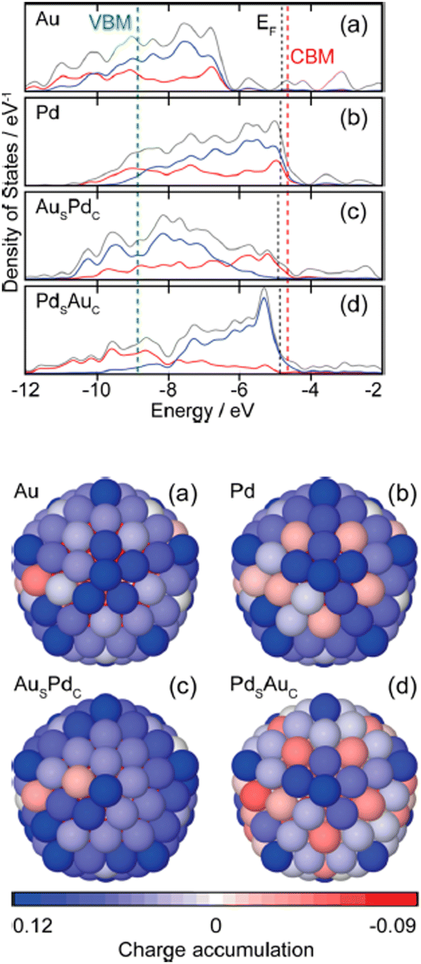 | ||
| Fig. 22 (a–d) Electronic density of states (DOS) profiles of 147-atom icosahedral clusters of Au, Pd, AusPdc, and PdsAuc, respectively. The total valence DOS (gray) is complemented by the contributions of the d-orbitals in both the core (red) and outer shell (blue) region. EF of the metal clusters, conduction band minima (CBM), and valence band maxima (VBM) of TiO2 are indicated by black and red dashed lines, respectively.261 27B (a–d) Charge localization from the view of the (100) surface of 147-atom icosahedral clusters of Au, Pd, AusPdc, and PdsAuc, respectively. The blue and red colors represent atoms with electron accumulation and depletion, respectively. Reprinted with permission from American Chemical Society.177 | ||
The work functions of Cu and Ni are 4.94 eV268 and 5.15 eV,269 respectively, and the work function of bimetallic Cu–Ni is at the level between Cu and Ni. As a result, a more appropriate height of Schottky barrier was obtained between TiO2 and Cu/Ni alloy than between TiO2 and the single metal. Recently, our group has prepared bimetallic Cu/Ni hydroxide-supported TiO2 photocatalysts for hydrogen production from alcohol–water mixtures. The mechanism of hydrogen production via Cu/Ni hydroxide supported TiO2 has been discussed in detail. It was proved that Cu(OH)2 is reduced to metallic Cu by the conduction band electrons of TiO2 due to a suitable redox potential, but Ni(OH)2 cannot be directly reduced by the conduction band electrons of TiO2. Thus, when the pH of the reaction mixture falls to 4 after one hour of photoreaction, the Ni(OH)2 dissolves as free Ni2+ ions, which can now be thermodynamically reduced by the conduction band electrons of TiO2 to metallic Ni and deposited as a separate proton reduction site or via electron-rich Cu to form a Cu/Ni alloy (Fig. 23).267 The stability of these systems is a crucial issue that requires adequate understanding. Long-term performance needs to be assessed even though no one has reported any stability issues. Since strongly reducing conditions preserve the metal in its metallic state and keep it stable under photoreaction conditions, it is commonly accepted that non-Nobel metals are stable systems.226,227,264,265,267
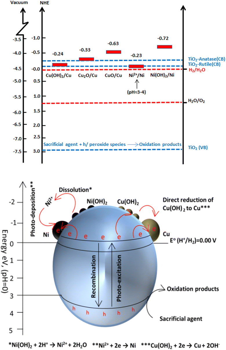 | ||
| Fig. 23 Schematic illustration for hydrogen production, charge transfer, separation and chemical conversions in Ni(OH)2 and Cu(OH)2 nano-clusters modified TiO2 system under photoreaction conditions. Reprinted with permission from John Wiley and Sons.267 | ||
Metal loading methods
Metal loaded photocatalysts are usually prepared using photodeposition,139,270 impregnation,13,271,272 photoreduction and chemical reduction with H2 or NaBH4.139,270,273 Photodeposition method is most widely used to load due to its easy handleability, high-efficiency and repeatability and in most cases this method yields more active photocatalyst.274,275 This is in line with the rational that metal is preferentially deposited on semiconductor sites with high electron density under photoreaction conditions. On the other hand the impregnation method includes impregnation of TiO2 with the Pt precursor solution, drying, and finally reduction at ca. 500 °C.135,276 Although this method is simple, easily manipulated and all of the metal in the solution is used but results in lower activity due to greater particle size.277 Other methods including sonochemical reduction method by prolonged sonication,278 plasma-enhanced impregnation method to improve the dispersion of Pt, modified conventional impregnation method by utilizing glow discharge plasma,136 have also been employed.Photocatalysis by supported single metal atom
As was previously discussed, cocatalysts, particularly noble metal particles, are important to be deposited onto semiconductors in order to improve charge separation and modify the kinetics of surface reactions.8,279 However, the low exposed number of metal atoms and the weak interaction between the metal and support significantly restrict the catalytic activity of particle-based cocatalyst systems. Since only the atoms on the surface of metal particles are involved in catalytic processes,11 reducing the size of metal particles to a single atom is an efficient way to get around this problem.280–282 Furthermore, since metal atoms act as the catalytic centres, improving the loading density of individual metal atoms will improve catalytic performance even further (Fig. 24). In addition, single atom photocatalysis offers the following intriguing advantages over its bulk, nanoparticle, and nanocluster equivalents: (i) Due to their unique electronic structures and unsaturated coordination centers, they exhibit high activity and selectivity;283,284 (ii) a significant decrease in the use for catalytic metals;285,286 (iii) simple to understand reaction mechanisms due to single-atom reactive sites;287,288 and (iv) an excellent platform to understand the structure–performance correlation based on their atomic-level structures.289,290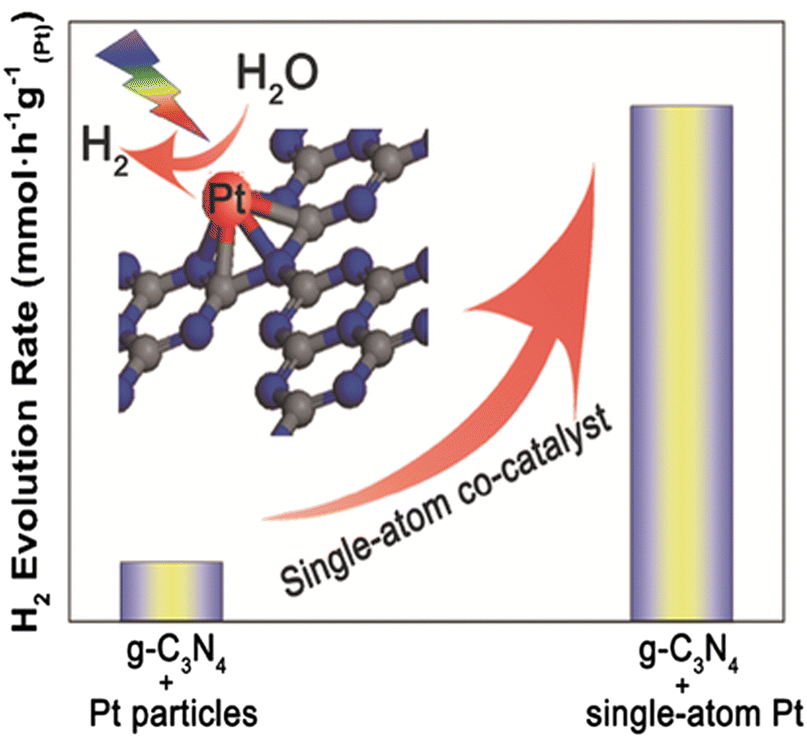 | ||
| Fig. 24 The highly stable single-atom co-catalyst (Pt) embedded in the sub-nanoporosity of 2D g-C3N4 leading to significantly enhanced photocatalytic H2 evolution activity. Reprinted with permission from John Wiley and Sons.286 | ||
The creation of an effective approach to stabilize the loading of high density metal atoms on the support photocatalyst is the key. The stability of single-atom photocatalysts depends on interactions between the metal and the support. In these interactions, the metal atoms are often stabilized by nearby surface atoms or ligands on the support, preventing their diffusion and aggregation.291 Strengthening the impact of the metal–support interaction on single-atom photocatalysts is a common approach for designing and producing single-atom-based photocatalysts.292 This is typically accomplished through the modification of the supporting materials, such as anchoring surface sites (defects and vacancies), heteroatom doping, coordinating with organic bridging ligands, and anchoring on metal–organic frameworks.291
Therefore, before using the support in photocatalytic reactions, it is important to choose and modify it. There has only been few studies where Single atom supported semiconductors have shown improved performance for H2 production from photoreforming of organics. Given its potential and advantages over conventional metal-supported photocatalysts, we anticipate that this system will have a high potential for photoreforming applications because of its inherent advantages as discussed above. It may also contribute to an increase in activities to the point where they are sufficient to support industrial scale applications.
Role of surface face
It is well known that anatase (001) facet is more active than (101) and (100) facet because of its higher surface energy and is more reactive for dissociation of water molecules.293–301 Surface hole stability trends in rutile and anatase are (100) < (110) < (011) < (001) and (011) < (100) < (001) respectively.293–301 Surface hole trapping levels of TiO2 with the exception of (100) rutile are well above the valence band edge (3.0 V [NHE]) and thus stabilized (less reactive). For instance a hole stabilization on anatase (001) of 1.3 eV reduces the oxidative power to ca. 1.7 V [NHE]. But at the same time this hole stability with respect to the bulk value is a large driving force for hole transport to the surface and enhances the equilibrium surface hole density by 1020 at room temperature.302 The hole diffusivity of anatase TiO2 at room temperature is known to be about 4 × 10⁻⁵ m2 s−1.303 Based on these results, it is believed that the fast hole decay process mostly reflects the trapping of holes that are excited near the surface. While the slow decay process corresponds to trapping and/or recombination processes of the holes that are excited inside the particle. Yu and co-workers performed Pt loading on fluorinated anatase nanosheets with 75% exposed (001) facets by photochemical reduction deposition method. Surface fluorination was useful to stabilize the high energy (001) facets. A very good rate of hydrogen production was observed by the synergistic effect of surface fluorination, exposed (001) facets and Pt loading.304 The experimental results and density functional theory calculations reveal that holes and electrons tend to reach and react at the same surface sites, i.e., crystal edge/corner, owing to the exposed (001) and (101) facets of TiO2.305 These findings offer insights into the nature of photocatalytic active sites and imply an activity-based strategy for rationally engineering catalysts for improved photocatalysis, which could be also applied for other catalytic materials.Dye sensitized TiO2
Another method to boost activity in the visible range is to sensitize metal-supported TiO2 using dyes.306 The most important criteria when choosing a dye is to make sure that it will not be photooxidized by TiO2.11 The various steps for producing H2 on such systems are depicted in Fig. 25. In the H2 photocatalytic production, a number of rationally designed donor–acceptor dyes can be utilized as sensitizers. The reaction process, the way dye interacts with organic materials, and the structural and electrochemical characteristics of the sensitizers all affect the rate of H2 generation. The photocatalytic process may be hampered by charge recombination between injected electrons in TiO2 and the oxidized dye if dye regeneration is slower, based on the molecular structure and electronic characteristics of the dyes.307,308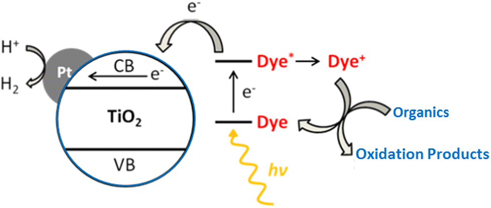 | ||
| Fig. 25 Schematic illustration for hydrogen production, on dye sensitized Pt/TiO2 system under photoreaction conditions. Reproduced with permission from John Wiley and Sons.306 | ||
Therefore, an increase in electron density on TiO2 can aid increase hydrogen generation rates by boosting light harvesting efficiency in conjunction with a greater driving force for electron injection. Accordingly, in order to provide the best results, the molecular design of sensitizers should be carefully adjusted based on the specific organic (and set of conditions) employed in the experiments. A breakthrough in dye-sensitized photocatalytic H2 production sustainability may result from precisely calibrated sensitizers, broadening the spectrum to a variety of organics and perhaps biomass-derived feedstocks.307,308 Dibranched donor–(π–acceptor)2 dyes have been investigated as photosensitizers in the photocatalytic production of H2 in conjunction with a Pt/TiO2 catalyst. Phenothiazine, cyanoacrylic acid and mono-/poly-cyclic fused thiophene π derivatives serve as donor core, acceptor/anchoring group and light harvesters, respectively. The dyes optical and electrochemical characteristics can be improved by carefully designing thiophene-based spacers. These thiophene-based sensitizers show increased stability after longer irradiation times and improved performances in terms of H2 production rates and light-to-fuel efficiencies.309,310
Au/TiO2 superstructures
One of the most difficult missions is to find suitable materials as photocatalysts that can not only harvest the full spectrum of solar light, from ultraviolet to near-infrared (NIR) region, but also achieve high and efficient solar-to-hydrogen conversion. Catalysts and effective optoelectronic devices have been developed using metal–semiconductor nanocomposites. These performance of such nanocomposites is greatly impacted by the electrical and morphological properties of the metals and semiconductors they are made of. Novel nanocomposites containing plate-like anatase TiO2 mesocrystal superstructures and noble metal (Au, Pt) nanoparticles preferentially photodeposited on the edge of TiO2 mesocrystals have been prepared. The findings showed that the majority of photogenerated electrons could move from the dominant surface to the edge of the TiO2 mesocrystal, with reduction reactions primarily taking place at {101} facets (Fig. 26). This allowed for a significant (more than one order of magnitude) increase in the photocatalytic reaction rate in organic degradation reactions. The charge recombination of these electrons with the holes in the Au NPs is greatly inhibited by this anisotropic electron flow, increasing the visible-light photocatalytic activity. Compared to conventional TiO2 nanocrystal samples, these exceptional characteristics considerably minimize the amount of Au or Pt loading on the TiO2 mesocrystal while maintaining the same photocatalytic activity.311,312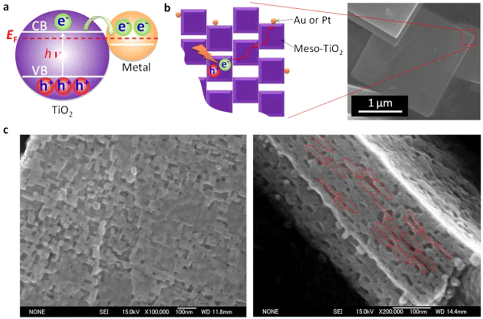 | ||
| Fig. 26 Diagrammatic representation of (a) electron transfer from noble metal (Au, Pt) nanoparticles to TiO2 upon UV light exposure. (b) The transfer of electrons on Au or Pt/meso-TiO2. Meso-TiO2 is constituted of an orderly alignment of anatase TiO2 nanocrystals, as shown in the SEM picture in panel b. Meso-TiO2 typically has dimensions of 2–5 um and a thickness of 50–300 nm. (c) SEM pictures of the Meso-TiO2 basal (left) and lateral (right) surfaces. Reprinted with permission from American Chemical Society.311 | ||
Au nanosphere, mono-encapsulated in TiO2 hollow nanosphere, and three-dimensionally assembled array of these Au–TiO2 show multiscattering effect and exhibit a significantly higher photocatalytic activity of H2 generation than Au–TiO2 (3.5 folds under visible light irradiation and 1.4 folds under solar light irradiation). The longer light path length caused by multiscattering between Au–TiO2 and reflection inside the TiO2 shell accounts for the 3D-increased array's activity. As a result, the nanosphere has a greater chance to absorb light, and more hot electrons are anticipated to be produced by the electron transfer from the Au nanosphere to the TiO2 shell, increasing the formation of H2.313 A wide solar response photocatalyst was developed employing Au/La2Ti2O7 sensitized with black phosphorus, and optimum H2 generation rates of around 0.74 and 0.30 mmol g−1 h−1 at wavelengths longer than 420 nm and 780 nm, respectively, have been reported. The increased photocatalytic activity in the visible and NIR light ranges is a result of the extensive absorption by black phosphorus and plasmonic Au. It was proposed that the strong photoactivities found were caused by the effective interfacial electron transport from excited black phosphorus and Au to La2Ti2O7.314 The above-mentioned outcomes offer us a new viewpoint on building structures that effectively utilize light and considerably enhance photocatalytic activities due to their unique structure as compared to conventional photocatalytic materials.
Catalyst benchmarking
Although the focus of this review is on the qualitative effects of different factors on photoreforming, it is crucial to talk about how important it is to describe the results in photocatalysis with clarity. A catalyst's activity is often measured in terms of the amount of reaction happened over a certain period of time per unit of catalyst material (weight, surface area, or volume), turnover frequency (TOF), apparent quantum yield (AQY), and solar to hydrogen (STH) efficiency. Due to its specificity to pure water splitting, STH is perhaps the most crucial metric yet is frequently reported inaccurately for reactions including sacrificial agents.Reporting rates of product generated by the total mass of catalyst is a typical practice in trying to define the benefits of photocatalysts. An analysis of the catalyst activity may be erroneous as a result of this prevalent practice of reporting activity. By measuring the rate over the catalyst's surface area, it is possible to demonstrate that the enhancement of activity seen in reporting reaction rate per unit mass, particularly for multicomponent catalysts, may in fact be due to simple geometric factors. When normalized by mass, it was discovered in a research of Au/TiO2 photocatalysts for H2 evolution that the micro- and nanostructured catalysts showed a substantial variation in activity.315 We recommend authors to include both data reporting processes. Although this does not completely eliminate all the variables that could affect the actual catalysis (since not all of the surface is guaranteed to be illuminated, the surface area should also be combined with a complete morphological analysis of the material porosity), we think it would be a more reliable way to report activity. Surface area normalization, on the other hand, has a more academic sense.
In fact, part of the potentially active surface during photocatalytic tests is not illuminated due to shading (scattering and reflection), not participating in the catalysis. Therefore, the efficiency must be somehow connected to the percentage of light that the catalyst actually uses. Due to this, the term apparent quantum yield (AQY), which describes the quantity of incident photons of a specific wavelength per unit of time and volume that enter the photoreactor, has been developed.316 Recently, models that can better accommodate more complex photocatalytic materials, including heterojunctions, were presented. These models allow the QY (or AQY) to be derived from reaction rates under simulated solar or polychromatic light.317 If monochromatic light is utilized for the AQY evaluation, the wavelength selection must be as compatible as possible with the optical characteristics of the photocatalyst.318 Reporting the AQY determined with a single monochromatic light source may be deceptive if the catalyst can absorb light of various wavelengths. Last but not least, the as-calculated quantum yield should include all experimental information in addition to the wavelength used, such as the reactor's shape and the precise length of the catalytic experiments on which the number of moles of product and the number of photons were counted; the latter is important because the rate of product formation might not be constant over time.
In recent publications, comparison tables featuring cutting-edge catalysts are showing up more frequently. If you choose them carefully, rationally, and fairly, they will be more beneficial. These tables should compare as many performance parameters as possible, not just one. The stability and selectivity of the catalyst, two equally significant parameters of comparison, cannot be fully understood by reporting merely a comparison of quantum yields. Since the period of the experiment is chosen arbitrarily for the purpose of calculating the yield, it is easy for the authors to influence it for their own convenience and lose impartiality, especially when the rates of product production are not constant. Additionally, a catalyst with a higher QY or AQY may only be artificially superior because it does not exclude the possibility that other unobserved mechanisms contributed to the developed product (parallel experiments in the dark under same conditions of temperature, catalyst loading, etc. must be invariably carried out).319
Conclusions and future work
There is debate on whether the metals act as electron sink and H recombination center or recombination center alone.117,315 Regardless it is important to prepare extremely small metal particles (high dispersion) to increase the photo-reforming rate per gram of catalyst. Strategies to produce metal single-atom catalysts in the heterogeneous catalysis field can be adopted and utilized. In general, the rate of H2 production increases with an increase in metal loading. The maximum amount of H2 production is observed in metal% loading between 1.5–3 wt%.11,279,315 Beyond this loading, a decrease is observed. This decrease is often ascribed to the metal shadowing effect. Keeping this in mind, a catalyst with metal nanoparticles containing only a few atoms and uniformly distributed on the surface seems the way to go. However, it is very difficult to prepare the high dispersed metal catalysts. There are few studies in which appropriate metal particle sizes were carried. Puskelova and co-workers synthesized highly porous TiO2–Pt aerogel composites by mixing sol–gel synthesized TiO2 with Pt colloidal suspension followed by supercritical drying and subsequently annealing at 500 °C. Metal particle size was tuned by adding tri-sodium citrate. The hydrogen production rate was enhanced due to more reactive Pt sites of smaller tunable particles and higher support surface area.320 Recently Naldoni and co-workers demonstrated that adsorption of metal particles followed by the reduction with NaBH4 was a superior method than others to develop intimate contact and a very fine degree of dispersion.129 Li and co-workers prepared visible light active photocatalyst by mixing Pt/TiO2 with luminescence material Er3+:Y3Al5O12 which can absorb visible and infrared light in solar spectrum and emit ultraviolet light to fulfill the requirements of TiO2 for water reduction. This technique may provide an effective way of harvesting solar energy for large scale hydrogen production in future.321–324 Further work must be conducted on improvements in the efficient and affordable preparation of single atom supported semiconductors. For instance, it can offer the much more catalytic sites possible while also limiting the shadowing effect among other advantageous qualities as previously discussed.Among all the catalysts studied for photoreforming so far, TiO2 offers more advantages in terms of industrial applications than any other catalyst. However, TiO2 can absorb only less than 5% of sunlight because of its wide band-gap. Various strategies, the most prominent of which is TiO2 doping have long been researched as almost all the dopant help to increase visible light absorption. However, there is not much promise in this strategy because dopants are detrimental to photoreforming rates as they create defects that act as recombination centers. Li and co-workers prepared visible light active photocatalyst by mixing Pt/TiO2 with luminescence material Er3+:Y3Al5O12 which can absorb visible and infrared light in the solar spectrum and emit ultraviolet light to fulfil the requirements of TiO2 for water reduction. This technique may provide an effective way of harvesting solar energy for large-scale hydrogen production in the future.185,321–323 Since black TiO2 not only absorbs photons across a wide spectral range (UV to IR region), but also modifies the structural and morphological features, along with the electronic properties of the material, significantly improving the catalytic performance, the associated drawbacks of white TiO2 and its modified forms were addressed to a large extent after its discovery.325 The synthesis procedures required, though, are laborious and challenging. With increased knowledge of its electronic structure and stability under reaction conditions, additional research with the goal of producing black TiO2 under milder, less energy-intensive conditions may help further improve its activity.326
It appears that H2 production using TiO2 based catalyst has reached its plateau and there is only a marginal increase in rates. Further work needs to be focused more on fundamental understanding using state-of-the-art facilities that bring progressive improvement in capabilities. Electron–hole recombination is a critical problem that has, so far, limited the efficiency of the most promising photocatalytic materials. Apart from metal, the electron–hole recombination can be reduced by carefully designing the geometrical structure of semiconductor particles to allow anisotropic migration of electrons and holes. For, example, H2 production from alcohols in uniform, one-dimensional brookite TiO2 nanorods is highly enhanced by engineering their length. The hole and electron diffusion lengths in TiO2 are about 10 nm and several micrometers, respectively.327 The holes are effectively confined to the width of the nanorods, whereas electrons are free to move over the whole length, due to their 1D nature.328 For these reasons, the high H2 production rate of the long rods with the delocalization of electrons along their 1D structure, favors electron−hole separation and carrier extraction by protons and the alcohol.329 Chong and co-workers recently reported hydrogen production by Cu doped TiO2 films with preferred (001) orientation by the RF magnetron sputtering method.330 They concluded that Cu dopant not only induced the slight transformation of anatase to rutile phase but was also useful to synthesize TiO2 films with preferred high energy (001) facets.331 Water molecules can easily dissociate on the (001) facet which will enhance the transfer of photogenerated charge carriers from films to water molecules.332–334 Cu(I) species can effectively prevent the recombination of charge carriers by trapping the photogenerated electrons. Further investigations in this direction are needed, that may be help to enhance overall photcatalytic activity in synergy with loaded metals.
Even after decades of research on TiO2, water oxidation reaction kinetics has not been improved. There is a need to understand why the kinetics of water oxidation is slow although this reaction is thermodynamically more favorable as compared to its reduction. Studies focused on water oxidation reaction understanding may provide answers. Recently Idriss and co-workers studied the water oxidation reaction using cerium(IV) cations as sacrificial agents using Ir/TiO2 catalyst.335 More similar works are needed to understand the kinetics and thus enhance the reaction rates. Further investigation of photonic crystals can help enhance the H2 production from photo-reforming. At the moment the work is at its initial stages and suffers from low activities mainly due to the impurities added into the structure during the preparation of photonic crystals. Further TiO2 photonic crystals have defect states that need to be eliminated without destroying photonic crystals structure. These impurities decrease the activity considerably by providing e–h recombination centers.169,170
Author contributions
All the authors contributed in writing this manuscript. The corresponding author conceptualized and supervised writing of the manuscript.Conflicts of interest
There are no conflicts to declare.Acknowledgements
The authors of this work acknowledge the resource support from all the institutions listed under author(s) affiliation.References
- M. Ni, M. K. H. Leung, D. Y. C. Leung and K. Sumathy, Renewable Sustainable Energy Rev., 2007, 11, 401–425 CrossRef CAS.
- J. Schneider, M. Matsuoka, M. Takeuchi, J. Zhang, Y. Horiuchi, M. Anpo and D. W. Bahnemann, Chem. Rev., 2014, 114, 9919–9986 CrossRef CAS PubMed.
- N. Rahimi, R. A. Pax and E. M. Gray, Prog. Solid State Chem., 2016, 44, 86–105 CrossRef CAS.
- A. J. Haider, Z. N. Jameel and I. H. M. Al-Hussaini, Energy Proc., 2019, 157, 17–29 CrossRef CAS.
- M. T. Noman, M. A. Ashraf and A. Ali, Environ. Sci. Pollut. Res., 2019, 26, 3262–3291 CrossRef CAS PubMed.
- C. Y. Toe, C. Tsounis, J. Zhang, H. Masood, D. Gunawan, J. Scott and R. Amal, Energy Environ. Sci., 2021, 14, 1140–1175 RSC.
- S. Banerjee, J. Gopal and P. Muraleedharan, et al. , Curr. Sci., 2006, 90, 1378–1383 CAS.
- A. K. Wahab, M. A. Nadeem and H. Idriss, Front. Chem., 2019, 7, 780 CrossRef CAS PubMed.
- M. A. Nadeem, K. A. Connelly and H. Idriss, Int. J. Nanotechnol., 2012, 9, 121–162 CrossRef CAS.
- A. V. Puga, Coord. Chem. Rev., 2016, 315, 1–66 CrossRef CAS.
- M. A. Nadeem, K. A. Connelly and H. Idriss, Int. J. Nanotechnol., 2012, 9, 121–162 CrossRef CAS.
- Y. Xu and M. A. A. Schoonen, Am. Mineral., 2000, 85, 543–556 CrossRef CAS.
- N.-L. Wu, M.-S. Lee, Z.-J. Pon and J.-Z. Hsu, J. Photochem. Photobiol., A, 2004, 163, 277–280 CrossRef CAS.
- A. Nuhu, J. Soares, M. Gonzalez-Herrera, A. Watts, G. Hussein and M. Bowker, Top Catal., 2007, 44, 293–297 CrossRef CAS.
- T. Bak, J. Nowotny, M. Rekas and C. C. Sorrell, Int. J. Hydrogen Energy, 2002, 27, 991–1022 CrossRef CAS.
- A. Kudo, Pure Appl. Chem., 2007, 79, 1917–1927 CrossRef CAS.
- M. Koelsch, S. Cassaignon, C. Ta Thanh Minh, J. F. Guillemoles and J. P. Jolivet, Thin Solid Films, 2004, 451–452, 86–92 CrossRef CAS.
- A. Amtout and R. Leonelli, Phys. Rev. B: Condens. Matter Mater. Phys., 1995, 51, 6842–6851 CrossRef CAS PubMed.
- R. Asahi, Y. Taga, W. Mannstadt and A. J. Freeman, Phys. Rev. B: Condens. Matter Mater. Phys., 2000, 61, 7459–7465 CrossRef CAS.
- W. Wunderlich, T. Oekermann and L. Miao, et al. , J. Ceram. Process Res., 2004, 5, 343–354 Search PubMed.
- M. Rao, K. Rajeshwar, V. P. Verneker and J. DuBow, J. Phys. Chem., 1980, 84, 1987–1991 CrossRef CAS.
- K. Lalitha, J. K. Reddy, M. V. Phanikrishna Sharma, V. D. Kumari and M. Subrahmanyam, Int. J. Hydrogen Energy, 2010, 35, 3991–4001 CrossRef CAS.
- H. Idriss, Curr. Opin. Chem. Eng., 2020, 29, 74–82 CrossRef.
- D. Chatterjee and S. Dasgupta, J. Photochem. Photobiol., C, 2005, 6, 186–205 CrossRef CAS.
- E. Kowalska, R. Abe and B. Ohtani, Chem. Commun., 2009, 241–243 RSC.
- A. J. Bard and M. A. Fox, Acc. Chem. Res., 1995, 28, 141–145 CrossRef CAS.
- R. Baba, S. Nakabayashi, A. Fujishima and K. Honda, J. Phys. Chem., 1985, 89, 1902–1905 CrossRef CAS.
- A. Henglein, Chem. Rev., 1989, 89, 1861–1873 CrossRef CAS.
- J. Z. Zhang, Acc. Chem. Res., 1997, 30, 423–429 CrossRef CAS.
- K. G. Thomas and P. V. Kamat, Acc. Chem. Res., 2003, 36, 888–898 CrossRef CAS PubMed.
- P. V. Kamat and D. Meisel, Curr. Opin. Colloid Interface Sci., 2002, 7, 282–287 CrossRef CAS.
- W. Choi, A. Termin and M. R. Hoffmann, J. Phys. Chem., 1994, 98, 13669–13679 CrossRef.
- M. A. Nadeem, G. I. N. Waterhouse and H. Idriss, Surf. Sci., 2016, 650, 40–50 CrossRef CAS.
- C. Young, T. M. Lim, K. Chiang, J. Scott and R. Amal, Appl. Catal., B, 2008, 78, 1–10 CrossRef CAS.
- T. Sreethawong and S. Yoshikawa, Catal. Commun., 2005, 6, 661–668 CrossRef CAS.
- X. Chen and S. S. Mao, Chem. Rev., 2007, 107, 2891–2959 CrossRef CAS PubMed.
- J.-W. Yoon, T. Sasaki and N. Koshizaki, Thin Solid Films, 2005, 483, 276–282 CrossRef CAS.
- B. Ohtani, K. Iwai, S.-I. Nishimoto and S. Sato, J. Phys. Chem. B, 1997, 101, 3349–3359 CrossRef CAS.
- P. V. Kamat, J. Phys. Chem. B, 2002, 106, 7729–7744 CrossRef CAS.
- V. Subramanian, E. E. Wolf and P. V. Kamat, Langmuir, 2002, 19, 469–474 CrossRef.
- G. L. Chiarello, E. Selli and L. Forni, Appl. Catal., B, 2008, 84, 332–339 CrossRef CAS.
- G. L. Chiarello, M. H. Aguirre and E. Selli, J. Catal., 2010, 273, 182–190 CrossRef CAS.
- M. Sadeghi, W. Liu, T. G. Zhang, P. Stavropoulos and B. Levy, J. Phys. Chem., 1996, 100, 19466–19474 CrossRef CAS.
- M.-C. Wu, J. Hiltunen, A. Sápi, A. Avila, W. Larsson, H.-C. Liao, M. Huuhtanen, G. Tóth, A. Shchukarev, N. Laufer, Á. Kukovecz, Z. Kónya, J.-P. Mikkola, R. Keiski, W.-F. Su, Y.-F. Chen, H. Jantunen, P. M. Ajayan, R. Vajtai and K. Kordás, ACS Nano, 2011, 5, 5025–5030 CrossRef CAS PubMed.
- V. Subramanian, E. Wolf and P. V. Kamat, J. Phys. Chem. B, 2001, 105, 11439–11446 CrossRef CAS.
- T. Hirakawa and P. V. Kamat, Langmuir, 2004, 20, 5645–5647 CrossRef CAS PubMed.
- J. Bisquert, A. Zaban and P. Salvador, J. Phys. Chem. B, 2002, 106, 8774–8782 CrossRef CAS.
- A. Wood, M. Giersig and P. Mulvaney, J. Phys. Chem. B, 2001, 105, 8810–8815 CrossRef CAS.
- V. Subramanian, E. E. Wolf and P. V. Kamat, J. Phys. Chem. B, 2003, 107, 7479–7485 CrossRef CAS.
- G. Burgeth and H. Kisch, Coord. Chem. Rev., 2002, 230, 41–47 CrossRef CAS.
- E. Hussain, I. Majeed, M. A. Nadeem, A. Iqbal, Y. Chen, M. Choucair, R. Jin and M. A. Nadeem, J. Environ. Chem. Eng., 2019, 7, 102729 CrossRef CAS.
- V. Subramanian, E. E. Wolf and P. V. Kamat, J. Am. Chem. Soc., 2004, 126, 4943–4950 CrossRef CAS PubMed.
- S. Chen, R. S. Ingram, M. J. Hostetler, J. J. Pietron, R. W. Murray, T. Gregory Schaaff, J. T. Khoury, M. M. Alvarez and R. L. Whetten, Science, 1998, 280, 2098–2101 CrossRef CAS PubMed.
- M. Jakob, H. Levanon and P. V. Kamat, Nano Lett., 2003, 3, 353–358 CrossRef CAS.
- H. Gerischer, J. Phys. Chem., 1984, 88, 6096–6097 CrossRef CAS.
- D. Y. C. Leung, X. Fu, C. Wang, M. Ni, M. K. H. Leung, X. Wang and X. Fu, ChemSusChem, 2010, 3, 681–694 CrossRef CAS PubMed.
- J. Y. Park, J. Renzas, A. Contreras and G. A. Somorjai, Top Catal., 2007, 46, 217–222 CrossRef CAS.
- P. Gomathisankar, D. Yamamoto, H. Katsumata, T. Suzuki and S. Kaneco, Int. J. Hydrogen Energy, 2013, 38, 5517–5524 CrossRef CAS.
- B. Kraeutler and A. J. Bard, J. Am. Chem. Soc., 1978, 100, 4317–4318 CrossRef CAS.
- M.-C. Wu, A. Sápi, A. Avila, M. Szabó, J. Hiltunen, M. Huuhtanen, G. Tóth, Á. Kukovecz, Z. Kónya, R. Keiski, W.-F. Su, H. Jantunen and K. Kordás, Nano Res., 2011, 4, 360–369 CrossRef CAS.
- G. Žerjav, M. Roškarič, J. Zavašnik, J. Kovač and A. Pintar, Appl. Surf. Sci., 2022, 579, 152196 CrossRef.
- A. Wang, S. Wu, J. Dong, R. Wang, J. Wang, J. Zhang, S. Zhong and S. Bai, Chem. Eng. J., 2021, 404, 127145 CrossRef CAS.
- X. Ma, X. Wu, Y. Wang and Y. Dai, Phys. Chem. Chem. Phys., 2017, 19, 18750–18756 RSC.
- M. A. Nadeem, M. Al-Oufi, A. K. Wahab, D. Anjum and H. Idriss, ChemistrySelect, 2017, 2, 2754–2762 CrossRef CAS.
- M. A. El-Sayed, Acc. Chem. Res., 2001, 34, 257–264 CrossRef CAS PubMed.
- S. S. Rayalu, D. Jose, M. V. Joshi, P. A. Mangrulkar, K. Shrestha and K. Klabunde, Appl. Catal., B, 2013, 142, 684–693 CrossRef.
- W.-J. An, W.-N. Wang, B. Ramalingam, S. Mukherjee, B. Daubayev, S. Gangopadhyay and P. Biswas, Langmuir, 2012, 28, 7528–7534 CrossRef CAS PubMed.
- U. Kreibig and L. Genzel, Surf. Sci., 1985, 156, 678–700 CrossRef CAS.
- I. Majeed, M. A. Nadeem, E. Hussain, A. Badshah, R. Gilani and M. A. Nadeem, Int. J. Hydrogen Energy, 2017, 42, 3006–3018 CrossRef CAS.
- E. Thimsen, F. Le Formal, M. Grätzel and S. C. Warren, Nano Lett., 2010, 11, 35–43 CrossRef PubMed.
- D. B. Ingram and S. Linic, J. Am. Chem. Soc., 2011, 133, 5202–5205 CrossRef CAS PubMed.
- M. Rycenga, C. M. Cobley, J. Zeng, W. Li, C. H. Moran, Q. Zhang, D. Qin and Y. Xia, Chem. Rev., 2011, 111, 3669–3712 CrossRef CAS PubMed.
- S. i Naya, A. Inoue and H. Tada, ChemPhysChem, 2011, 12, 2719–2723 CrossRef CAS PubMed.
- S. Oros-Ruiz, R. Zanella, R. López, A. Hernández-Gordillo and R. Gómez, J. Hazard. Mater., 2013, 263(Part 1), 2–10 CrossRef CAS PubMed.
- M. A. Khan, M. Al-Oufi, A. Toseef, M. A. Nadeem and H. Idriss, Catal. Lett., 2018, 148, 1–10 CrossRef CAS.
- J. Jana, M. Ganguly and T. Pal, RSC Adv., 2016, 6, 86174–86211 RSC.
- Y. Xia, Y. Xiong, B. Lim and S. E. Skrabalak, Angew. Chem., Int. Ed., 2009, 48, 60–103 CrossRef CAS PubMed.
- N. G. Khlebtsov, L. A. Trachuk and A. G. Melnikov, 2004.
- A. Alekseeva, V. Bogatyrev, B. Khlebtsov, A. Mel’Nikov, L. Dykman and N. Khlebtsov, Colloid J., 2006, 68, 661–678 CrossRef CAS.
- N. Khlebtsov, L. Trachuk and A. Mel’nikov, Opt. Spectrosc., 2005, 98, 77–83 CrossRef CAS.
- Y. Tian and T. Tatsuma, J. Am. Chem. Soc., 2005, 127, 7632–7637 CrossRef CAS PubMed.
- C. U. Gomes Silva, R. Juárez, T. Marino, R. Molinari and H. García, J. Am. Chem. Soc., 2010, 133, 595–602 CrossRef PubMed.
- X. Zhou, C. Hu, X. Hu, T. Peng and J. Qu, J. Phys. Chem. C, 2010, 114, 2746–2750 CrossRef CAS.
- E. Kowalska, O. O. P. Mahaney, R. Abe and B. Ohtani, Phys. Chem. Chem. Phys., 2010, 12, 2344–2355 RSC.
- M. K. Kumar, S. Krishnamoorthy, L. K. Tan, S. Y. Chiam, S. Tripathy and H. Gao, ACS Catal., 2011, 1, 300–308 CrossRef CAS.
- Y. Tian and T. Tatsuma, Chem. Commun., 2004, 1810–1811 RSC.
- A. Primo, T. Marino, A. Corma, R. Molinari and H. Garcia, J. Am. Chem. Soc., 2011, 133, 6930–6933 CrossRef CAS PubMed.
- S. Mukherjee, F. Libisch, N. Large, O. Neumann, L. V. Brown, J. Cheng, J. B. Lassiter, E. A. Carter, P. Nordlander and N. J. Halas, Nano Lett., 2013, 13, 240–247 CrossRef CAS PubMed.
- S. Mukherjee, L. Zhou, A. M. Goodman, N. Large, C. Ayala-Orozco, Y. Zhang, P. Nordlander and N. J. Halas, J. Am. Chem. Soc., 2014, 136, 64–67 CrossRef CAS PubMed.
- R. Sundararaman, P. Narang, A. S. Jermyn, W. A. Goddard III and H. A. Atwater, Nat. Commun., 2014, 5, 1–8 Search PubMed.
- A. M. Brown, R. Sundararaman, P. Narang, W. A. Goddard III and H. A. Atwater, ACS Nano, 2016, 10, 957–966 CrossRef CAS PubMed.
- P. Narang, R. Sundararaman and H. A. Atwater, Nanophotonics, 2016, 5, 96–111 CAS.
- S. M. Kim, S. W. Lee, S. Y. Moon and J. Y. Park, J. Phys.: Condens. Matter, 2016, 28, 254002 CrossRef PubMed.
- J. Y. Park, S. M. Kim, H. Lee and I. I. Nedrygailov, Acc. Chem. Res., 2015, 48, 2475–2483 CAS.
- J. S. DuChene, G. Tagliabue, A. J. Welch, W.-H. Cheng and H. A. Atwater, Nano Lett., 2018, 18, 2545–2550 CrossRef CAS PubMed.
- A. Primo, A. Corma and H. García, Phys. Chem. Chem. Phys., 2011, 13, 886–910 RSC.
- R. Amrollahi, M. S. Hamdy and G. Mul, J. Catal., 2014, 319, 194–199 CrossRef CAS.
- Z. W. Seh, S. Liu, M. Low, S. Y. Zhang, Z. Liu, A. Mlayah and M. Y. Han, Adv. Mater., 2012, 24, 2310–2314 CrossRef CAS PubMed.
- S. Linic, P. Christopher and D. B. Ingram, Nat. Mater., 2011, 10, 911–921 CrossRef CAS PubMed.
- P. Christopher, D. B. Ingram and S. Linic, J. Phys. Chem. C, 2010, 114, 9173–9177 CrossRef CAS.
- K. Awazu, M. Fujimaki, C. Rockstuhl, J. Tominaga, H. Murakami, Y. Ohki, N. Yoshida and T. Watanabe, J. Am. Chem. Soc., 2008, 130, 1676–1680 CrossRef CAS PubMed.
- Z. Liu, W. Hou, P. Pavaskar, M. Aykol and S. B. Cronin, Nano Lett., 2011, 11, 1111–1116 CrossRef CAS PubMed.
- P. Christopher, H. Xin and S. Linic, Nat. Chem., 2011, 3, 467–472 CrossRef CAS PubMed.
- D. B. Ingram, P. Christopher, J. L. Bauer and S. Linic, ACS Catal., 2011, 1, 1441–1447 CrossRef CAS.
- C. Burda, X. Chen, R. Narayanan and M. A. El-Sayed, Chem. Rev., 2005, 105, 1025–1102 CrossRef CAS.
- D. D. Evanoff and G. Chumanov, ChemPhysChem, 2005, 6, 1221–1231 CrossRef CAS PubMed.
- M. A. Nadeem and H. Idriss, Appl. Catal., B, 2021, 284, 119736 CrossRef CAS.
- M. Ghoussoub, M. Xia, P. N. Duchesne, D. Segal and G. Ozin, Energy Environ. Sci., 2019, 12, 1122–1142 RSC.
- M. A. Nadeem and H. Idriss, Chem. Commun., 2018, 54, 5197–5200 RSC.
- A. A. Upadhye, I. Ro, X. Zeng, H. J. Kim, I. Tejedor, M. A. Anderson, J. A. Dumesic and G. W. Huber, Catal. Sci. Technol., 2015, 5, 2590–2601 RSC.
- T. H. Tan, J. Scott, Y. H. Ng, R. A. Taylor, K.-F. Aguey-Zinsou and R. Amal, ACS Catal., 2016, 6, 1870–1879 CrossRef CAS.
- J. C. Kennedy III and A. K. Datye, J. Catal., 1998, 179, 375–389 CrossRef.
- R. Song, B. Luo and D. Jing, Efficient photothermal catalytic hydrogen production over nonplasmonic Pt metal supported on TiO2, SPIE, 2016 Search PubMed.
- W. Chanmanee, M. F. Islam, B. H. Dennis and F. M. MacDonnell, Proc. Natl. Acad. Sci. U. S. A., 2016, 113, 2579–2584 CrossRef CAS PubMed.
- Y. H. Hu, Angew. Chem., Int. Ed., 2012, 51, 12410–12412 CrossRef CAS PubMed.
- Y. Huang, C. T. Rettner, D. J. Auerbach and A. M. Wodtke, Science, 2000, 290, 111–114 CrossRef CAS PubMed.
- J. B. Joo, R. Dillon, I. Lee, Y. Yin, C. J. Bardeen and F. Zaera, Proc. Natl. Acad. Sci. U. S. A., 2014, 111, 7942–7947 CrossRef CAS PubMed.
- M. Bowker, P. R. Davies and L. S. Al-Mazroai, Catal. Lett., 2008, 128, 253 CrossRef.
- M. Bowker, Green Chem., 2011, 13, 2235–2246 RSC.
- J. Kennedy, W. Jones, D. J. Morgan, M. Bowker, L. Lu, C. J. Kiely, P. P. Wells and N. Dimitratos, Catal., Struct. React., 2015, 1, 35–43 Search PubMed.
- J. Greaves, L. Al-Mazroai, A. Nuhu, P. Davies and M. Bowker, Gold Bull., 2006, 39, 216–219 CrossRef CAS.
- F. Boccuzzi, A. Chiorino and M. Manzoli, J. Power Sources, 2003, 118, 304–310 CrossRef CAS.
- S. Lee, J. Scott, K. Chiang and R. Amal, J. Nanopart. Res., 2009, 11, 209–219 CrossRef CAS.
- M. R. Hoffmann, S. T. Martin, W. Choi and D. W. Bahnemann, Chem. Rev., 1995, 95, 69–96 CrossRef CAS.
- T. Sakata and T. Kawai, Chem. Phys. Lett., 1981, 80, 341–344 CrossRef CAS.
- T. Maruyama and T. Nishimoto, Ind. Eng. Chem. Res., 1991, 30, 1634–1638 CrossRef CAS.
- A. L. Linsebigler, G. Lu and J. T. Yates, Chem. Rev., 1995, 95, 735–758 CrossRef CAS.
- G. R. Bamwenda, S. Tsubota, T. Nakamura and M. Haruta, J. Photochem. Photobiol., A, 1995, 89, 177–189 CrossRef CAS.
- A. Naldoni, M. D’Arienzo, M. Altomare, M. Marelli, R. Scotti, F. Morazzoni, E. Selli and V. Dal Santo, Appl. Catal., B, 2013, 130–131, 239–248 CrossRef CAS.
- T. Kawai and T. Sakata, 1980.
- W. Sun, S. Zhang, Z. Liu, C. Wang and Z. Mao, Int. J. Hydrogen Energy, 2008, 33, 1112–1117 CrossRef CAS.
- B. Ohtani, Chem. Lett., 2008, 37, 216–229 CrossRef.
- N. Lakshminarasimhan, E. Bae and W. Choi, J. Phys. Chem. C, 2007, 111, 15244–15250 CrossRef CAS.
- W. Fan, Q. Zhang and Y. Wang, Phys. Chem. Chem. Phys., 2013, 15, 2632–2649 RSC.
- P. Wei, J. Liu and Z. Li, Ceram. Int., 2013, 39, 5387–5391 CrossRef CAS.
- J.-J. Zou, H. He, L. Cui and H.-Y. Du, Int. J. Hydrogen Energy, 2007, 32, 1762–1770 CrossRef CAS.
- J. Xing, Y. H. Li, H. B. Jiang, Y. Wang and H. G. Yang, Int. J. Hydrogen Energy, 2014, 39, 1237–1242 CrossRef CAS.
- J. Xing, H. B. Jiang, J. F. Chen, Y. H. Li, L. Wu, S. Yang, L. R. Zheng, H. F. Wang, P. Hu and H. J. Zhao, J. Mater. Chem. A, 2013, 1, 15258–15264 RSC.
- J. S. Jang, S. H. Choi, H. G. Kim and J. S. Lee, J. Phys. Chem. C, 2008, 112, 17200–17205 CrossRef CAS.
- S. Tabata, H. Nishida, Y. Masaki and K. Tabata, Catal. Lett., 1995, 34, 245–249 CrossRef CAS.
- S. Sato and J. White, Chem. Phys. Lett., 1980, 72, 83–86 CrossRef CAS.
- M. Matsuoka, M. Kitano, M. Takeuchi, K. Tsujimaru, M. Anpo and J. M. Thomas, Catal. Today, 2007, 122, 51–61 CrossRef CAS.
- K. Sayama and H. Arakawa, J. Chem. Soc., Faraday Trans., 1997, 93, 1647–1654 RSC.
- S. C. Moon, H. Mametsuka, E. Suzuki and Y. Nakahara, Catal. Today, 1998, 45, 79–84 CrossRef CAS.
- R. Abe, K. Sayama and H. Arakawa, Chem. Phys. Lett., 2003, 371, 360–364 CrossRef CAS.
- M. J. Hostetler, S. J. Green, J. J. Stokes and R. W. Murray, J. Am. Chem. Soc., 1996, 118, 4212–4213 CrossRef CAS.
- B. I. Ipe, K. G. Thomas, S. Barazzouk, S. Hotchandani and P. V. Kamat, J. Phys. Chem. B, 2001, 106, 18–21 CrossRef.
- T. Ung, M. Giersig, D. Dunstan and P. Mulvaney, Langmuir, 1997, 13, 1773–1782 CrossRef CAS.
- P. V. Kamat, S. Barazzouk and S. Hotchandani, Angew. Chem., Int. Ed., 2002, 41, 2764–2767 CrossRef CAS PubMed.
- M. Haruta, Catal. Today, 1997, 36, 153–166 CrossRef CAS.
- N. Chandrasekharan and P. V. Kamat, J. Phys. Chem. B, 2000, 104, 10851–10857 CrossRef CAS.
- J. T. Carneiro, C.-C. Yang, J. A. Moma, J. A. Moulijn and G. Mul, Catal. Lett., 2009, 129, 12–19 CrossRef CAS.
- E. Kowalska, S. Rau and B. Ohtani, J. Nanotechnol., 2012, 2012, 361853 Search PubMed.
- S. S. Rayalu, D. Jose, M. V. Joshi, P. A. Mangrulkar, K. Shrestha and K. Klabunde, Appl. Catal., B, 2013, 142–143, 684–693 CrossRef CAS.
- G. R. Bamwenda, S. Tsubota, T. Nakamura and M. Haruta, J. Photochem. Photobiol., A, 1995, 89, 177–189 CrossRef CAS.
- C. J. Orendorff, T. K. Sau and C. J. Murphy, Small, 2006, 2, 636–639 CrossRef CAS PubMed.
- M. M. Alvarez, J. T. Khoury, T. G. Schaaff, M. N. Shafigullin, I. Vezmar and R. L. Whetten, J. Phys. Chem. B, 1997, 101, 3706–3712 CrossRef CAS.
- C. T. Yip, H. Huang, L. Zhou, K. Xie, Y. Wang, T. Feng, J. Li and W. Y. Tam, Adv. Mater., 2011, 23, 5624–5628 CrossRef CAS PubMed.
- Y. Xia, B. Gates and Z. Y. Li, Adv. Mater., 2001, 13, 409–413 CrossRef CAS.
- B. Hatton, L. Mishchenko, S. Davis, K. H. Sandhage and J. Aizenberg, Proc. Natl. Acad. Sci. U. S. A., 2010, 107, 10354–10359 CrossRef CAS PubMed.
- M. Qi, E. Lidorikis, P. T. Rakich, S. G. Johnson, J. Joannopoulos, E. P. Ippen and H. I. Smith, Nature, 2004, 429, 538–542 CrossRef CAS PubMed.
- S. Noda, K. Tomoda, N. Yamamoto and A. Chutinan, Science, 2000, 289, 604–606 CrossRef CAS PubMed.
- J. H. Lee, C. H. Kim, K. M. Ho and K. Constant, Adv. Mater., 2005, 17, 2481–2485 CrossRef CAS.
- S. R. Kennedy, M. J. Brett, O. Toader and S. John, Nano Lett., 2002, 2, 59–62 CrossRef CAS.
- A. S. Dimitrov and K. Nagayama, Langmuir, 1996, 12, 1303–1311 CrossRef CAS.
- S. Y. Lim, C. S. Law, L. Liu, M. Markovic, C. Hedrich, R. H. Blick, A. D. Abell, R. Zierold and A. Santos, Catalysts, 2019, 9, 988 CrossRef CAS.
- E. Yablonovitch, T. Gmitter and K.-M. Leung, Phys. Rev. Lett., 1991, 67, 2295 CrossRef CAS PubMed.
- J. Fleming and S.-Y. Lin, Opt. Lett., 1999, 24, 49–51 CrossRef CAS PubMed.
- Z. Zhang, L. Zhang, M. N. Hedhili, H. Zhang and P. Wang, Nano Lett., 2012, 13, 14–20 CrossRef PubMed.
- G. Waterhouse, A. Wahab, M. Al-Oufi, V. Jovic, D. Anjum, D. Sun-Waterhouse, J. Llorca and H. Idriss, Sci. Rep., 2013, 3, 2849 CrossRef CAS PubMed.
- M.-C. Wu, J. Hiltunen, A. Sápi, A. Avila, W. Larsson, H.-C. Liao, M. Huuhtanen, G. Z. Tóth, A. Shchukarev and N. Laufer, ACS Nano, 2011, 5, 5025–5030 CrossRef CAS PubMed.
- R. Su, R. Tiruvalam, Q. He, N. Dimitratos, L. Kesavan, C. Hammond, J. A. Lopez-Sanchez, R. Bechstein, C. J. Kiely and G. J. Hutchings, ACS Nano, 2012, 6, 6284–6292 CrossRef CAS PubMed.
- M.-C. Wu, P.-H. Lee and D.-L. Lee, Int. J. Hydrogen Energy, 2015, 40, 4558–4566 CrossRef CAS.
- A. A. Ismail, S. A. Al-Sayari and D. Bahnemann, Catal. Today, 2013, 209, 2–7 CrossRef CAS.
- Z. H. Al-Azri, W.-T. Chen, A. Chan, V. Jovic, T. Ina, H. Idriss and G. I. Waterhouse, J. Catal., 2015, 329, 355–367 CrossRef CAS.
- S. Nishimura, Handbook of heterogeneous catalytic hydrogenation for organic synthesis, Wiley, New York, 2001 Search PubMed.
- R. Su, R. Tiruvalam, A. J. Logsdail, Q. He, C. A. Downing, M. T. Jensen, N. Dimitratos, L. Kesavan, P. P. Wells and R. Bechstein, ACS Nano, 2014, 8, 3490–3497 CrossRef CAS PubMed.
- A. Gluhoi, X. Tang, P. Marginean and B. Nieuwenhuys, Top Catal., 2006, 39, 101–110 CrossRef CAS.
- L.-H. Chang, Y.-W. Chen and N. Sasirekha, Ind. Eng. Chem. Res., 2008, 47, 4098–4105 CrossRef CAS.
- Z.-P. Liu, S. J. Jenkins and D. A. King, Phys. Rev. Lett., 2004, 93, 156102 CrossRef PubMed.
- A. C. Gluhoi and B. E. Nieuwenhuys, Catal. Today, 2007, 122, 226–232 CrossRef CAS.
- E. Hussain, I. Majeed, M. A. Nadeem, A. Badshah, Y. Chen, M. A. Nadeem and R. Jin, J. Phys. Chem. C, 2016, 120, 17205–17213 CrossRef CAS.
- K. Yang, Y. Zhang, Y. Li, P. Huang, X. Chen, W. Dai and X. Fu, Appl. Catal., B, 2016, 183, 206–215 CrossRef CAS.
- S. Zhang, H. Wang, M. Yeung, Y. Fang, H. Yu and F. Peng, Int. J. Hydrogen Energy, 2013, 38, 7241–7245 CrossRef CAS.
- J. Yu and J. Ran, Energy Environ. Sci., 2011, 4, 1364–1371 RSC.
- S. Xu and D. D. Sun, Int. J. Hydrogen Energy, 2009, 34, 6096–6104 CrossRef CAS.
- D. P. Singh, N. R. Neti, A. S. K. Sinha and O. N. Srivastava, J. Phys. Chem. C, 2007, 111, 1638–1645 CrossRef CAS.
- S. Xu, J. Ng, X. Zhang, H. Bai and D. D. Sun, Int. J. Hydrogen Energy, 2010, 35, 5254–5261 CrossRef CAS.
- J. Kondo, Chem. Commun., 1998, 357–358 Search PubMed.
- J. Morales, J. Espinos, A. Caballero, A. Gonzalez-Elipe and J. A. Mejias, J. Phys. Chem. B, 2005, 109, 7758–7765 CrossRef CAS PubMed.
- Y. Sui, W. Fu, H. Yang, Y. Zeng, Y. Zhang, Q. Zhao, Y. Li, X. Zhou, Y. Leng and M. Li, Cryst. Growth Des., 2009, 10, 99–108 CrossRef.
- J.-N. Nian, C.-C. Hu and H. Teng, Int. J. Hydrogen Energy, 2008, 33, 2897–2903 CrossRef CAS.
- H. Bahruji, M. Bowker, C. Brookes, P. R. Davies and I. Wawata, Appl. Catal., A, 2013, 454, 66–73 CrossRef CAS.
- B. Meyer, A. Polity, D. Reppin, M. Becker, P. Hering, P. Klar, T. Sander, C. Reindl, J. Benz and M. Eickhoff, Phys. Status Solidi B, 2012, 249, 1487–1509 CrossRef CAS.
- H. Gerischer, J. Electroanal. Chem. Interfacial Electrochem., 1977, 82, 133–143 CrossRef CAS.
- A. Paracchino, J. C. Brauer, J.-E. Moser, E. Thimsen and M. Graetzel, J. Phys. Chem. C, 2012, 116, 7341–7350 CrossRef CAS.
- A. Paracchino, V. Laporte, K. Sivula, M. Grätzel and E. Thimsen, Nat. Mater., 2011, 10, 456–461 CrossRef CAS PubMed.
- W.-W. So, K.-J. Kim and S.-J. Moon, Int. J. Hydrogen Energy, 2004, 29, 229–234 CrossRef CAS.
- J. S. Jang, S. M. Ji, S. W. Bae, H. C. Son and J. S. Lee, J. Photochem. Photobiol., A, 2007, 188, 112–119 CrossRef CAS.
- J. S. Jang, H. G. Kim, U. A. Joshi, J. W. Jang and J. S. Lee, Int. J. Hydrogen Energy, 2008, 33, 5975–5980 CrossRef CAS.
- J. Cao, B. Xu, H. Lin, B. Luo and S. Chen, Dalton Trans., 2012, 41, 11482–11490 RSC.
- J. Jiang, X. Zhang, P. Sun and L. Zhang, J. Phys. Chem. C, 2011, 115, 20555–20564 CrossRef CAS.
- D. Sarkar, C. K. Ghosh, S. Mukherjee and K. K. Chattopadhyay, ACS Appl. Mater. Interfaces, 2012, 5, 331–337 CrossRef PubMed.
- X. Wang, G. Liu, G. Q. Lu and H.-M. Cheng, Int. J. Hydrogen Energy, 2010, 35, 8199–8205 CrossRef CAS.
- C. Shifu, Z. Sujuan, L. Wei and Z. Wei, J. Nanosci. Nanotechnol., 2009, 9, 4397–4403 CrossRef PubMed.
- Y. Chen, J. C. Crittenden, S. Hackney, L. Sutter and D. W. Hand, Environ. Sci. Technol., 2005, 39, 1201–1208 CrossRef CAS PubMed.
- L. Zheng, Y. Zheng, C. Chen, Y. Zhan, X. Lin, Q. Zheng, K. Wei and J. Zhu, Inorg. Chem., 2009, 48, 1819–1825 CrossRef CAS PubMed.
- L. Sinatra, A. LaGrow, W. Peng, A. Kirmani, A. Amassian, H. Idriss and O. Bakr, J. Catal., 2015, 322, 109–117 CrossRef CAS.
- W.-Y. Cheng, T.-H. Yu, K.-J. Chao and S.-Y. Lu, Int. J. Hydrogen Energy, 2013, 38, 9665–9672 CrossRef CAS.
- L. Sinatra, A. P. LaGrow, W. Peng, A. R. Kirmani, A. Amassian, H. Idriss and O. M. Bakr, J. Catal., 2015, 322, 109–117 CrossRef CAS.
- S. Zhang, B. Peng, S. Yang, Y. Fang and F. Peng, Int. J. Hydrogen Energy, 2013, 38, 13866–13871 CrossRef CAS.
- Z. Xi, C. Li, L. Zhang, M. Xing and J. Zhang, Int. J. Hydrogen Energy, 2014, 39, 6345–6353 CrossRef CAS.
- K. Lalitha, G. Sadanandam, V. D. Kumari, M. Subrahmanyam, B. Sreedhar and N. Y. Hebalkar, J. Phys. Chem. C, 2010, 114, 22181–22189 CrossRef CAS.
- I. Majeed, M. A. Nadeem, A. Badshah, F. K. Kanodarwala, H. Ali, M. A. Khan, J. A. Stride and M. A. Nadeem, Catal. Sci. Technol., 2017, 7, 677–686 RSC.
- J. Bandara, C. P. K. Udawatta and C. S. K. Rajapakse, Photochem. Photobiol. Sci., 2005, 4, 857–861 CrossRef CAS PubMed.
- H.-J. Choi and M. Kang, Int. J. Hydrogen Energy, 2007, 32, 3841–3848 CrossRef CAS.
- J. Bandara, C. Udawatta and C. Rajapakse, Photochem. Photobiol. Sci., 2005, 4, 857–861 CrossRef CAS PubMed.
- S. Xu and D. D. Sun, Int. J. Hydrogen Energy, 2009, 34, 6096–6104 CrossRef CAS.
- L. Yoong, F. K. Chong and B. K. Dutta, Energy, 2009, 34, 1652–1661 CrossRef CAS.
- M. A. S. Khan, M. K. Kesharwani, T. Bandyopadhyay and B. Ganguly, J. Mol. Graphics Modell., 2009, 28, 177–182 CrossRef CAS PubMed.
- S. Xu, A. J. Du, J. Liu, J. Ng and D. D. Sun, Int. J. Hydrogen Energy, 2011, 36, 6560–6568 CrossRef CAS.
- J. Yu, Y. Hai and M. Jaroniec, J. Colloid Interface Sci., 2011, 357, 223–228 CrossRef CAS PubMed.
- W.-T. Chen, V. Jovic, D. Sun-Waterhouse, H. Idriss and G. I. N. Waterhouse, Int. J. Hydrogen Energy, 2013, 38, 15036–15048 CrossRef CAS.
- M. Jung, J. Scott, Y. H. Ng, Y. Jiang and R. Amal, Int. J. Hydrogen Energy, 2014, 39, 12499–12506 CrossRef CAS.
- I. Majeed, M. A. Nadeem, A. Badshah, F. K. Kanodarwala, H. Ali, M. A. Khan, J. A. Stride and M. A. Nadeem, Catal. Sci. Technol., 2017, 7, 677–686 RSC.
- J. Yu and J. Ran, Energy Environ. Sci., 2011, 4, 1364–1371 RSC.
- V. Gombac, L. Sordelli, T. Montini, J. J. Delgado, A. Adamski, G. Adami, M. Cargnello, S. Bernal and P. Fornasiero, J. Phys. Chem. A, 2010, 114, 3916–3925 CrossRef CAS PubMed.
- T. Montini, V. Gombac, L. Sordelli, J. J. Delgado, X. Chen, G. Adami and P. Fornasiero, ChemCatChem, 2011, 3, 574–577 CrossRef CAS.
- C. Ampelli, R. Passalacqua, C. Genovese, S. Perathoner, G. Centi, T. Montini, V. Gombac, J. J. Delgado Jaen and P. Fornasiero, RSC Adv., 2013, 3, 21776–21788 RSC.
- J. Yu, Y. Hai and B. Cheng, J. Phys. Chem. C, 2011, 115, 4953–4958 CrossRef CAS.
- W.-T. Chen, A. Chan, D. Sun-Waterhouse, T. Moriga, H. Idriss and G. I. Waterhouse, J. Catal., 2015, 326, 43–53 CrossRef CAS.
- A. Domingo, A. Rodríguez-Fortea, M. Swart, C. de Graaf and R. Broer, Phys. Rev. B: Condens. Matter Mater. Phys., 2012, 85, 155143 CrossRef.
- A. L. Linsebigler, G. Lu and J. T. Yates Jr, Chem. Rev., 1995, 95, 735–758 CrossRef CAS.
- J. A. Rodriguez, J. C. Hanson, A. I. Frenkel, J. Y. Kim and M. Pérez, J. Am. Chem. Soc., 2002, 124, 346–354 CrossRef CAS PubMed.
- S.-I. Fujita, H. Kawamori, D. Honda, H. Yoshida and M. Arai, Appl. Catal., B, 2016, 181, 818–824 CrossRef CAS.
- W.-T. Chen, A. Chan, D. Sun-Waterhouse, T. Moriga, H. Idriss and G. I. N. Waterhouse, J. Catal., 2015, 326, 43–53 CrossRef CAS.
- W. Fritzsche and T. A. Taton, Nanotechnology, 2003, 14, R63 CrossRef CAS PubMed.
- M. Hu, J. Chen, Z.-Y. Li, L. Au, G. V. Hartland, X. Li, M. Marquez and Y. Xia, Chem. Soc. Rev., 2006, 35, 1084–1094 RSC.
- S. Pillai, K. Catchpole, T. Trupke and M. Green, J. Appl. Phys., 2007, 101, 093105 CrossRef.
- R. Narayanan and M. A. El-Sayed, J. Phys. Chem. B, 2005, 109, 12663–12676 CrossRef CAS PubMed.
- W. L. Barnes, A. Dereux and T. W. Ebbesen, Nature, 2003, 424, 824–830 CrossRef CAS PubMed.
- M. Garcia, J. Phys. D: Appl. Phys., 2012, 45, 389501 CrossRef.
- R. Kavitha and S. G. Kumar, Chemurg. Pap., 2020, 74, 717–756 CrossRef CAS.
- R. Wei, N. Tang, L. Jiang, J. Yang, J. Guo, X. Yuan, J. Liang, Y. Zhu, Z. Wu and H. Li, Coord. Chem. Rev., 2022, 462, 214500 CrossRef CAS.
- Y.-H. Li, J.-Y. Li and Y.-J. Xu, Energy Chem., 2021, 3, 100047 CrossRef CAS.
- R. Kavitha, P. M. Nithya and S. Girish Kumar, Appl. Surf. Sci., 2020, 508, 145142 CrossRef CAS.
- R. Kavitha and S. G. Kumar, Mater. Sci. Semicond. Process., 2019, 93, 59–91 CrossRef CAS.
- L. Li, Z. Xu, F. Liu, Y. Shao, J. Wang, H. Wan and S. Zheng, J. Photochem. Photobiol., A, 2010, 212, 113–121 CrossRef CAS.
- M. Yamauchi, R. Abe, T. Tsukuda, K. Kato and M. Takata, J. Am. Chem. Soc., 2011, 133, 1150–1152 CrossRef CAS PubMed.
- Y. Mizukoshi, K. Sato, T. J. Konno and N. Masahashi, Appl. Catal., B, 2010, 94, 248–253 CrossRef CAS.
- A. Gallo, M. Marelli, R. Psaro, V. Gombac, T. Montini, P. Fornasiero, R. Pievo and V. Dal Santo, Green Chem., 2012, 14, 330–333 RSC.
- V. Dal Santo, A. Gallo, A. Naldoni, M. Guidotti and R. Psaro, Catal. Today, 2012, 197, 190–205 CrossRef CAS.
- P. Montes-Navajas, M. Serra and H. Garcia, Catal. Sci. Technol., 2013, 3, 2252–2258 RSC.
- N. Toshima and K. Hirakawa, Appl. Surf. Sci., 1997, 121, 534–537 CrossRef.
- D. Wang and Y. Li, Adv. Mater., 2011, 23, 1044–1060 CrossRef CAS PubMed.
- L. Guczi, G. Boskovic and E. Kiss, Catal. Rev.: Sci. Eng., 2010, 52, 133–203 CrossRef CAS.
- H. Tada, F. Suzuki, S. Ito, T. Akita, K. Tanaka, T. Kawahara and H. Kobayashi, J. Phys. Chem. B, 2002, 106, 8714–8720 CrossRef CAS.
- Z. Zhang, S.-W. Cao, Y. Liao and C. Xue, Appl. Catal., B, 2015, 162, 204–209 CrossRef CAS.
- A. Wahab, S. Bashir, Y. Al-Salik and H. Idriss, Appl. Petrochem. Res., 2014, 4, 55–62 CrossRef CAS.
- P. Mulvaney, M. Giersig and A. Henglein, J. Phys. Chem., 1992, 96, 10419–10424 CrossRef CAS.
- D. O. Scanlon, C. W. Dunnill, J. Buckeridge, S. A. Shevlin, A. J. Logsdail, S. M. Woodley, C. R. A. Catlow, M. J. Powell, R. G. Palgrave and I. P. Parkin, Nat. Mater., 2013, 12, 798–801 CrossRef CAS PubMed.
- P. Zhou, Z. Li and Z. Zou, Curr. Inorg. Chem., 2012, 2, 184–193 CrossRef CAS.
- Z. Li, J. Liu, D. Wang, Y. Gao and J. Shen, Int. J. Hydrogen Energy, 2012, 37, 6431–6437 CrossRef CAS.
- H. Husin, W.-N. Su, H.-M. Chen, C.-J. Pan, S.-H. Chang, J. Rick, W.-T. Chuang, H.-S. Sheu and B.-J. Hwang, Green Chem., 2011, 13, 1745–1754 RSC.
- A. K. Agegnehu, C.-J. Pan, J. Rick, J.-F. Lee, W.-N. Su and B.-J. Hwang, J. Mater. Chem., 2012, 22, 13849–13854 RSC.
- H. Tian, S.-Z. Kang, X. Li, L. Qin, M. Ji and J. Mu, Sol. Energy Mater. Sol. Cells, 2015, 134, 309–317 CrossRef CAS.
- I. Majeed, M. A. Nadeem, E. Hussain, G. I. Waterhouse, A. Badshah, A. Iqbal, M. A. Nadeem and H. Idriss, ChemCatChem, 2016, 8, 3146–3155 CrossRef CAS.
- H. Nishiyama and Y. Inoue, J. Phys. Chem. B, 2003, 107, 8738–8741 CrossRef CAS.
- R. J. Tayade, R. G. Kulkarni and R. V. Jasra, Ind. Eng. Chem. Res., 2006, 45, 5231–5238 CrossRef CAS.
- X.-J. Zheng, L.-F. Wei, Z.-H. Zhang, Q.-J. Jiang, Y.-J. Wei, B. Xie and M.-B. Wei, Int. J. Hydrogen Energy, 2009, 34, 9033–9041 CrossRef CAS.
- M. Bowker, D. James, P. Stone, R. Bennett, N. Perkins, L. Millard, J. Greaves and A. Dickinson, J. Catal., 2003, 217, 427–433 CrossRef CAS.
- M. I. Litter, Appl. Catal., B, 1999, 23, 89–114 CrossRef CAS.
- O. Carp, C. L. Huisman and A. Reller, Prog. Solid State Chem., 2004, 32, 33–177 CrossRef CAS.
- J. S. Jang, S. M. Ji, S. W. Bae, H. C. Son and J. S. Lee, J. Photochem. Photobiol., A, 2007, 188, 112–119 CrossRef CAS.
- K. Sayama, R. Abe, H. Arakawa and H. Sugihara, Catal. Commun., 2006, 7, 96–99 CrossRef CAS.
- J.-J. Zou, C.-J. Liu, K.-L. Yu, D.-G. Cheng, Y.-P. Zhang, F. He, H.-Y. Du and L. Cui, Chem. Phys. Lett., 2004, 400, 520–523 CrossRef CAS.
- J.-J. Zou, H. He, L. Cui and H.-Y. Du, Int. J. Hydrogen Energy, 2007, 32, 1762–1770 CrossRef CAS.
- Y. Mizukoshi, Y. Makise, T. Shuto, J. Hu, A. Tominaga, S. Shironita and S. Tanabe, Ultrason. Sonochem., 2007, 14, 387–392 CrossRef CAS PubMed.
- M. Murdoch, G. I. N. Waterhouse, M. A. Nadeem, J. B. Metson, M. A. Keane, R. F. Howe, J. Llorca and H. Idriss, Nat. Chem., 2011, 3, 489–492 CrossRef CAS PubMed.
- B.-W. Zhang, Y.-X. Wang, S.-L. Chou, H.-K. Liu and S.-X. Dou, Small Methods, 2019, 3, 1800497 CrossRef.
- S. Wei, A. Li, J.-C. Liu, Z. Li, W. Chen, Y. Gong, Q. Zhang, W.-C. Cheong, Y. Wang, L. Zheng, H. Xiao, C. Chen, D. Wang, Q. Peng, L. Gu, X. Han, J. Li and Y. Li, Nat. Nanotechnol., 2018, 13, 856–861 CrossRef CAS PubMed.
- Z. Zeng, Y. Su, X. Quan, W. Choi, G. Zhang, N. Liu, B. Kim, S. Chen, H. Yu and S. Zhang, Nano Energy, 2020, 69, 104409 CrossRef CAS.
- P. Yin, T. Yao, Y. Wu, L. Zheng, Y. Lin, W. Liu, H. Ju, J. Zhu, X. Hong, Z. Deng, G. Zhou, S. Wei and Y. Li, Angew. Chem., Int. Ed., 2016, 55, 10800–10805 CrossRef CAS PubMed.
- L. Jiao and H.-L. Jiang, Chem, 2019, 5, 786–804 CAS.
- Y. Li, B. Li, D. Zhang, L. Cheng and Q. Xiang, ACS Nano, 2020, 14, 10552–10561 CrossRef CAS PubMed.
- X. Li, W. Bi, L. Zhang, S. Tao, W. Chu, Q. Zhang, Y. Luo, C. Wu and Y. Xie, Adv. Mater., 2016, 28, 2427–2431 CrossRef CAS PubMed.
- J. Wang, Z. Li, Y. Wu and Y. Li, Adv. Mater., 2018, 30, 1801649 CrossRef PubMed.
- Y. Yang, F. Li, J. Chen, J. Fan and Q. Xiang, ChemSusChem, 2020, 13, 1979–1985 CrossRef CAS PubMed.
- H. Zhang, X. F. Lu, Z.-P. Wu and X. W. D. Lou, ACS Cent. Sci., 2020, 6, 1288–1301 CrossRef CAS PubMed.
- H. Huang, K. Shen, F. Chen and Y. Li, ACS Catal., 2020, 10, 6579–6586 CrossRef CAS.
- C. Gao, J. Low, R. Long, T. Kong, J. Zhu and Y. Xiong, Chem. Rev., 2020, 120, 12175–12216 CrossRef CAS PubMed.
- J. Li, Q. Guan, H. Wu, W. Liu, Y. Lin, Z. Sun, X. Ye, X. Zheng, H. Pan, J. Zhu, S. Chen, W. Zhang, S. Wei and J. Lu, J. Am. Chem. Soc., 2019, 141, 14515–14519 CrossRef CAS PubMed.
- X. Wang, H. He, Y. Chen, J. Zhao and X. Zhang, Appl. Surf. Sci., 2012, 258, 5863–5868 CrossRef CAS.
- H. G. Yang, C. H. Sun, S. Z. Qiao, J. Zou, G. Liu, S. C. Smith, H. M. Cheng and G. Q. Lu, Nature, 2008, 453, 638–641 CrossRef CAS PubMed.
- S. Selçuk and A. Selloni, J. Phys. Chem. C, 2013, 117, 6358–6362 CrossRef.
- Y. Dai, C. M. Cobley, J. Zeng, Y. Sun and Y. Xia, Nano Lett., 2009, 9, 2455–2459 CrossRef CAS PubMed.
- W.-S. Wang, D.-H. Wang, W.-G. Qu, L.-Q. Lu and A.-W. Xu, J. Phys. Chem. C, 2012, 116, 19893–19901 CrossRef CAS.
- S. G. Kumar and L. G. Devi, J. Phys. Chem. A, 2011, 115, 13211–13241 CrossRef CAS PubMed.
- A. Selloni, Nat. Mater., 2008, 7, 613–615 CrossRef CAS PubMed.
- X.-Q. Gong and A. Selloni, J. Phys. Chem. B, 2005, 109, 19560–19562 CrossRef CAS PubMed.
- A. Vittadini, A. Selloni, F. Rotzinger and M. Grätzel, Phys. Rev. Lett., 1998, 81, 2954 CrossRef CAS.
- P. Zawadzki, A. B. Laursen, K. W. Jacobsen, S. Dahl and J. Rossmeisl, Energy Environ. Sci., 2012, 5, 9866–9869 RSC.
- B. Enright and D. Fitzmaurice, J. Phys. Chem., 1996, 100, 1027–1035 CrossRef CAS.
- J. Yu, L. Qi and M. Jaroniec, J. Phys. Chem. C, 2010, 114, 13118–13125 CrossRef CAS.
- W.-K. Wang, J.-J. Chen, Z.-Z. Lou, S. Kim, M. Fujitsuka, H.-Q. Yu and T. Majima, Proc. Natl. Acad. Sci. U. S. A., 2019, 116, 18827–18833 CrossRef CAS PubMed.
- M. I. Litter, E. San Román, T. L. M. A. Grela, J. M. Meichtry and H. B. Rodríguez, Visible Light-Active Photocatalysis, 2018, 253–282, DOI:10.1002/9783527808175.ch10.
- N. Manfredi, M. Monai, T. Montini, F. Peri, F. De Angelis, P. Fornasiero and A. Abbotto, ACS Energy Lett., 2018, 3, 85–91 CrossRef CAS.
- A. Dessì, M. Monai, M. Bessi, T. Montini, M. Calamante, A. Mordini, G. Reginato, C. Trono, P. Fornasiero and L. Zani, ChemSusChem, 2018, 11, 793–805 CrossRef PubMed.
- B. Cecconi, N. Manfredi, R. Ruffo, T. Montini, I. Romero-Ocaña, P. Fornasiero and A. Abbotto, ChemSusChem, 2015, 8, 4216–4228 CrossRef CAS PubMed.
- A. Abbotto, N. Manfredi, C. Marinzi, F. De Angelis, E. Mosconi, J.-H. Yum, Z. Xianxi, M. K. Nazeeruddin and M. Grätzel, Energy Environ. Sci., 2009, 2, 1094–1101 RSC.
- Z. Bian, T. Tachikawa, W. Kim, W. Choi and T. Majima, J. Phys. Chem. C, 2012, 116, 25444–25453 CrossRef CAS.
- Z. Bian, T. Tachikawa, P. Zhang, M. Fujitsuka and T. Majima, J. Am. Chem. Soc., 2014, 136, 458–465 CrossRef CAS PubMed.
- X. Shi, Z. Lou, P. Zhang, M. Fujitsuka and T. Majima, ACS Appl. Mater. Interfaces, 2016, 8, 31738–31745 CrossRef CAS PubMed.
- M. Zhu, X. Cai, M. Fujitsuka, J. Zhang and T. Majima, Angew. Chem., Int. Ed., 2017, 56, 2064–2068 CrossRef CAS PubMed.
- A. Nadeem, G. I. Waterhouse, J. Metson and H. Idriss, Journal, 2010, 7770 Search PubMed.
- H. Kisch and D. Bahnemann, J. Phys. Chem. Lett., 2015, 6, 1907–1910 CrossRef CAS PubMed.
- L. Y. Kunz, B. T. Diroll, C. J. Wrasman, A. R. Riscoe, A. Majumdar and M. Cargnello, Energy Environ. Sci., 2019, 12, 1657–1667 RSC.
- J. Hoy, P. J. Morrison, L. K. Steinberg, W. E. Buhro and R. A. Loomis, J. Phys. Chem. Lett., 2013, 4, 2053–2060 CrossRef CAS PubMed.
- M. Melchionna and P. Fornasiero, ACS Catal., 2020, 10, 5493–5501 CrossRef CAS.
- J. Puskelova, L. Baia, A. Vulpoi, M. Baia, M. Antoniadou, V. Dracopoulos, E. Stathatos, K. Gabor, Z. Pap and V. Danciu, Chem. Eng. J., 2014, 242, 96–101 CrossRef CAS.
- S. Li, Y. Guo, L. Zhang, J. Wang, Y. Li, Y. Li and B. Wang, J. Power Sources, 2014, 252, 21–27 CrossRef CAS.
- W. Qin, D. Zhang, D. Zhao, L. Wang and K. Zheng, Chem. Commun., 2010, 46, 2304–2306 RSC.
- G. Feng, S. Liu, Z. Xiu, Y. Zhang, J. Yu, Y. Chen, P. Wang and X. Yu, J. Phys. Chem. C, 2008, 112, 13692–13699 CrossRef CAS.
- J. Yu and J. Ran, Energy Environ. Sci., 2011, 4, 1364–1371 RSC.
- X. Chen, L. Liu, P. Y. Yu and S. S. Mao, Science, 2011, 331, 746–750 CrossRef CAS PubMed.
- S. S. Sahoo, S. Mansingh, P. Babu and K. Parida, Nanoscale Adv., 2021, 3, 5487–5524 RSC.
- A. C. Fisher, L. M. Peter, E. A. Ponomarev, A. B. Walker and K. G. U. Wijayantha, J. Phys. Chem. B, 2000, 104, 949–958 CrossRef CAS.
- O. K. Varghese, M. Paulose and C. A. Grimes, Nat. Nanotechnol., 2009, 4, 592–597 CrossRef CAS PubMed.
- M. Cargnello, T. Montini, S. Y. Smolin, J. B. Priebe, J. J. D. Jaén, V. V. T. Doan-Nguyen, I. S. McKay, J. A. Schwalbe, M.-M. Pohl, T. R. Gordon, Y. Lu, J. B. Baxter, A. Brückner, P. Fornasiero and C. B. Murray, Proc. Natl. Acad. Sci. U. S. A., 2016, 113, 3966–3971 CrossRef CAS PubMed.
- C. Wang, Q. Hu, J. Huang, C. Zhu, Z. Deng, H. Shi, L. Wu, Z. Liu and Y. Cao, Appl. Surf. Sci., 2014, 292, 161–164 CrossRef CAS.
- I. Cesar, A. Kay, J. A. Gonzalez Martinez and M. Grätzel, J. Am. Chem. Soc., 2006, 128, 4582–4583 CrossRef CAS PubMed.
- A. Selloni, Nat. Mater., 2008, 7, 613–615 CrossRef CAS PubMed.
- X.-Q. Gong and A. Selloni, J. Phys. Chem. B, 2005, 109, 19560–19562 CrossRef CAS PubMed.
- A. Vittadini, A. Selloni, F. P. Rotzinger and M. Grätzel, Phys. Rev. Lett., 1998, 81, 2954–2957 CrossRef CAS.
- M. Alrushaid, M. A. Nadeem, K. A. Wahab and H. Idriss, Catalysts, 2021, 11, 1030 CrossRef CAS.
| This journal is © The Royal Society of Chemistry 2022 |