 Open Access Article
Creative Commons Attribution 3.0 Unported Licence
Assessing the effect of surface states of mesoporous NiO films on charge transport and unveiling an unexpected light response phenomenon in tandem dye-sensitized solar cells†
Haoliang
Cheng
 ,
Muhammad
Ayaz
 ,
Sina
Wrede
 ,
Gerrit
Boschloo
 ,
Leif
Hammarström
 and
Haining
Tian
 *
*
Department of Chemistry-Ångström Laboratory, Physical Chemistry, Uppsala University, SE-751 20 Uppsala, Sweden. E-mail: haining.tian@kemi.uu.se
First published on 4th April 2022
Abstract
In this paper, the role of NiO surface states is assessed in a tandem dye-sensitized solar cell (t-DSSC) consisting of a 4-(Bis-{4-[5-(2,2-dicyano-vinyl)-thiophene-2-yl]-phenyl}-amino)-benzoic acid (P1) dye-sensitized NiO photocathode, a VG1-C8 dye-sensitized TiO2 photoanode and the I−/I3− redox couple. The NiO surface states are proved to participate in the reduction of the I−/I3− electrolyte in the t-DSSCs. By adjusting the thickness of the TiO2 film, the charge transport processes of the t-DSSCs are significantly affected by the photocurrent and the NiO surface states, resulting in various photovoltaic properties. This work also proves that the NiO surface states together with energy transfer between the desorbed P1 dye from the NiO photocathode and the VG1-C8 dye from the TiO2 photoanode are responsible for the light response from both dyes observed in the IPCE spectra of the t-DSSCs.
Introduction
Like most novel photovoltaic technologies, dye-sensitized solar cells (DSSCs) have experienced rapid progress since their breakthrough in 19911 and have attracted wide attention due to their ease of fabrication and high efficiency. Depending on the materials and assembly of the DSSCs, they can be divided into n-type, p-type, and tandem devices.2 While the research on n-type DSSCs (n-DSSCs) has made good progress,3 the advances of p-type DSSCs (p-DSSCs) are still lagging behind that of the n-DSSC counterparts.4–8 This is especially an issue when assembling tandem DSSCs (t-DSSCs), which is a good alternative to surpass the Shockley-Queisser limit when compared with individual DSSCs.9 A traditional t-DSSC consists of a photoanode and a photocathode that share a redox couple. In theory, the tandem device that is connected in series should render a similar photocurrent density to its individual n-DSSCs and p-DSSCs if both of them have matched photocurrent density and optical absorption. The photovoltage of t-DSSCs theoretically is the sum of the photovoltage of the n- and p-DSSC parts, therefore enhancing the overall power conversion efficiency (PCE) as compared to the individual n- or p-type devices.10 In addition, the concept of t-DSSCs has been used to build up dye-sensitized photoelectrochemical devices for solar fuel production.11,12Since 1999, when Lindquist and coworkers13 reported the first p-DSSC based on a dye-sensitized mesoporous NiO film, scientists have been working on the improvement of the performance of p-DSSCs and combining p-DSSCs with n-DSSCs to make t-DSSCs.14–19 Because of its large bandgap, large surface area, and good chemical-/thermo-/photo-stability, NiO is still the state-of-the-art p-type semiconductor used in p-DSSCs and t-DSSCs.20 Many efforts have been made to improve the performance of NiO-based t-DSSCs.21,22 Traditionally, NiO films are regarded as a functional component for dye loading and the transport of holes that are injected by the excited dyes via its valence band (VB). According to previous reports, surface states of NiO are trap centers for charge recombination in p-DSSCs.23–27 In addition, there are also reports about the oxidation of I− on NiO, indicating the charge recombination process between I− and holes in the NiO VB.28,29 Recently, our group revealed that the surface states of NiO can also act as a catalyst for the reduction of I3−via electron transfer from the reduced dye.30 The reduction of I3− by NiO surface states is considered a positive charge collection pathway rather than a charge recombination process. However, this work only studied the participation of NiO surface states in p-DSSCs in which no extra photocurrent generated from the counter electrode went through NiO film in the photocathode. However, in a t-DSSCs, the photoanode generates electrons that can directly reach the surface states of NiO through an external circuit. This previous work encourages us to elucidate the effect of the NiO surface states on the charge transport processes in t-DSSCs, consisting of a dye-sensitized TiO2 photoanode and a dye-sensitized NiO photocathode.
In the present work, VG1-C831 and P132 dyes with complementary optical absorption spectra are used to sensitize TiO2 and NiO films, acting as a photoanode and a photocathode, respectively. By regulating the thickness of the TiO2 film, we can control the photocurrent from the TiO2 photoanode, which allows us to study the effect of photoanode photocurrent on the performance and working mechanism of t-DSSCs. When the photocurrent densities of the photocathode and photoanode are similar, almost no extra electrons need to be transported via the surface states of the NiO film. This gives a standard t-DSSC, which shows approximately the same photocurrent density as that of the individual devices based on a photocathode or a photoanode, therefore rendering a higher fill factor. However, if the photocurrent density of the photoanode is higher than that of the photocathode, extra electrons generated from the photoanode, compared to the photocathode, can transport via the surface states of the NiO film and then reduce the species in redox couple, namely I3−. Under this circumstance, the additional electrons are transported in or on NiO to reach the NiO surface states causing extra unwanted resistance. As a consequence, the fill factor of the t-DSSCs becomes unsatisfactory. Moreover, because the surface states of NiO can catalyze the reduction of I3−, the photocurrent density of t-DSSCs is much higher than that of the individual p-DSSCs, which is different from our previous understanding of charge flow in a standard t-DSSC.
Results and discussion
The effect of NiO surface states on charge transport
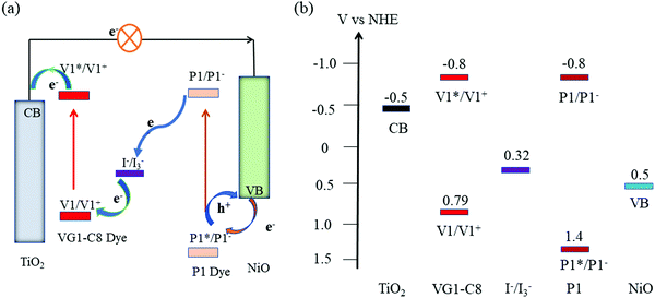
Fig. 1a displays the molecular structures of VG1-C8 and P1 dyes that are used to sensitize the TiO2 and NiO electrodes, respectively. As shown in Fig. 1b, VG1-C8 and P1 show complementary absorption spectra both in solution and on film, which matches the optical requirement of a t-DSSC. Fig. 2 shows the schematic buildup of the t-DSSCs with conventional working principles and corresponding energy levels of all of the components used in the device. The fabrication process of the t-DSSCs in this study can be found in the Experimental section and Scheme S1 in the ESI.† Traditionally, under light illumination, the dye on the photocathode is excited, and the excited dye injects a hole into the valence band (VB) of NiO to form a reduced dye that then reduces I3− of the I−/I3− redox couple. However, according to our previous study,30 NiO surface states or an association species between the surface states and I3− can accept the electrons from the reduced dye. The catalytic behavior of the NiO surface states towards the I−/I3− redox couple could therefore change the working principle of the t-DSSCs from the traditional understanding.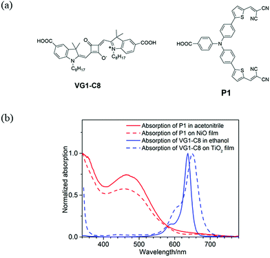 | ||
| Fig. 1 (a) Molecular structures of VG1-C8 and P1 dyes and (b) normalized UV-Vis absorption spectra of VG1-C8 and P1 dyes in solution (extinction coefficient(ε): ε(P1) = 5.8 × 10⁴ M−1 cm−1 in acetonitrile,31ε(VG1-C8) = 3.0 × 10⁵ M−1 cm−1 in ethanol).32 | ||
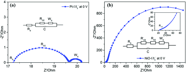
To compare the catalytic performance of Pt and NiO films on reduction of I3−, cyclic voltammetry (CV) was first employed. Fig. 3a shows the CV curve of Pt in 1,2-dimethyl-3-propylimidazolium iodide (DMPII)/I2 (molar ratio: 2/1)-based electrolyte. An obvious reduction peak at a potential of −0.4 V vs. Ag/AgNO3 is observed, and it can be referred to as the reduction of I3− to I−. By replacing Pt with NiO (Fig. 3b), the reduction peak of I3− to I− is shifted to a higher potential, −0.65 V vs. Ag/AgNO3. This suggests that NiO needs more overpotential to catalyze the reaction of I3− to I− than Pt does. The results show that the NiO surface states are very important for catalytic activity. Without the surface states, the NiO film can’t catalyze the reduction of I3−.30 In other words, Pt has a better electrocatalytic activity for I−/I3− redox couple reduction than the NiO film. Secondly, electrochemical impedance spectra (EIS) of the dummy cells (for Pt: Pt/electrolyte/Pt; for NiO: NiO/electrolyte/NiO) were also used to further evaluate the interface charge transfer resistance of Pt and NiO film with electrolytes. As shown in Fig. 4, the interfacial transfer resistance (RCE) of Pt/electrolyte/Pt (Fig. 4a) is much lower than that of NiO/electrolyte/NiO (Fig. 4b), proving that Pt indeed catalyzes the reduction of I3−![[thin space (1/6-em)]](https://www.rsc.org/images/entities/char_2009.gif) 33,34 more efficiently than the NiO film does. Note that the charge transport in or on NiO which is required to reach NiO surface states will certainly create an extra resistance, which adds an overpotential for the overall reduction of I3− to I−, as observed in CV and the large catalytic resistance in EIS. However, this does not necessarily mean that the surface states of NiO have intrinsically worse catalytic performance for I3− reduction when compared with Pt. Actually, as visible in the inset of EIS of NiO/electrolyte/NiO (inset in Fig. 4b), one can observe a small interfacial charge transfer resistance that appears in the high-frequency region, similar to the interfacial charge transfer resistance of the Pt electrode (Fig. 4a) which is only a little bit larger than the Pt resistance. It is probably the real interfacial charge transfer resistance between the NiO surface states and the electrolyte. The large semicircle in the EIS of NiO/electrolyte/NiO then would correspond to the resistance of charge transport in or on the NiO surface and its charge recombination process.
33,34 more efficiently than the NiO film does. Note that the charge transport in or on NiO which is required to reach NiO surface states will certainly create an extra resistance, which adds an overpotential for the overall reduction of I3− to I−, as observed in CV and the large catalytic resistance in EIS. However, this does not necessarily mean that the surface states of NiO have intrinsically worse catalytic performance for I3− reduction when compared with Pt. Actually, as visible in the inset of EIS of NiO/electrolyte/NiO (inset in Fig. 4b), one can observe a small interfacial charge transfer resistance that appears in the high-frequency region, similar to the interfacial charge transfer resistance of the Pt electrode (Fig. 4a) which is only a little bit larger than the Pt resistance. It is probably the real interfacial charge transfer resistance between the NiO surface states and the electrolyte. The large semicircle in the EIS of NiO/electrolyte/NiO then would correspond to the resistance of charge transport in or on the NiO surface and its charge recombination process.
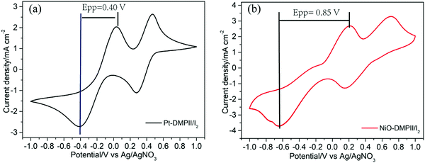 | ||
| Fig. 3 Cyclic voltammetry of (a) a Pt electrode as working electrode and (b) a NiO film as working electrode in DMPII/I2 electrolyte, scan rate: 100 mV s−1. | ||
To assess the effect of the NiO surface states on the photovoltaic performance, n-DSSCs, p-DSSCs, and t-DSSCs were assembled and evaluated. To make the structures of various n- and p-DSSCs devices in this paper easily distinguishable, we put the counter electrode in the brackets of the device name; for example, the device with the name TiO2/VG1-C8 (Pt) means that it is a solar cell with VG1-C8-sensitized TiO2 as the photoanode and Pt as the counter electrode. For the t-DSSCs, the light illumination side is indicated in the bracket of the device name instead. For example, the Tandem device (n) represents that the t-DSSCs are illuminated from the n-type (photoanode) side.
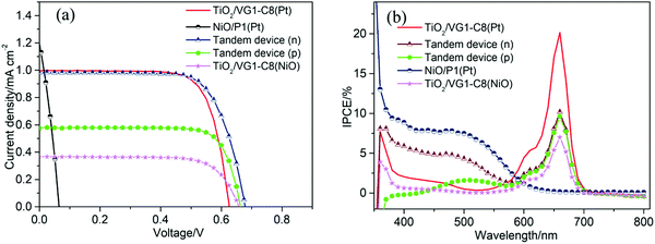
Firstly, to match the photocurrent density of the TiO2 photoanode with that of the NiO photocathode in the tandem device, a thin TiO2 film with thickness of 2 μm was used. Fig. 5a displays the photocurrent density–photovoltage (J–V) curves of all devices, and the corresponding photovoltaic parameters are summarized in Table 1. For the n-DSSC TiO2/VG1-C8 (Pt), a power conversion efficiency (PCE) of 0.466% was achieved with an open-circuit voltage (Voc) of 0.626 V, a short-circuit photocurrent density (Jsc) of 1.00 mA cm−2 and fill factor (FF) of 0.747. However, when the NiO film was employed to replace Pt as the counter electrode, the device TiO2/VG1-C8 (NiO) rendered a PCE of 0.175% with a Voc of 0.657 V, Jsc of 0.38 mA cm−2 and FF of 0.728. Jsc of the TiO2/VG1-C8 (NiO) device is much lower than for the TiO2/VG1-C8 (Pt) device, which could be explained by extra resistance and lower catalytic performance of the NiO film for electrolyte reduction than Pt. This result is consistent with the previously discussed observations in CV and EIS. Notably, the FFs for both devices do not show a significant difference. This could be explained that not all surface states of NiO are involved when the photocurrent flow is low, meaning that the large resistance of the NiO film does not influence the FF. This is different from a device with a much higher photocurrent, which will be discussed in the following section on tandem devices with unmatched Jsc values between the photoanode and photocathode.
| Device | V oc (V) | J sc (mA cm−2) | FF | PCE (%) |
|---|---|---|---|---|
| TiO2/VG1-C8(Pt) | 0.626 | 1.00 | 0.747 | 0.466 |
| TiO2/VG1-C8(NiO) | 0.657 | 0.38 | 0.728 | 0.175 |
| NiO/P1(Pt) | 0.065 | 1.09 | 0.334 | 0.024 |
| Tandem device (n) | 0.677 | 0.98 | 0.723 | 0.480 |
| Tandem device (p) | 0.663 | 0.58 | 0.781 | 0.299 |
For the p-DSSC NiO/P1(Pt), a PCE of 0.024% with a Voc of 0.065 V, Jsc of 1.09 mA cm−2 and FF of 0.334 was obtained. With matching Jsc values between the TiO2/VG1-C8 (Pt) and NiO/P1(Pt) devices, the t-DSSCs showed a PCE of 0.480% with a Voc of 0.677 V, Jsc of 0.98 mA cm−2 and FF of 0.723 when the solar cell was illuminated from the photoanode (Tandem device (n)). Due to the complementary absorption properties of the P1 and VG1-C8 dyes, the Jsc of the t-DSSCs was approximately the same as for the individual n-or p-DSSCs. Under illumination from the photocathode (Tandem device (p)), a PCE of 0.299% with a Voc of 0.663 V, Jsc of 0.58 mA cm−2 and FF of 0.781 was achieved.
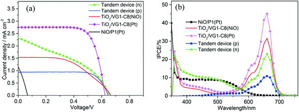
To further probe the effect of the NiO surface states on the tandem DSSCs, a thicker TiO2 film of 4.0 μm was used for the n- or t-DSSCs, and the corresponding J–V curves of the n-, p- and t-DSSCs are shown in Fig. 6a. Their photovoltaic parameters are summarized in Table 2. For the n-DSSC TiO2/VG1-C8(Pt), a PCE of 1.250% with a Voc of 0.624 V, a Jsc of 2.75 mA cm−2 and a FF of 0.729 was achieved. When the NiO film was used to replace the Pt counter electrode, in the TiO2/VG1-C8(NiO) device, it showed a PCE of 0.520% with a Voc of 0.666 V, a Jsc of 1.53 mA cm−2, and a FF of 0.509. Notably, the fill factor of the TiO2/VG1-C8(NiO) solar cell is much lower than for TiO2/VG1-C(Pt). This result differs from the solar cells with a thinner TiO2 film (2 μm) in which the FF values are similar in both solar cells. With increased TiO2 thickness, more electrons are generated at the photoanode and flow to the photocathode. In order to compensate for all the electrons generated by the photoanode at the photocathode, more surface states of NiO film must be accessed and involved in the reduction reaction of I3− to I−. The electron transport in or on NiO film to reach more surface states will create a high resistance, as discussed in the CV and EIS sections, resulting in a low FF for the TiO2/VG1-C8(NiO) device. For the p-DSSC NiO/P1(Pt), a PCE of 0.024% with a Voc of 0.067 V, a Jsc of 1.05 mA cm−2 and a FF of 0.338 was achieved. With a thicker TiO2 film, the photoanode has a much higher Jsc than the photocathode. Therefore, it is interesting to see what happens if they are assembled in a tandem device and more electrons flow from the photoanode into the photocathode. For the t-DSSCs which are illuminated from the photoanode, a PCE of 0.580% with a Voc of 0.656 V, a Jsc of 2.28 mA cm−2, and a FF of 0.388 was reached. This FF value is significantly lower than that of the tandem device with a thin TiO2 film, 0.723 (with a matched photocurrent between the photocathode and the photoanode), which is caused by the need to transport more electrons in or on NiO film to reach the surface states of NiO for I3− reduction as more electrons flow from the photoanode into the photocathode. This result is therefore consistent with the observations for the TiO2/VG1-C8(NiO) device.
| Device | V oc (V) | J sc (mA cm−2) | FF | PCE (%) |
|---|---|---|---|---|
| TiO2/VG1-C8(Pt) | 0.624 | 2.75 | 0.729 | 1.250 |
| TiO2/VG1-C8(NiO) | 0.666 | 1.53 | 0.509 | 0.520 |
| NiO/P1(Pt) | 0.067 | 1.05 | 0.338 | 0.024 |
| Tandem device (n) | 0.656 | 2.28 | 0.388 | 0.580 |
| Tandem device (p) | 0.647 | 0.94 | 0.758 | 0.461 |
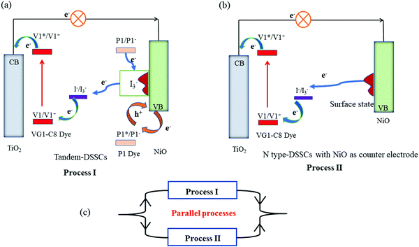
Based on the photovoltaic data, we can now conclude the roles of surface states of NiO film in t-DSSCs. As elucidated in Fig. 7, when the Jsc values of the photoanode and photocathode are matched, all or the majority of electrons from the photoanode can be supported by the injected holes in NiO from excited P1 dye (Process I). Then, the reduced P1 dyes give electrons to NiO surface states which are used for the reduction of I3−. As the injected holes in NiO are taken away by external electrons (e.g.: a bias potential), the charge recombination between electrons in the surface state and injected holes in NiO is significantly inhibited. Generally, the serious charge recombination in p-DSSCs is responsible for its low FF.35 Therefore, for the tandem solar cells with matched photocurrent from both photoelectrodes, the FF of the device is improved as compared to that of the individual p-DSSCs.
However, when the Jsc of the photoanode is much larger than that of the photocathode, the holes in NiO VB are not sufficient to accommodate all the electrons coming from the photoanode and the NiO surface states start playing a role. In addition to process I, the extra electrons need to move in or on the NiO film to reach the NiO surface states and then reduce the redox couple (Process II) which therefore creates a larger transport and interface resistance. The consequence is a lower FF for the tandem DSSCs with an unmatched Jsc from both photoelectrodes. According to the traditional understanding of the t-DSSCs in series, the Jsc of the tandem DSSCs should be equal to or lower than that of the photocathode and the photoanode. However, due to the role of NiO surface states, the Jsc of t-DSSCs with an unmatched photocurrent from both photoelectrodes is actually in the range of the Jsc of the individual p- and n-DSSCs, but much closer to that of the photoanode. As shown in Fig. 7, when the Jsc of the photoanode is much higher when compared with the photocathode in a tandem DSSC, the t-DSSCs should have two parallel charge transport processes involved: one is with NiO/P1 as a dark counter electrode, as in n-DSSCs (TiO2/VG1-C8(NiO)), and the other is with NiO/P1 as a photoelectrode, as in an ideal t-DSSC. Dai and co-authors36 reported a diode model to predict the J–V curve of the tandem DSSCs. In their results, the Voc of tandem DSSCs is the sum of n-type and p-type. The current density of tandem DSSCs is determined by the photoanode, which is almost equal to the n-type device. However, in our case, the photocurrent density of tandem DSSCs is actually in the range of the Jsc of the individual p- and n-DSSCs, but much closer to that of the photoanode, when the photocurrent densities of the photoanode and photocathode are mismatched. The mentioned diode model seems only to fit well for the matched photocurrent density between the photoanode and photocathode. The proposed working principles of the tandem DSSCs in this work can also explain the phenomenon beyond the case that the photocurrent matches between two photoelectrodes.
Mysteries of IPCE spectra of tandem DSCs
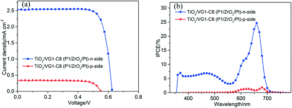
From the IPCE spectral response of individual n- and p-DSSCs (Fig. 5b and 6b), it is obvious that the P1 and VG1-C8 dyes have well-matched photoresponse spectra, with little overlap. According to the basic working principle of an ideal t-DSSC, one should not expect to see an IPCE response from either VG1-C8 or P1 dye, except for the overlapping absorption region between these two dyes where both dyes can be excited and generate electron flow in t-DSSCs. However, we did see this unexpected IPCE response from both VG1-C8 and P1 dyes in the tandem device. Similar to our observations, other groups have also found IPCE responses from both dyes in the t-DSSCs.37–39 As discussed above, since the NiO surface states can catalyze the I3− reduction, the photo-response from VG1-C8 dyes in IPCE of the t-DSSCs can be reasonably explained by the NiO film working as a counter electrode. However, the photo-response of P1 (400–600 nm) in the IPCE spectra for t-DSSCs is mysterious, as TiO2 cannot act as a counter electrode to catalyze the I−/I3− electrolyte in a p-type DSSC,28 which is evident from a solar cell NiO/P1(TiO2) that did not show any P1 spectral response in the IPCE spectrum (Fig. S2, ESI†).Using a P1-sensitized ZrO2 film (P1/ZrO2) instead of the P1/NiO film in the t-DSSCs, with Pt on the FTO surface to catalyze I3− reduction, the spectral response of P1 in the IPCE spectra of such t-DSSCs was still remaining (Fig. 8). This led us to consider electron and energy transfer between P1 and VG1-C8 dyes as a possible explanation. The distance between P1 on the photocathode and VG1-C8 on the photoanode is about 25 μm, which should preclude electron transfer and energy transfer directly between the dyes on the two photoelectrodes. However, if the P1 dye desorbs from the NiO surface, it could diffuse to come in close proximity to the photoanode, which makes the electron and energy transfer possible. To check if the P1 dye desorbs from the photocathode in the presence of a solvent, a NiO/P1 film was immersed into acetonitrile/tert-butyl pyridine (same ratio as in the electrolyte) for 1 h to check its absorbance (Fig. S3, ESI†). The data show that the absorbance of the NiO/P1 film decreases from 0.4 to 0.2 at 480 nm. The result indicates that the P1 dye can indeed detach from NiO film in the presence of electrolyte solvent and come in contact with, and even attach to, the TiO2 film. Electron transfer from the ground state VG1-C8 to excited P1 is thermodynamically favorable (Fig. 2b) and could be followed by electron injection from reduced P1 to TiO2. Alternatively, the emission of P1 has a good overlap with the absorption of VG1-C8, so the process of energy transfer between desorbed P1 and VG1-C8 is clearly possible.
To verify that energy transfer between two dyes is possible, the fluorescence of a certain concentration of VG1-C8 acetonitrile solution was recorded in the presence of various amounts of P1 dye. As shown in Fig. 9a, an increasing addition of P1 dye into the VG1-C8 solution (Fig. 9a) leads to the quenching of the intensity of P1 dye at 650 nm. In contrast, the PL intensity of VG1-C8 dye at 680 nm was increased, which suggests its sensitization by energy transfer from P1*. In order to observe the energy transfer between two dyes on a film, the absorption spectrum and excitation spectrum monitoring the emission at 680 nm (Fig. 9b) of ZrO2/VG1-C8/P1 film were measured. These two spectra gave similar shapes, with a strong contribution from the absorption bands of both dyes to the VG1-C8 fluorescence. Moreover, the emission spectrum of the ZrO2/VG1-C8/P1 film (Fig. S4, ESI†) shows that the emission peak of the P1 dye is largely quenched. These results prove that there is indeed energy transfer from P1 to VG1-C8 dye both in solution and on film. Although the absorption of I3− extends to 500 nm, one can see that there is no IPCE response at 500 nm at all in the absence of the dye from the previous report.40 If we considered that the IPCE response of the device without dye is from the electrolyte, then the spectral overlap between the emission of P1 and absorption I3− should not be possible. Kim and co-workers37 used a cobalt-based redox couple in tandem DSSCs with P1 and SQ dyes. The IPCE response from both dyes can still be observed in the tandem DSSC. Then, we can exclude the Förster resonance energy transfer (FRET) between P1 and I3−. Based on the spectral overlap of the two dyes, the energy transfer between the two dyes should be from FRET.41,42
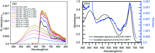 | ||
| Fig. 9 (a) The PL spectra of P1 and VG1-C8 dye in acetonitrile (excitation at 480 nm). (b) The absorption and fluorescence excitation spectra (emission at 680 nm) of ZrO2/VG1-C8/P1. | ||
To further make sure that the observed IPCE response from both dyes in t-DSSCs is indeed due to the FRET between the two dyes, a TiO2 film was first dipped into the VG1-C8 solution for 12 h and then sensitized with P1 dye solution for 6 h. A TiO2/VG1-C8/P1 (Pt) cell was fabricated (Table S4, ESI†). For such a cell, the IPCE spectrum in Fig. 10b shows a high IPCE value for the P1 dye. However, when a bare TiO2 film was sensitized with the P1 dye (TiO2/P1), the IPCE value P1 was much lower than that of the TiO2/VG1-C8/P1 (Pt) device, probably due to poor electron injection from the excited P1 to TiO2. This result indicates that there is indeed FRET happening between P1 and VG1-C8. When the P1 dye (1 mg mL−1) is introduced into the electrolyte of the TiO2/VG1-C8 solar cell, the IPCE response of P1 is also observed. It can therefore be concluded that the spectral response of the P1 dye in the IPCE spectra of tandem solar cells is highly possible from FRET between the desorbed P1 dye and the VG1-C8 dye on the electrode, with the NiO film and its surface states working as a counter electrode. This result also explains why the P1 IPCE response in a tandem solar cell is weaker with illumination from the p-side than from the n-side (Fig. 5), since the remaining P1 dyes on the photocathode filter the light. Although these experiments still do not completely exclude another pathway: electron transfer from VG1-C8 to excited P1, followed by electron injection from P1-, the experimental results do suggest inefficient injection from P1* which gives time for FRET to happen. This implies that the FRET reaction is more plausible, because (1) FRET happens efficiently in dilute solution and on ZrO2 film; (2) FRET is more long-range than electron transfer and may therefore happen faster than electron transfer between co-adsorbed dyes. However, it would not be surprising if a small portion of excited P1 dyes get electrons from VG1-C8 and then inject electrons to the TiO2 CB.
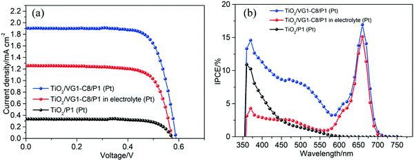 | ||
| Fig. 10 (a) J–V curves of TiO2 film sensitized VG1-C8 or P1 dye. (b) IPCE spectra of TiO2 film sensitized VG1-C8 or P1 dye. | ||
Conclusion
In summary, the roles of NiO surface states in tandem dye-sensitized solar cells (t-DSSCs) have been assessed. The NiO surface states affect the charge transport processes in the tandem DSSCs and also participate in the IPCE response from both dyes on different photoelectrodes. By adjusting the photocurrent density of the TiO2 photoanode in combination with the information from our previous work on NiO surface states, we can conclude that there are two pathways for electron transport through the NiO photocathode: (I) the electrons generated from the photoanode are compensated at the photocathode by the injected holes from excited dyes into NiO and (II) electrons generated at the photoanode go through the NiO film and directly reduce the redox couple (I−/I3−), particularly when comparatively more electrons are generated at the photoanode than holes are being generated at the photocathode. Having a matching photocurrent from both photoelectrodes, meaning that an equal number of electrons and holes are generated at their respective electrodes, the sole presence of process I can render a high fill factor for t-DSSCs. If process II is involved to a large degree, the process will lower the FF factor of t-DSSCs due to unwanted resistance caused by the electron transport in or on the NiO film. Furthermore, due to the catalytic behavior of NiO surface states towards the electrolyte and the confirmed energy transfer between desorbed P1 and VG1-C8 dye on TiO2, one can therefore explain the observed unexpected IPCE response from both dyes in a tandem device, despite their complementary optical absorption with little spectral overlap. This study provides new understandings to explain the strange IPCE phenomenon which has been existing in the research community for a long time.Conflicts of interest
The authors declare no competing financial interest.Acknowledgements
We gratefully thank the Carl-Trygger Foundation (CT 19:370) and the Swedish Energy Agency (49278-1) for the financial support. We also would like to thank Dr Lei Tian for helpful discussions.References
- B. O'Regan and M. Grätzel, Nature, 1991, 353, 737–740 CrossRef.
- A. Hagfeldt, G. Boschloo, L. Sun, L. Kloo and H. Pettersson, Chem. Rev., 2010, 110, 6595–6663 CrossRef CAS PubMed.
- L. Zhang, X. Yang, W. Wang, G. G. Gurzadyan, J. Li, X. Li, J. An, Z. Yu, H. Wang, B. Cai, A. Hagfeldt and L. Sun, ACS Energy Lett., 2019, 4, 943–951 CrossRef CAS.
- E. Benazzi, J. Mallows, G. H. Summers, F. A. Black and E. A. Gibson, J. Mater. Chem. C, 2019, 7, 10409–10445 RSC.
- H. Tian, Sustainable Energy Fuels, 2019, 3, 888–898 RSC.
- S. Sumikura, S. Mori, S. Shimizu, H. Usami and E. Suzuki, J. Photochem. Photobiol., A, 2008, 199, 1–7 CrossRef CAS.
- F. Odobel, L. Le Pleux, Y. Pellegrin and E. Blart, Acc. Chem. Res., 2010, 43, 1063–1071 CrossRef CAS PubMed.
- B. Xu, L. Tian, A. S. Etman, J. Sun and H. Tian, Nano Energy, 2019, 55, 59–64 CrossRef CAS.
- D. Xiong and W. Chen, Front. Optoelectron., 2012, 5, 371–389 CrossRef.
- A. Nattestad, I. Perera and L. Spiccia, J. Photochem. Photobiol., C, 2016, 28, 44–71 CrossRef CAS.
- M. S. Prévot and K. Sivula, J. Phys. Chem. C, 2013, 117, 17879–17893 CrossRef.
- F. Li, K. Fan, B. Xu, E. Gabrielsson, Q. Daniel, L. Li and L. Sun, J. Am. Chem. Soc., 2015, 137, 9153–9159 CrossRef CAS PubMed.
- J. He, H. Lindström, A. Hagfeldt and S.-E. Lindquist, J. Phys. Chem. B, 1999, 103, 8940–8943 CrossRef CAS.
- J. He, H. Lindström, A. Hagfeldt and S.-E. Lindquist, Sol. Energy Mater. Sol. Cells, 2000, 62, 265–273 CrossRef CAS.
- M. Yu, G. Natu, Z. Ji and Y. Wu, J. Phys. Chem. Lett., 2012, 3, 1074–1078 CrossRef CAS PubMed.
- M. Yu, T. I. Draskovic and Y. Wu, Phys. Chem. Chem. Phys., 2014, 16, 5026–5033 RSC.
- O. Langmar, E. Fazio, P. Schol, G. de la Torre, R. D. Costa, T. Torres and D. M. Guldi, Angew. Chem., Int. Ed., 2019, 58, 4056–4060 CrossRef CAS.
- J. Qian, K.-J. Jiang, J.-H. Huang, Q.-S. Liu, L.-M. Yang and Y. Song, Angew. Chem., Int. Ed., 2012, 51, 10351–10354 CrossRef CAS PubMed.
- Y. Hu, Z. Zheng, H. Jia, Y. Tang and L. Zhang, J. Phys. Chem. C, 2008, 112, 13037–13042 CrossRef CAS.
- S. Wrede and H. Tian, Phys. Chem. Chem. Phys., 2020, 22, 13850–13861 RSC.
- C. J. Wood, G. H. Summers and E. A. Gibson, Chem. Commun., 2015, 51, 3915–3918 RSC.
- A. Nattestad, A. J. Mozer, M. K. R. Fischer, Y. B. Cheng, A. Mishra, P. Bäuerle and U. Bach, Nat. Mater., 2010, 9, 31–35 CrossRef CAS PubMed.
- L. D’Amario, L. J. Antila, B. Pettersson Rimgard, G. Boschloo and L. Hammarström, J. Phys. Chem. Lett., 2015, 6, 779–783 CrossRef.
- L. D’Amario, R. Jiang, U. B. Cappel, E. A. Gibson, G. Boschloo, H. Rensmo, L. Sun, L. Hammarström and H. Tian, ACS Appl. Mater. Interfaces, 2017, 9, 33470–33477 CrossRef.
- L. D’Amario, G. Boschloo, A. Hagfeldt and L. Hammarström, J. Phys. Chem. C, 2014, 118, 19556–19564 CrossRef.
- L. D'Amario, J. Föhlinger, G. Boschloo and L. Hammarström, Chem. Sci., 2018, 9, 223–230 RSC.
- N. T. Z. Potts, T. Sloboda, M. Wächtler, R. A. Wahyuono, V. D’Annibale, B. Dietzek, U. B. Cappel and E. A. Gibson, J. Chem. Phys., 2020, 153, 184704 CrossRef CAS PubMed.
- C. J. Wood, C. A. McGregor and E. A. Gibson, ChemElectroChem, 2016, 3, 1827–1836 CrossRef CAS.
- M. Bonomo, D. Dini and A. G. Marrani, Langmuir, 2016, 32, 11540–11550 CrossRef CAS PubMed.
- L. Tian, R. Tyburski, C. Wen, R. Sun, M. Abdellah, J. Huang, L. D’Amario, G. Boschloo, L. Hammarström and H. Tian, J. Am. Chem. Soc., 2020, 142, 18668–18678 CrossRef CAS PubMed.
- J. Park, C. Barolo, F. Sauvage, N. Barbero, C. Benzi, P. Quagliotto, S. Coluccia, D. Di Censo, M. Grätzel, M. K. Nazeeruddin and G. Viscardi, Chem. Commun., 2012, 48, 2782–2784 RSC.
- P. Qin, H. Zhu, T. Edvinsson, G. Boschloo, A. Hagfeldt and L. Sun, J. Am. Chem. Soc., 2008, 130, 8570–8571 CrossRef CAS PubMed.
- F. Gong, H. Wang, X. Xu, G. Zhou and Z.-S. Wang, J. Am. Chem. Soc., 2012, 134, 10953–10958 CrossRef CAS PubMed.
- Z. Jin, M. Zhang, M. Wang, C. Feng and Z.-S. Wang, Acc. Chem. Res., 2017, 50, 895–904 CrossRef CAS PubMed.
- Z. Huang, G. Natu, Z. Ji, M. He, M. Yu and Y. Wu, J. Phys. Chem. C, 2012, 116, 26239–26246 CrossRef CAS.
- J. Wei, Z. Shao, B. Pan, S. Chen, L. Hu and S. Dai, Materials, 2020, 13, 2936 CrossRef CAS PubMed.
- P. Ho, S. Thogiti, L. Q. Bao, R. Cheruku, K.-S. Ahn and J. Hong Kim, Solar Energy, 2018, 161, 9–16 CrossRef CAS.
- P. Ho, S. Thogiti, Y. H. Lee and J. H. Kim, Sci. Rep., 2017, 7, 2272 CrossRef PubMed.
- Y. H. Lee, J. Y. Park, S. Thogiti, R. Cheruku and J. H. Kim, Electron. Mater. Lett., 2016, 12, 524–529 CrossRef CAS.
- H. Zhu, A. Hagfeldt and G. Boschloo, J. Phys. Chem. C, 2007, 111, 17455–17458 CrossRef CAS.
- J. I. Basham, G. K. Mor and C. A. Grimes, ACS Nano, 2010, 4, 1253–1258 CrossRef CAS PubMed.
- G. K. Mor, J. Basham, M. Paulose, S. Kim, O. K. Varghese, A. Vaish, S. Yoriya and C. A. Grimes, Nano Lett., 2010, 10, 2387–2394 CrossRef CAS PubMed.
Footnote |
| † Electronic supplementary information (ESI) available. See DOI: https://doi.org/10.1039/d2ya00035k |
| This journal is © The Royal Society of Chemistry 2022 |

