
 Open Access Article
 This Open Access Article is licensed under a Creative Commons Attribution-Non Commercial 3.0 Unported Licence
High colouring efficiency, optical density and inserted charge in sol–gel derived electrochromic titania nanostructures
Robert C.
Pullar
 *ab,
Roberto
Giannuzzi
*cd,
Tania
Prontera
c,
David M.
Tobaldi
bc,
Marco
Pugliese
c,
Luisa
De Marco
c,
Pierluigi
Cossari
c,
Giuseppe
Gigli
ce and
Vincenzo
Maiorano
c
*ab,
Roberto
Giannuzzi
*cd,
Tania
Prontera
c,
David M.
Tobaldi
bc,
Marco
Pugliese
c,
Luisa
De Marco
c,
Pierluigi
Cossari
c,
Giuseppe
Gigli
ce and
Vincenzo
Maiorano
c
aDepartment of Molecular Sciences and Nanosystems (DSMN), Ca’ Foscari University of Venice, Scientific Campus, Via Torino 155, 30172 Venezia Mestre, VE, Italy. E-mail: robertcarlyle.pullar@unive.it
bDepartment of Engineering of Materials and Ceramics/CICECO-Aveiro Institute of Materials, University of Aveiro, Campus Universitário de Santiago, 3810-193 Aveiro, Portugal
cCNR-NANOTEC – Istituto di Nanotecnologia, Strada Provinciale Monteroni, Lecce, Campus Ecotekne, 73100 Lecce, Italy. E-mail: roberto.giannuzzi@nanotec.cnr.it
dDepartment of Mathematics and Physics, University of Salento, Via Monteroni, 73100, Lecce, Italy
eDipartimento di Matematica e Fisica E. de Giorgi, Università Del Salento, Campus Ecotekne, via Monteroni, Lecce, 73100, Italy
First published on 11th April 2022
Abstract
A pure TiO2 thin film (100–120 nm) was made from a green aqueous sol–gel precursor on FTO glass and calcined at 430 °C. It was a mix of amorphous, anatase, rutile and brookite TiO2 phases, and exhibited very good electrochromic properties over visible and NIR wavelengths with an applied bias of +0.1 V to −1.5 V. It was highly transparent showing excellent coloration with applied voltage, with transmittance modulation (ΔT) = 69.7% at 550 nm, 86% at 700 nm and an overall ΔT between 400–1650 nm of 60%, giving a very large change in optical density (ΔOD) of 1.4 at 550 nm and 2.4 at 700 nm. Cyclic voltammograms had typical peaks for TiO2 at −1.3 V for colouration and −0.9 V for bleaching, with a high separation of 0.37 V between peaks, and a charge density after charging for 25 min of Qc = 50 mC cm−2. After only 60 s and 120 s at −1.5 V, inserted charge values of 17.6 and 22 mC cm−2 were observed, leading to a high colouration efficiency (CE) of 55.9 cm2 C−1 at 550 nm. These ΔOD, ΔT, Qc and CE values are superior to any previously reported for crystalline sol–gel TiO2 films. They also possessed rapid switching times for bleaching and colouring of τb90% = 10 s and τc90% = 55 s, comparable to the best previously reported sol–gel anatase-based TiO2 films. This makes this nanomaterial an excellent candidate for smart windows and other electrochromic devices and applications.
1. Introduction
Chromism is a change in colour depending on the change of electron states in the molecule or crystal, especially the π electrons and d electrons, the most common forms being thermochromic, photochromic and electrochromic materials. Once a stimulus (heat, light, electrical field) changes the electron states of a material, chromism will occur. Electrochromic materials manifest reversible and visible change in optical properties as the result of electrochemical oxidation or reduction at different electrical potentials. When a voltage is applied to such materials, their optical properties such as transmittance and reflectance can be reversibly modulated, causing a reversible darkening.1In 1953, Kraus first described the electrochromism of tungsten oxide in an unpublished laboratory report at Balzers AG in Liechtenstein, describing electrically induced colour changes in thin films of tungsten oxide immersed in sulphuric acid.2,3 However, electrochromism was brought to public attention after Deb's publications on amorphous and crystalline tungsten oxide films and the first WO3-based electrochromic devices between 1969–1973.4,5 Since then, studies of electrochromism have gained great attention owing to their extensive potential applications, e.g. architecture and smart windows to save energy, variable rear-view mirrors, sun-roofs and spectacles/eyewear, e-papers and electrochromic displays (which are non-emissive, similar to LCD liquid crystal displays), dye sensitised solar cells for photovoltaics, energy storage materials such as Li-ion batteries, as well as thermal control of spacecraft and military camouflage/shielding against thermal sensors in the infrared between 3–14 μm.6–17
Electrochromic properties can be found in almost all the transition-metal oxides and their properties have been investigated extensively.2 During recent decades, numerous studies have reported electrochromic materials, including metal oxides, organic molecules and conducting polymers. As result, many electrochromic materials have been developed, such as WO3,18 TiO2,19 NiO,20 supramolecular metallo-polymers,21 polyaniline,22 polythiophene23 and other polymers.24
As a suitable electrochromic material, TiO2 shows great potential in electrochromic research. TiO2 based films can possess a great degree of transparency to visible light, large specific surface area, large dielectric constant and capable charge transport properties. One common characteristic of electrochromic oxide materials is that they are wide-band gap semiconductors with a structure that allows easy electrical field induced proton (H+) or Li+ ion intercalation or insertion. TiO2 is such a material.25 In the case of TiO2, the insertion process is accompanied by a reduction process: TiO2 + xY+ + xe− → YxTiO2 (in which Y+ is the charged ion (e.g. H+ or Li+) and e− is an electron released from the reduction of Ti4+ → Ti3+). Some of the Ti4+ is reduced to Ti3+ to compensate for the cation, and this leads to a colour change of the material (cathodic colouration), typically darkening, as there is a change of visible light absorption, ascribed to the electronic band gap changing from the UV (Eg = 3.0–3.2 eV) to the visible (Eg = 2.2–2.5 eV) range.26 This is due to the formation of a polaronic state, widening the band gap as the conduction band gains electrons.27–29 Being a semiconducting material, TiO2 is also suitable for photocatalytic applications under sunlight, and this combination of photocatalysis and electrochromism makes titania thin films promising candidates for self-cleaning smart window applications.30 Other related applications of transparent electrochromic titania in particular are in hydrogen sensing, water photolysis and photoelectrochemical devices.11
To fabricate a device that is transparent in the unbiased state, the active oxide layer is usually put on a conductive glass, and another conductive electrode is mounted on top. The space between the electrodes is filled with an electrolyte that contains the ions to be inserted.11 The conductor must be transparent, combining excellent electrical conductivity and very low optical absorption, but many oxide conductors such as indium tin oxide (∼10% Sn-doped In2O3, ITO) often require a heated substrate for optimum properties. For this reason, fluorine-doped tin oxide (FTO) is often preferred. A typical electrolyte in such devices is LiClO4 in propylene carbonate, enabling the insertion of Li+ ions into the TiO2. The nanoporosity of the electrochromic and counter-electrode films must also be well-controlled, and the electrolyte should not allow leakage currents between the electrochromic and counter-electrode layers. Ideally, devices should also have long-term durability with voltage and current changes during colouring/bleaching.12
Sol–gel was the first process investigated to make thin films of amorphous or crystalline nanoparticles (NPs) of electrochromic TiO2, exhibiting a large optical transmission variation in the UV, visible or infrared range and acceptable kinetics under H+ or Li+ insertion.31 The first reports were in 1989–1992,32,33 in which the electrochromic properties of the coatings were rather poor, with a grey colour. Superior electrochromic TiO2 NP thick films (3.5–4 μm thick) were reported in 1994, made by spreading a paste of 15 nm colloidal TiO2 NPs on conducting glass, which after autoclaving at 200 °C and firing at 450 °C/30 in in air formed crystalline and highly porous anatase.34 This showed reversible Li intercalation accompanied by an intense colour change from transparent to dark blue, which contrasted with anatase films prepared by conventional methods which were unable to intercalate Li ions to any significant extent. In 1999 spin-coated sol–gel TiO2 thin films (80–150 nm) were used to produce amorphous and anatase TiO2 films on ITO-coated glass, and the charge capacity and coloration efficiency of the amorphous film was found to be greater than that of the anatase film, a trend which has often been observed, and attributed to the greater porosity of the amorphous TiO2 facilitating Li+ intercalation. However, the electrochromic processes were quite slow, taking tens of seconds to colour or bleach.35 Nanocrystalline-TiO2 anatase thin films on ITO prepared by a sol–gel dipping method and annealed at 480 °C/3 h reported in 2003 exhibited a good reversible coloration and bleaching process,36 but the full coloration response time (typically the time passed until the colouration or bleaching reaches 90% of its maximum) was still found to be large at around 45 min. Another study in 2009 demonstrated that amorphous TiO2 sol–gel derived films annealed at 300 °C, which still contained some OH groups, on Sb-doped SnO2 coated glass, had a poor initial transmittance and showed only moderate colouration, which was even worse for anatase films.37
More recent results on sol–gel TiO2 films still show rather poor results, such as 200–300 nm spin coated anatase films (6 deposited layers, with heating to 250 °C between each coating) which had an initial transmittance of ∼80% in the visible and NIR region that reduced to ∼50% when coloured,30 and amorphous TiO2 films switching between ∼80% transmittance when bleached and 60% transmittance when coloured.38 No switching times were given for either of these materials. Clearly, purely sol–gel derived TiO2 electrochromic materials still need a lot of development and optimisation. In an attempt to improve sol–gel films, amorphous and anatase sol–gel derived TiO2 films (600–332 nm thick) were aged with diethanolamine as a stabilising agent for one week prior to gelation and coating, exhibiting an enhanced diffusion coefficient, ion storage capacity and optical modulation in comparison to films prepared from a freshly prepared sol. The 332 nm thick porous anatase films produced at 400 °C were the best, but still had slow colouration times of several minutes.39
In this paper we report the electrochromic properties of a thin film of TiO2 nanoparticles (NPs) produced via a simple, green, aqueous sol–gel process. This was spin-coated on FTO-glass and heated to 430 °C for 30 min to produce a transparent 100–120 nm thick electrochromic film, which exhibited very good rapid and reversible colouration demonstrated by vis-NIR spectrometry, cyclic voltammetry and chronoamperometric curves. It is superior to any previously reported sol–gel derived electrochromic titania films.
2. Results and discussion
The pure titania sol and NPs have been fully characterised and their physical and crystallographic properties discussed previously.40,41 To summarise, when calcined at 450 °C/2 h the pure TiO2 NPs consisted of 25.1 wt% anatase, 37.7 wt% rutile, 10.3 wt% brookite and 26.9 wt% amorphous phases. All of these have been shown to be useful electrochromic phases, with brookite,42 rutile43 and porous amorphous35,37,38 phases all being shown to have some advantages over anatase, and rutile nanowires decorated with anatase NPs having enhanced optical contrast, coloration efficiency and transient current density.44 Hence, a material with a combination of all of these phases has great potential. The calculated crystallite sizes of these phases in our pure TiO2 NPs were 9.9 nm for anatase, 14.1 nm for rutile and 3.2 nm for brookite,45 although the actual particle size ranged from 10 nm up to 50 nm, and they were heavily clustered.40 There was no significant change in the crystal phases of the titania produced with PAA compared to that without.When spin coated onto the FTO-glass substrates, the TiO2 films produced were opaque due to agglomeration of the NPs, and hence not suitable for electrochromic devices. Therefore, 5 wt% of PAA surfactant was added to the sols and the films produced as before. The PAA prevented agglomeration during coating, but was then burnt out during annealing at 430 °C, leaving a very even, transparent TiO2 film, probably with increased porosity due to the loss of the PAA. The as-prepared transparent film after annealing at 430 °C/30 min is shown in Fig. 1e.
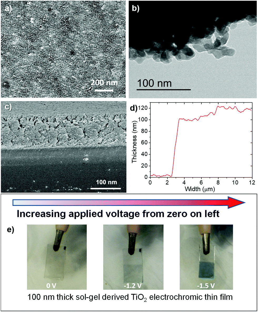 | ||
| Fig. 1 (a) SEM image of the sol–gel derived TiO2 thin film, as prepared and annealed at 430 °C/30 min. (b) TEM image of scratched portions of the sol–gel derived TiO2 thin film. (c) SEM image showing cross-section of the film. (d) Depth profile of the film, 100–120 nm thick. (e) Photographs of initial transparency, and increasing colouration with increasing applied voltage, of the sol–gel TiO2 electrochromic thin film (these are not the samples used for electrochromic measurements). | ||
SEM images of the as-produced film after annealing at 430 °C/30 min are shown in Fig. 1a. The TiO2 film presented a smooth surface, with a few larger fissures tens of microns in length from the drying process, but as expected, any nanoparticles and mesopores were below the resolution of the SEM instrument (i.e., <30 nm). This was confirmed by TEM analysis carried on the scratched flakes of the film (Fig. 1b), showing that the thin film is made of NPs sized about around 10 nm, partially fused to each other at the edges. The cross-section of the annealed film is shown in Fig. 1c, and the depth profile demonstrating that the thickness is 100–120 nm is shown in Fig. 1d. The high transparency and homogeneity of as-produced thin films can be observed in Fig. 1e.
As also seen in Fig. 1e, the TiO2 film exhibited strong electrochromic properties when subjected to a voltage, possessing a high degree of colouration and darkening under an applied voltage, becoming completely opaque as the voltage increased.
2.1 Visible-NIR spectra, transmittance, optical contrast (ΔT) and optical density (ΔOD)
The transmittance spectra were measured in situ with a three-electrode set-up, by applying a bias of +0.1 V and −1.5 V for 120 s. The visible-near IR (vis-NIR) spectra of the film between 320–1650 nm in the coloured and bleached states are shown in Fig. 2a. The TiO2 film showed a high degree of transparency with 86–95% transmittance across the entire 400–1650 nm range. As an increasing voltage was applied, the film became progressively darker, and Fig. 2a shows the reduction in transmittance with an application of −1.5 V. A transmittance of below 27% was observed in the entire visible region, falling to as low at 8% at around 700 nm where the greatest coloration occurred. In the NIR region between 800–1650 nm a transmittance of between 9% to 60% was observed, the value increasing with greater wavelengths. To the eye, the electrode appeared black in the coloured state with an applied bias of −1.5 V, able to effectively shield the visible radiation and a significant portion of the initial NIR region. A bias of only +0.1 V was sufficient to bleach the film back to the fully transparent state.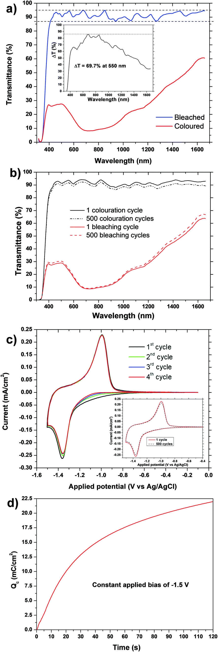 | ||
| Fig. 2 (a) Vis-NIR transmittance spectra of the sol–gel TiO2 based electrode (thickness = 100–120 nm) in bleached state (blue curve, +0.1 V) and coloured state (red curve, −1.5 V). Dashed lines indicate the transmittance range in the bleached state (86–95%). Inset shows the transmittance modulation (ΔT, optical contrast). (b) Change in transmittance of coloured and bleached states after 500 cycles. (c) Cyclic voltammogramms recorded at a scan rate of 1 mV s−1 between +0.1 and −1.5 V, for 4 cycles. Inset shows change after 500 cycles. (d) Inserted charge vs. time with a constant applied bias of −1.5 V. | ||
The optical contrast of an electrochromic material is given by its transmittance modulation (ΔT):
| ΔT = Tb − Tc | (1) |
Another measure of the colour change between bleached and coloured states is the change in optical density (ΔOD), which is given by:
| ΔOD = ln(Tb/Tc) | (2) |
The ΔOD at 550 nm was 1.4, and at 700 nm it was 2.4, both with an applied bias of −1.5 V for 120 s.
Many reports on transmittance, ΔT and ΔOD of TiO2 electrochromics are very selective in the wavelengths they choose to analyse, reporting those with the optimum values, and giving no details over a wide range of wavelengths. Most reported sol–gel anatase TiO2 films have rather poor transmittance modulation with ΔT ∼20–30%, even at the optimum selected wavelengths,30,35,37–39 without the addition of additives such as chromophores or other ions. For example: 80–150 nm thick films had ΔT at 630 nm of 18% and 10% when annealed at 150 °C and 400 °C, respectively;35 films annealed at 300 °C had ΔT = 27%, 20% and 10% at wavelengths of 750, 600 and 550 nm, respectively;37 films annealed at 250 and 400 °C had ΔT values between 550–750 nm of 20% and 10%, respectively;38 a 200 nm thick film annealed at 400 °C had ΔT = 50% at 550 nm;39 a 230 nm thick film had ΔT up to ∼52% at 550 nm when bias was applied for 45 min.36 Aged TiO2 sol–gel films (332 nm thick) proved to be a bit better, with peak transmittance of 80% at 550 nm, 65–80% over the 400–800 nm range, and ΔT of up to 50% at 550 nm.39
Our films have ΔT values superior to all previously reported sol–gel films, despite their small thickness of only 100–120 nm, which creates an initial high transparency in the bleached state, but makes their subsequent high degree of colouration even more impressive. In particular, our TiO2 films exhibit high ΔT values of ≥60% over the range of 400–1200 nm. This may be at least partly due to the fact that they consist of a combination of anatase, rutile, brookite and amorphous phases of TiO2, which have all been shown above to have individual advantages and contributions to the electrochromic process (for example, brookite nanoneedle films had a reported ΔOD = 0.85 at 600 nm, although this value was obtained using a log, and not ln, conversion42).
Early sol–gel films were reported with low ΔOD values of 0.18 for amorphous and 0.12 for anatase TiO2.31,35 A 280 nm sol–gel anatase film had a reported ΔOD of 0.55 at 550 nm, with a stated ΔT of 30%,30 and the best ΔOD values previously reported for sol–gel TiO2 films were 1.7 at 550 nm and 1.57 at 700 nm.36 Our ΔOD value of 1.4 at 550 nm is comparable to this, and the maximum ΔOD of 2.4 at 700 nm is greatly superior. Our films are compared to all previously published sol–gel titania films, as well as some of the best titania films produced by other methods, in Table 1.
| Ref. | Year | Thin film preparation technique | Film thickness (nm) | T b (%) | T c (%) | ΔT (%) | ΔOD (ln![[thin space (1/6-em)]](https://www.rsc.org/images/entities/char_2009.gif) Tb/Tc) Tb/Tc) |
Q C (mC cm−2) | CE (cm2 C−1) | τ c (s) | τ b (s) |
|---|---|---|---|---|---|---|---|---|---|---|---|
| 35 | 1999 | Sol–gel | 80 (heated to 150 °C) | 90 at 630 nm | 72 at 630 nm | 18 at 630 nm | 0.18 at 630 nm | 14.8 | 9.93 at 630 nm | — | — |
| 13.95 at 850 nm | |||||||||||
| 150 (heated to 450 °C) | 85 at 630 nm | 75 at 630 nm | 10 at 630 nm | 0.12 at 630 nm | 6.7 | 7.36 a 630 nm | |||||
| 8.07 at 850 nm | |||||||||||
| 36 | 2003 | Sol–gel (heated to 480 °C) | 230 | 64 at 550 nm | 12 at 550 nm | 52 at 550 nm | 1.7 at 550 nm | 56 for 45 min | 15 at 525 nm | — | — |
| 58 at 700 nm | 13 at 700 nm | 45 at 700 nm | 1.57 at 700 nm | 6 for 5 min | |||||||
| 39 | 2005 | Sol–gel (heated to 400 °C) | 200 | 70 at 550 nm | 20 at 550 nm | 50 at 550 nm | — | 7.68 | 11.4 at 550 nm | 179 | 5 |
| 70 at 700 nm | 10 at 700 nm | 60 at 700 nm | 19.2 at 750 nm | ||||||||
| 37 | 2009 | Sol–gel (heated to 300 °C) | — | — | — | 10 at 550 nm | — | — | 10 at 550 nm | — | — |
| 20 at 600 nm | 50 at 750 nm | ||||||||||
| 27 at 750 nm | |||||||||||
| 30 | 2014 | Sol–gel (heated to 400 °C) | 280 | 70 at 550 nm | 40 at 550 nm | 30 at 550 nm | 0.55 at 550 nm | — | — | — | — |
| 75 at 750 nm | 20 at 750 nm | 55 at 750 nm | |||||||||
| 44 | 2014 | Sol–gel coated on TiO2 nanowire array (heated to 450 °C) | 380 | 85 at 550 nm | 65 at 550 nm | 20 at 550 nm | — | 23.3 | 17.56 | 27.6 | 2.1 |
| 84 at 800 nm | 52 at 800 nm | 32 at 800 nm | |||||||||
| 38 | 2015 | Sol–gel | — | 80 at 550–750 nm (annealed at 250 °C) | 60 at 550–750 nm | 20 at 550–750 nm | — | 5.13 | — | — | — |
| 70–75 at 550–750 nm (annealed at 400 °C) | 60–65 at 550–750 nm | 10 at 550–750 nm | — | 2.95 | |||||||
| This work | 2022 | Sol–gel (heated to 430 °C) | 100–120 | 93 at 550 nm | 23 at 550 nm | 70 at 550 nm | 1.4 at 550 nm | 50 for 25 min | 55.9 at 550 nm | 55 | 120 |
| 94 at 700 nm | 8 at 700 nm | 86 at 700 nm | 2.4 at 700 nm | 22 for 120 s | |||||||
| 17.6 for 60 s | |||||||||||
| 34 | 1994 | Colloidal 15 nm NPs autoclaved at 200 °C, then heated at 450 °C | 3500–4000 | — | — | — | — | 100 for 14 s | 20 at 780 nm | 14 | 15 |
| 49 | 2011 | Doctor-bladed 15 nm TiO2 NPs (heated to 450 °C) | 600 | 78 at 550 nm | 10 at 550 nm | 68 at 550 nm | 2.0 at 550 nm | 61 for 2 s | 33.7 at 550 nm | 2 | 2 |
| 80 at 750 nm | 5 at 750 nm | 75 at 750 nm | |||||||||
| 50 | 2014 | DC-magnetron sputtering | 300 | 90 at 550 nm | 35 at 550 nm | 55 at 550 nm | — | 28.3 | — | — | — |
| 85 at 750 nm | 15 at 750 nm | 70 at 750 nm | |||||||||
| 51 | 2014 | Metal–organic chemical vapour deposition | 240 | 90 at 550 nm | 35 at 550 nm | 55 at 550 nm | — | — | — | — | — |
| 95 at 750 nm | 10 at 750 nm | 85 at 750 nm | |||||||||
| 42 | 2016 | Hot filament metal-oxide vapour deposition | — | 78 at 600 nm | 11 at 600 nm | 67 at 600 nm | 0.85 at 600 nm | 3.76 | 226 at 600 nm | 13.15 | 5.14 |
| 85 at 750 nm | 22 at 750 nm | 63 at 750 nm | |||||||||
| 52 | 2017 | Thermoionic vacuum arc method | 110 | 65 at 550 nm | 57 at 550 nm | 8 at 550 nm | — | 7.3 | 18.6 at 550 nm | — | — |
| 78 at 800 nm | 70 at 800 nm | 8 at 800 nm | |||||||||
| 53 | 2020 | One-pot non-aqueous colloidal nanosynthesis | 1100 | 95 at 633 nm | 1 at 633 nm | 94 at 633 nm | — | — | 38.2 at 633 nm | 35.1 | 9.6 |
| 95 at 800 nm | 1 at 800 nm | 94 at 800 nm | |||||||||
| 54 | 2020 | Linear accelerated e-beam evaporation (LAeB) | 120 | 76 at 550 nm | 66 at 550 nm | 10 at 550 nm | — | 5.41 | 26 at 550 nm | — | — |
| 70 at 700 nm | 65 at 700 nm | 5 at 700 nm |
2.2 Cyclic voltammetry, inserted charge and colouring efficiency (CE)
The cyclic voltammogram (CV) is shown for the TiO2 film in Fig. 2c, taken at a scan rate of 1 mV s−1 in a 1 M LiClO4 based electrolyte (total charging time = 25 min). The first four CV scans compared in Fig. 2c, and the shape and current values became stable after only 3 cycles, demonstrating the electrochemical stability of these electrodes, and a small reduction of the area under the curve of only about 8% occurred. The inset in Fig. 2c demonstrates that this stability continues for 500 cycles. Such a small capacitance loss is usually attributed to irreversible phase changes, ion trapping at the TiO2 defect sites, or an irreversible reaction of Li+ with adsorbed water molecules.46–48The TiO2 film showed a cathodic colouration peak of −2.5 mA cm−2 at −1.3 V, and an anodic bleaching peak of +2.5 mA cm−2 at a potential of −0.9 V. These values are around the regions expected for anatase based electrodes (although rutile and brookite are similar), attributable to the intercalation/deintercalation processes of lithium ions into the anatase lattice:
| TiO2 + xLi+ + xe− ↔ LixTiO2 |
Typical reported values for cathodic charge insertion in sol–gel TiO2 films are Qc = 6.7 mC cm−2 after 75 s in anatase films up to 150 nm thick (and 14.8 mC cm−2 in amorphous films),35 and Qc = 7.68 mC cm−2 in aged sol–gel anatase films.39 Despite their high ΔOD, brookite nanoneedles only had a reported Qc of 3.76 mC cm−2.42 Amorphous sol–gel films which still contained organic precursors after heating to 150 °C and had a stated particle size of 7 nm had high Qc values of 29.8 mC cm−2 (−2.0 V in 40 s), although this had decreased greatly to 5.1 mC cm−2 when heated to 250 °C (still amorphous but organic component lost), and 3.0 mC cm−2 when heated to 400 °C (anatase).38 The colour change was also reported as very poor in the films which still contained the organic phase, heated below 250 °C, and they still had very low ΔT values (<20%) and poor transparency once heated to 250 °C. Clearly our sol–gel TiO2 films have a very high insertion charge, with 17.6 mC cm−2 being achieved after a bias of −1.5 V was applied for only 60 s, increasing to 50 mC cm−2 after 25 min. The only comparable value for a sol–gel titania film was 56 mC cm−2 after a large bias of −3.5 V had been continuously applied for a long colouration time of 45 min – this fell to 36, 15 and 6 mC cm−2 after colouration times of 30, 15 and 5 min, respectively.36
The coloration efficiency (CE) is another fundamental parameter of an electrochromic device, and it is used to compare performances. CE is given by following equation:
| CE = ΔOD/Qc | (3) |
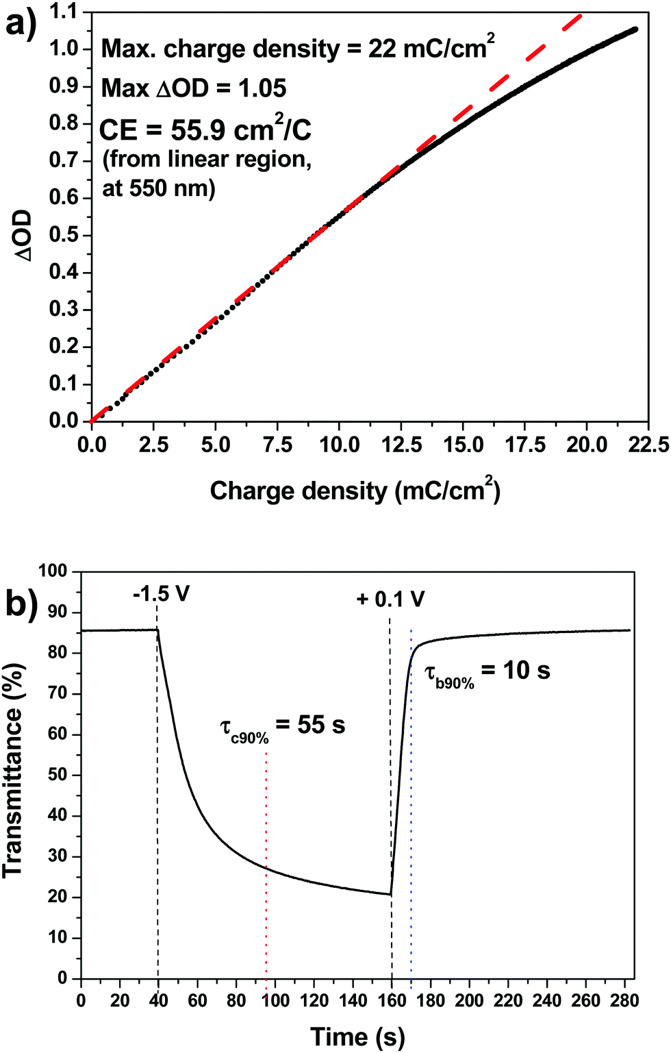 | ||
| Fig. 3 (a) Plot of optical density variation as a function of charge density monitored at 550 nm (bias = −1.5 V) for the sol–gel TiO2 film, giving a CE of 55.9 cm2 C−1. (b) Chronoamperometric transmittance variation curve monitored at the wavelength of 550 nm, obtained by applying a square wave voltage of −1.5 V (colouration) and +0.1 V (bleaching) 120 s each. τc90% and τb90% are the times required to reach 90% of the maximum transmittance modulation for colouration and bleaching. | ||
CE values such as 15 cm2 C−1 at 525 nm,36 10 cm2 C−1 at 550 nm and 50 cm2 C−1 at 750 nm,37 9.93 cm2 C−1 at 630 nm and 13.95 cm2 C−1 at 850 nm in amorphous films and 7.36 cm2 C−1 at 630 nm and 8.07 cm2 C−1 at 850 nm in anatase films,35 and 11.4 cm2 C−1 at 550 nm and 19.2 cm2 C−1 at 750 nm,39 have been reported previously for anatase-containing sol–gel TiO2 films. Our film has the highest CE value yet reported for a sol–gel TiO2 film (at any wavelength) when measured at 550 nm, and as ΔOD is much greater at around λ = 700 nm, it is expected that CE values will be much greater at this wavelength as well. See Table 1 for comparison with other sol–gel and non-sol–gel titania films.
2.3 Chronoamperometry and electrochromic switching kinetics
The chronoamperometric plot is shown in Fig. 3b. Measurements were carried out by applying a square wave voltage of +0.1/−1.5 V for 120 s, and by measuring the corresponding transmittance value at 550 nm. The switching time is defined as the time required for a system to achieve 90% of its full modulation for colouration (τc90%). Recover from 90% of its full modulation for bleaching (τb90%). For colouration τc90% = 55 s, while for the bleaching process τb90% is much quicker at 10 s. This substantial difference between the colouring and bleaching kinetics is related to an asymmetry between the intercalation and de-intercalation processes. Intercalation in anatase-based titanium oxide occurs mainly at the electrode surface in a “top-down” filling mechanism. This means that Li+ intercalation leads to a build-up of LixTiO2 at the electrode/electrolyte interface, which slows down the diffusion process. However, in the de-intercalation process Li+ is easily released from the top of the electrode into the electrolyte, enabling the diffusion of Li+ from the “bottom” of the electrode.55Sol–gel electrochromic anatase TiO2 films typically have bleaching and colouration kinetics in the order of tens of seconds,32τc90% = 136 s and τb90% = 7 s,39 or several minutes.36 Our sol–gel films clearly compare to the best of these for bleaching and colouration kinetics. This makes our sol–gel TiO2 film an excellent material for rapid electrochromic switching in smart windows.
3. Experimental
3.1 Synthesis of sol–gel titania films
The synthesis of these aqueous sols is based on our previously published syntheses for pure titania sols and NPs.40,41 0.2 moles of titanium-iso-propoxide (Merck, 97%) was added to 400 ml of iso-propanol and stirred at 800 rpm. 5.6 ml of concentrated HNO3 (Fluka Puriss PA, 65 wt%) in 20 ml distilled water were added to 50 ml IPA, and this was then added dropwise to the Titanium-iso-propoxide with stirring. This showed no initial precipitation, but after approximately half of the acidic solution was added a thick white precipitate formed, and the stirring rate had to be increased to ∼1200 rpm. After about ¾ of the acidic solution had been added, the precipitate became less viscous, resembling milk, and stirring could be reduced to 800 rpm again. Total addition time was about 30 min. This mixture was then placed on a rotary evaporator and the solvent removed at 60 °C, 100 mbar pressure, to produce a thick white gel. This was redispersed in 400 ml of distilled water, and then the water removed by rotary evaporator at 60 °C, 70 mbar pressure to produce a viscous but powdery yellow gel which never fully dried. Another 400 ml of distilled water was added, the gel redispersed, and the water removed at 60 °C, 70 mbar pressure until a viscous yellow gel had formed. Distilled water was added to make a total volume of 200 ml, and the gel redispersed to create a yellowish-white sol, 1 M concentration.To add 5 wt% polyacrylic acid (PAA) as a surfactant (–CH2CHCO(OH)–, Aldrich PAA N° 323667, Av. MW = 1800), 5 wt% was dissolved in water and added to the sol. The sol appeared slightly more viscous and paler white after PAA addition. This sol could be dried to a powder at 80 °C for transport/storage, and then redispersed in water.
To obtain the nanostructured thin films, 0.05 g ethylcellulose (30–70 mPa s, Sigma Aldrich) dissolved in methanol (10% wt/wt) was added to 5 ml of the TiO2 sol and stirred for 30 minutes at room temperature. Then, the resulting sols were spin coated on 1 cm2 Fluorine-doped tin oxide (FTO, 15 Ω sq−1, Kintec) coated glass substrates at 1500 rpm/30 s and annealed at 430 °C/30 min in air. The resulting 100–120 nm thick film was highly transparent and homogeneous.
3.2 Physical, electrochemical and spectro-electrochemical characterisation
Low-resolution Transmission electron microscope (TEM) investigation of scratched flakes of the nanostructured thin film was performed with a JEM 1400Plus microscope, operating at an acceleration voltage of 120 kV. The film thickness was measured using a Veeco Dektak 150+ Profiler. The morphology of the films was analysed by Scanning Electron Microscopy (SEM) using a Carl Zeiss Auriga40 Crossbeam instrument.Electrochemical measurements of the prepared films were carried out in anhydrous 1 M LiClO4 in propylene carbonate electrolyte solution. A platinum foil served as the counter electrode (area = 4 cm2) and an Ag/AgCl electrode in 1 M LiClO4 in propylene carbonate was used as the reference. All potentials are referred to as the Ag/AgCl reference electrode in 1 M LiClO4 in propylene carbonate. The active area of the electrode was 1 cm × 1 cm. Gold contacts, 150 nm thick with a 5 nm chromium adhesion layer, were prepared by thermal evaporation at one edge of the sample.56 All measurements were carried out within a potential window of −0.9 and +1.5 V determined with cyclic voltammetry. In situ optical spectra were recorded at several potentials after allowing for stabilisation of the optical signal, which required several minutes. The path length of the electrolyte was ∼5 mm during the measurements. Charge measurements between the potential limits were performed via chronopotentiometry, with a potential switched between −1.1 and +1.4 V for a 60 s holding time. Stability tests were performed via chronopotentiometry with 30 s holding time for the bleached and coloured state. Colouration efficiency was calculated from the slope of the optical density as a function of the charge density. All electrochemical measurements were performed with an AUTOLAB PGSTAT302N potentiostat and a Varian Cary 5000 UV-VIS-NIR spectrophotometer.
Conclusions
A pure TiO2 thin film (100–120 nm), made from a green aqueous sol–gel precursor, was spin coated on FTO coated glass and calcined at 430 °C/30 min. The film consists of a mixture of amorphous, anatase, rutile and brookite TiO2 phases. It exhibited excellent electrochromic properties over visible and NIR wavelengths when tested with an electrolyte of LiClO4 in propylene carbonate, enabling Li+ insertion and colouration with an applied bias between +0.1 V to −1.5 V. The film showed a high degree of transparency, exhibiting 86–95% transmittance between 400–1650 nm in the visible and NIR region. It underwent excellent coloration when a voltage was applied, with peak colouration around 700 nm, a transmittance of below 27% in the entire visible region, and between 9% to 60% in the NIR region, the value increasing with greater wavelength. It had a transmittance modulation (ΔT) of 69.7% at 550 nm, 86% at 700 nm and an overall ΔT between 400–1650 nm of 60%. This resulted in a very large change in optical density (ΔOD) of 1.4 at 550 nm and 2.4 at 700 nm. This ΔOD at 550 nm compares to the best previously reported values for sol–gel TiO2, and the ΔOD at 700 nm and all ΔT values are superior to any previously reported sol–gel TiO2 films. Cyclic voltammograms had typical peaks for TiO2 at −1.3 V for colouration and −0.9 V for bleaching, which a high separation of 0.37 V between peaks. The charge density during cathodic colouration was the highest ever reported for anatase based sol–gel films after charging for 25 min at Qc = 50 mC cm−2, and was also extremely high after only 60 s and 120 s with an applied bias of −1.5 V giving Qc = 17.6 and 22 mC cm−2, respectively. Combined with the large ΔOD this led to a high colouration efficiency (CE) of 55.9 cm2 C−1 at 550 nm (−1.5 V), the highest CE value yet reported for a sol–gel TiO2 film at any wavelength. They also possessed very rapid switching times for bleaching and colouring of τb90% = 10 s and τc90% = 55 s, comparable to the best previously reported sol–gel anatase-based TiO2 films. As this film has the highest reported ΔT, ΔOD and CE values ever reported for a sol–gel anatase-based TiO2 film, along with Qc, ΔOD550nm and τb90% and τc90% values virtually equivalent to the best reported, this makes it an excellent candidate material for smart windows and other electrochromic devices and applications. The next step will be to test the stability of these films over repeated electrochemical cycles, and explore their properties further into the IR region.Author contributions
Robert Pullar: conceptualization, methodology, investigation, resources, supervision, writing – original draft, review & editing, revisions, visualization, project administration, funding acquisition. Roberto Giunnuzzi: conceptualization, methodology, investigation, writing – original draft, review & editing, revisions, visualization. Tania Prontera: investigation, methodology. David Tobaldi: methodology, investigation, review & editing. Marco Pugliese: conceptualization, methodology, investigation. Luisa de Marco: investigation, methodology. Pierluigi Cossari: conceptualization, methodology, investigation. Giuseppe Gigli: resources, supervision, project administration, funding acquisition. Vincenzo Maiorano: conceptualization, methodology, resources, supervision, writing – review & editing, project administration, funding acquisition.Conflicts of interest
There are no conflicts to declare.Acknowledgements
This work was developed within the scope of the FCT (Fundação para a Ciência e a Tecnologia, Portugal) project CICECO-Aveiro Institute of Materials, POCI-01-0145-FEDER-007679 (FCT Ref. UID/CTM/50011/2013), financed by national funds through the FCT/MEC and when appropriate co-financed by FEDER under the PT2020 Partnership Agreement. R.C. Pullar wishes to thank FCT grant IF/00681/2015. David Maria Tobaldi is grateful to Portuguese national funds (OE), through FCT, I.P., in the scope of the framework contract foreseen in the numbers 4, 5 and 6 of the article 23, of the Decree-Law 57/2016, of August 29, changed by Law 57/2017, of July 19. The authors gratefully aknowledge Progetto FISR – C.N.R. “Tecnopolo di nanotecnologia e otonica per la medicina di precisione” – CUP B83B17000010001, Apulia regional project “MOSAICOS – MOSAici Interattivi eCO-Sostenibili”, Cod. HOQ3PM3 – CUP B37H17004900007 and Apulia regional project “FONTANAPULIA – Fotocatalizzatori nanostrutturati e radiazione UV per un’acqua più pulita” Cod. WOBV6K5 – CUP B37H17005230007 for funding.References
- C. G. Granqvist, P. C. Lansåker, N. R. Mlyuka, G. A. Niklassona and E. Avendaño, “Progress in chromogenics: New results for electrochromic and thermochromic materials and devices”, Sol. Energy Mater. Sol. Cells, 2009, 93, 2032–2039 CrossRef CAS.
- C. G. Granqvist, Handbook of Inorganic Electrochromic Materials, Elsevier, Amsterdam, The Netherlands, 1995 Search PubMed.
- C. G. Granqvist, “Electrochromic oxides: a band structure approach”, Sol. Energy Mater. Sol. Cells, 1994, 32, 369 CrossRef CAS.
- S. K. Deb, “A Novel Electrophotographic System”, Appl. Opt., 1969, 8, 192–195 CrossRef PubMed.
- S. K. Deb, “Optical and photoelectric properties and colour centres in thin films of tungsten oxide”, Philos. Mag., 1973, vol 27(series 8), 801–822 CrossRef.
- S. K. Deb, “Opportunities and challenges in science and technology of WO3 for electrochromic and related applications”, Sol. Energy Mater. Sol. Cells, 2008, 92, 245–258 CrossRef CAS.
- P. Yang, P. Sun and W. Mai, “Electrochromic energy storage devices”, Mater. Today, 2016, 19, 394–402 CrossRef CAS.
- C. G. Granqvist, M. A. Arvizu, I. Bayrak Pehlivan, H.-Y. Qu, R.-T. Wen and G. A. Niklasson, “Electrochromic materials and devices for energy efficiency and human comfort in buildings - A critical review”, Electrochim. Acta, 2018, 259, 1170–1182 CrossRef CAS.
- C. G. Granqvist, S. Green, G. A. Niklasson, N. R. Mlyuka, S. von Kræmer and P. Georén, “Advances in chromogenic materials and devices”, Thin Solid Films, 2010, 518, 3046–3053 CrossRef CAS.
- C. G. Granqvist, “Electrochromics for smart windows - Oxide-based thin films and devices”, Thin Solid Films, 2014, 564, 1–38 CrossRef CAS.
- V. C. Anitha, A. N. Banerjee and S. W. Joo, “Recent developments in TiO2 as n- and p-type transparent semiconductors - synthesis, modification, properties, and energy-related applications”, J. Mater. Sci., 2015, 50, 7495–7536 CrossRef CAS.
- C. G. Granqvist, P. C. Lansaker, N. R. Mlyuka, G. A. Niklasson and E. Avendano, “Progress in chromogenics - New results for electrochromic and thermochromic materials and devices”, Sol. Energy Mater. Sol. Cells, 2009, 93, 2032–2039 CrossRef CAS.
- Y. Zhang, Z. Jiang, J. Huang, L. Y. Lim, W. Li, J. Deng, D. Gong, Y. Tang, Y. Lai and Z. Chen, “Titanate and titania nanostructured materials for environmental and energy applications - a review”, RSC Adv., 2015, 5, 79479–79510 RSC.
- K. Sauvet, L. Sauques and A. Rougier, “IR electrochromic WO3 thin films: From optimization to devices”, Sol. Energy Mater. Sol. Cells, 2009, 93, 2045–2049 CrossRef CAS.
- P. Chandrasekhar, B. J. Zay, T. McQueeney, A. Scara, D. Ross, G. C. Birur, S. Haapanen, L. Kauder, T. Swanson and D. Douglas, “Conducting Polymer (CP) infrared electrochromics in spacecraft thermal control and military applications”, Synth. Met., 2003, 135–136, 23–24 CrossRef CAS.
- D. Liu, H. Cheng, X. Xing, C. Zhang and W. Zheng, “Thermochromic properties of W-doped VO2 thin films deposited by aqueous sol-gel method for adaptive infrared stealth application”, Infrared Phys. Technol., 2016, 77, 339–343 CrossRef CAS.
- T. D. Swanson and G. C. Birur, “NASA thermal control technologies for robotic spacecraft”, Appl. Therm. Eng., 2003, 23, 1055–1065 CrossRef.
- S.-H. Baeck, K.-S. Choi, T. F. Jaramillo, G. D. Stucky and E. W. McFarland, “Enhancement of photocatalytic and electrochromic properties of electrochemically fabricated mesoporous WO3 thin films”, Adv. Mater., 2003, 15, 1269–1273 CrossRef CAS.
- A. Ghicov, H. Tsuchiya, R. Hahn, J. M. Macak, A. G. Muñoz and P. Schmuki, “TiO2 nanotubes: H+ insertion and strong electrochromic effects”, Electrochem. Commun., 2006, 8, 528–532 CrossRef CAS.
- X. H. Xia, J. P. Tu, J. Zhang, X. L. Wang, W. K. Zhang and H. Huang, “Electrochromic properties of porous NiO thin films prepared by a chemical bath deposition”, Sol. Energy Mater. Sol. Cells, 2008, 92, 628–633 CrossRef CAS.
- S. Roy and C. Chakraborty, “Metallo-Macrocycle Camouflages: Multicolored Electrochromism in a Fe(II) Based Metallo-Supramolecular Macrocycle Utilizing the Redox of Metal Centers and Carbazole Containing Ligand”, ACS Appl. Electron. Mater., 2019, 1, 2531–2540 CrossRef CAS.
- A. Bessière, C. Duhamel, J.-C. Badot, V. Lucas and M.-C. Certiat, “Study and optimization of a flexible electrochromic device based on polyaniline”, Electrochim. Acta, 2004, 49, 2051–2055 CrossRef.
- M. E. Nicho, H. Hu, C. López-Mata and J. Escalante, “Synthesis of derivatives of polythiophene and their application in an electrochromic device”, Sol. Energy Mater. Sol. Cells, 2004, 82, 105–118 CrossRef CAS.
- B. C. Thompson, P. Schottland, K. Zong and J. R. Reynolds, “In situ colorimetric analysis of electrochromic polymers and devices”, Chem. Mater., 2000, 12, 1563–1571 CrossRef CAS.
- I. I. Philips, P. Poole and L. L. Shreir, “Hydride formation during cathodic polarization of Ti—I. Effect of current density on kinetics of growth and composition of hydride”, Corros. Sci., 1972, 12, 855–866 CrossRef.
- S.-D. Mo and W. Y. Ching, “Electronic and Optical Properties of Three Phases of Titanium Dioxide: Rutile, Anatase, and Brookite”, Phys. Rev. B: Condens. Matter Mater. Phys., 1995, 51, 13023–13032 CrossRef CAS PubMed.
- B. J. Morgan and G. W. Watson, “GGA + U description of lithium intercalation into anatase TiO2”, Phys. Rev. B: Condens. Matter Mater. Phys., 2010, 82, 144119 CrossRef.
- V. C. Anitha, A. N. Banerjee and S. W. Joo, “Recent developments in TiO2 as n- and p-type transparent semiconductors: synthesis, modification, properties, and energy-related applications”, J. Mater. Sci., 2015, 50, 7495–7536 CrossRef CAS.
- C. J. Dahlman, Y. Tan, M. A. Marcus and D. J. Milliron, “Spectroelectrochemical Signatures of Capacitive Charging and Ion Insertion in Doped Anatase Titania Nanocrystals”, J. Am. Chem. Soc., 2015, 137, 9160–9166 CrossRef CAS PubMed.
- S. R. Meher and L. Balakrishnan, “Sol–gel derived nanocrystalline TiO2 thin films: A promising candidate for self-cleaning smart window applications”, Mater. Sci. Semicond. Process., 2014, 26, 251–258 CrossRef CAS.
- M. A. Aegerter, C. O. Avellaneda, A. Pawlicka and M. Atik, “Electrochromism in materials prepared by the sol-gel process”, J. Sol-Gel Sci. Technol., 1997, 8, 689–696 CAS.
- M. Nabavi, S. Doeuff, C. Sanchez and J. Livage, “Sol-gel synthesis of electrochromic films”, Mater. Sci. Eng. B, 1989, 3, 203–207 CrossRef.
- N. Ozer, F. Tepehan and N. Bozkurt, “An “all-gel” electrochromic device”, Thin Solid Films, 1992, 219, 193–198 CrossRef CAS.
- A. Hagfeld, N. Vlachopoulos, S. Gilbert and M. Grezel, in Optical Materials Technology for Energy Efficiency and Solar Energy Conversion XIII (SPIE, Bellingham, Whashington, USA, 1994), SPIE, 1994, 2255, 297 Search PubMed.
- Z. Wang and X. Hu, “Fabrication and electrochromic properties of spin-coated TiO2 thin films from peroxo-polytitanic acid”, Thin Solid Films, 1999, 352, 62–65 CrossRef CAS.
- N. N. Dinh, N. Th. T. Oanh, P. D. Long, M. C. Bernard, A. Hugot-Le Goff, “Electrochromic properties of TiO2 anatase thin films prepared by a dipping sol–gel method”, Thin Solid Films, 2003, 423, 70–76 CrossRef CAS.
- T. Ivanova, A. Harizanova, T. Koutzarova, N. Krins and B. Vertruyen, “Electrochromic TiO2, ZrO2 and TiO2–ZrO2 thin films by dip-coating method”, Mater. Sci. Eng. B, 2009, 165, 212–216 CrossRef CAS.
- W. Niu, G. Wang, X.-D. Liu, J. Tang and X.-G. Bi, “Preparation and Electrochromic Performance of TiO2 Thin Film”, Int. J. Electrochem. Sci., 2015, 10, 2613–2620 CAS.
- A. Verma, A. Basu, A. K. Bakhshi and S. A. Agnihotry, “Structural, optical and electrochemical properties of sol–gel derived TiO2 films: Annealing effects”, Solid State Ionics, 2005, 176, 2285–2295 CrossRef CAS.
- D. M. Tobaldi, R. C. Pullar, A. F. Gualtieri, M. P. Seabra and J. A. Labrincha, “Sol-gel Synthesis and Characterisation of Pure, W-, Ag-, and W/Ag co-Doped TiO2 Nanopowders”, Chem. Eng. J., 2013, 214, 364–375 CrossRef CAS.
- D. M. Tobaldi, R. C. Pullar, R. Binions, A.-B. Jorge-Sobrido, P. F. McMillan, M. Saeli, M. P. Seabra and J. A. Labrincha, “Influence of sol counter-ions on the visible-light induced photocatalytic behaviour of TiO2 nanoparticles”, Catal. Sci. Technol., 2014, 4, 2134–2146 RSC.
- R. A. Patil, R. S. Devan, Y. Liou and Y.-R. Ma, “Efficient electrochromic smart windows of one- dimensional pure brookite TiO2 nanoneedles”, Sol. Energy Mater. Sol. Cells, 2016, 147, 240–245 CrossRef CAS.
- Y. Chen, X. Li, Z. Bi, X. He, G. Li, X. Xu and X. Gao, “Design and construction of hierarchical TiO2 nanorod arrays by combining layer-by-layer and hydrothermal crystallization techniques for electrochromic application”, Appl. Surf. Sci., 2018, 440, 217–223 CrossRef CAS.
- S. Liu, X. Zhang, P. Sun, C. Wang, Y. Wei and Y. Liu, “Enhanced electrochromic properties of a TiO2 nanowire array via decoration with anatase nanoparticles”, J. Mater. Chem. C, 2014, 2, 7891–7896 RSC.
- D. M. Tobaldi, R. C. Pullar, M. Leoni, M. P. Seabra and J. A. Labrincha, “Nanosized Titania Modified with Tungsten and Silver: Microstructural Characterisation of a Multifunctional Material”, Appl. Surf. Sci., 2013, 287, 276–281 CrossRef CAS.
- H. Lindstrom, S. Sodergren, A. Solbrand, H. Rensmo, J. Hjelm, A. Hagfeldt and S. E. Lindquist, “Li+ Ion Insertion in TiO2 (Anatase). 1. Chronoamperometry on CVD Films and Nanoporous Films”, J. Phys. Chem. B, 1997, 101, 7710–7716 CrossRef.
- H. Lindstrom, S. Sodergren, A. Solbrand, H. Rensmo, J. Hjelm, A. Hagfeldt and S. E. Lindquist, “Li+ Ion Insertion in TiO2 (Anatase). 2. Voltammetry on Nanoporous Films”, J. Phys. Chem. B, 1997, 101, 7717–7722 CrossRef.
- Q. Wang, Z. Wen and J. Li, “Solvent-Controlled Synthesis and Electrochemical Lithium Storage of One-Dimensional TiO2 Nanostructures”, Inorg. Chem., 2006, 45, 6944–6949 CrossRef CAS PubMed.
- N. Nang Dinh, N. Minh Quyen, D. N. Chung, M. Zikova and V. Van Truong, “Highly-efficient electrochromic performance of nanostructured TiO2 films made by doctor blade technique”, Sol. Energy Mater. Sol. Cells, 2011, 95, 618–623 CrossRef CAS.
- C. A. Triana, C. G. Granqvist and G. A. Niklasson, “Electrochromic Properties of Li + -Intercalated Amorphous Tungsten (aWO3-x) and Titanium (aTiO2-x) Oxide Thin Films”, J. Phys.: Conf. Ser., 2014, 559, 1–6 CrossRef.
- Z. S. Khalifa, “Electronic structure changes of TiO2 thin films due to electrochromism”, Sol. Energy Mater. Sol. Cells, 2014, 124, 186–191 CrossRef CAS.
- E. Şilik, S. Pat, S. Özen, R. Mohammadigharehbagh, H. H. Yudar, C. Musaoğlu and Ş. Korkmaz, “Electrochromic properties of TiO2 thin films grown by thermionic vacuum arc method”, Thin Solid Films, 2017, 640, 27–32 CrossRef.
- S. Zhang, S. Cao, T. Zhang and J. Y. Lee, “Plasmonic Oxygen-Deficient TiO2-x Nanocrystals for Dual-Band Electrochromic Smart Windows with Efficient Energy Recycling”, Adv. Mater., 2020, 32, 2–9 Search PubMed.
- N. Akkurt, S. Pat, R. Mohammadigharehbagh, M. Özgür, U. Demirkol, A. Olkun and Ş. Korkmaz, “Investigation of TiO2 thin films as a cathodic material for electrochromic display devices”, J. Mater. Sci.: Mater. Electron., 2020, 31, 9568–9578 CrossRef CAS.
- S. Moitzheim, S. De Gendt and P. M. Vereecken, “Investigation of the Li-Ion Insertion Mechanism for Amorphous and Anatase TiO2 Thin-Films”, J. Electrochem. Soc., 2019, 166, A1–A9 CrossRef CAS.
- R. Giannuzzi, F. De Donato, L. De Trizio, A. G. Monteduro, G. Maruccio, R. Scarfiello, A. Qualtieri and L. Manna, “Tunable Near-Infrared Localized Surface Plasmon Resonance of F, In-Codoped CdO Nanocrystals”, ACS Appl. Mater. Interfaces, 2019, 11, 39921–39929 CrossRef CAS PubMed.
| This journal is © The Royal Society of Chemistry 2022 |