DOI:
10.1039/D1YA00024A
(Paper)
Energy Adv., 2022,
1, 38-44
An aromatic ionomer in the anode catalyst layer improves the start-up durability of polymer electrolyte fuel cells†
Received
11th October 2021
, Accepted 22nd November 2021
First published on 23rd November 2021
Abstract
A sulfonated polyphenylene ionomer (SPP-QP) was used as a catalyst layer binder in polymer electrolyte fuel cells. SPP-QP functioned well in the proton-conducting thin layers to show high electrochemically active surface area (ECSA) for the Pt catalysts. When used as the cathode binder, however, specific adsorption of SPP-QP on the Pt catalyst lowered the oxygen reduction reaction (ORR) activity, resulting in lower fuel cell performance compared to that using Nafion binder. In contrast, SPP-QP supported the hydrogen oxidation reaction (HOR) in the anode, with a negligibly small overpotential, similar to that for Nafion. Furthermore, the fuel cell with SPP-QP as the anode binder (SPP-QP(a)-cell) exhibited improved durability in a gas exchange cycle test simulating start-up conditions (according to the protocol suggested by the Fuel Cell Commercialization Conference of Japan). After 1000 cycles, the remaining ECSA was 37% for the SPP-QP(a)-cell, compared to 19% for the Nafion(a)-cell. The better durability was further demonstrated in the I–V curves, where the cell voltage remaining at a current density of 0.8 A cm−2 was 80% of the pre-test value for the SPP-QP(a)-cell compared to 47% for the Nafion(a)-cell. The specific adsorption of SPP-QP on the Pt catalyst suppressed the unfavorable ORR in the anode and accordingly the so-called reverse current reaction under start-up conditions, mitigating the degradation of the cathode catalyst layer.
Introduction
Fuel cells are clean, efficient energy generating devices that should play a crucial role in the realization of a hydrogen-based society. Among several types of fuel cells, polymer electrolyte fuel cells (PEFCs) using proton exchange membranes as the electrolyte have attracted considerable interest, in particular, for automobile and residential applications over the past decade. In order for PEFCs to become more widespread in the global market, improvement of the performance and durability as well as cost reduction are required.1,2 To address those issues, significant efforts have been devoted to the development of component materials, including electrocatalysts and electrolyte membranes.3–6 Proton-conductive ionomers are used as binders in the catalyst layers and are thus particularly important in terms of how they affect the electrocatalytic activity for the oxygen reduction and hydrogen oxidation reactions (ORR and HOR) in operating PEFCs. Currently, perfluorinated ionomers such as Nafion are most used in commercial PEFCs due to their high proton conductivity and chemical stability. However, the fully fluorinated chemical structure leads to high production costs. Their glass transition temperature is relatively low (ca. 100–110 °C) and becomes even lower under hydrated conditions, which limits the upper operable temperature of PEFCs, whereas the US Department of Energy (DOE) and the New Energy and Industrial Technology Development Organization (NEDO) of Japan both target an operating temperature of 120 °C within the next decade. Therefore, there is a strong demand for proton-conductive ionomers with higher thermal stability and lower production cost.7–9 Aromatic ionomers are some of the more promising candidates and have been extensively investigated. For example, sulfonated poly(phenylene)s,10,11 poly(ether ether ketone)s,12 poly(arylene ether sulfone)s13 and polyimides14 can be found as proton-exchange membranes in the literature, and some of these have been applied as electrode binders.15–21 Recently, E. Balogun et al. reported high fuel cell performance above 1 W cm−2 using their original polyphenylene ionomer.22 We have developed polyphenylene ionomer (SPP-QP) membranes, which consist only of phenylene rings and sulfonic acid groups. Unlike typical aromatic ionomers, the absence of heteroatoms in groups such as ethers and sulfones in the polymer main chain contributed to excellent chemical stability, in addition to high proton conductivity over a wide humidity range, comparable to that of Nafion. High fuel cell performance and durability have been achieved with the SPP-QP membrane in cells in which Nafion was used in the catalyst layers.23 As a next step, it is of great interest to investigate the properties of SPP-QP as an electrode binder. In the present study, SPP-QP was evaluated as the catalyst layer binder for both the anode and cathode. It is well-known that the carbon support in the cathode catalyst layer corrodes during the cell start-up, most likely due to the high cathode potential (>1.5 V vs. RHE) due to the reverse current reaction caused by the ORR in the anode (Fig. 1).24,25 In the literature, there have been several attempts to address this issue, including the use of more corrosion-resistant catalysts and support materials in the cathode.26,27 We report herein that strong “specific” adsorption of SPP-QP on the platinum surface suppressed the reduction of oxygen remaining in the anode as a reverse current reaction, and thus that it mitigated the degradation of the cathode catalyst layers in the accelerated durability test (or gas exchange durability test) simulating start-up conditions. Post-test analyses of the catalyst layers and fuel cell performance were carried out to support this claim.
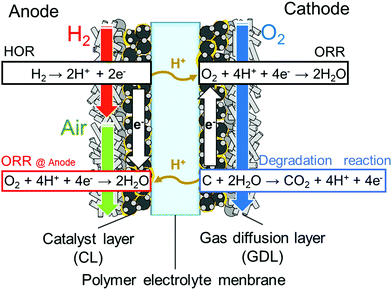 |
| | Fig. 1 Mechanism of reverse current reaction during start-up of a PEFC. | |
Experimental
Preparation of membrane electrode assembly (MEA)
The SPP-QP (IEC = 2.4 mequiv g−1) ionomer was synthesized according to the literature. A 5 wt% ionomer solution in dimethylacetamide (DMAc) was filtered through a 1 μm disk filter prior to use. Nafion solution (IEC = 0.95–1.03 mequiv g−1, D-521) was purchased from Dupont. A catalyst ink containing SPP-QP was prepared from the ionomer solution, Pt/CB (TEC10E50E, Tanaka Kikinzoku Kogyo, K. K.), ultrapure water, and DMAc. A catalyst ink containing Nafion was prepared from the ionomer solution, Pt/CB (TEC10E50E, Tanaka Kikinzoku Kogyo, K. K.), ultrapure water, and ethanol. In both inks, the mass ratio of the ionomer to carbon (I/C) and solid/liquid ratio were set at 0.7 and 0.07 wt%, respectively. The mixture was ball-milled in a zirconia pod containing 20 5 mm zirconia beads at 270 rpm for 30 min. The resulting ink was sprayed onto one side of a Nafion membrane (NRE211, Dupont) using the pulse-swirl-spray technique (PSS, Nordson). Then, the catalyst ink was similarly sprayed onto the other side of the membrane to obtain a catalyst-coated membrane (CCM). The geometric electrode area was 29.16 cm2 and the Pt loading was 0.50 ± 0.05 mg cm−2. The CCM was dried at 60 °C overnight. The CCM was hot-pressed at 140 °C and 10 kgf cm−2 for 3 min and then sandwiched by two gas diffusion layers (29BC, SGL Carbon Group) and assembled into a JARI cell (Japan Automobile Research Institute).
Initial activation and cleaning of the cell
The single cell was placed in a fuel cell evaluation system (Panasonic Co.). For all cells with the catalyst layer containing SPP-QP or Nafion, initial activation28 was carried out supplying oxygen to the SPP-QP electrode and hydrogen to the Nafion electrode at 80 °C and 100% RH at a constant current density of 0.2 A cm−2 for 12 h. Then, hydrogen was supplied to the anode and nitrogen (100 mL min−1) was supplied to the cathode, respectively, and the potential was swept between 0.075 and 1.0 V at a sweep rate of 20 mV s−1 for 40 cycles. For the cell with the catalyst layer containing SPP-QP, nitrogen was exchanged to oxygen and the cell was operated at a constant current density of 1.0 A cm−2 for 48 h to remove the residual DMAc solvent from the catalyst layer.
Fuel cell operation
The cell was operated at 80 °C and 100% RH. Cyclic voltammograms (CV) were obtained with a potential sweep between 0.075 and 1.0 V at a sweep rate of 20 mV s−1 with 100 mL min−1 of hydrogen supply at the anode and nitrogen atmosphere in the cathode. From the obtained hydrogen adsorption peak and the Pt oxidation peak in the CV, the electrochemically active surface area (ECSA) and Pt oxidation charge (QPt) were calculated, respectively. The QPt was calculated from the anodic charge in the CV between 0.7–0.85 V subtracting the electric double layer charge (around 0.4 V) as the baseline. The polarization curves were measured at a constant current mode with hydrogen supplied to the anode and oxygen supplied to the cathode. The gas utilization percentages were 70% for hydrogen and 40% for oxygen. Polarization at the anode was measured by a hydrogen pump test22 under each measurement condition supplying hydrogen at 1 L min−1.
Accelerated durability test
Gas exchange durability test was conducted at 45 °C with the protocol shown in Table 1.29
Table 1 Protocol for gas exchange durability test
|
|
Anode |
Cathode |
| Step |
Time (s) |
Gas |
RH (%) |
Flow rate (mL min−1) |
Gas |
RH (%) |
Flow rate (mL min−1) |
| 1 |
90 |
Air |
0 |
360 |
Air |
100 |
360 |
| 2 |
90 |
H2 |
100 |
38 |
Air |
100 |
360 |
| 3 |
60 |
N2 |
0 |
180 |
N2 |
0 |
180 |
The degradation of the cathode catalyst was monitored by measuring CV every 200 cycles at 45 °C and 100% RH.
FIB-SIM
After the durability test, the recovered MEA was disassembled, sliced by a focused ion beam and analyzed by scanning ion microscopy (FIB, FB-2200, Hitachi High-Technologies Co., Ltd).
Results and discussion
Evaluation of the cell using SPP-QP as the cathode
Fig. 2 shows cyclic voltammograms of the cells using SPP-QP and Nafion as the cathode binder (hereinafter referred to as the SPP-QP(c)-cell and Nafion(c)-cell, respectively) at 80 °C. The CVs differed between the two cells, in particular, in the high potential region (0.6–1.0 V vs. RHE). At 100% RH, SPP-QP (c)-cell showed a characteristic peak around 0.2 V assignable to adsorption/desorption of the sulfonic acid groups in addition to the hydrogen adsorption/desorption. ECSA values calculated from the hydrogen adsorption peaks were 45.1 m2 g−1 for SPP-QP(c)-cell and 44.4 m2 g−1 for Nafion(c)-cell, respectively, suggesting that the ionomers in both cathode catalyst layers functioned similarly as proton sources for the catalysts. In contrast, the Pt oxidation peak shifted to higher potentials for the SPP-QP(c)-cell than for the Nafion(c)-cell. The QPt value calculated from the Pt oxidation peak (0.7–0.85 V) was 29.1 C g−1 for the SPP-QP(c)-cell, which was nearly exactly half than that (62.5 C g−1) for the Nafion(c)-cell. These results indicate that SPP-QP was more strongly adsorbed on the Pt catalyst and thus suppressed the surface oxidation by excluding water in the double layer, although its bulk water absorbability was larger. The differences in the QPt values became even larger at lower humidity (53% RH, Table 2), further supporting this idea, since, at lower humidity, the ionomer concentration became higher and there was less water available.
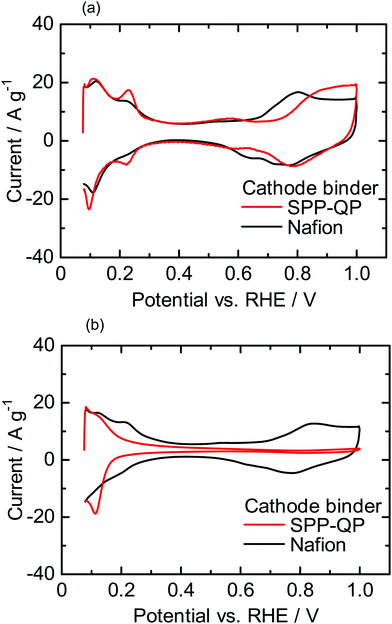 |
| | Fig. 2 Cyclic voltammograms for the cathodes of the SPP-QP(c)-cell and Nafion(c)-cell at 80 °C: (a) 100% RH and (b) 53% RH. | |
Table 2 ECSA and QPt values for the cathodes of the SPP-QP(c)-cell and Nafion(c)-cell
|
|
100% RH |
53% RH |
| ECSA (m2 g−1) |
Q
Pt (C g−1) |
ECSA (m2 g−1) |
Q
Pt (C g−1) |
| SPP-QP(c)-cell |
45.1 ± 0.3 |
29.1 ± 4.1 |
29.8 ± 4.0 |
0 |
| Nafion(c)-cell |
44.4 ± 0.2 |
62.5 ± 3.7 |
35.0 ± 1.1 |
37.0 ± 3.1 |
Fig. 3a shows I–V curves and ohmic resistance of the SPP-QP(c)-cell or Nafion(c)-cell at 80 °C and 100% RH. The ohmic resistances were comparable and constant for both cells (ca. 0.05 Ω cm2) and reasonable for the proton conductivity and thickness of the Nafion membrane, indicating that the interfacial contact between the membrane and the catalyst layers containing the Nafion and SPP-QP binders was excellent. The performance of the SPP-QP(c)-cell was lower than that of Nafion(c)-cell. From the IR-corrected I–V curves (Fig. S1, ESI†), the lower performance was due to the larger cathodic overpotential. The mass activity (MA) of the Pt catalyst at 0.85 V was 42.8 A g−1 for the SPP-QP(c)-cell, which was ca. 21% that for the Nafion(c)-cell (201 A g−1). The fuel cell performance became even lower at 53% RH (Fig. 3b), resulting in a lower MA, 18.8 A g−1, for the SPP-QP(c)-cell compared to 147 A g−1 for the Nafion(c)-cell. The results are in good accordance with the CV curves, as mentioned above, where the specific absorption of the SPP-QP binder on the Pt surface became stronger at lower humidity and at higher potential.
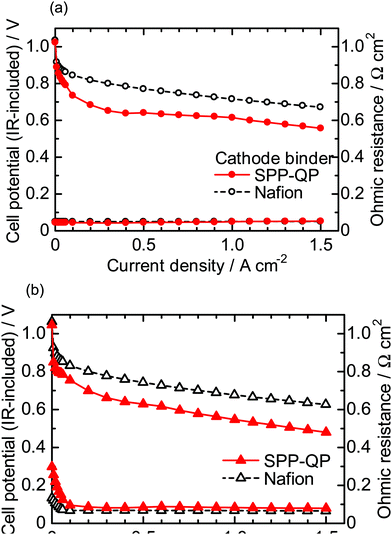 |
| | Fig. 3
I–V curves (IR-included) and ohmic resistances for the SPP-QP(c)-cell and Nafion(c)-cell at 80 °C: (a) 100% RH and (b) 53% RH. | |
Initial performance of the cell using SPP-QP as the anode binder
Fig. 4 shows the anodic polarization of a cell using SPP-QP and Nafion as the anode binder (hereinafter referred to as the SPP-QP(a)-cell and Nafion(a)-cell, respectively) at 80 °C, 100% RH and 53% RH (note that cathode binder was Nafion for both cells). At 100% RH, the anodic polarization was negligibly small at current densities up to 1.5 A cm−2 for both cells. At 53% RH, the polarization was somewhat larger, 50 mV for the Nafion(a)-cell and 81 mV for the SPP-QP(a)-cell at the current density of 0.9 A cm−2 due to the lower proton conductivity of the binders. The anodic polarizations were much smaller than the cathodic polarizations (Fig. 3) at 80 °C 100% RH and 53% RH, implying that SPP-QP as well as Nafion functioned well as the proton conductor for the HOR.
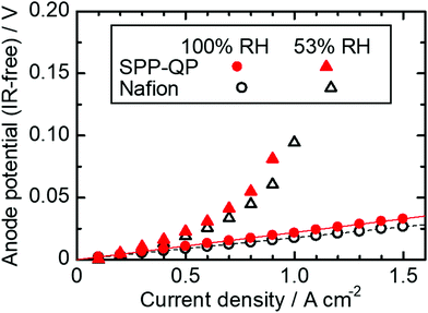 |
| | Fig. 4 Anodic polarization for the SPP-QP(a)-cell and Nafion(a)-cell at 80 °C. | |
Fig. 5 shows I–V curves and ohmic resistances of the SPP-QP(a)-cell and Nafion(a)-cell at 80 °C (a) 100% RH, (b) 53% RH. The ohmic resistances were similar to those of the SPP-QP(c)-cell and Nafion(c)-cell in Fig. 3, indicating reasonable compatibility of the SPP-QP-based anode catalyst layer and Nafion membrane. The SPP-QP(a)-cell showed slightly lower cell performance than the Nafion(a)-cell (e.g., lower by 49 mV at 100% RH and 50 mV at 53% RH at a current density of 0.15 A cm−2), where the cathode performance was responsible (Fig. S2, ESI†). In order to achieve complete removal of the residual solvent from the SPP-QP binder, a stringent cleaning process was applied to the SPP-QP(a) cell (see the Experimental section) which might have caused such differences in the cathode performance. Since the performance difference was rather minor, both cells were subjected to the durability test.
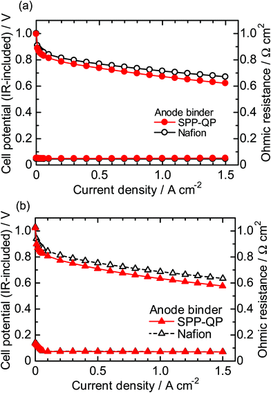 |
| | Fig. 5 Polarization curves (IR-included) and ohmic resistances for the SPP-QP(a)-cell and Nafion(a)-cell at 80 °C: (a) 100% RH and (b) 53% RH. | |
Accelerated durability test simulating fuel cell start-up
The durability of the cathodes of the SPP-QP(a)-cell and Nafion(a)-cell was examined via a gas exchange cycle test under accelerated conditions. Degradation of the cathode catalyst layers was monitored electrochemically via CVs obtained every 200 cycles. Fig. 6 shows the changes in the CVs during the gas exchange cycle test.29 In both cells, the current density based on hydrogen adsorption/desorption (from 0.075 to 0.4 V), electric double layer (from 0.4 to 0.7 V), and surface Pt oxidation/reduction (from 0.7 to 1.0 V) decreased with increasing cycle number. The results show that the gas exchange cycles induced the reverse current reaction, causing deterioration of the carbon support and loss of the Pt in the cathode catalyst layers. In order to monitor this process, ECSA and its retention calculated therefrom are plotted as a function of cycle number in Fig. 7. The initial ECA for the SPP-QP(a)-cell was 48.1 m2 g−1, smaller than that for the Nafion(a)-cell (56.9 m2 g−1). Although the initial ECA was lower, the decay was smaller for the SPP-QP(a)-cell, retaining a higher ECSA (17.9 m2 g−1, 37% retention) than that (10.5 m2 g−1, 19% retention) for the Nafion(a)-cell after 1000 cycles. The average decay of the ECSA was 0.03 m2 g−1 cycle (or 0.45 m2 g−1 h) and 0.05 m2 g−1 cycle (or 0.70 m2 g−1 h) for the SPP-QP(a)-cell and Nafion(a)-cell, respectively. The superior durability of the ECSA in the cathode of the SPP-QP(a)-cell was due to the stronger specific adsorption of SPP-QP on the Pt catalyst at higher potentials, as discussed above. The ORR occurring at the anode (under start-up conditions) was suppressed, mitigating the reverse current reaction, increase of the cathode potential, and, accordingly, corrosion of the carbon support in the cathode catalyst layer.20
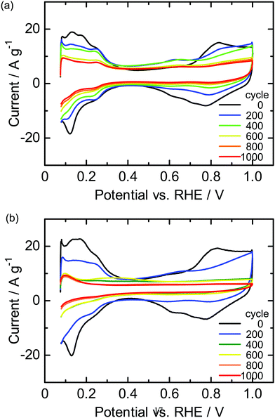 |
| | Fig. 6 CVs for the cathode of the (a) SPP-QP(a)-cell and (b) Nafion(a)-cell during the gas exchange cycle test. | |
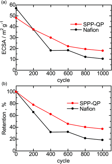 |
| | Fig. 7 (a) ECSA and (b) ESCA retention for the SPP-QP(a)-cell and Nafion(a)-cell during the gas exchange cycle test. | |
After 1000 cycles, the I–V curves and ohmic resistance were re-evaluated and compared with the initial performance (Fig. 8). Both cells exhibited lower I–V performance and higher ohmic resistance after the test due to the degradation of the cathode catalyst layers. The performance loss was less significant for the SPP-QP(a)-cell than for the Nafion(a)-cell. For example, the cell voltages measured at a current density of 0.8 A cm−2 were 0.56 V (80% of the initial) for the SPP-QP(a)-cell and 0.34 V (47% of the initial) for the Nafion(a)-cell. These results are consistent with the ECSA losses mentioned above. Although the initial ohmic resistance was very similar (ca. 0.05 Ω cm−2) for both the SPP-QP(a)-cell and Nafion(a)-cell, the post-test ohmic resistance differed: 0.12 Ω cm−2 for the SPP-QP(a)-cell and 0.22 Ω cm−2 for the Nafion(a)-cell. The carbon support in the cathode catalyst layer would have deteriorated by the gas replacement durability test, and the influence was greater in the Nafion (a) cell.
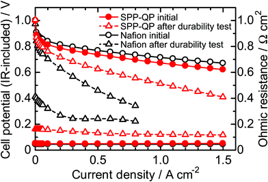 |
| | Fig. 8 IR-included polarization curve and Ohmic resistance of the SPP-QP(a)-cell and Nafion(a)-cell before and after the gas exchange cycle test at 80 °C and 100% RH. | |
Post-test analyses of the cathode catalyst layers
Fig. 9 compares cross-sectional scanning ion microscopic (SIM) images of the cathode catalyst layers at three different locations of the cells before and after the 1000-cycle gas exchange test (SIM was used rather than SEM to obtain more distinct contrast in the images). The thickness of the catalyst layers was initially ca. 17 μm. After the test, the thickness was smaller than 6 μm at the inlet, center, and outlet for the Nafion(a)-cell. These results were indicative of the significant degradation of the cathode catalyst layers associated with the carbon corrosion. In contrast, the SPP-QP(a) cell retained its original thickness, specifically at the inlet (17 μm). However, even for the SPP-QP(a)-cell, the catalyst layer became thinner at the center and the outlet, probably because of the longer time period during which the mixed gas remained downstream.
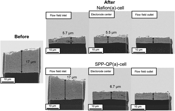 |
| | Fig. 9 SIM images of the cathode catalyst layer of the SPP-QP(a)-cell and Nafion(a)-cell before and after the gas exchange cycle test. | |
Conclusions
Our in-house sulfonated polyphenylene ionomer (SPP-QP) was evaluated as a catalyst layer binder for the anode and the cathode, in separate measurements. From the CVs, the cell using SPP-QP as the cathode binder (SPP-QP(c)-cell) exhibited an ECSA value comparable with that for the cell using Nafion as the cathode binder (Nafion(c)-cell) at high (100% RH) and low (53% RH) humidity, indicating that SPP-QP functioned well as a proton conductor in the catalyst layer. However, the Pt oxidation peak for the SPP-QP(c)-cell shifted to higher potentials, and the QPt value was half that of the Nafion(c)-cell because of the strong specific adsorption of the SPP-QP ionomer on the Pt catalyst, particularly at low humidity. Therefore, the SPP-QP(c)-cell exhibited lower fuel cell performance than that for the Nafion(c)-cell. At 53% RH, the difference in mass activity (MA) of the cathode catalyst was ca. 7.8-fold. As the anode binder, SPP-QP functioned well in a fuel cell (SPP-QP(a)-cell), with negligibly small anodic overpotential and only slightly inferior I–V performance compared to the Nafion(a)-cell, even at 53% RH. The specific adsorption of SPP-QP on Pt at higher potentials contributed much to improving the durability of the cathode catalyst layer during the start-up (or gas exchange) durability test. The cathode ECSA values remaining for the SPP-QP(a)-cell and Nafion(a)-cell after 1000 cycles were 17.9 m2 g−1 (37% remaining) and 10.5 m2 g−1 (19% remaining). In other words, the reverse current reaction was suppressed under start-up conditions with the SPP-QP as the anode binder. The post-test I–V performance was such that the cell voltages measured at a current density of 0.8 A cm−2 were 0.56 V (80% remaining) for the SPP-QP(a)-cell and 0.34 V (47% remaining) for the Nafion(a)-cell. The ohmic resistance after the test was lower for the SPP-QP(a)-cell (0.12 Ω cm−2) than for the Nafion(a)-cell (0.22 Ω cm−2). In the Nafion(a)-cell, the interfacial compatibility between the Nafion membrane and the cathode catalyst layer deteriorated due to the degradation of the cathode catalyst layer. In the Nafion(a)-cell, the cathode catalyst layer became thinner than 6 μm in all areas (initial thickness 17 μm). In contrast, the SPP-QP(a)-cell retained the initial thickness of the cathode catalyst layer, specifically at the inlet (16 μm). We have thus, demonstrated that the use of aromatic ionomer as the anode binder, which exhibited strong specific adsorption on Pt, was effective in mitigating the cathode carbon corrosion during a gas exchange test simulating start-up conditions, with little or no impact on the I–V performance.
Author contributions
Toshiki Tanaka: investigation, writing. Makoto Uchida: conceptualization, methodology, reviewing and editing, funding aquisiton. Kenji Miyatake: supervision, writing, reviewing and editing, funding aquisiton, and project administration.
Conflicts of interest
There are no conflicts to declare.
Acknowledgements
We thank Dr Hiroyuki Uchida (Emeritus Professor at University of Yamanashi) for fruitful discussion. This work was partly supported by the New Energy and Industrial Technology Development Organization (NEDO), the Ministry of Education, Culture, Sports, Science and Technology (MEXT), Japan, through Grants-in-Aid for Scientific Research (18H05515), Japan Science and Technology (JST) through SICORP (JPMJSC18H8), JKA promotion funds from AUTORACE, and by the Thermal and Electric Energy Technology Foundation.
Notes and references
- L. Carrette, K. A. Friedrich and U. Stimming, Fuel Cells, 2001, 1, 5–39 CrossRef CAS.
- J. M. Thomas, P. P. Edwards, P. J. Dobson and G. P. Owen, J. Energy Chem., 2020, 51, 405–415 CrossRef PubMed.
- H. A. Gasteiger, S. S. Kocha, B. Sompalli and F. T. Wagner, Appl. Catal., B, 2005, 56, 9–35 CrossRef CAS.
- M. Watanabe, D. A. Tryk, M. Wakisaka, H. Yano and H. Uchida, Electrochim. Acta, 2012, 84, 187–201 CrossRef CAS.
- L. Osmieri, J. Park, D. A. Cullen, P. Zelenay, D. J. Myers and K. C. Neyerlin, Curr. Opin. Electrochem., 2021, 25, 100627 CrossRef CAS.
- H. Zhang and P. K. Shen, Chem. Rev., 2012, 112, 2780–2832 CrossRef CAS PubMed.
- M. P. Rodgers, L. J. Bonville, H. R. Kunz, D. K. Slattery and J. M. Fenton, Chem. Rev., 2012, 112, 6075–6103 CrossRef CAS PubMed.
- W. Liu, T. Suzuki, H. Mao and T. Schmiedel, J. Electrochem. Soc., 2013, 50, 51–64 Search PubMed.
- Y. Prykhodko, K. Fatyeyeva, L. Hespel and S. Marais, Chem. Eng. J., 2021, 409, 127329 CrossRef CAS.
- M. Adamski, N. Peressin and S. Holdcroft, Mater. Adv., 2021, 2, 4966–5005 RSC.
- T. Oshima, M. Yoshizawa-Fujita, Y. Takeoka and M. Rikukawa, ACS Omega, 2016, 1, 939–942 CrossRef CAS PubMed.
- J. Jiang, X. Zhu, H. Qian, J. Xu, Z. Yue, Z. Zou and H. Yang, Sustainable Energy Fuels, 2019, 3, 2426–2434 RSC.
- R. Mukherjee, A. K. Mandal and S. Banerjee, e-Polym., 2020, 20, 430–442 CAS.
- A. G. Kumar, A. Singh, H. Komber, B. Voit, B. R. Tiwari, M. T. Noori, M. M. Ghangrekar and S. Banerjee, ACS Appl. Mater. Interfaces, 2018, 10, 14803–14817 CrossRef CAS PubMed.
- T. Yoda, T. Shimura, B. Bae, K. Miyatake, M. Uchida, H. Uchida and M. Watanabe, Electrochim. Acta, 2009, 54, 4328–4333 CrossRef CAS.
- T. Yoda, T. Shimura, B. Bae, K. Miyatake, M. Uchida, H. Uchida and M. Watanabe, Electrochim. Acta, 2010, 55, 3464–3470 CrossRef CAS.
- T. Omata, M. Uchida, H. Uchida, M. Watanabe and K. Miyatake, Phys. Chem. Chem. Phys., 2012, 14, 16713–16718 RSC.
- T. Omata, M. Tanaka, K. Miyatake, M. Uchida, H. Uchida and M. Watanabe, ACS Appl. Mater. Interfaces, 2012, 4, 730–737 CrossRef CAS PubMed.
- H. Nguyen, F. Lombeck, C. Schwarz, P. A. Heizmann, M. Adamski, H. F. Lee, B. Britton, S. Holdcroft, S. Vierrath and M. Breitwieser, Sustainable Energy Fuels, 2021, 5, 3687–3699 RSC.
- J. E. Chae, S. J. Yoo, J. Y. Kim, J. H. Jang, S. Y. Lee, K. H. Song and H. Kim, Int. J. Hydrogen Energy, 2020, 45, 32856–32864 CrossRef CAS.
- X. Pu, Y. Duan, J. Li, C. Ru and C. Zhao, J. Power Sources, 2021, 493, 229671 CrossRef CAS.
- E. Balogun, M. Adamski and S. Holdcroft, J. Electrochem. Soc., 2020, 167, 084502 CrossRef CAS.
- J. Miyake, R. Taki, T. Mochizuki, R. Shimizu, R. Akiyama, M. Uchida and K. Miyatake, Sci. Adv., 2017, 3, eaao0476 CrossRef PubMed.
- C. A. Reiser, L. Bregoli, T. W. Patterson, J. S. Yi, J. Deliang, M. L. Perry and T. D. Jarvi, Electrochem. Solid-State Lett., 2005, 8, A273 CrossRef CAS.
- L. Dubau, L. Castanheira, F. Maillard, M. Chatenet, O. Lottin, G. Maranzana, J. Dillet, A. Lamibrac, J. Perrin, E. Moukheiber, A. Elkaddouri, G. D. Moor, C. Bas, L. Flandin and N. Caque, Wiley Interdiscip. Rev.: Energy Environ., 2014, 3, 540–560 CAS.
- H. Shintani, Y. Kojima, K. Kakinuma, M. Watanabe and M. Uchida, J. Power Sources, 2015, 294, 292–298 CrossRef CAS.
- Y. Yamashita, S. Itami, J. Takano, K. Kakinuma, H. Uchida, M. Watanabe, A. Iiyama and M. Uchida, J. Electrochem. Soc., 2017, 164, F181–F187 CrossRef.
- Fuel Cell Commercialization Conference of Japan, http://fccj.jp/pdf/23_01_kt.pdf.
- Y. Yamashita, S. Itami, J. Takano, M. Kodama, K. Kakinuma, M. Hara, M. Watanabe and M. Uchida, J. Electrochem. Soc., 2016, 163, F644–F650 CrossRef CAS.
Footnote |
| † Electronic supplementary information (ESI) available. See DOI: 10.1039/d1ya00024a |
|
| This journal is © The Royal Society of Chemistry 2022 |
Click here to see how this site uses Cookies. View our privacy policy here.  Open Access Article
 *b and
Kenji
Miyatake
 *bcd
*bcd


