
 Open Access Article
 This Open Access Article is licensed under a
 Creative Commons Attribution 3.0 Unported Licence
An ionic thermoelectric ratchet effect in polymeric electrolytes†
A.
Sultana
 ab,
A.
Würger
c,
J.
Phopase
a,
X.
Crispin
ab and
D.
Zhao
*a
ab,
A.
Würger
c,
J.
Phopase
a,
X.
Crispin
ab and
D.
Zhao
*a
aLaboratory of Organic Electronics, Department of Science and Technology, Linköping University, SE-601 74 Norrköping, Sweden. E-mail: dan.zhao@liu.se
bWallenberg Wood Science Center, Linköping University, SE-601 74 Norrköping, Sweden
cUniv. Bordeaux & CNRS, LOMA (UMR 5798), F-33405 Talence, France
First published on 8th June 2022
Abstract
Ionic thermoelectric materials can generate extraordinarily high thermal voltage under small temperature differences due to their orders of magnitude larger Seebeck coefficient than that of electronic materials. Together with their low-cost, environmentally friendly compositions and solution processability, electrolytes have brought renewed prosperity in thermoelectric fields. Despite the rapid growing number of good-performance materials, yet to be implemented in devices, the main challenge is the understanding of the mechanism of the large Seebeck coefficient in practical electrolytes. Here, we show that the ion/polymer interaction in PEG based electrolytes does not only affect the mobility of the ions, but also has a great impact on the Seebeck coefficient. By delicately varying the types of solvent and the concentration of the solute, we could tune the molar conductivity of the electrolytes and correlate with the Seebeck coefficient. The linear relation between the Seebeck coefficient and the logarithm of the molar conductivity is in agreement with the recently reported thermoelectric ratchet effect in ions with hopping dynamics. This could lead to new design rules for ionic thermoelectrics.
 D. Zhao | Dan Zhao is an Associate Professor at the Laboratory of Organic Electronics (LOE) at Linköping University. She received her BS from the Chemistry department in Nankai University in 2008. After finishing her PhD at Renmin University in China, she joined LOE as a post-doctoral researcher in 2013. Her research interests include ionic thermoelectrics and electrolyte based and dielectric materials. |
1. Introduction
Thermoelectric materials are attractive because of their ability to directly convert heat into electricity.1 Being incorporated in thermoelectric generators (TEGs), this type of fascinating material generates electricity as long as there is a temperature gradient, e.g. from solar radiation,2 industrial waste heat,3 or the human body.4 Compared to other thermal energy converting techniques, the main advantage of TEGs is that they can be operated without any maintenance. This unique character has already enabled their application as a power supply for spaceships5 and monitoring systems in remote areas or an extreme environment.6 The Seebeck coefficient defined as the ratio between the thermal voltage and temperature difference is the most important parameter for a thermoelectric material because it represents the strength of the coupling between heat and electric current transport in a material.As a type of emerging thermoelectric material, electrolytes come into the spotlight in the field due to their advantage of charging electric energy storage devices.7–11 The Seebeck coefficient of reported materials can be up to 10–26 mV K−1,12–15 which is 50 to 200 times higher than the best reported classic electronic thermoelectric materials (Bi2Te3, 0.2 mV K−1).16 Since the stored energy in a supercapacitor scales quadratically with the charging voltage  , the ionic thermovoltage could lead to 3 to 4 orders of magnitude higher stored energy density compared to electronic materials.17,18 The solution processability and low material cost of most electrolytes also facilitate cheap and scalable manufacturing. The large variety of electrolytes with such different chemical and physical properties provides limitless room to improve the thermoelectric properties and extend the application fields.19
However, the understanding of the ionic thermoelectric effect is far behind the development of the material characterization of the field. The Soret coefficient ST of a solute ion or molecule is commonly described by the “heat of transport” Q.20
 | (1) |
 | (2) |
 . So far, most of the reported studies of the heat of transport are focused on diluted aqueous systems, which are very different from the systems that actually possess large ionic Seebeck coefficient.22 Hence, the principles for thermodiffusion in dilute electrolytes are clearly not valid for instance in concentrated polymer electrolyte solutions or hydrogels or humid solids for which high ionic Seebeck coefficients have been reported.
One might expect the Seebeck coefficient to be correlated to the ionic conductivity, which has been observed for electronic conducting polymers.23 However, as shown in Fig. 1, the distribution of the ionic Seebeck coefficient spreads out in a large range. The vertical evolution is typical for a solid electrolytic system where humidity is increased to boost the ionic mobility.24 Because of that effect, it is difficult to observe any obvious pattern for constant water content. On top of that effect, the thermodiffusion of solvent (or any additives) also affects the distribution of ions.25 Especially in thermoelectric characterization of thin films that are exposed to the atmosphere, the temperature gradient induced water concentration difference greatly affects the measured thermal voltage.29 Our recent study showed that the hydration kinetics determined water absorption/desorption along a temperature gradient adds another hydrovoltaic voltage on top of the Seebeck voltage.30 Moreover, the interaction between the charged electrodes and electrolytes introduces large interfacial energetics further affecting the measured thermovoltage.31 Hence, all those spurious effects might hide an eventual universal trend between the ionic conductivity and Seebeck coefficient for polymer electrolytes.
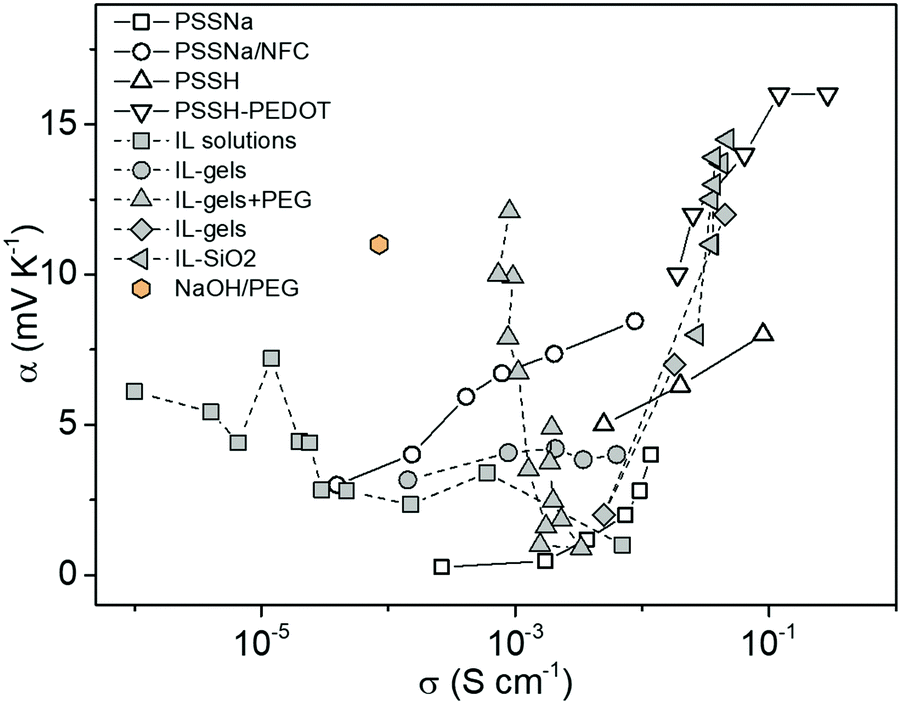 | ||
| Fig. 1 The distribution of the ionic Seebeck coefficient and conductivity of recently reported electrolytes as thermoelectric materials.26–28 | ||
In this work, we aim to probe the pure ionic thermodiffusion and investigate key factors that determine the ionic Seebeck coefficient. We chose a polymer electrolyte without added water in a sealed vertical chamber to reduce the effect of water absorption and evaporation. We use electrodes without fixed ionic charged to avoid any Donnan exclusion effect. The selected electrolytes NaOH dissolved in liquid polyethylene glycol (PEG) acting as a solvent. The dissolution and condensation reaction to produce negatively charged alkoxide polymer was analyzed by NMR. Their composition is tuned to modulate the ionic conductivity and Seebeck coefficient. Methodically, we characterize the viscosity, the molar conductivity and the relevant modes of vibrations by FTIR spectroscopy to reveal the significance of the ion/solvent interaction.
2. Results
2.1. Ionic Seebeck coefficient of the gel electrolytes
The structure of the thermoelectric devices used in this study is illustrated in Fig. 2a. Two Au electrodes (area = 0.8 cm2) separated by a PDMS spacer (1 mm separation) constitute the volume filled by the electrolyte. During measurement, the substrates of the two electrodes are kept in contact with Peltier elements of independently controlled temperature. The compositions of the electrolytes are presented in the inset of Fig. 2b. Glycerol and liquid polyethylene glycol (PEG) of different molecular weight (Mw) are used as solvents, and sodium hydroxide (NaOH) or sodium thiocyanate (NaSCN) are used as the salts to provide mobile ions. The difference in the molecular weight and structure of the solvents provides a gradual variation of the alcohol (PEG–OH) groups in the electrolytes since those groups are located at the end of the PEG chains. As shown in Fig. 2b, for the same weight percentage (3 wt%) of the salts, the molar concentration ratio between the salt and the end alcohol groups increases from glycerol to short chain PEG (PEG200), and to long chain PEG (PEG600). In addition, the electrolyte that contains NaSCN (because of its good solubility in PEGs) and PEG (PEG300) provides a benchmark to detect if the nature of the anions is important.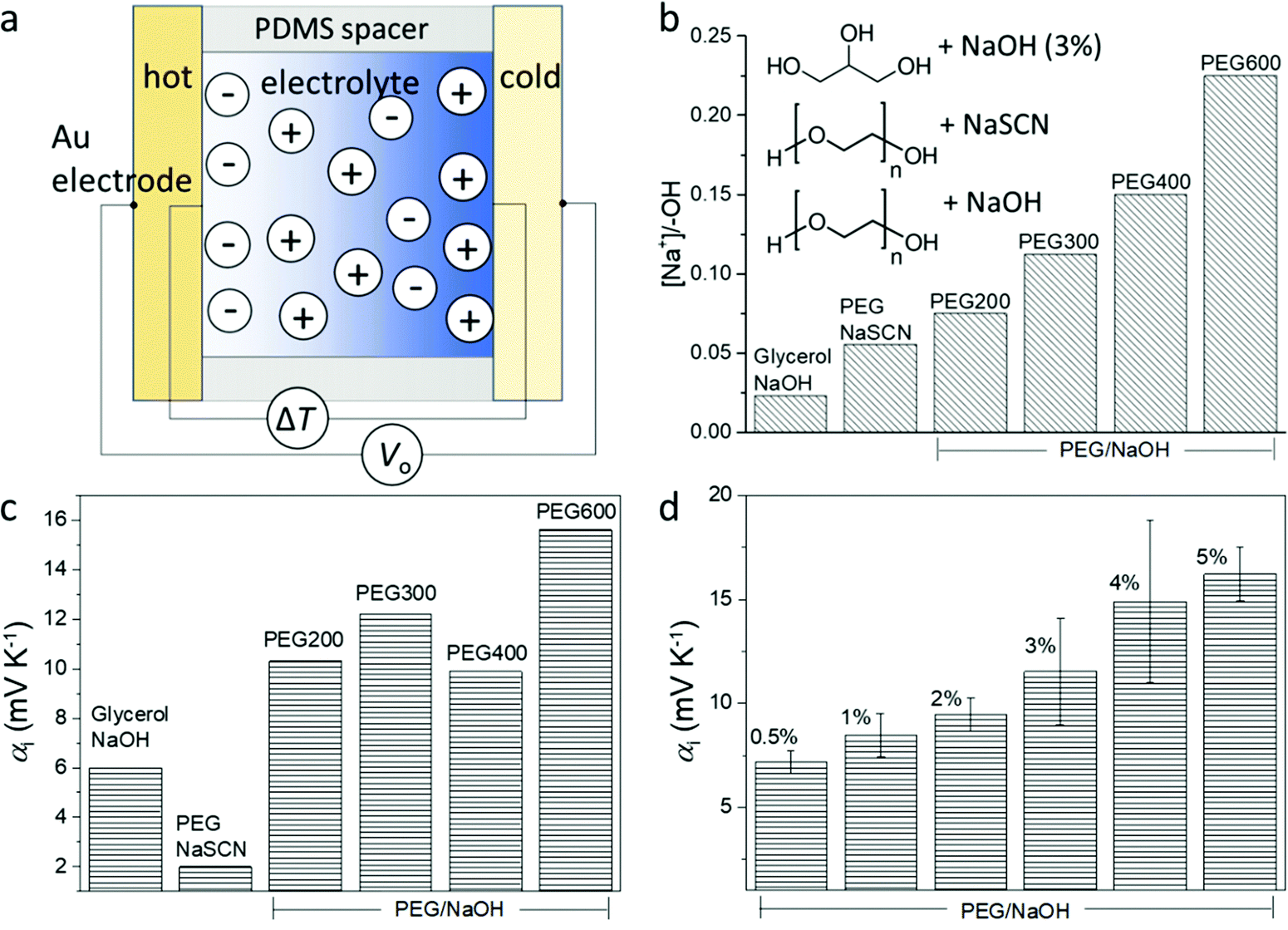 | ||
| Fig. 2 Illustration of the ionic thermoelectric device and involved materials. (a) The structure of the ionic thermoelectric device. (b) The composition of the studied electrolytes with 3 wt% of salts. (c) The Seebeck coefficient of electrolytes containing different salts (3 wt%) and solvents. (d) The Seebeck coefficient of NaOH/PEG(400) electrolytes of different NaOH concentration. | ||
The peculiar role of the hydroxide anion OH− is that they can react with the alcohol end groups −OH of the PEG or glycerol to form an alkoxide –O−Na+ (R–OH + NaOH → R–O−Na+ + H2O),7 which is expected to greatly modify the diffusion of the ions. Understanding that the interaction between the ions and the solvent molecule/polymer is an important effect for the magnitude of the ionic Seebeck coefficient, we suspect that changing the ratio between the concentration of salt and the –OH groups of the solvent could be a way to control the Seebeck coefficient. Small polymer chains offer a higher concentration of –OH end groups compared to long chains for the same weight of solute concentration (3 wt%); hence molecular weight is also expected to be another way to tune the Seebeck coefficient. The Seebeck coefficient (αi) measured for different solvents and salts is presented in Fig. 2c (the measurement details and the linear dependence of the thermal voltage on the temperature difference is shown in Fig. S1, ESI†). The sample containing 3 wt% NaSCN in PEG has a much smaller Seebeck coefficient (∼2 mV K−1) than the electrolyte with NaOH (∼10 mV K−1), which is intuitively expected by the fact that the SCN− anion is mobile and does not react with the end R–OH groups of the PEG; while the OH− anion can undergo the reaction to produce alkoxide. Interestingly, increasing to 6 wt% NaSCN did not much change the ionic Seebeck coefficient. Also even though the trend is not crystal clear, there seems to be an increase in the ionic Seebeck coefficient with the increasing ratio of the amount of solute and the –OH end group from 0.023 to 0.225 (Fig. 2c). Different amounts of NaOH were dissolved in PEG400 to form solutions varying from 0.5 wt% to 5 wt%. As shown in Fig. 2d, a higher amount of NaOH leads to an increasing Seebeck coefficient from +7 mV K−1 (0.5 wt%) to +16 mV K−1 (5 wt%).
2.2. Spectroscopic insight into ion–polymer solvent interactions
To probe the different ion/solvent interactions between the investigated electrolytes that could result in their different Seebeck coefficients, we compared the characteristic adsorption peak in Fourier transform infrared spectroscopy (FTIR) of the solvents (PEGs and glycerol) and the formed electrolytes. Fig. 3a shows the typical O–H stretching adsorption (between 3200 to 3600 cm−1)32 of the electrolytes containing 3 wt% of NaOH in different PEGs. We observed that the peaks at 3400–3450 cm−1 became weaker and a new peak at 3200 cm−1 started to appear after NaOH was added. As illustrated in Fig. 3b, this can be identified as the substitution of the proton of R–OH by Na+ cation through the formation of alkoxide groups R–O−Na+ taking place upon condensation of water. The formation of –ONa is also proved by the H1-NMR measurement. As shown in Fig. S2a, (ESI†) the addition of NaOH leads to a dramatic decreasing of the proton signal from the –OH end groups at 4.5 ppm,33 indicating that 95% of the proton from the –OH end group was removed. However, as shown in Fig. 2b, the concentration ratio between the added NaOH and –OH end group of PEGs is between 0.075 to 0.225, which is far below 95%. According to previous literature, this could be due to the condensation of two PEG molecule into a longer chain catalyzed by the alkoxide –ONa.34 The formation of longer PEG and bonding with Na+ cation could be one contribution to the increased viscosity of the electrolytes after adding NaOH35 (shown in Fig. S4, ESI†). Moreover, the H1-NMR characteristic downfield peak of the remaining proton from –OH groups shift from 4.54 ppm in pure PEG–OH to 4.92 (Fig. S2a, ESI†), which indicates the formation of a stronger H-bond after adding NaOH to PEG.36 There are two possible explanations for that shift. Firstly, the residual water produced by the condensation acts as a cross-linker via H-bonds interacting with the oxygen of the ether groups of adjacent PEG chains; and secondly, the OH− anions are able to provide higher electron density on the proton of the –OH groups of PEG than neutral hydroxyl groups.37 These hypotheses are in agreement with the FTIR spectra displaying an increasing background at lower wavenumber (∼3200 cm−1) (Fig. S3a, ESI†) and the increasing characteristic peak from H2O (Fig. S3b, ESI†) with the increasing NaOH content in PEG400. However, more experiments will be needed to confirm these hypotheses. Similarly, in Fig. 3a, the magnitude of the change increases with the higher Mw of PEG, due to the increasing ratio between the NaOH and –OH concentration.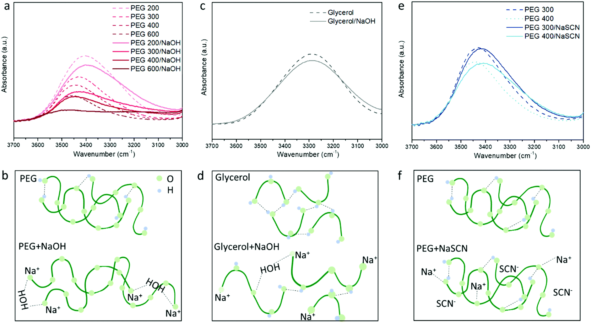 | ||
| Fig. 3 The FTIR characterization of different electrolytes in room temperature. (a) The O–H stretching peak and (b) illustration of PEG/NaOH electrolytes. (c) The OH stretching peak and (d) illustration of the glycerol/NaOH electrolyte. (e) The OH stretching peak and (f) illustration of the PEG/NaSCN electrolyte. | ||
For the glycerol solution, the O–H peak at 3400 cm−1 also slightly reduced and the peak at the low frequency region appears after adding NaOH similar to the PEG200 (Fig. 3c). Combined with the NMR results shown in Fig. S2b, (ESI†) this can be attributed to the similar effect of Na+ substitution of the proton of the –OH end groups as in NaOH/PEGs electrolytes. However, different from the large shift in the H1-NMR peak of the proton from the remaining –OH groups in NaOH/PEG solution (from 4.5 ppm to 4.9 ppm), the same shift in NaOH/glycerol is only from 4.5 ppm to 4.6 ppm. This could be due to the large number of –OH groups in glycerol compared to PEGs, that still remain unreacted with NaOH (as illustrated in Fig. 3d). In NaSCN/PEG electrolyte, the intensity of the FITR peak of the O–H bond from PEG does not decrease (Fig. 3e) and no shift in H1-NMR of the same proton (Fig. S2a, ESI†) was observed, indicating that NaSCN does not react with PEG as NaOH. Note that adding NaSCN still increases the viscosity of the electrolyte compared to PEG solvent due to the coordination bond between the O from PEG and Na+![[thin space (1/6-em)]](https://www.rsc.org/images/entities/char_2009.gif) 35 (Fig. 3f).
35 (Fig. 3f).
2.3. Trends in the molar ionic conductivity
The different interactions that the ions experience in a solvent usually affect the ionic conductivity of the electrolytes.38 Hence, we used the frequency-dependent impedance and the corresponding equivalent circuit to obtain the total ionic conductivity of the electrolytes, as shown in Fig. S5 (ESI†). The ionic conductivity depends on the concentration and the diffusion coefficient of the ions. In order to remove the contribution of concentration, the molar conductivity of the electrolytes is calculated and shown in Fig. 4. From the reaction implied by the NMR and FTIR results, the OH− anion in PEG and glycerol electrolyte is likely to be consumed. Hence, we expected the cation to be the major charge carrier in the formed electrolytes. This is in agreement with the measured positive Seebeck coefficient. From the results of NaOH in different PEGs and glycerol in Fig. 4a, the electrolytes with high Mw have smaller molar conductivity compared to the shorter PEGs, due to the slow segmental movement of the polymers.38 But more surprising is that the molar conductivity (related to the ionic mobility) decreased with increasing NaOH concentration (Fig. 4b). We associate that with the resulting increase in viscosity of the electrolyte through ion/solvent interactions, or cross-coupling of PEG chains or water acting as the H-bond type cross-linker. To summarize the conductivity of different electrolytes, the molar conductivity is plotted with their viscosity (η) in a so-called Walden plot (Fig. 4c). The viscosity of different electrolytes is shown in Fig. S4 (ESI†) with the comparison with the solvent. The electrolytes of NaOH and NaSCN in PEG follow the (fractional) Einstein–Stoke relation, in which the molar conductivity of the ions is reversely proportional to the viscosity.39 The only exception is the glycerol/NaOH with a much higher viscosity than the rest of the electrolytes possibly due to the high density of H-bonds in that solvent but also of the higher diffusion coefficient of the molecular solvent compared to the PEG solvent.38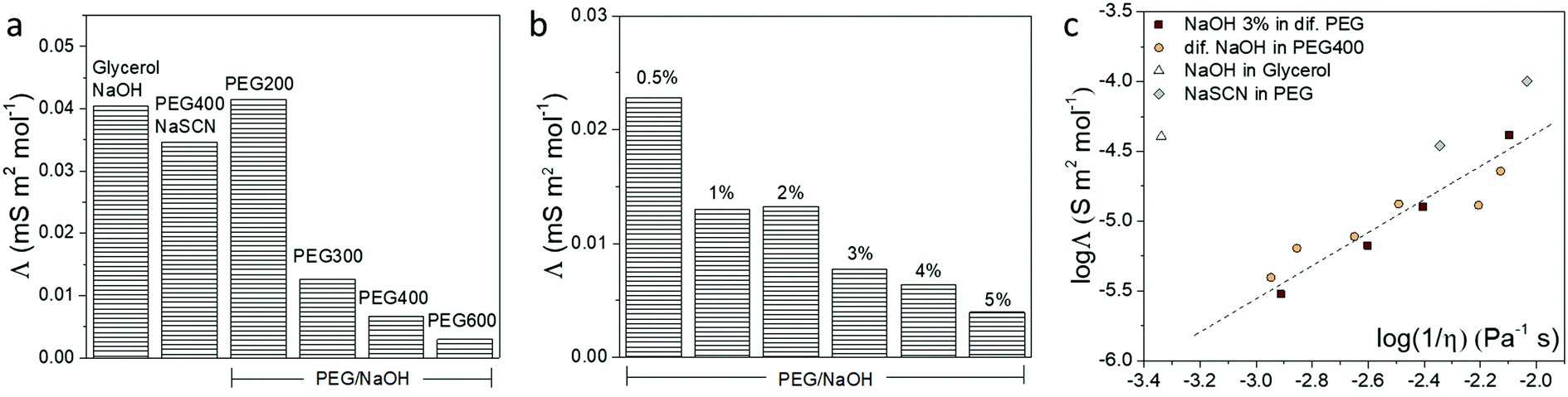 | ||
| Fig. 4 The molar conductivity of different electrolytes. (a) The molar conductivity of electrolytes with the same molar concentration of NaOH or NaSCN in PEGs and glycerol. (b) The molar conductivity of electrolytes containing different percentage of NaOH in PEG400. (c) The molar conductivity of all the electrolytes versus their reversed viscosity. | ||
There are two extreme mechanisms describing the transport of ions in electrolytes. Firstly, the ions with its solvation shell are seen as migrating progressively and experiencing a friction force related to the viscosity of the solvent. The Einstein–Stokes relationship between the molar conductivity and the viscosity has been used in diluted salt solution with molecular solvents, which are systems where the diffusion coefficient of simple ions is smaller than, or equal to, that of solvent molecules.40 Secondly, the ions are hopping from site to site in the solid electrolyte.41 Thus not at all depending on the macroscopic viscosity of the polymer but through the local dynamics of the polymer chains described by a relaxation time. This is the case of a salt dispersed in high molecular weight PEG in the solid state.42 The systems studied in this work are in-between two extreme cases since the PEG constitutes a polymeric liquid solvent. That is why we can still observe a dependence between the molar conductivity and the macroscopic viscosity. This means that the local chain dynamics is still related to the macroscopic viscosity, and the ions form a partial solvation shell and diffuse by hopping from site to site, such that the activation energy of the hopping is actually related to the macroscopic viscosity. This explains the trend observed in Fig. 4c.
2.4. Interplay between molar conductivity and ionic Seebeck coefficient
From discussing the different interactions between the ions and the solvent, we found out that the OH−/–OH interaction and reaction plays a key role for the ion transport and Seebeck coefficient. As shown in Fig. 5a, the molar conductivity of electrolytes has a clear trend with the ratio between the concentration of the solute OH− anions and the –OH end group from the solvent, which determines the magnitude of the ion/solvent interaction. Thanks to the tunable ion/solvent interaction in the series of electrolytes of analogous compositions, we could summarize their Seebeck coefficient versus molar conductivity. As shown in Fig. 5b, the Seebeck coefficient increases with decreasing molar conductivity. This observation could be explained by the recently reported thermoelectric ratchet effect for ions with hopping transport dynamics.25 | ||
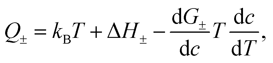
Fig. 5 A summary of the molar conductivity and Seebeck coefficient. (a) The molar conductivity of the electrolytes versus the ratio between the anion and –OH end group concentration. (b) The Seebeck coefficient of the electrolytes versus the molar conductivity. (c) Free enthalpy landscape of a mobile ion, with the barrier ΔH between nearby minima and a temperature gradient in the negative x-direction, 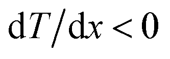 . (i) Because of the exponential factor of the rate Γ = Γ0e−ΔH/kBT+ΔS/kB, jumps from the left to the right, i.e. from the hot to the cold, occur more frequently than those in the opposite direction. As a consequence, there is a thermodiffusion current toward the cold which gives rise to a Seebeck coefficient with the heat of transport (3). Since the entropy of activation ΔS does not contribute to this effect, we show the enthalpy barrier only. (ii) In addition to the periodic variation, the free enthalpy G at the bottom of the wells varies smoothly along the temperature gradient, as indicated by the dashed line, enhancing thermodiffusion and the Seebeck effect, according to the second term in the heat of transport (4). (iii) In general, both the enthalpy at the bottom of the wells G and the barrier ΔH depend on temperature, and here we show the case where G decreases and ΔH increases at lower temperature. Note that the variation of ΔH does not affect the direction of thermodiffusion. . (i) Because of the exponential factor of the rate Γ = Γ0e−ΔH/kBT+ΔS/kB, jumps from the left to the right, i.e. from the hot to the cold, occur more frequently than those in the opposite direction. As a consequence, there is a thermodiffusion current toward the cold which gives rise to a Seebeck coefficient with the heat of transport (3). Since the entropy of activation ΔS does not contribute to this effect, we show the enthalpy barrier only. (ii) In addition to the periodic variation, the free enthalpy G at the bottom of the wells varies smoothly along the temperature gradient, as indicated by the dashed line, enhancing thermodiffusion and the Seebeck effect, according to the second term in the heat of transport (4). (iii) In general, both the enthalpy at the bottom of the wells G and the barrier ΔH depend on temperature, and here we show the case where G decreases and ΔH increases at lower temperature. Note that the variation of ΔH does not affect the direction of thermodiffusion. | ||
The molar conductivity of the studied electrolytes shows activated behavior (see Fig. S5, ESI† and ref. 14), indicating that the carriers move through jumps between nearby sites. Then the molar conductivity reads as:
| Λ = Λ0e−ΔG/kBT, | (3) |
| Q± = kBT + ΔH±, | (4) |
Eqn (3) and (4) imply a linear relation between the Seebeck coefficient and the logarithm of the molar conductivity (α ∝ lnΛ). The experimental data in Fig. 5b confirm this correlation, suggesting that hopping dynamics is indeed relevant for ionic thermodiffusion of the studied electrolytes. At first sight it is tempting to relate this dependence to the viscosity, which shows the same activated behavior (Fig. 4c). Yet the Seebeck coefficient is given by the ratio of two transport coefficients, which describe the thermodiffusion and electric-field driven transport, and which are proportional to the ionic mobility. Thus, in hydrodynamic theories for thermoelectric effects, both are inversely proportional to the viscosity, such that the Seebeck coefficient is not.43 In the hopping model discussed here, these transport coefficients are proportional to the jump rate Γ = Γ0e−ΔG/kBT between neighbor wells, whereas the exponential factor disappears in the Seebeck coefficient.25 In the simplest case of a single carrier species, eqn (2) arises from α = kBTdlnΛ/dT, which reminds us of early work on the Seebeck effect of metals.44
A quantitative comparison shown in Table 1, however, reveals that the heat of transport calculated from our Seebeck data according to eqn (2), is significantly larger than the activation enthalpy. For example, from Fig. S6 (ESI†) we obtain the activation enthalpy ΔH = 0.271 eV for PEG containing 0.5% and ΔH = 0.451 eV for the sample with 5% NaOH, whereas from the thermoelectric data we find for the weighted heat of transport Q = w+Q+ − w−Q− the values Q = 2.1 eV and 4.9 eV. Although the data show the same trend – both ΔH and Q increase with the salt content – their absolute values differ by roughly a factor of ten. In the framework of the hopping model, there are several possible origins for this discrepancy. First, sodium and hydroxide ions could show very different activation enthalpies, ΔH+ ≫ ΔH−, such that ΔH+ determines the heat of transport Q. Because of the large barrier, the cations would contribute little to the conductivity, and the exponential factor in (3) would be given by ΔH−. Different from NaOH/PEG, the activation enthalpy of NaSCN/PEG obtained from Fig. S6 (ESI†) is 0.374 eV, which is close to the value calculated from the Seebeck coefficient data (0.58 eV). This could be due to the relatively similar interaction with the solvent of both anions and cations. Second the discrepancy between the heat of transport and enthalpy of activation could arise from a temperature dependent “companion field” c, resulting in the effective heat of transport:25
 | (5) |
| NaOH 0.5% | NaOH 5% | NaSCN | |
|---|---|---|---|
| ΔH (eV) | 0.271 | 0.451 | 0.374 |
| α (mV K−1) | 6.3 | 15 | 2 |
| Q (eV) | 2.1 | 4.9 | 0.58 |
In ref. 25 the effective heat of transport (5) was discussed with c the weight fraction of a molecular component. For example, the free enthalpy barrier in polyelectrolyte complexes strongly decreases with the water content,45 whereas it increases in EM the ionic liquid EMIM-Oac upon adding sugar.46 In the present system, however, there is no other component beyond PEG and NaOH. In principle the weight fraction of NaOH could play the role of the companion field c. The above concentration dependence of conductivity and Seebeck data, could be met by assuming free-enthalpy derivatives for cations and anions dG+/dc ≈ −dG−/dc, such that these terms would significantly contribute to the Seebeck coefficient α ∝ d(G+ − G−)/dc, yet be almost absent in the salt Soret coefficient ST ∝ d(G+ + G−)/dc. At present there are no thermodynamic or spectroscopy data supporting this assumption.
As another example of a companion field we mention the permittivity ε. Ion–ion interactions and hydrogen bonding depend strongly on ε. On the other hand, the permittivity of PEG varies with temperature according to dε/dT ≈ −3ε/T.47 The electrostatic interaction energy of two nearby ions in PEG, e2/4πεd ∼ 0.2 eV, thus contributes to the heat of transport (5) a term of the order of 1 eV, which is not far from the experimental values of 2.1 eV and 4.9 eV. As another interesting aspect in view of the data of Fig. 4a, we note that the permittivity of PEG varies significantly with the molecular weight, for PEG200 it is twice that of PEG600.47 Unfortunately, there seems to be no thermodynamic data on the system PEG–NaOH, and in particular on varying concentration, which would allow a more thorough comparison.
Finally, as a third possible mechanism, we note that the weight factors w± = n±/(n+ + n−) appearing in the expression for the Seebeck coefficient (2), need not be identical. Though the system needs to satisfy charge neutrality, this is not necessarily the case for the mobile ion fractions. For ionic liquids it is known that the concentrations n± of mobile ions may differ significantly due to ion aggregation. For example, for EMIN-TSFI, the transport numbers t± differ by a factor of ten,48 resulting in an even larger concentration ratio of mobile carriers.
3. Conclusion
In this work, we have systematically studied the underlying mechanism for the large Seebeck coefficient in non-aqueous electrolytes excluding the impact of water evaporation. The molar conductivity, viscosity and Seebeck coefficient of electrolytes containing series of PEG and glycerol with NaOH and NaSCN as the salts, were investigated and compared. The different ion/solvent interactions are characterized by FTIR and NMR spectroscopy and identified as the main reason for the different Seebeck coefficient of the electrolytes. Benefiting from the variation in molar conductivity among analogy electrolytes of NaOH in PEGs, we are able to reveal the linear correlation between the Seebeck coefficient and logarithm of the molar conductivity of the ions. The correlation agrees remarkably well with a previous theoretical description of the thermoelectric ratchet effect in ionic conductors with hopping transport dynamics. Our work has extended the understanding of the underlying mechanism of ionic thermoelectric effect in complex electrolytes and will provide guidelines for the development of this field.4. Experimental section
Device fabrication
All the chemicals (glycerol, liquid polyethylene glycol (PEG) of different molecular weight (Mw), sodium hydroxide (NaOH) and sodium thiocyanate (NaSCN)) were purchased from Sigma Aldrich and used as received. Glass wafers were ultrasonicated in soap water followed by deionized (DI) water for 5 min each. They were rinsed with DI water, acetone and isopropanol and dried by blowing N2 stream, then baked at 130 °C in an oven for 30 min. Plastic shadow masks were used to evaporate 5 nm Cr and 30 nm Au electrodes on the clean glass. Both the prepared glass substrate and PDMS (1 mm thickness) are exposed in UV plasma for 3 min, then contacted and baked at 70 °C in an oven for 10 min, then a cavity of 0.0785 cm3 is obtained.To prepare the polymeric electrolytes, PEG or glycerol was mixed with certain amounts of NaOH or NaSCN, and the mixtures were heated to 70 °C on a hotplate for 2 hours until the salt completely dissolved. The electrolyte was then injected into the chamber with Au electrodes on both sides.
Characterization
The impedance measurements were carried out using an impedance spectrometer (Alpha high-resolution dielectric analyzer, Novocontrol Technologies GmbH, Hundsangen, Germany). An AC voltage of 10 mV was applied while sweeping the frequency.The thermoelectric measurements were performed in a home-built setup. The temperature was controlled by two Peltier elements via a Labview program, and the temperature difference between two electrodes was monitored using a thermocouple simultaneously. The open-circuit voltage generated by the devices was measured using a Keithley 2182A nanovoltmeter set to auto-range. The temperature cycles were applied through a Labview program. Open-circuit voltage measurements throughout this work were done under cleanroom humidity of 38% to 40% unless otherwise stated.
Proton nuclear magnetic resonance 1H spectra were recorded on a Brucker (500 MHz) spectrometer. The deuterated solvent was used as an internal standard for DMSO-d6 (1H, δ = 2.50) and used as a reference. All the samples were analyzed using 15% (w/w) solution of the sample in DMSO-d6.
Fourier transform infrared spectroscopy (FTIR) was carried out in Attenuated total reflectance mode (ATR) (Bruker, Equinox 55) by dropping the liquid electrolytes on the ATR crystal.
Conflicts of interest
There are no conflicts to declare.Acknowledgements
The authors thank the Knut and Alice Wallenberg Foundation (proof of concept “Hi-VAE”), Swedish Research Council (VR 2016-05990, 2016-06146 and 2018-04037), and Advanced Functional Materials Center at Linköping University (2009-00971).References
- G. J. Snyder and E. S. Toberer, Nat. Mater., 2008, 7, 105–114 CrossRef CAS PubMed.
- H. Xi, L. Luo and G. Fraisse, Renewable Sustainable Energy Rev., 2007, 11, 923–936 CrossRef CAS.
- L. E. Bell, Science, 2008, 321, 1457–1461 CrossRef CAS PubMed.
- A. Nozariasbmarz, F. Suarez, J. H. Dycus, M. J. Cabral, J. M. LeBeau, M. C. Öztürk and D. Vashaee, Nano Energy, 2020, 67, 104265 CrossRef CAS.
- R. C. O’Brien, R. M. Ambrosi, N. P. Bannister, S. D. Howe and H. V. Atkinson, J. Nucl. Mater., 2008, 377, 506–521 CrossRef.
- D. Champier, Energy Convers. Manag., 2017, 140, 167–181 CrossRef.
- D. Zhao, H. Wang, Z. U. Khan, C. Chen, R. Gabrielsson, M. P. Jonsson, M. Berggren and X. Crispin, Energy Environ. Sci., 2016, 9, 1450 RSC.
- S. L. Kim, H. T. Lin and C. Yu, Adv. Energy Mater., 2016, 6, 1600546 CrossRef.
- H. Wang, D. Zhao, Z. U. Khan, S. Puzinas, M. P. Jonsson, M. Berggren and X. Crispin, Adv. Electron. Mater., 2017, 3, 1700013 CrossRef.
- N. S. Hudak and G. G. Amatucci, J. Electrochem. Soc., 2001, 158, 572–579 CrossRef.
- W. Kobayashi, A. Kinoshita and Y. Moritomo, App. Phys. Lett., 2015, 107, 073906 CrossRef.
- X. Guan, H. Cheng and J. Ouyang, J. Mater. Chem. A, 2018, 6, 19347–19352 RSC.
- H. Cheng, X. He, Z. Fan and J. Ouyang, Adv. Energy Mater., 2019, 9, 1901085 CrossRef.
- X. He, H. Cheng, S. Yue and J. Ouyang, J. Mater. Chem. A, 2020, 8, 10813–10821 RSC.
- T. Li, X. Zhang, S. D. Lacey, R. Mi, X. Zhao, F. Jiang, J. Song, Z. Liu, G. Chen, J. Dai, Y. Yao, S. Das, R. Yang, R. M. Briber and L. Hu, Nat. Mater., 2019, 18, 608–613 CrossRef CAS PubMed.
- C. Cho, K. L. Wallace, P. Tzeng, J.-H. Hsu, C. Yu and J. C. Grunlan, Adv. Energy Mater., 2016, 6, 1502168 CrossRef.
- D. Zhao, A. Martinelli, A. Willfahrt, T. Fischer, D. Bernin, Z. U. Khan, M. Shahi, J. Brill, M. P. Jonsson, S. Fabiano and X. Crispin, Nat. Commun., 2019, 10, 1093 CrossRef PubMed.
- D. Zhao, S. Fabiano, M. Berggren and X. Crispin, Nat. Commun., 2017, 8, 14214 CrossRef CAS PubMed.
- Z. A. Akbar, J.-W. Jeon and S.-Y. Jang, Energy Environ. Sci., 2020, 13, 2915–2923 RSC.
- E. D. Eastman, J. Am. Chem. Soc., 1926, 48, 1482–1493 CrossRef CAS.
- A. Würger, Phys. Rev. Res., 2020, 2, 042030 CrossRef.
- M. Bonetti, S. Nakamae, M. Roger and P. Guenoun, J. Chem. Phys., 2011, 134, 114513 CrossRef CAS PubMed.
- B. Russ, A. Glaudell, J. J. Urban, M. L. Chabinyc and R. A. Segalman, Nat. Rev. Mater., 2016, 1, 16050 CrossRef CAS.
- Q. L. Jiang, H. D. Sun, D. K. Zhao, F. L. Zhang, D. H. Hu, F. Jiao, L. Q. Qin, V. Linseis, S. Fabiano, X. Crispin, Y. G. Ma and Y. Cao, Adv. Mater., 2020, 32, 2002752 CrossRef CAS PubMed.
- A. Würger, Phys. Rev. Lett., 2021, 126, 068001 CrossRef PubMed.
- M. Bonetti, S. Nakamae, M. Roger and P. Guenoun, J. Chem. Phys., 2011, 134, 114513 CrossRef CAS PubMed.
- B. Russ, A. Glaudell, J. J. Urban, M. L. Chabinyc and R. A. Segalman, Nat. Rev. Mater., 2016, 1, 16050 CrossRef CAS.
- F. Jiao, A. Naderi, D. Zhao, J. Schlueter, M. Shahi, J. Sundström, H. Granberg, J. Edberg, U. Ail, J. Brill, T. Lindström, M. Berggren and X. Crispin, J. Mater. Chem. A, 2017, 5, 16883–16888 RSC.
- S. L. Kim, J. H. Hsu and C. Yu, Org. Electron., 2018, 54, 231–236 CrossRef CAS.
- D. Zhao, A. Sultana, J. Edberg, M. Shiran Chaharsoughi, M. Elmahmoudy, U. Ail, K. Tybrandt and X. Crispin, J. Mater. Chem. C, 2022, 10, 2732–2741 RSC.
- S. Mardi, D. Zhao, N. Kim, I. Petsagkourakis, K. Tybrandt, A. Reale and X. Crispin, Adv. Electron. Mater., 2021, 210056 Search PubMed.
- J. M. Dust, A. H. Fang and J. M. Harris, Macromolecules, 1990, 23, 3742–3746 CrossRef CAS.
- E. E. Reid, H. Worthington and A. Larchar, J. Am. Chem. Soc., 1939, 61, 99–101 CrossRef CAS.
- W. Qian and S. Krimm, J. Phys. Chem. A, 2002, 106, 6628–6636 CrossRef CAS.
- H. F. Abbasov, J. Polym. Res., 2017, 24, 115 CrossRef.
- P. Kolhe and R. M. Kannan, Biomacromolecules, 2003, 4(1), 173–180 CrossRef CAS PubMed.
- M. C. Ali, R. Liu, J. Chen, T. Cai, H. Zhang, Z. Li, H. Zhai and H. Qiu, Chin. Chem. Lett., 2019, 30, 871–874 CrossRef CAS.
- M. S. Mendolia and G. C. Farrington, Chem. Mater., 1993, 5, 174–181 CrossRef CAS.
- P. Walden, Z. Phys. Chem., 1906, 55, 207 CrossRef CAS.
- C. Schreiner, S. Zugmann, R. Hartl and H. J. Gores, Chem. Eng. Data, 2010, 55, 1784–1788 CrossRef CAS.
- D. Bresser, S. Lyonnard, C. Iojoiu, L. Picard and S. Passerini, Mol. Syst. Des. Eng., 2019, 4, 779–792 RSC.
- D. Golodnitsky, E. Strauss, E. Peled and S. Greenbaum, J. Electrochem. Soc., 2015, 162, A2551 CrossRef CAS.
- J. N. Agar, C. Y. Mou and J.-L. Lin, J. Phys. Chem., 1989, 93, 2079–2082 CrossRef CAS.
- H. Fritzsche, Solid State Commun., 1971, 9, 1813–1815 CrossRef CAS.
- S. De, A. Ostendorf, M. Schönhoff and C. Cramer, Polymers, 2017, 9, 550 CrossRef PubMed.
- C. D'Agostino, M. D. Mantle, C. L. Mullan, C. Hardacre and L. F. Gladden, ChemPhysChem, 2018, 19, 1081–1088 CrossRef PubMed.
- A. V. Sarode and A. C. Kumbharkhane, J. Mol. Liq., 2011, 164, 226–232 CrossRef CAS.
- J. P. Tafur, F. Santos and A. J. F. Romero, Membranes, 2015, 5, 752 CrossRef CAS PubMed.
Footnote |
| † Electronic supplementary information (ESI) available. See DOI: https://doi.org/10.1039/d2tc01130a |
| This journal is © The Royal Society of Chemistry 2022 |