
 Open Access Article
 This Open Access Article is licensed under a
 Creative Commons Attribution 3.0 Unported Licence
Fluorinated dibenzo[a,c]-phenazine-based green to red thermally activated delayed fluorescent OLED emitters†
Gloria
Hong‡
 a,
Changfeng
Si‡
b,
Abhishek Kumar
Gupta‡
bc,
Claudia
Bizzarri
a,
Martin
Nieger
d,
Ifor D. W.
Samuel
*c,
Eli
Zysman-Colman
*b and
Stefan
Bräse
*ae
a,
Changfeng
Si‡
b,
Abhishek Kumar
Gupta‡
bc,
Claudia
Bizzarri
a,
Martin
Nieger
d,
Ifor D. W.
Samuel
*c,
Eli
Zysman-Colman
*b and
Stefan
Bräse
*ae
aInstitute of Organic Chemistry, Karlsruhe Institute of Technology (KIT), Fritz-Haber-Weg 6, 76131 Karlsruhe, Germany. E-mail: stefan.braese@kit.edu
bOrganic Semiconductor Centre, EaStCHEM School of Chemistry, University of St Andrews, St Andrews, Fife, KY16 9ST, UK. E-mail: eli.zysman-colman@st-andrews.ac.uk; Fax: +44 (0)1334 463808; Tel: +44 (0)1334 463826
cOrganic Semiconductor Centre, SUPA School of Physics and Astronomy, University of St Andrews, St Andrews, Fife, KY16 9SS, UK. E-mail: idws@st-andrews.ac.uk; Fax: +44 (0)1334 463104; Tel: +44 (0)1334 463826
dDepartment of Chemistry, University of Helsinki, P. O. Box 55, 00014, Finland
eInstitute of Biological and Chemical Systems (IBCS-FMS), Karlsruhe Institute of Technology (KIT), Hermann-von-Helmholtz-Platz 1, 76344 Eggenstein-Leopoldshafen, Germany
First published on 10th December 2021
Abstract
Purely organic thermally activated delayed fluorescence (TADF) emitting materials for organic light-emitting diodes (OLEDs) enable a facile method to modulate the emission color through judicious choice of donor and acceptor units. Amongst purely organic TADF emitters, the development of TADF molecules that emit at longer wavelengths and produce high-efficiency devices that show low efficiency roll-off remains a challenge. We report a modular synthesis route that delivers three structurally related fluorinated dibenzo[a,c]-phenazine-based TADF molecules, each bearing two donor moieties with different electron-donating strengths, namely 3,6-bis(3,6-di-tert-butyl-9H-carbazol-9-yl)-10-fluorodibenzo[a,c]phenazine (2DTCz-BP-F), 3,6-bis(9,9-dimethylacridin-10(9H)-yl)-10-fluorodibenzo[a,c]phenazine (2DMAC-BP-F) and 10,10'-(10-fluorodibenzo[a,c]phenazine-3,6-diyl)bis(10H-phenoxazine) (2PXZ-BP-F). They exhibit donor strength-controlled color-tuning over a wide color range from green to deep-red with photoluminescence maxima, λPL, of 505 nm, 589 nm, and 674 nm in toluene solution. OLED devices using these TADF materials showed excellent to moderate performance with an EQEmax of 21.8% in the case of 2DMAC-BP-F, 12.4% for 2PXZ-BP-F and 2.1% with 2DTCZ-BP-F, and associated electroluminescence (EL) emission maxima, λEL, of 585 nm, 605 nm and 518 nm in an mCBP host, respectively.
Introduction
Among the emitting materials for use in organic light-emitting diodes (OLEDs), purely organic thermally activated delayed fluorescence (TADF) emitters have drawn intense interest in recent years as they enable devices to reach a theoretical internal quantum efficiency (IQE) of 100%. This is possible through efficient harvesting of both singlet and triplet excitons to produce light, the latter of which are converted to the former via reverse intersystem crossing (RISC). Organic TADF emitters do not contain scarce, noble metals that are extracted through environmentally damaging mining operations. Swift progress has been reported in the development of purely organic TADF emitters and now there are numerous examples of TADF OLEDs showing comparable efficiencies to phosphorescent devices.1,2RISC at ambient temperatures occurs in organic compounds that possess a small energy gap, ΔEST, between the lowest-lying singlet state S1 and triplet state T1, and show non-zero spin–orbit coupling (SOC).3 For this scenario to occur, there must be a spatial separation of the electron-donating unit accommodating the highest-occupied molecular orbital (HOMO) and the electron-accepting unit hosting the lowest-unoccupied molecular orbital (LUMO).4 The implementation of this donor–acceptor molecular design produces a strong charge-transfer (CT) character of the S1 state.3
The design of TADF materials that emit at longer wavelengths poses some unique challenges for maintaining a high photoluminescence quantum yield (ΦPL). The ΦPL is dependent on the rate constant of radiative decay processes such as fluorescence, but also nonradiative decay processes such as internal conversion (IC) and intersystem crossing (ISC).5 In large, aromatic molecules, where the electronic relaxation lies within the rule of a weak coupling limit as reported by Englman and Jortner,6 the rate constant of the nonradiative decay, knr, is inversely proportional to the exponential of the optical energy gap ΔEopt. In contrast, the rate constant of the radiative decay, kr, is proportional to the cube of ΔEopt.5,7,8 As the energy of the emissive excited state decreases, the influence of nonradiative decay increases exponentially because the vibronic coupling between the excited state and ground state is facilitated. The challenge of reducing losses due to vibrational quenching and other nonradiative decay pathways in TADF molecules emitting at longer wavelengths can be partially addressed by introducing rigidity into the molecular structure of the donor and acceptor units. Common acceptors for purely organic TADF emitters are aromatic ketones such as anthraquinones, naphthalimides, or heteroaromatic systems like quinoxaline and dibenzo[a,c]phenazine (BP).9 These acceptors show deep LUMO levels of −3.4 eV,10 −2.99 eV,11 −2.81 eV,12 and −2.90 eV,13 respectively, that contribute to stabilizing the S1 state and are therefore beneficial for use in the design of TADF emitters targeting longer wavelength regions.
Zhao and co-workers first reported TADF compounds bearing the BP acceptor, which exhibits a rigid, large π-conjugated system.14 These compounds contain one to three donor moieties in the donor–acceptor or poly(donor)–acceptor strategy, which are commonly applied for TADF molecule design. The greater number of 9,9-dimethyl-9,10-dihydroacridine (DMAC) donors was expected to strengthen the intramolecular charge transfer (ICT) and lead to color-tuning from green to orange-red emission with electroluminescence maxima, λEL, of 560 nm, 576 nm, and 606 nm for devices featuring 1DMAC-BP, 2DMAC-BP, and 3DMAC-BP, respectively (Fig. 1). A maximum external quantum efficiency (EQEmax) of 22.0% was observed for the OLED device with 3DMAC-BP doped in mCBP (18 wt%) at 606 nm. By employing the stronger donor 10H-phenoxazine (PXZ), the λEL for the devices with 1PXZ-BP, 2PXZ-BP, and 3PXZ-BP were red-shifted to 590 nm, 606 nm, and 634 nm, respectively. The most efficient device with 1PXZ-BP as the emitter showed an EQEmax of 26.3% (7 wt% doped in CBP).13 Both Lee and coworkers as well as Wang and coworkers, have reported fluoro-substituted BP acceptors intending to strengthen the acceptor with the presence of the strongly inductively electron-withdrawing fluorine substituent.15,16 Lee and coworkers reported the use of a fluorine substituent at the acceptor moiety in the ortho-position (FBPCNAc, Fig. 1) to the donor moiety. FBPCNAc is brightly luminescent in 1 wt% doped polystyrene film with λPL = 607 nm, a ΦPL of 79% and a delayed lifetime of τd = 11.1 μs. In the electroluminescent (EL) device, it showed an emission maximum of λEL = 597 nm, an EQEmax of 23.8% and low efficiency roll-off. Wang and coworkers on the other hand, attached two fluorine substituents in 11- and 12-position to the BP acceptor on the opposite side of the donor moieties in 3- and 6-position (TAT-FDBPZ, Fig. 1) and observed that the introduction of the fluorine substituents led to a stronger ICT state and a red-shifted emission. The emission of the 20 wt% doped CBP films of the fluorinated TAT-FDBPZ is bathochromically shifted from λPL = 593 nm by 17 nm in comparison to its non-fluorinated analogue (λPL = 576 nm). However, this came at the cost of a slightly decreased ΦPL from 76% to 62%. The τd of TAT-FDBPZ is 1.51 μs, which is shorter than for the non-fluorinated analog where τd = 2.30 μs. The device based on TAT-FDBPZ showed λEL of 611 nm and an EQEmax of 9.2%.
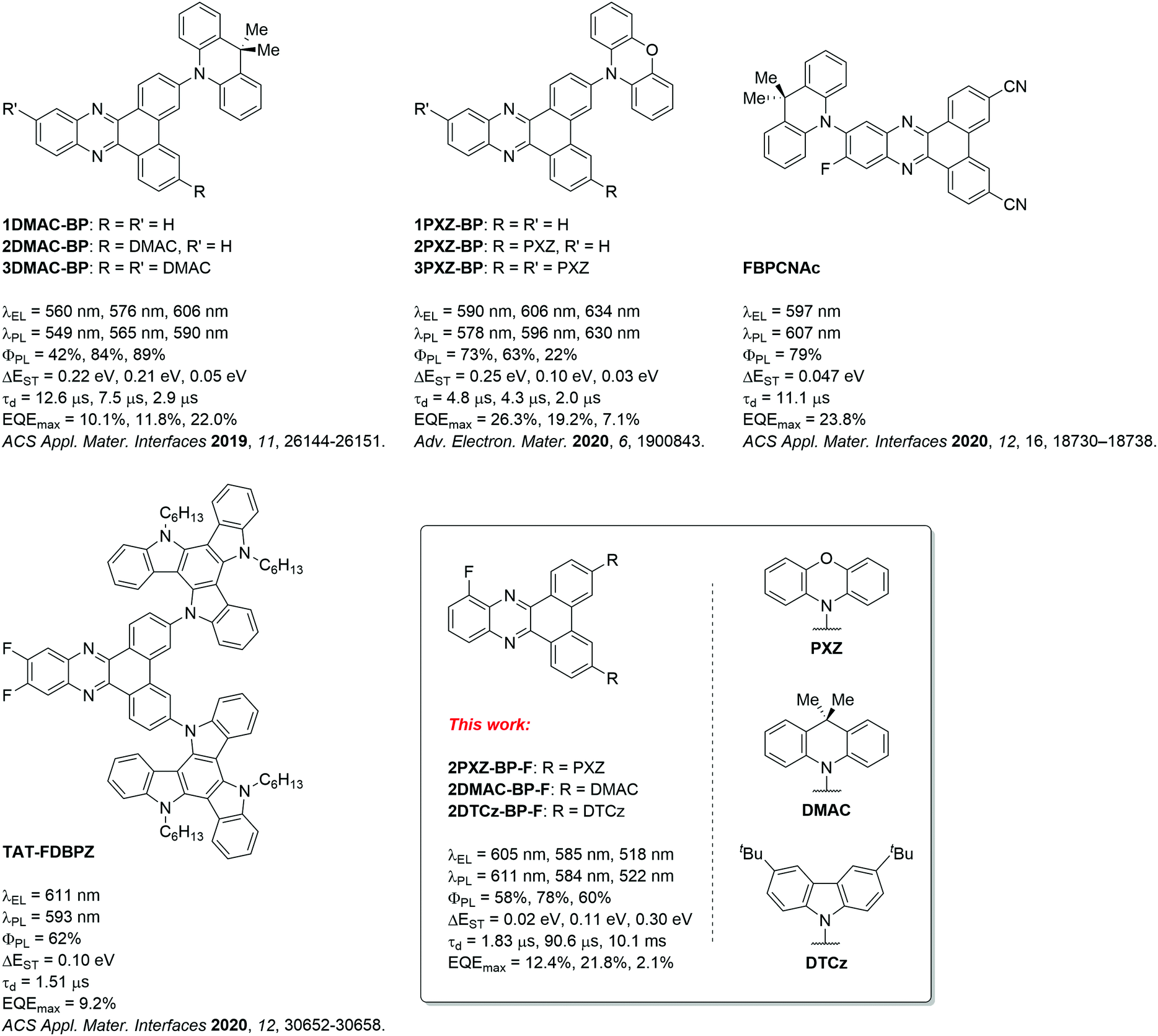 | ||
| Fig. 1 BP-based TADF emitters; DMAC: 9,9-dimethyl-9,10-dihydroacridine, PXZ: 10H-phenoxazine, DTCz: 3,6-di-tert-butylcarbazole. | ||
Building on these findings, we aimed to reduce the molecular weight of the emitter in the context of vacuum-deposited device fabrication. We investigated a compromise of the poly(donor)–acceptor strategy by installing two donor units and an electron-withdrawing fluorine substituent to strengthen the dibenzo[a,c]phenazine acceptor. We designed three new TADF emitters, shown in Fig. 1, based on 10-fluorodibenzo[a,c]phenazine (BP-F), each incorporating two donor moieties, namely 3,6-bis(3,6-di-tert-butyl-9H-carbazol-9-yl)-10-fluorodibenzo[a,c]phenazine (2DTCz-BP-F), 3,6-bis(9,9-dimethylacridin-10(9H)-yl)-10-fluorodibenzo[a,c]phenazine (2DMAC-BP-F) and 10,10′-(10-fluorodibenzo[a,c]phenazine-3,6-diyl)bis(10H-phenoxazine) (2PXZ-BP-F). We successfully applied a modular synthesis strategy that allowed for the facile synthesis of these TADF molecules. The compounds show color tuning based on the choice of donor, emitting from green to deep-red for 2DTCz-BP-F, 2DMAC-BP-F, and 2PXZ-BP-F at peak wavelengths, λPL, of 505 nm, 589 nm, and 674 nm in toluene solution, respectively. 2DMAC-BP-F and 2PXZ-BP-F show small ΔEST of 0.11 eV and 0.02 eV while using the weakest DTCz donor resulted in a compound 2DTCz-BP-F showing the largest ΔEST of 0.30 eV in doped mCBP film (5 wt% 2DTCz-BP-F, 10 wt% 2DMAC-BP-F, and 1.5 wt% 2PXZ-BP-F). The corresponding delayed lifetimes follow the trend in ΔEST at 90.6 μs, 1.83 μs and 10.152 ms, respectively, for 2DMAC-BP-F, 2PXZ-BP-F and 2DTCz-BP-F. The OLEDs fabricated with 2DMAC-BP-F, 2PXZ-BP-F and 2DTCz-BP-F exhibited EQEmax of 21.8%, 12.4% and 2.1% at λEL of 585 nm, 605 nm and 518 nm, respectively.
Results and discussion
Molecular design and synthesis
The synthesis of the 2D-BP-F (D = PXZ, DMAC, DTCz) family of emitters is outlined in Scheme 1. Firstly, 3,6-dibromo-10-fluorodibenzo[a,c]phenazine 3 was synthesized through a condensation reaction of 3-fluorobenzene-1,2-diamine 1 and 3,6-dibromophenantrene-9,10-dione 2 in acetic acid and ethanol at elevated temperatures. Proceeding from intermediate 3, the target compounds 2DTCz-BP-F, 2DMAC-BP-F and 2PXZ-BP-F were obtained through Pd-catalyzed Buchwald–Hartwig cross-coupling reactions in excellent yields. While the catalyst system Pd(OAc)2/P(tBu)3 gave excellent yields for the synthesis of 2DTCz-BP-F and 2DMAC-BP-F, the catalyst system Pd(dba)2/(tBu)3PHBF4 gave higher yields for the synthesis of 2PXZ-BP-F.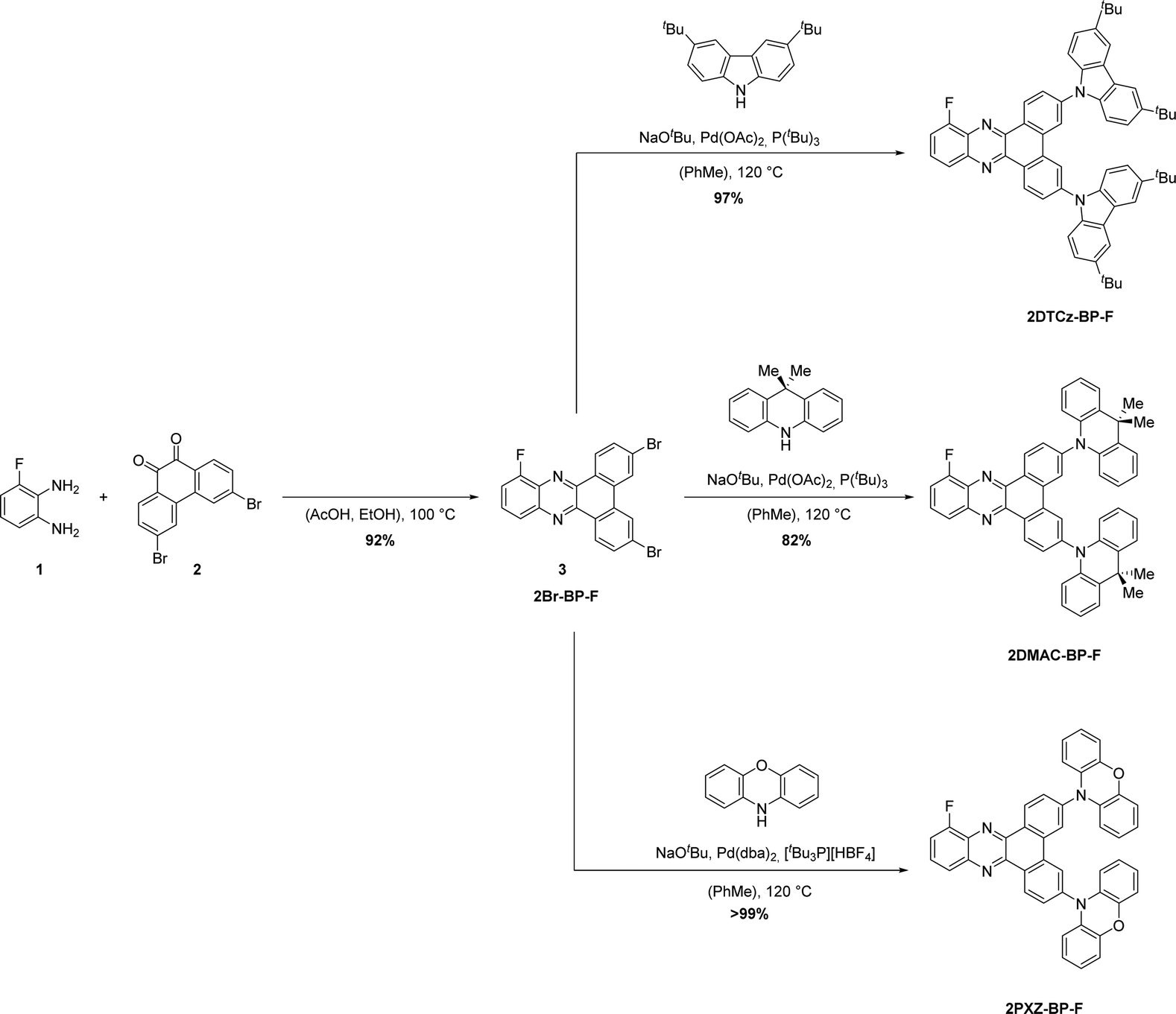 | ||
| Scheme 1 Synthesis of 2DTCz-BP-F, 2DMAC-BP-F, and 2PXZ-BP-F. | ||
The three emitters were purified further by gradient-temperature sublimation. The chemical structure and purity of the three compounds were confirmed using 1H, 13C, and 19F nuclear magnetic resonance (NMR) spectroscopy, high-resolution mass spectrometry (HRMS), infrared spectroscopy, melting point analysis, and elemental analysis (EA). A single crystal suitable for X-ray diffraction analysis was obtained for 2DMAC-BP-F by evaporating a solution in deuterated benzene in an NMR tube at room temperature (Fig. 2a). Analysis of the crystal structure of 2DMAC-BP-F showed that the fluorine atom is disordered about a mirror plane. The DMAC donor units are strongly twisted with a dihedral angle of 65° to the BP acceptor. The DMAC donors display an almost planar conformation with the quaternary carbon being pushed out of the plane by 0.11 Å while the two benzene rings of the DMAC are tilted towards each other by 4°. Crystals of 2DTCz-BP-F were obtained by evaporation of a solution in deuterated chloroform in an NMR tube at room temperature (Fig. 2b). Four crystallographically independent molecules were found with the fluorine atoms disordered about a mirror plane and the donor units strongly twisted with an average dihedral angle of 46.6°. Crystallographic data of both molecules are quoted in the ESI† (Table S1).
 | ||
| Fig. 2 (a) Molecular structure of 2DMAC-BP-F (solvent and one disordered F-position omitted for clarity, displacement parameters are drawn at 30% probability level); (b) the molecular structure of one of the crystallographically independent molecules of 2DTCz-BP-F (solvent and minor disordered F-position omitted for clarity, displacement parameters are drawn at 30% probability level). | ||
Theoretical calculations
The ground-state geometries of 2DTCz-BP-F, 2DMAC-BP-F, and 2PXZ-BP-F were optimized using density functional theory (DFT) at the PBE0/6-31G(d,p) level of theory in the gas phase.17,18 The excited state properties were calculated by time-dependent density functional theory (TD-DFT) within the Tamm–Dancoff approximation (TDA-DFT) based on the optimized ground-state geometries.19 The calculated energy levels of the highest occupied molecular orbits (HOMOs) and lowest unoccupied molecular orbits (LUMOs) are presented in Fig. 3, and the results are summarized in Table S2 (ESI†). The dihedral angles between the donor and acceptor moieties were found to be around 48.6° and 47.6° for 2DTCz-BP-F, 87.9°, and 90.1° for 2DMAC-BP-F and 85.9° and 72.2° for 2PXZ-BP-F, respectively. In comparison with the value obtained from the crystal structure, the dihedral angle between the DMAC and the BP-F groups in 2DMAC-BP-F (65°) was found to be smaller than that theoretically calculated, while the average dihedral angle between the DTCz and the BP-F groups in 2DTCz-BP-F (46.6°) was in good accordance with the calculated value. Due to the almost orthogonal conformations of 2DMAC-BP-F and 2PXZ-BP-F, the HOMO and LUMO distributions are localized on the donor and acceptor moieties, respectively, in both molecules, which results in small ΔEST. The LUMOs of all three compounds are distributed over the BP-F acceptor core, while the HOMOs are generally located on the donor moieties. In the case of 2DTCz-BP-F, the HOMO is mainly localized on both of the 3,6-di-tert-butyl-9H-carbazole (DTCz) units, whereas for 2DMAC-BP-F or 2PXZ-BP-F, the HOMO is mainly found on only one of the donor units while HOMO-1 is localized on the other donor as these two orbitals are pseudo degenerate (Fig. 3). The HOMO–LUMO gap, ΔEHOMO–LUMO, decreases from 3.17 eV for 2DTCz-BP-F to 2.67 eV for 2DMAC-BP-F and 2.39 eV for 2PXZ-BP-F, following a trend of decreasing ΔEHOMO–LUMO with increasing donor strength. The oscillator strength, f, for the transition from S0 to S1 was found to be 0.167, 0, and 0.005 for 2DTCz-BP-Fz, 2DMAC-BP-F, and 2PXZ-BP-F, respectively, which reflects the significantly greater orbital overlap due to the less twisted conformation and weaker nature of the DTCz donor. The S1 energies are 2.73 eV for 2DTCz-BP-F, 2.16 eV for 2DMAC-BP-F, and 1.89 eV for 2PXZ-BP-F, while the T1 energies decrease from 2.37 eV, 2.15 eV, and 1.87 eV, respectively, following a similar trend to that observed for ΔEHOMO–LUMO. The clear spatial separation of the frontier orbitals in 2DMAC-BP-F and 2PXZ-BP-F results in a very small ΔEST of less than 0.02 eV, while the larger overlap between HOMO and LUMO for 2DTCz-BP-F leads to a ΔEST of 0.36 eV.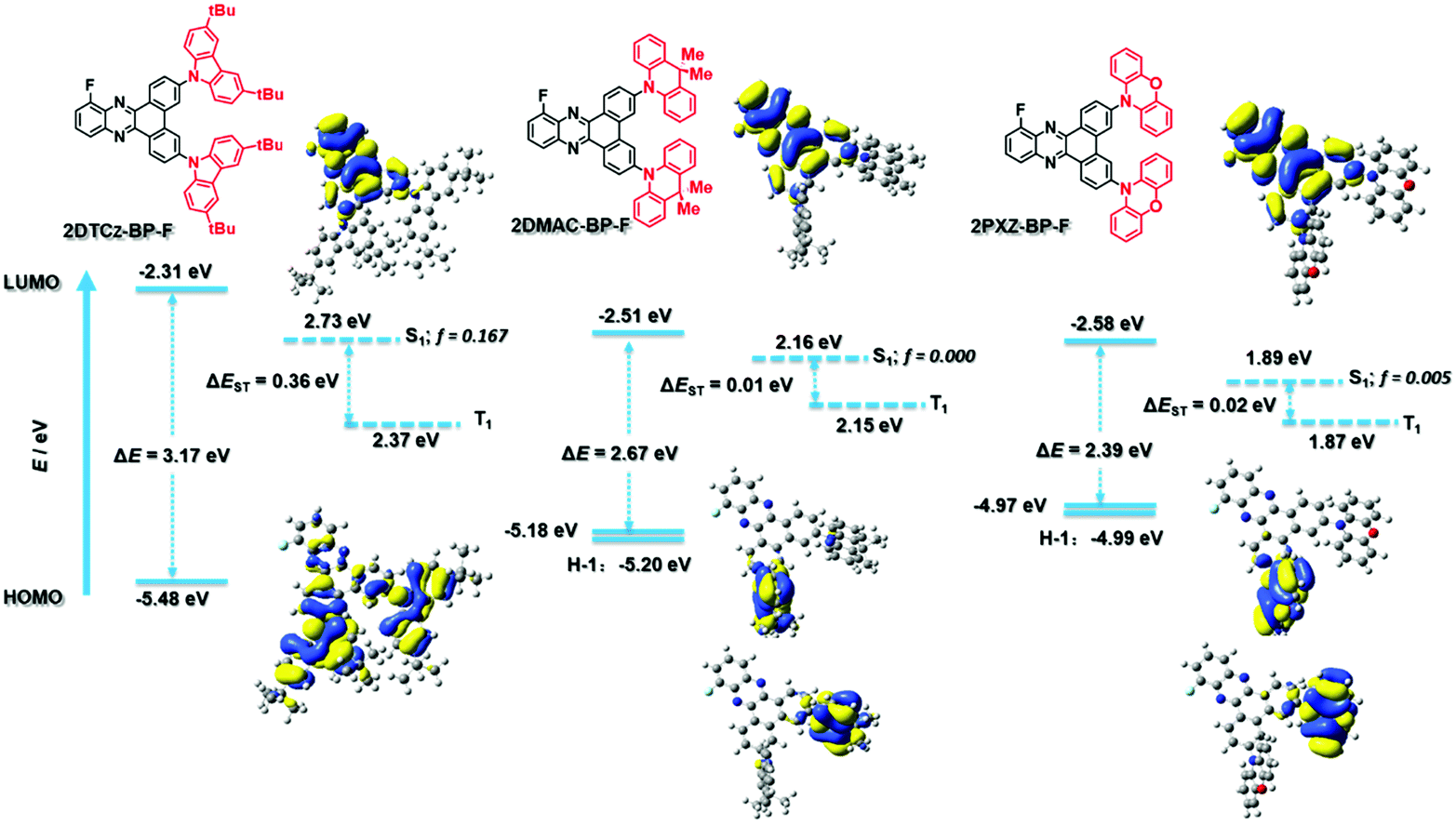 | ||
| Fig. 3 Theoretical modeling of the energies of the HOMO/LUMO orbitals and the S1 and T1 states and oscillator strength of 2DTCz-BP-F, 2DMAC-BP-F, and 2PXZ-BP-F and the electron density distribution (ISO value = 0.02) of the frontier molecular orbitals. | ||
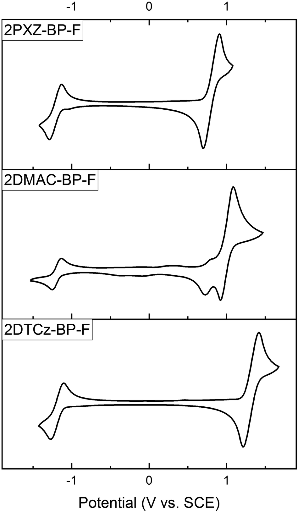
Electrochemistry
Cyclic voltammetry (CV) was performed to determine the HOMO and LUMO levels of the emitters. The oxidation and reduction potentials of the emitters were evaluated in Ar-saturated dichloromethane (DCM) solution with tetrabutylammonium hexafluorophosphate as the supporting electrolyte. The values are reported versus standard calomel electrode (SCE). The results obtained from the CV measurements are summarized in Table 1.| Emitter | E ox [V vs. SCE] | E red [V vs. SCE] | E HOMO [eV] | E LUMO [eV] | ΔEH–Lc [eV] |
|---|---|---|---|---|---|
| a In Ar-saturated DCM (0.1 M [nBu4N]PF6) at a scan rate of 100 mV s−1. Eox/red [V vs. SCE] = Eox/red [V vs. Fc/Fc+] + 0.46.20 b The HOMO and LUMO energies were determined using EHOMO/LUMO = −(Eox/Ered + 4.8) eV where Eox and Ered are anodic and cathodic peak potentials, respectively, versus Fc/Fc+.21–23 c ΔEH–L = |EHOMO − ELUMO|. | |||||
| 2PXZ-BP-F | 0.80 | −1.21 | −5.14 | −3.13 | 2.01 |
| 2DMAC-BP-F | 1.00 | −1.19 | −5.34 | −3.15 | 2.20 |
| 2DTCz-BP-F | 1.32 | −1.18 | −5.66 | −3.16 | 2.50 |
As shown in Fig. 4, all three compounds show reversible oxidation and reduction processes. The main oxidation waves occur at 0.80 V, 1.00 V, and 1.32 V for 2PXZ-BP-F, 2DMAC-BP-F, and 2DTCz-BP-F, respectively. These are each assigned to the oxidation of PXZ, DMAC, and DTCz, and reflect the relative strength of the donors. 2DMAC-BP-F shows an additional minor oxidation wave at 0.77 V, which is characteristic of the redox behavior of DMAC-containing compounds.24 The respective HOMO levels are −5.14 eV, −5.34 eV, and −5.66 eV for 2PXZ-BP-F, 2DMAC-BP-F, and 2DTCz-BP-F. The reduction waves occur at very similar potentials of −1.21 V, −1.19 V, −1.18 V for 2PXZ-BP-F, 2DMAC-BP-F, and 2DTCz-BP-F, respectively, and indicate that the electronic coupling between the donor and acceptor moiety is small.
 | ||
| Fig. 4 Cyclic voltammograms of 2PXZ-BP-F, 2DMAC-BP-F, and 2DTCz-BP-F in Ar-saturated DCM solution (0.1 M [nBu4N][PF6]) at a scan rate of 100 mV s−1. | ||
The corresponding redox gaps, ΔEH–L, decrease from 2.50 V to 2.20 V and 2.01 V for 2DTCz-BP-F, 2DMAC-BP-F, and 2PXZ-BP-F, respectively matches the HOMO–LUMO gap trend predicted by DFT calculations.
Photophysical properties
The UV-vis absorption spectra of the three emitters in dilute toluene are shown in Fig. 5a, and the photophysical properties are summarized in Table 2. All three compounds exhibit strong absorption bands at around 310 nm, which can be attributed to locally excited (LE) π–π* transitions of the donors and BP-F moieties, respectively.24–26 Weaker and broad absorption bands are observed from 410 to 520 nm, which are assigned to ICT transitions from the donor units to the acceptor core.27 This latter band is more intense for 2DTCz-BP-F (λabs = 440 nm, 21 × 103 M−1 cm−1) compared to those of 2DMAC-BP-F (λabs = 415 nm, 3 × 10³ M−1 cm−1) and 2PXZ-BP-F (λabs = 476 nm, 3 × 10³ M−1 cm−1) as the DTCz groups adopt a less twisted conformation, leading to greater conjugation and greater oscillator strength for the ICT transitions in 2DTCz-BP-F, values that are corroborated by the DFT calculations (Fig. S12–S17, ESI†). There is the expected shift to lower energies of the ICT band across the family of compounds that is aligned with increasing donor strength. All compounds exhibit unstructured and broad PL spectra in toluene (Fig. 5a), indicative of an excited state with strong ICT character, with peak maxima, λPL, at 505 nm, 589 nm, and 674 nm for 2DTCz-BP-F, 2DMAC-BP-F, and 2PXZ-BP-F, respectively. Positive solvatochromism is observed for all compounds (Fig. 5a and Table S3, ESI†), which is consistent with the CT nature of the emissive excited state. The optical bandgaps, Eg, calculated from the normalized absorption and emission spectra intersection point, are 2.60 eV, 2.32 eV, and 2.13 eV for 2DTCz-BP-F, 2DMAC-BP-F, and 2PXZ-BP-F, respectively. Except for 2DTCz-BP-F (Eg = 2.60 eV vs. ES1![[thin space (1/6-em)]](https://www.rsc.org/images/entities/char_2009.gif) theory = 2.73 eV), experimental Eg for 2DMAC-BP-F (Eg = 2.32 eV vs. ES1theory = 2.16 eV) and 2PXZ-BP-F (Eg = 2.13 eV vs. ES1theory = 1.89 eV) were found to be larger than those calculated. The photoluminescence quantum yields, ΦPL, in degassed toluene solution of 2DTCz-BP-F, 2DMAC-BP-F, and 2PXZ-BP-F are 51%, 30%, and 8%, respectively. These dropped to 49%, 21%, and 6% upon exposure to oxygen (Table 2). The prompt fluorescence and phosphorescence spectra of all compounds in 2-MeTHF at 77 K were measured to determine the S1 and T1 energies from their respective onsets (Fig. 5b and Fig. S18b, ESI,†Table 2). The S1 energies of 2DTCz-BP-F, 2DMAC-BP-F, and 2PXZ-BP-F are 2.64 eV, 2.47 eV, and 2.23 eV, and the T1 energies are 2.21 eV, 2.27 eV, and 2.28 eV, respectively. The phosphorescence spectra of 2DTCz-BP-F and 2DMAC-BP-F are structured, and each is assigned from TDDFT calculations as a mixed locally excited triplet (3LE) state of the acceptor (BP-F) and charge-transfer (3CT) state (see Fig. S18a and Table S4, ESI†). The phosphorescence spectrum of 2PXZ-BP-F is structureless to a mainly charge-transfer (3CT) state. The ΔEST of 2DTCz-BP-F, 2DMAC-BP-F is 0.43 eV and 0.20 eV, respectively. The phosphorescence spectrum of 2PXZ-BP-F in 2-MeTHF (Fig. 5 and Fig. S18b, ESI†) is slightly blue-shifted compared to the prompt fluorescence, leading to an apparent ΔEST of −0.05 eV, indicating that the emission from these two states results from different conformers. To understand how the solvent polarity affects the energies of S1 and T1 for 2PXZ-BP-F, we measured the prompt fluorescence and phosphorescence spectra in hexane at 77 K, and the ΔEST is 0.05 eV for 2PXZ-BP-F (Fig. 5b bottom). We measured the PL decays of all molecules in toluene under degassed conditions using time-correlated single-photon counting (TCSPC, Fig. S19, ESI†). The ICT band of 2DMAC-BP-F and 2PXZ-BP-F decays with biexponential kinetics with prompt fluorescence lifetimes, τp, of 27.7 ns and 16.9 ns, and delayed fluorescence lifetimes, τd, of 19.0 μs and 0.2 μs, respectively (Fig. S19, ESI† and Table 2). The delayed emission is strongly quenched upon the exposure of oxygen, indicating accessible triplet states. The ICT band of 2DTCz-BP-F decays monoexponentially with τp of 6.6 ns, no delayed emission is observed for this compound.
theory = 2.73 eV), experimental Eg for 2DMAC-BP-F (Eg = 2.32 eV vs. ES1theory = 2.16 eV) and 2PXZ-BP-F (Eg = 2.13 eV vs. ES1theory = 1.89 eV) were found to be larger than those calculated. The photoluminescence quantum yields, ΦPL, in degassed toluene solution of 2DTCz-BP-F, 2DMAC-BP-F, and 2PXZ-BP-F are 51%, 30%, and 8%, respectively. These dropped to 49%, 21%, and 6% upon exposure to oxygen (Table 2). The prompt fluorescence and phosphorescence spectra of all compounds in 2-MeTHF at 77 K were measured to determine the S1 and T1 energies from their respective onsets (Fig. 5b and Fig. S18b, ESI,†Table 2). The S1 energies of 2DTCz-BP-F, 2DMAC-BP-F, and 2PXZ-BP-F are 2.64 eV, 2.47 eV, and 2.23 eV, and the T1 energies are 2.21 eV, 2.27 eV, and 2.28 eV, respectively. The phosphorescence spectra of 2DTCz-BP-F and 2DMAC-BP-F are structured, and each is assigned from TDDFT calculations as a mixed locally excited triplet (3LE) state of the acceptor (BP-F) and charge-transfer (3CT) state (see Fig. S18a and Table S4, ESI†). The phosphorescence spectrum of 2PXZ-BP-F is structureless to a mainly charge-transfer (3CT) state. The ΔEST of 2DTCz-BP-F, 2DMAC-BP-F is 0.43 eV and 0.20 eV, respectively. The phosphorescence spectrum of 2PXZ-BP-F in 2-MeTHF (Fig. 5 and Fig. S18b, ESI†) is slightly blue-shifted compared to the prompt fluorescence, leading to an apparent ΔEST of −0.05 eV, indicating that the emission from these two states results from different conformers. To understand how the solvent polarity affects the energies of S1 and T1 for 2PXZ-BP-F, we measured the prompt fluorescence and phosphorescence spectra in hexane at 77 K, and the ΔEST is 0.05 eV for 2PXZ-BP-F (Fig. 5b bottom). We measured the PL decays of all molecules in toluene under degassed conditions using time-correlated single-photon counting (TCSPC, Fig. S19, ESI†). The ICT band of 2DMAC-BP-F and 2PXZ-BP-F decays with biexponential kinetics with prompt fluorescence lifetimes, τp, of 27.7 ns and 16.9 ns, and delayed fluorescence lifetimes, τd, of 19.0 μs and 0.2 μs, respectively (Fig. S19, ESI† and Table 2). The delayed emission is strongly quenched upon the exposure of oxygen, indicating accessible triplet states. The ICT band of 2DTCz-BP-F decays monoexponentially with τp of 6.6 ns, no delayed emission is observed for this compound.
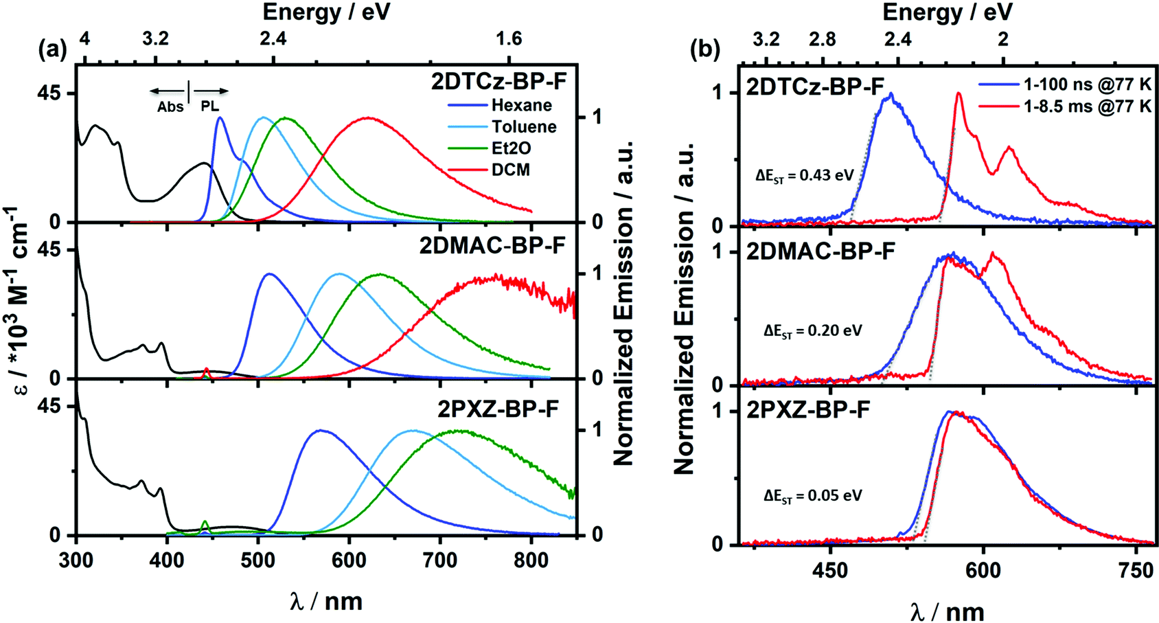 | ||
| Fig. 5 (a) UV-vis absorption and PL solvatochromism study (λexc = 343 nm); (b) prompt fluorescence (blue line) and phosphorescence (red line) spectra of 2DTCz-BP-F and 2DMAC-BP-F in 2-MeTHF, 2PXZ-BP-F in hexane at 77 K (λexc = 343 nm, prompt and delayed fluorescence spectra were obtained in the 1–100 ns and 1–8.5 ms time range, respectively). Et2O = diethyl ether; DCM = dichloromethane. | ||
| Emitter | λ PL [nm] | τ p [ns] | τ d [μs] | S1/T1 [eV] | ΔEST [eV] | Φ PL [%] |
|---|---|---|---|---|---|---|
| a At 298 K, values quoted are in degassed toluene solutions prepared by three freeze–pump–thaw cycles: for λPL the λexc = 343 nm for 2DTCz-BP-F, λexc = 391 nm for 2DMAC-BP-F and 2PXZ-BP-F. For lifetime λexc = 379 nm. ΦPL values inside parenthesis quoted after aeration of a toluene solution. b Obtained from the onset of the prompt fluorescence (time window: 1–100 ns) and phosphorescence spectra (time window: 1–8.5 ms) measured in 2-MeTHF glass at 77 K, λexc = 343 nm. c Thin films of PMMA and mCBP were prepared by spin-coating. Steady-state and time-resolved emission spectra were recorded at 298 K under an O2-free atmosphere (λexc = 343 nm for steady-state and λexc = 379 nm for time-resolved emission). d Average lifetime (τavg = ∑Aiτi2/∑Aiτi, where Ai is the pre-exponential for lifetime τi). Prompt and delayed emissions were measured by TCSPC and MCS, respectively (λexc = 343 nm). e Photoluminescence quantum yields of thin films were determined using an integrating sphere (λexc = 305 nm or 340 nm) under N2 atmosphere at 298 K. Values quoted inside the parentheses are in the presence of O2. | ||||||
| In solution | ||||||
| 2DTCz-BP-F | 505a | 6.6a | — | 2.64/2.21b | 0.43b | 51 (49)a |
| 2DMAC-BP-F | 589a | 27.7a | 19.0a | 2.47/2.27b | 0.20b | 30 (21)a |
| 2PXZ-BP-F | 674a | 16.9a | 0.2a | 2.23/2.28b | −0.05b | 8 (6)a |
| In PMMAc | ||||||
| 2DTCz-BP-F (5 wt%) | 524 | — | 10105d | 2.56/2.22 | 0.34 | 29 (27)e |
| 2DMAC-BP-F (10 wt%) | 588 | — | 5033d | 2.56/2.28 | 0.28 | 48 (34)e |
| 2PXZ-BP-F (1.5 wt%) | 615 | — | 2.99d | 2.34/2.28 | 0.06 | 28 (17)e |
| In mCBPc | ||||||
| 2DTCz-BP-F (5 wt%) | 522 | 4.3d | 10152d | 2.54/2.24 | 0.30 | 60 (47)e |
| 2DMAC-BP-F (10 wt%) | 584 | 19.6d | 90.6d | 2.40/2.29 | 0.11 | 78 (48)e |
| 2PXZ-BP-F (1.5 wt%) | 611 | 31.0d | 1.83d | 2.22/2.20 | 0.02 | 58 (47)e |
To assess the emission properties of these emitters in the solid-state, their photophysical properties were first investigated in PMMA. The PL spectra are unstructured with λPL at 524, 588, and 615 nm for 2DTCz-BP-F, 2DMAC-BP-F, and 2PXZ-BP-F, respectively (Fig. S20, ESI† and Table 2). The optimized ΦPL in doped PMMA films under an N2 atmosphere are 29%, 48%, and 28%, respectively, for 2DTCz-BP-F (5% in PMMA), 2DMAC-BP-F (10% in PMMA), and 2PXZ-BP-F (1.5% in PMMA). The ΦPL values were reduced to 27%, 34%, and 17%, respectively, under air. Multiexponential decay kinetics were observed in the time-resolved decays with average τd values of 10.1 ms, 5.0 ms, and 2.99 μs for 2DTCz-BP-F, 2DMAC-BP-F, and 2PXZ-BP-F, respectively (Fig. S21, ESI† and Table 2). These data are consistent with TADF being operative for the emitters in PMMA films. The S1/T1 energy levels of 2DTCz-BP-F (2.56/2.22 eV), 2DMAC-BP-F (2.56/2.28 eV), and 2PXZ-BP-F (2.34/2.28 eV) in PMMA films are estimated from the onsets of the fluorescence and phosphorescence spectra at 77 K (Fig. S22d–f, ESI†). As a result, 2PXZ-BP-F (0.06 eV) has the smallest ΔEST while 2DMAC-BP-F (0.28 eV) and 2DTCz-BP-F (0.34 eV) show significantly larger singlet–triplet gaps.
We next measured the photophysical properties of all three compounds in an OLED-relevant host 3,3′-di(9H-carbazol-9-yl)-1,1′-biphenyl (mCBP) as this host matrix has sufficiently high triplet energy (T1 = 2.84 eV) to confine the excitons onto the emitter.28 The dopant concentration was varied from 1–10 wt% in doped film to optimize the ΦPL (Table S5, ESI†). The ΦPL of the 5 wt% 2DTCz-BP-F in mCBP doped film is 59.7% at λPL of 522 nm; 10 wt% 2DMAC-BP-F in mCBP doped film is 78.0% at λPL of 584 nm, and 1.5 wt% 2PXZ-BP-F in mCBP doped film is 58.0% at λPL of 611 nm under an N2 atmosphere (Table 2). These ΦPL values decreased in air to 46.8% for 2DTCz-BP-F, 48.3% for 2DMAC-BP-F, and 47.3% for 2PXZ-BP-F. All three compounds show unstructured CT-based emission in mCBP doped film at room temperature, shown in Fig. S22a–c (ESI†). As shown in Fig. 6, all three compounds showed multiexponential decay kinetics with average prompt fluorescence lifetimes, average τp, of 4.3 ns, 19.6 ns, and 31.0 ns and average delayed emission lifetimes, average τd, of 10.15 ms, 90.6 μs and 1.83 μs at room temperature for 2DTCz-BP-F, 2DMAC-BP-F, and 2PXZ-BP-F, respectively. The corresponding rate constants of intersystem crossing (kISC) for the three compounds in mCBP films are 1.09 × 10⁸ s−1, 2.45 × 10⁷ s−1, 1.52 × 10⁷ s−1 for 2DTCz-BP-F, 2DMAC-BP-F, and 2PXZ-BP-F, respectively. The rate constants of reverse intersystem crossing (kRISC) in mCBP films for 2PXZ-BP-F reached 2.41 × 10⁵ s−1, a value much faster than 2DTCz-BP-F of 5.14 × 101 s−1, and 2DMAC-BP-F of 1.33 × 10⁴ s−1, respectively. The relative intensities of the delayed PL increased with increasing temperature from 100 K to 300 K, thereby corroborating the TADF nature of the emission of these three compounds in the mCBP films. The extremely long lifetime and sharp decrease of the emission intensity at low temperature for the 2DTCz-BP-F doped mCBP film can be explained by the large ΔEST (vide infra) and inefficient TADF.
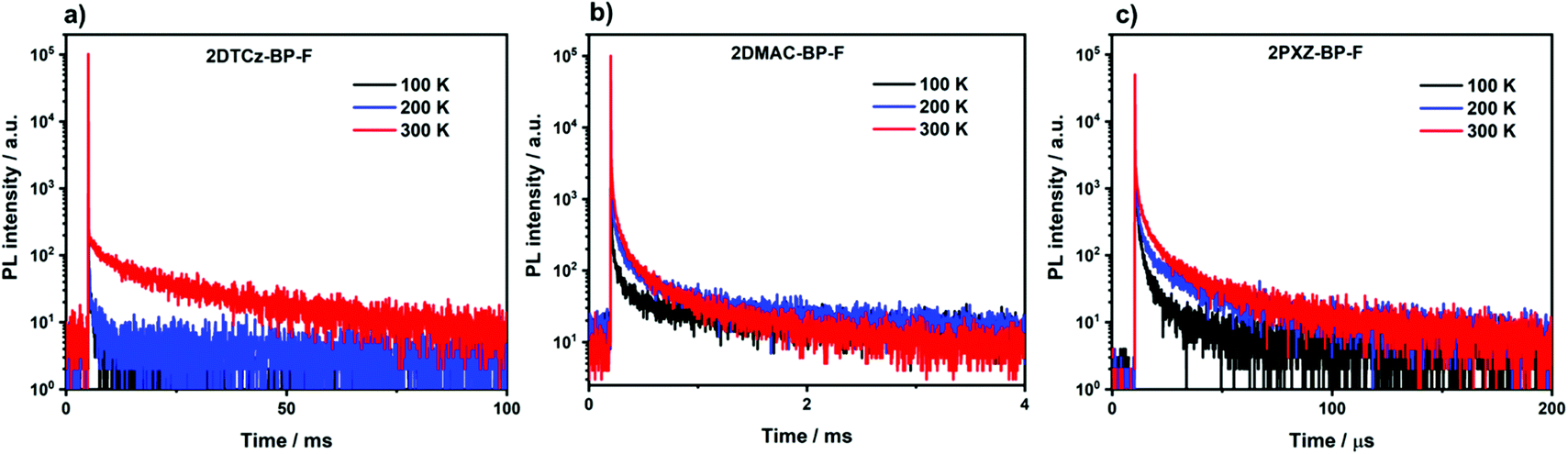 | ||
| Fig. 6 Temperature-dependent time-resolved PL decay of (a) 5 wt% 2DTCz-BP-F doped mCBP film; (b) 10 wt% 2DMAC-BP-F doped mCBP film; (c) 1.5 wt% 2PXZ-BP-F doped mCBP film (λexc = 379 nm). | ||
There is an expectedly large ΔEST of 0.30 eV for 2DTCz-BP-F, while the ΔEST for 2DMAC-BP-F and 2PXZ-BP-F is much smaller at 0.11 eV, and 0.02 eV, respectively. The S1 level of 2DTCz-BP-F in mCBP doped film (S1 = 2.54 eV) is similar to the S1 level of 2DTCz-BP-F in PMMA doped film (S1 = 2.56 eV) and very close to the energy level of 2DTCz-BP-F in 2-MeTHF glass (S1 = 2.64 eV), all of which indicates that the S1 state in 2DTCz-BP-F is of mixed 1LE and 1CT character. The structured phosphorescence and triplet energy level of 2DTCz-BP-F does not change in different media such as PMMA (T1 = 2.22 eV, Fig. S22d, ESI†), mCBP (T1 = 2.24 eV, Fig. S22a, ESI†), and in 2-MeTHF glass (T1 = 2.21 eV, Fig. 5b). Furthermore, these values match with the phosphorescence of the F-BP acceptor (2.26 eV) in 2-MeTHF glass (Fig. S18a, ESI†) and imply that the T1 level of 2DTCz-BP-F has 3LE character. The calculated ΔEST value of 2DTCz-BP-F in PMMA is 0.34 eV and 0.30 eV in mCBP, values that render TADF inefficient. The weak emission band at 522 nm in the millisecond timescale spectra of 2DTCz-BP-F in mCBP and PMMA may be due to residual delayed fluorescence.
The S1 levels of the other two emitters 2DMAC-BP-F and 2PXZ-BP-F in PMMA are 2.56 eV and 2.34 eV, which are significantly blue-shifted in comparison to those in mCBP doped films, for which the S1 level for 2DMAC-BP-F is 2.40 eV, and for 2PXZ-BP-F is 2.22 eV. The T1 level of 2DMAC-BP-F is 2.29 eV, very similar to that in PMMA (2.28 eV for 2DMAC-BP-F) and a value that aligns with the T1 level of the BP-F acceptor in 2-MeTHF (2.26 eV, Fig. S18a, ESI†). However, the T1 level of 2PXZ-BP-F in mCBP is 2.20 eV, which is stabilized from the value measured in PMMA at 2.28 eV (Fig. S22f, ESI† and Table 2). These results reveal that the T1 state in 2DMAC-BP-F possesses dominant 3LE character, while 2PXZ-BP-F shows mainly 3CT character. The estimated ΔEST of 2DMAC-BP-F is 0.11 eV, and of 2PXZ-BP-F is 0.02 eV in mCBP, while the ΔEST in PMMA of 2DMAC-BP-F is 0.28 eV, and of 2PXZ-BP-F is 0.06 eV, which is suitably small for harvesting triplet excitons. Indeed, the small ΔEST of 2DMAC-BP-F and 2PXZ-BP-F is a sign of an efficient TADF emitter for OLEDs.
Device characterization
OLED devices based on 2PXZ-BP-F, 2DMAC-BP-F and 2DTCz-BP-F were fabricated by vacuum deposition following a typical bottom-emitting OLED device architecture (Fig. 7a) that consists of indium tin oxide (ITO)/1,4,5,8,9,11-hexaazatriphenylenehexacarbonitrile (HATCN) (5 nm)/N,N′-di(1-naphthyl)-N,N′-diphenyl-(1,1′-biphenyl)-4,4′-diamine (NPB) (40 nm)/tris(4-carbazoyl-9-ylphenyl)amine (TCTA) (10 nm)/emissive layer (20 nm)/1,3,5-tri[(3-pyridyl)-phen-3-yl]benzene (TmPyPB) (40 nm)/LiF (0.6 nm)/Al (100 nm), where HATCN, NPB and TCTA play the role of hole injection layer (HIL), hole transportation layer (HTL) and electron blocker layer (EBL), respectively. TmPyPB acts both as electron transport layer (ETL) and hole blocking layer due to its deep HOMO (−6.7 eV),29 and LiF acts as an electron injection layer (EIL). The molecular structures of the materials used in these OLEDs are shown in Fig. 7b. The emission layer (EML) comprises 1.5 wt% of 2PXZ-BP-F, 10 wt% 2DMAC-BP-F, or 5 wt% of 2DTCz-BP-F doped into mCBP, based on the doping study discussed above (Table S5, ESI†). The performance of the OLEDs is summarized in Table 3. Current density–voltage–brightness (J–V–L) curves, EQE–luminance curves, and electroluminescence spectra (EL) are given in Fig. 7c. As shown in Fig. 7e, each EL spectrum is similar to that of the corresponding PL spectrum in the thin film with EL maxima, λEL, at 605 nm for 2PXZ-BP-F, 585 nm for 2DMAC-BP-F, and 518 nm for 2DTCz-BP-F. Similar to that observed by PL, the trend in emission energy follows that of increasing donor strength. The corresponding CIE coordinates are (0.55, 0.44), (0.51, 0.48) and (0.29, 0.58) for the devices with 2PXZ-BP-F, 2DMAC-BP-F and 2DTCz-BP-F, respectively. The turn-on voltage of the devices lies between 3.3 V to 3.7 V and is dependent on the energy gap between the HOMO of materials used in HTL and EML layers. The 2DMAC-BP-F based device showed the best overall performance with the highest maximum external quantum efficiency (EQEmax) of 21.8%, a maximum current efficiency (CEmax) of 59.7 cd A−1, and maximum power efficiency (PEmax) of 55.4 lm W−1 (Table 3, Fig. 7d and Fig. S23 and S24, ESI†). The EQEmax of the 2PXZ-BP-F-based device is 12.4% with CEmax = 26.3 cd A−1 and PEmax = 23.0 lm W−1. The 2PXZ-BP-F-based device showed moderate roll-off efficiency, with the EQE at 100 cd m−2 at 9.3% and the EQE at 1000 cd m−2 at 6.3%. The 2DMAC-BP-F-based device, however, showed higher efficiency roll-off, with an EQE at 100 cd m−2 of 8.7% and an EQE of 1000 cd m−2 at 3.3%. The maximum brightness of the 2PXZ-BP-F-based device reached 12350 cd m−2 at an EQE of 2.3%. The relatively low efficiency roll-off in 2PXZ-BP-F originates in part from the low triplet exciton concentration due to the relatively short delayed lifetime (τd = 1.83 μs).30,31 Notably, the 2PXZ-BP-F-based device reached an EQE of 2.5% at 10000 cd m−2 with an emission wavelength beyond 600 nm. Although 2DTCz-BP-F shows a high ΦPL of ca. 60% in the 5 wt% doped in mCBP, the device exhibits a low EQEmax of 2.1%. As a result of the too high ΔEST, the harvesting of triplet excitons in the 2DTCz-BP-F-based device is very inefficient as reflected in the very long delayed lifetime, which causes more triplet–triplet annihilation and triplet–polaron annihilation. Devices fabricated using MoO3 as the HIL showed similar performance but reached lower luminance and low current density than the devices using HATCN (Table S6 and Fig. S25, ESI†).
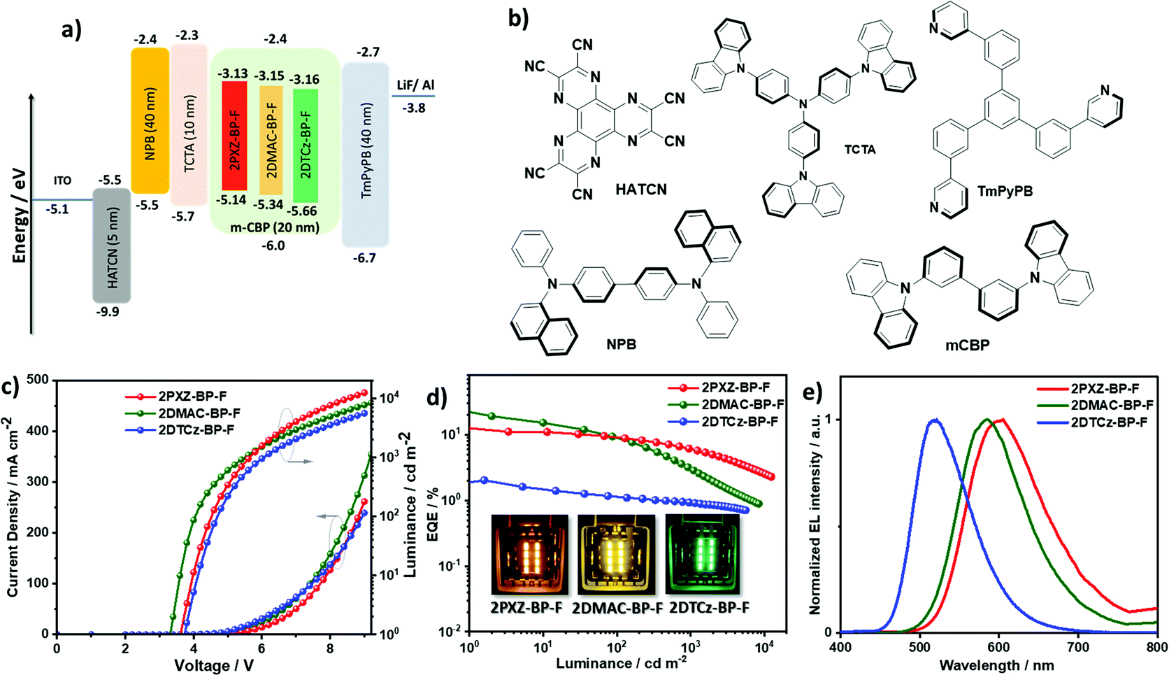 | ||
| Fig. 7 (a) Energy level diagram of materials employed in the devices; (b) molecular structure of materials used in the devices; (c) current density and luminance versus voltage characteristics for the devices; (d) external quantum efficiency versus luminance curves for the devices, the inset is the electroluminescence of 2PXZ-BP-F, 2DMAC-BP-F, and 2DTCz-BP-F; (e) electroluminescence spectra of the device. | ||
| Emitter | Host | V on [V] | λ EL [nm] | CEd [cd A−1] | PEmax [lm W−1] | EQEd [%] | CIEc [x,y] |
|---|---|---|---|---|---|---|---|
| a Device stacks; ITO/HATCN (5 nm)/NPB (40 nm)/TCTA (10 nm)/emissive layer (20 nm)/TmPyPB (40 nm)/LiF (0.6 nm)/Al (100 nm). b The turn-on voltage at a brightness 1 cd m−2. c The electroluminescence maximum and CIE coordinates recorded at 5 V. d The order of measured values: the maximum EQE/EQE at 100 cd m−2/EQE at 1000 cd m−2. | |||||||
| 2PXZ-BP-F | mCBP (1.5%) | 3.3 | 605 | 26.3/19.1/12.7 | 23.0 | 12.4/9.3/6.3 | 0.549, 0.444 |
| 2DMAC-BP-F | mCBP (10%) | 3.6 | 585 | 59.7/23.5/8.1 | 55.4 | 21.8/8.7/3.3 | 0.513, 0.479 |
| 2DTCz-BP-F | mCBP (5%) | 3.7 | 518 | 6.7/3.7/3.0 | 5.6 | 2.1/1.2/1.0 | 0.290, 0.580 |
Conclusions
This study reported a series of green-to-red-emitting fluorine-substituted dibenzo[a,c]phenazine-based (BP-F) TADF emitters. 2DTCz-BP-F, 2DMAC-BP-F, and 2PXZ-BP-F, which showed color tuning based on the choice of donor, emitting from green to deep-red. The rigid and planar constituent groups with large steric hindrance between donor and acceptor units endow these emitters with high ΦPL vlues and suitably small ΔEST. Among them, 2DMAC-BP-F exhibits the highest ΦPL, at 78%, a relatively small ΔEST of 0.11 eV at 584 nm in 10 wt% doped mCBP, whereas 2PXZ-BP-F shows the smallest ΔEST of 0.02 eV with shortest delay lifetime of 1.83 μs at 611 nm in 1.5 wt% doped mCBP. OLED devices using these TADF materials showed excellent performance with an EQEmax of 21.8% in the case of 2DMAC-BP-F with λEL of 585 nm and 12.4% for 2PXZ-BP-F with λEL of 605 nm. The relatively low efficiency roll-off in 2PXZ-BP-F is due to the short delayed lifetime, making this material a very good TADF emitter for OLEDs in the family of devices that can reach brightness above 10000 cd m−2 with an emission wavelength beyond 600 nm. These results demonstrate that simple modification of the BP acceptor with a fluorine substituent is an effective approach to design orange-red/red TADF emitters with devices that show high EQE and low-efficiency roll-off.
Data availability
The research data supporting this publication can be accessed at https://doi.org/10.17630/2553f890-29d1-4fb8-a49c-0cf06404d856.Conflicts of interest
The authors declare no conflict of interest.Acknowledgements
The authors would like to thank the RTG 2039 “Molecular Architectures for Fluorescent Cell Imaging” by the Deutsche Forschungsgemeinschaft (DFG) for financial support. C. S. thanks the China Scholarship Council (201806890001). We thank Dr Tomas Matulaitis for help with ΔEST measurements. A. K. G. is grateful to the Royal Society for Newton International Fellowship NF171163. We acknowledge support from the UK's Engineering and Physical Sciences Research Council (grants EP/P010482/1 and EP/L017008/1). E. Z.-C. is a Royal Society Leverhulme Trust Senior Research fellow (SRF/R1/201089).References
- M. Y. Wong and E. Zysman-Colman, Adv. Mater., 2017, 29, 1605444 CrossRef PubMed.
- G. Hong, X. Gan, C. Leonhardt, Z. Zhang, J. Seibert, J. M. Busch and S. Brase, Adv. Mater., 2021, 33, e2005630 CrossRef PubMed.
- P. de Silva, C. A. Kim, T. Zhu and T. Van Voorhis, Chem. Mater., 2019, 31, 6995–7006 CrossRef CAS.
- J. X. Chen, W. W. Tao, W. C. Chen, Y. F. Xiao, K. Wang, C. Cao, J. Yu, S. Li, F. X. Geng, C. Adachi, C. S. Lee and X. H. Zhang, Angew. Chem., Int. Ed., 2019, 58, 14660–14665 CrossRef CAS PubMed.
- J. Xue, Q. Liang, R. Wang, J. Hou, W. Li, Q. Peng, Z. Shuai and J. Qiao, Adv. Mater., 2019, 31, e1808242 CrossRef PubMed.
- R. Englman and J. Jortner, Mol. Phys., 1970, 18, 145–164 CrossRef CAS.
- J. V. Caspar, E. M. Kober, B. P. Sullivan and T. J. Meyer, J. Am. Chem. Soc., 2002, 104, 630–632 CrossRef.
- J. Eng and T. J. Penfold, Chem. Rec., 2020, 20, 831–856 CrossRef CAS PubMed.
- J. H. Kim, J. H. Yun and J. Y. Lee, Adv. Opt. Mater., 2018, 6, 1800255 CrossRef.
- Q. Zhang, H. Kuwabara, W. J. Potscavage, Jr., S. Huang, Y. Hatae, T. Shibata and C. Adachi, J. Am. Chem. Soc., 2014, 136, 18070–18081 CrossRef CAS PubMed.
- W. Zeng, H. Y. Lai, W. K. Lee, M. Jiao, Y. J. Shiu, C. Zhong, S. Gong, T. Zhou, G. Xie, M. Sarma, K. T. Wong, C. C. Wu and C. Yang, Adv. Mater., 2018, 30, 1704961 CrossRef PubMed.
- L. Yu, Z. Wu, G. Xie, W. Zeng, D. Ma and C. Yang, Chem. Sci., 2018, 9, 1385–1391 RSC.
- F. M. Xie, P. Wu, S. J. Zou, Y. Q. Li, T. Cheng, M. Xie, J. X. Tang and X. Zhao, Adv. Electron. Mater., 2020, 6, 1900843 CrossRef CAS.
- F. M. Xie, H. Z. Li, G. L. Dai, Y. Q. Li, T. Cheng, M. Xie, J. X. Tang and X. Zhao, ACS Appl. Mater. Interfaces, 2019, 11, 26144–26151 CrossRef CAS PubMed.
- S. Kothavale, W. J. Chung and J. Y. Lee, ACS Appl. Mater. Interfaces, 2020, 12, 18730–18738 CrossRef CAS PubMed.
- Y. Liu, Y. Chen, H. Li, S. Wang, X. Wu, H. Tong and L. Wang, ACS Appl. Mater. Interfaces, 2020, 12, 30652–30658 CrossRef CAS PubMed.
- C. Adamo and V. Barone, J. Chem. Phys., 1999, 110, 6158–6170 CrossRef CAS.
- S. Grimme, Chem. Phys. Lett., 1996, 259, 128–137 CrossRef CAS.
- S. Hirata and M. Head-Gordon, Chem. Phys. Lett., 1999, 314, 291–299 CrossRef CAS.
- N. G. Connelly and W. E. Geiger, Chem. Rev., 1996, 96, 877–910 CrossRef CAS PubMed.
- A. J. Bard and L. R. Faulkner, Electrochemical Methods: Fundamentals and Applications, John Wiley & Sons, 1980 Search PubMed.
- M. Thelakkat and H.-W. Schmidt, Adv. Mater., 1998, 10, 219–223 CrossRef CAS.
- J. L. Brédas, R. Silbey, D. S. Boudreaux and R. R. Chance, J. Am. Chem. Soc., 2002, 105, 6555–6559 CrossRef.
- S. Kothavale, W. J. Chung and J. Y. Lee, J. Mater. Chem. C, 2020, 8, 7059–7066 RSC.
- J. X. Chen, K. Wang, C. J. Zheng, M. Zhang, Y. Z. Shi, S. L. Tao, H. Lin, W. Liu, W. W. Tao, X. M. Ou and X. H. Zhang, Adv. Sci., 2018, 5, 1800436 CrossRef PubMed.
- Y.-Y. Wang, Y.-L. Zhang, K. Tong, L. Ding, J. Fan and L.-S. Liao, J. Mater. Chem. C, 2019, 7, 15301–15307 RSC.
- J. X. Chen, W. W. Tao, Y. F. Xiao, K. Wang, M. Zhang, X. C. Fan, W. C. Chen, J. Yu, S. Li, F. X. Geng, X. H. Zhang and C. S. Lee, ACS Appl. Mater. Interfaces, 2019, 11, 29086–29093 CrossRef CAS PubMed.
- S. Gong, X. He, Y. Chen, Z. Jiang, C. Zhong, D. Ma, J. Qin and C. Yang, J. Mater. Chem., 2012, 22, 2894–2899 RSC.
- S. J. Su, T. Chiba, T. Takeda and J. Kido, Adv. Mater., 2008, 20, 2125 CrossRef CAS.
- A. K. Gupta, W. Li, A. Ruseckas, C. Lian, C. L. Carpenter-Warren, D. B. Cordes, A. M. Z. Slawin, D. Jacquemin, I. D. W. Samuel and E. Zysman-Colman, ACS Appl. Mater. Interfaces, 2021, 13, 15459–15474 CrossRef CAS PubMed.
- N. C. Giebink and S. R. Forrest, Phys. Rev. B: Condens. Matter Mater. Phys., 2008, 77, 235215 CrossRef.
Footnotes |
| † Electronic supplementary information (ESI) available: General information, experimental procedures, compound characterization. CCDC 2086119 (2DMAC-BP-F). For ESI and crystallographic data in CIF or other electronic format see DOI: 10.1039/d1tc04918f |
| ‡ Authors contributed equally to this work. |
| This journal is © The Royal Society of Chemistry 2022 |