
 Open Access Article
 This Open Access Article is licensed under a
 Creative Commons Attribution 3.0 Unported Licence
Rapid predictions of the colour purity of luminescent organic molecules†
Shawana A.
Ahmad
,
Julien
Eng
 and
Thomas J.
Penfold
*
and
Thomas J.
Penfold
*
Chemistry - School of Natural and Environmental Sciences, Newcastle University, Newcastle upon Tyne, NE1 7RU, UK. E-mail: tom.penfold@ncl.ac.uk
First published on 7th January 2022
Abstract
Designing luminescent organic materials exhibiting narrowband emission is crucial for achieving high resolution and energy efficient organic light emitting diodes (OLEDs), but remains a significant challenge. Herein we establish the key factors determining the emission full-width at half-maximum (FWHM) of 27 organic functional molecules exhibiting emitting states of different characteristics, including π–π*, charge transfer and multiple-resonance. We demonstrate that the emission FWHM can be interpreted within the displaced harmonic oscillator model (DHO), meaning that predictions can be made using ground state frequency and excited state gradient calculations only. This eliminates the need for time consuming calculations of excited state geometries and Hessians. While formally only valid within the Condon approximation, the DHO model provides reasonable correlations for spectra exhibiting significant Herzberg–Teller effects and not only makes it possible to predict emission FWHM, but also informs on the normal modes responsible for emission band broadening. In addition, quantum chemistry and rate calculations of three multiple-resonance type thermally activated delayed fluorescence (TADF) emitters demonstrates how the importance of direct intersystem crossing (ISC) can be increased when sulphur is used within the B–N framework. Overall, this work offers new perspectives for incorporating considerations of emission FWHM into rational molecular design and high-throughput screening procedures aiming to develop high efficiency luminescent organic materials.
1 Introduction
Luminescent materials that exhibit narrowband emission represent an important challenge in the development of high resolution and energy efficient displays and are becoming increasingly important with the stringent requirements associated with high definition (HD) and ultra-high definition (UHD) displays. Light-emitting diodes (LEDs) based upon gallium nitride1 or quantum dot LEDs2,3 have achieved emission profiles with full-width at half-maximum (FWHM) of <20 nm, however delivering equally high colour purity in organic light emitting diodes (OLEDs) remains a significant challenge.4This is because high performing phosphorescence5 and thermally activated delayed fluorescence (TADF)6 emitters which can achieve 100% internal quantum efficiency (IQE), predominantly use charge-transfer (CT) excited states which often exhibits an inherently broad emission, with a typical FWHM ∼70–120 nm.7 Consequently, commercial devices tend to use filters or optical microcavities8 to enhance the colour purity of the electroluminescence (EL). However, this filtering significantly reduces the external quantum efficiency (EQE) leading to increased power consumption and shorter operational lifetime because the pixels need to run at higher brightness to compensate for this loss. With the ever increasing commercial requirements for high-resolution OLED displays, new emitters achieving both 100% IQE and narrowband emission, obviating the use of colour filters and their associated energy loss, are urgently required.9
Emission broadening is caused by coupling between the electronic and vibrational degrees of freedom, i.e. vibronic coupling.10 Electronic changes occurring upon excitation drive structural dynamics that modulate the energy gap between the S0 and S1 states, increasing the emission FWHM. A particular challenge is for systems that exhibit excited state electron density changes that are delocalised over multiple atoms and in particular are in the bonding region of the molecule. In such cases, as observed in the π–π* excitations in perylene, even small structural changes can give rise to a broad vibronic structure on top of the emission spectrum.11 To overcome this, Hatakeyama et al.12 developed the multi-resonance (MR) concept, based upon on p- and n-doped polycyclic aromatic hydrocarbons. This exploits spatial symmetry (resonance) to separate the frontier orbitals involved in the low-lying excited states and minimise their bonding/antibonding character. The resulting non-bonding molecular orbitals (MOs) minimise the vibronic coupling, leading to narrow luminescence. The multi-resonance effect also reduces the exchange interaction making these materials suitable for application in thermally activated delayed fluorescence (TADF) and the success of this approach has led to a significant number of experimental11,13–21 and theoretical22–24 investigations into these systems, which have achieved high-performing 3rd-generation11 and Hyper-fluorescence OLEDs.25
Despite the importance of the emission FWHM, there are few computational studies computing and/or predicting the emission FWHM of luminescent organic materials.11,26,27 This is likely, at least in part, associated with the computational expense of calculating emission spectra from first principles which usually requires computation of ground and excited state geometries and Hessians.28–30 Indeed, even with the huge progress in the speed of quantum chemistry methods, it remains a significant challenge to perform such calculations on a large set of molecules as would be required if one were to incorporate the consideration of emission FWHM into high-throughput screening approaches.31,32 Recently, Ansari et al.33 used a combination of experiment and theory to study the origin of the broad emission in TADF emitters. They concluded, based upon careful characterisation of donor–acceptor (D–A) based TADF emitters that the dominant factor was the charge transfer character of the molecule measured by the overlap between the HOMO and LUMO orbitals involved in the lowest excited states.
While, the authors demonstrated a strong correlation for 5 D–A TADF molecules, this approach does not take into account vibronic coupling and is therefore unlikely to be widely applicable beyond D–A type materials. Consequently, in this paper we study 27 organic molecules exhibiting emitting states of different characteristics, including π–π*, CT and MR to establish the key aspects responsible for emission FWHM. We demonstrate that the emission width can be interpreted/predicted using the displaced harmonic oscillator model (DHO). Subsequently, we use quantum chemistry and rate calculations of three of the narrowband MR-type TADF emitters to provide insight into the balance between direct and spin-vibronic34–37 intersystem crossing (ISC) pathways, with the relative contribution of the former increased when sulphur is used within the B–N framework to increase the spin–orbit coupling and reduce the energy gap between the coupled S1 and T1 states. This, along with the DHO model offers new perspectives for improving rational molecular design and/or high-throughput screening procedures for developing high efficiency MR-TADF emitters.
2 Theory and computational details
2.1 Molecular structures
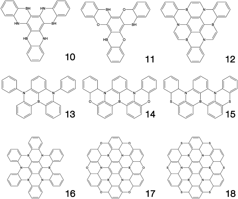
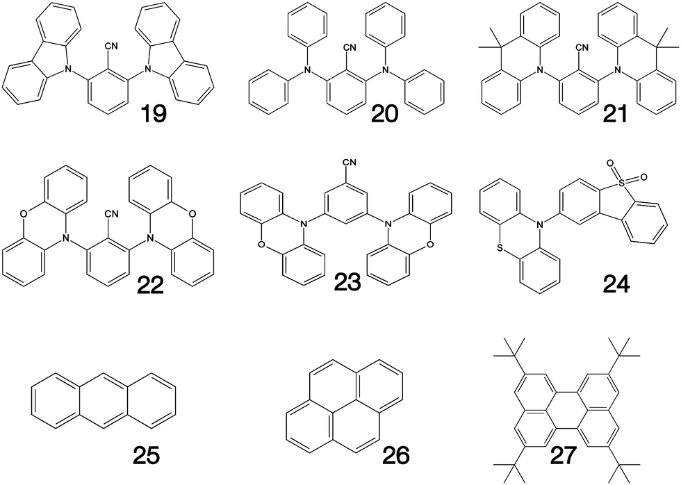
Fig. 1–3 shows the 27 molecules considered in this work. Molecules 1–9 are based upon 10,15-dihydro-5H-diindeno[1,2-a;1,2-c]fluorene, commonly known as truxene.38 This planar heptacyclic polyarene structure, obtained by trimerization of indan-1-one, has recently attracted a lot of attention in organic electronics due to its exceptional solubility, high thermal stability and ease of modification.39–45 Molecules 10–18 are based upon the MR concept, which incorporates nitrogen atoms substituted in the para-position relative to a central boron atom, to exploit the opposite resonance effect of the two atoms to localised the electronic structure onto atomic sites reducing vibronic coupling and minimising the energy gap between singlet and triplet states.11,12 Molecules 19–24 are D–A type materials which exhibit CT type emission33,46 and molecules 25–27 are polycyclic aromatic hydrocarbons exhibiting low-lying π–π* states.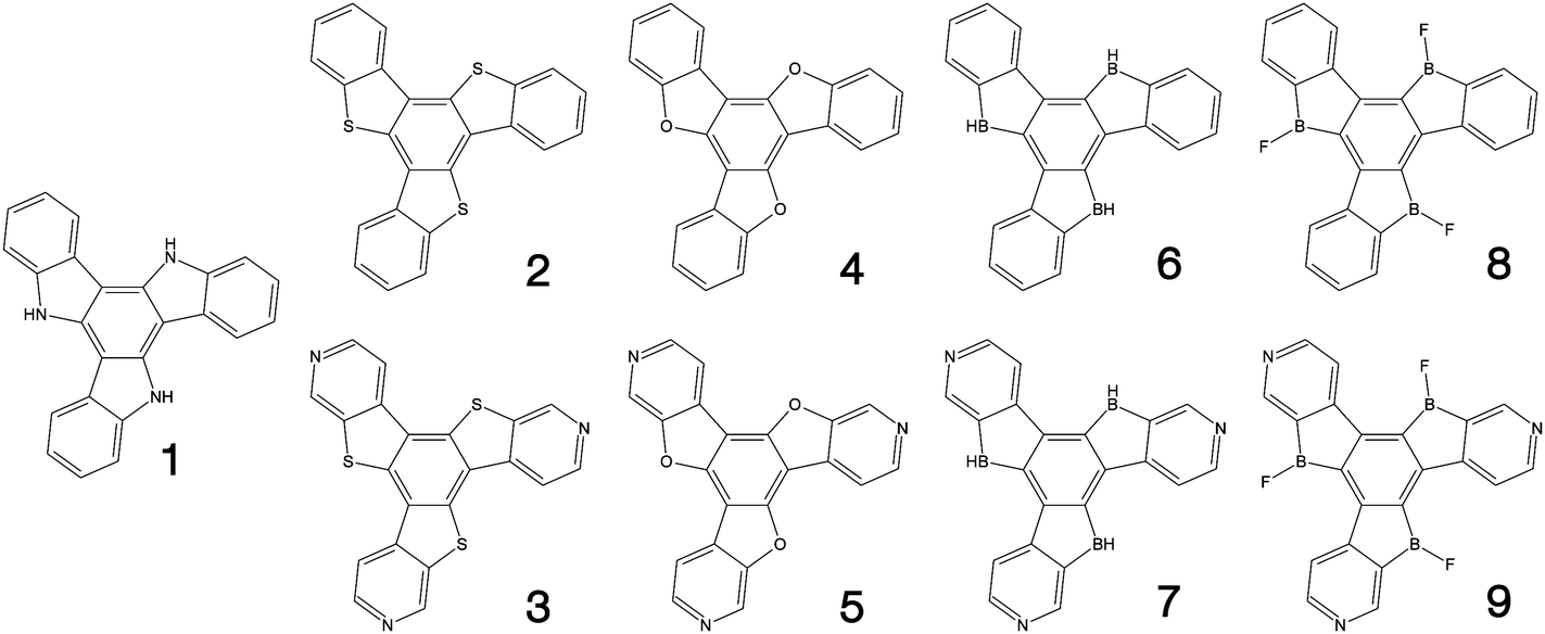 | ||
| Fig. 1 Truxene-type structures considered in this work. | ||
 | ||
| Fig. 2 Multi-resonance type structures considered in this work. | ||
 | ||
| Fig. 3 Charge transfer (19–24) and polycyclic aromatic (25–27) type structures considered in this work. | ||
2.2 Quantum chemistry and fluorescence spectra simulations
Density functional theory (DFT) and linear-response time-dependent density functional theory (LR-TDDFT) simulations were performed within the approximation of the B3LYP exchange and correlation functional47–50 as implemented within the ORCA 4.2.1 quantum chemistry package.51 A def2-SVP basis set was used throughout.52 Frequency calculations were used to verify that optimised geometries were true minima and not saddle points. CC2 simulations were performed using the Turbomole quantum chemistry package53 at the TDDFT optimised S1 geometry using a def2-TZVP basis set.52 The spin–orbit coupling calculations were computed using TDDFT and the SOMF(1X) within the Breit Pauli approximation implemented within the ORCA quantum chemistry package.54 These were calculated at the TDDFT optimised S1 geometry using a def2-TZVP basis set and the ZORA method.The absolute overlap between the HOMO and LUMO orbitals were calculated as:
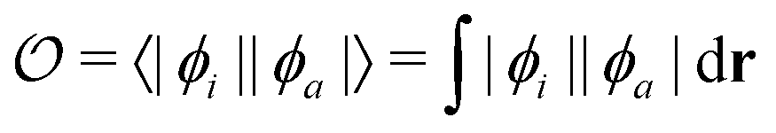 | (1) |
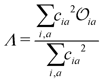 | (2) |
The fluorescence spectra were calculated using the first principles path integral approach30 implemented within the ORCA quantum chemistry package.51 Here, the initial (S1 optimised geometry) and final (ground state optimised geometry) states and their respective Hessian matrices are computed. This is used to compute the Duschinsky rotation matrix and displacement vector. Subsequently, the derivatives for the transition dipoles are computed. The spectrum is calculated as a Discrete Fourier Transform of the transition dipole correlation function, including both the well-known Franck–Condon and so-called Herzberg–Teller (HT) effects.10 Throughout the temperature was set to 300 K and the stick spectrum was broadened using a Voigt function with line widths of 50 cm−1 for the Lorentzian component and 250 cm−1 for the Gaussian component.
2.3 The displaced harmonic oscillator model
The method described in the previous section provides a first principles approach to computing fluorescence spectra, but can be time-consuming for larger molecules. The focus of the present paper is to develop an approach to speed up the prediction of emission bandwidth which will be achieved within the framework of the displaced harmonic oscillator (DHO), shown schematically in Fig. 4.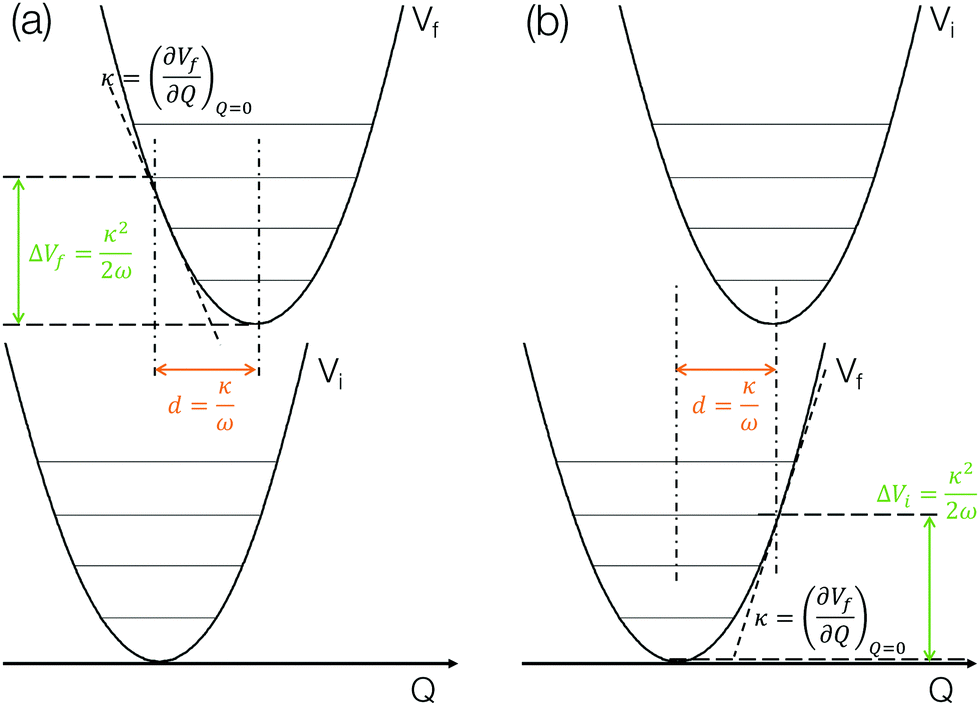 | ||
| Fig. 4 A potential schematic representation of the displaced harmonic oscillator model including the key insights that can be obtained and the components required to estimate the FWHM for the lowest (a) absorption and (b) emission bands. | ||
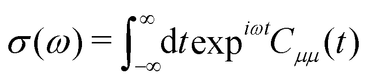
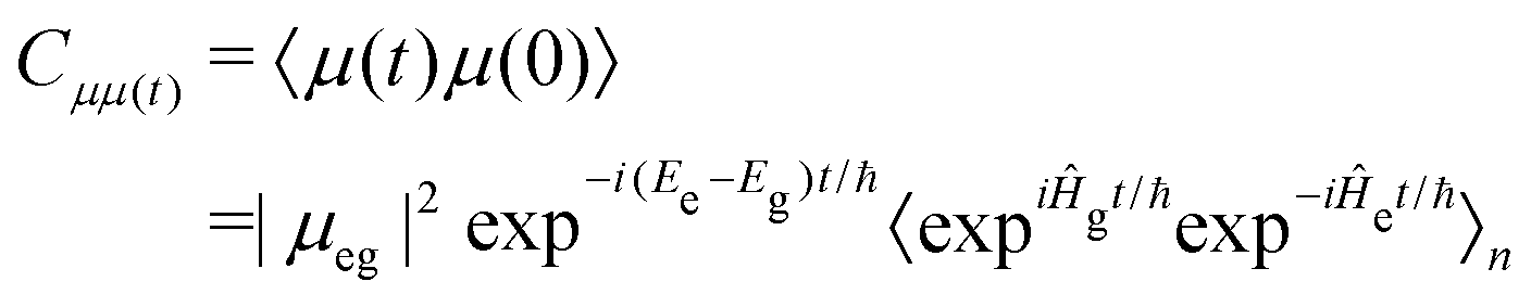
An absorption spectrum can be calculated using the Fourier transform of the dipole correlation function:
 | (3) |
 | (4) |
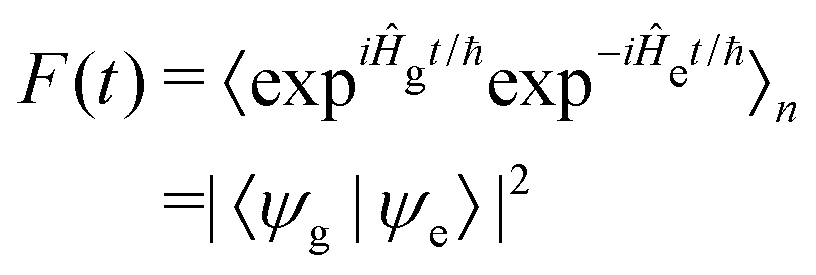 | (5) |
![[p with combining circumflex]](https://www.rsc.org/images/entities/i_char_0070_0302.gif) d/ℏ and allows F(t) to be written as:
d/ℏ and allows F(t) to be written as: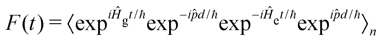 | (6) |
 | (7) |
 | (8) |
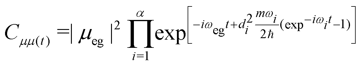 | (9) |
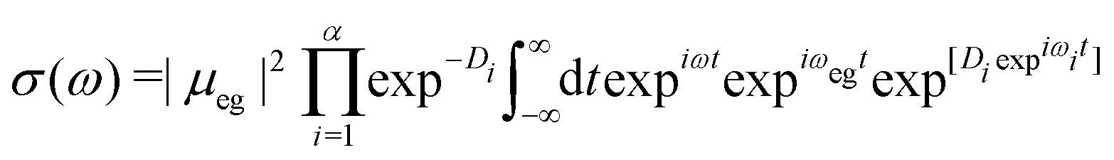 | (10) |
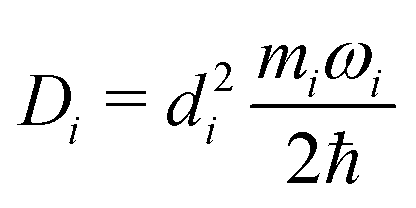 | (11) |
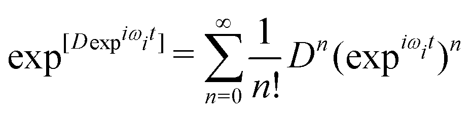 | (12) |
 | (13) |
 | (14) |
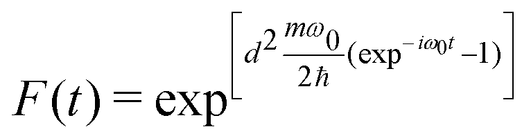
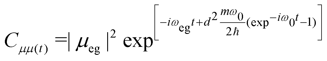
 . While the above is presented in the context of one vibrational mode, the DHO is easily extendable to a set of orthogonal harmonic motions, i.e. molecular normal modes.56
The above discussion illustrates how the DHO model can be used to predict the FWHM of an absorption/emission band and the key aspects are shown in Fig. 4. This is (i) within the limit of the Condon approximation, i.e. the transition dipole moment does not depend on nuclear configuration and (ii) assuming the normal modes of the ground and excited state are the same, i.e. the Duschinsky rotation matrix is an identity matrix. We note that Fig. 4a corresponds to the lowest absorption band, in which the gradient of the S1 state at the ground state optimised geometry in performed. For emission, the gradient of the S0 state at the S1 state optimised geometry needs to be performed, as shown in Fig. 4b. In the present work we perform both and discuss the correlations with the emission FWHM below.
3 Results
3.1 Calculated emission spectra
Fig. 5 shows the calculated emission spectra for 1, 13, 14 and 15 plotted against experimental spectra reproduced from ref. 12, 20 and 42. The remaining computed spectra are all shown in the ESI.† In each case, with the exception of the low energy vibronic structure observed for 15 (Fig. 5d) the calculated spectral shape is in good agreement with their experimental counterpart providing confidence in the theoretical approach used.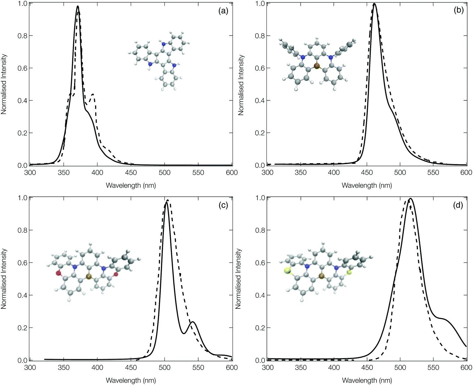 | ||
| Fig. 5 The experimental (dashed) and computed (solid) emission spectra of 1 (a), 13 (b), 14 (c) and 15 (d). In order to facilitate a more direct comparison between experiment and theory, the computed spectra of 1, 13 and 15 have been shifted down by 20, 20 and 50 nm, respectively. The experimental spectra have been reproduced from ref. 12, 20 and 42. | ||
The emission spectrum of 1 has the smallest FWHM, with the side bands forming the vibrational progression separated by ∼0.17 eV. This is driven by the normal mode exhibiting the largest displacement between the ground and excited state (ν81, see Fig. S20, ESI†), which is dominated by a hydrogen wagging and slight breathing motion of the carbon–carbon bonds in the main structure. For 13, commonly known as DABNA-1,12 the vibronic progression has a separation of ∼0.16 eV which arises from 2 dominant normal modes (ν112 and ν123, the former is shown in Fig. S32, ESI†) which corresponds to breathing and stretching motions of the central B,N-core. Molecules 14 and 15 aim at rigidifying the DABNA-1 skeleton by incorporating oxygen or sulphur atoms, respectively. However, both of these molecules exhibit a slightly broader emission spectra which is because, as shown in Fig. S33 and S34 (ESI†), the non-planar structure associated with 14 and 15 means that the density change in the excited state is more delocalised compared to the atom site centred density change of 13. In addition, although the dominant vibrational modes contributing to this emission FWHM remains primarily breathing and stretching of the central B,N-core, the fusing of the oxygen and sulphur atoms into the B–N based framework means these normal modes become delocalised over the whole structure.
3.2 Charge transfer as a metric for emission width
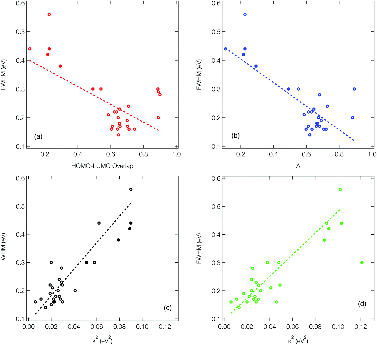
As outlined in the introduction, Ansari et al.33 recently demonstrated for a series of CT emitters correlation between emission FWHM and HOMO–LUMO overlap (![[scr O, script letter O]](https://www.rsc.org/images/entities/char_e52e.gif) , eqn (1)). Fig. 6a shows a plot of FWHM against with the corresponding numerical data available in Table S1 (ESI†) for all 27 molecules. Although a correlation is observed it is not strong, as indicated by the R2 = 0.34 obtained from the line of the best fit (dashed line). While a transition between HOMO and LUMO orbitals is often a good approximation to describe low-lying CT state, not all of the molecules studied herein can be described using a pure HOMO–LUMO basis, which contributes to the low correlation seen in Fig. 6a.
, eqn (1)). Fig. 6a shows a plot of FWHM against with the corresponding numerical data available in Table S1 (ESI†) for all 27 molecules. Although a correlation is observed it is not strong, as indicated by the R2 = 0.34 obtained from the line of the best fit (dashed line). While a transition between HOMO and LUMO orbitals is often a good approximation to describe low-lying CT state, not all of the molecules studied herein can be described using a pure HOMO–LUMO basis, which contributes to the low correlation seen in Fig. 6a.
 | ||
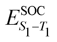
| Fig. 6 The correlation between emission FWHM and (a) HOMO–LUMO overlap, (b) Λ diagnostic, (c) κ2 analysed using the S1 gradient at the ground state geometry and (d) κ2 analysed using the ground state gradient at the S1 geometry. The open circles correspond to molecules where the calculated FWHM has been used. The filled circles correspond to molecules where we were unable to compute the spectra and so the experimental FWHM have been used. The dashed lined shows a linear fit to the data, excluding the data points based upon experimental FWHM. | ||
Consequently, Fig. 6b (corresponding numerical data in Table 1) shows the correlation between emission FWHM and Λ (eqn (2)). This slightly improves the correlation, as shown by the R2 = 0.49. This improvement occurs primarily due to a better description of molecules whose excited states are not well approximated by a HOMO–LUMO transition and therefore poorly described using , for example molecule 26 as shown by the difference between and Λ in Table S1 (ESI†). The excited state energy of CT states exhibit a 1/R dependence, where R is the distance between the donor and acceptor groups. Consequently, small structural changes will be responsible for large energy fluctuations and therefore a broad FWHM. It therefore follows that a significant variation in orbital overlap or CT character of the state will allow a trend with FWHM to be established. However, as can be observed in Fig. 6a and b, for molecules exhibiting similar CT character, a trend between FWHM and either or Λ is far less clear. An alternative approach not explored in the present work is the use of the natural transition orbitals (NTOs). It could be interesting to see how these descriptors computed on the basis of the NTOs correlate with the FWHM, however like while this analysis, like and Λ can be performed very quickly, it provides no insight into the normal modes responsible for the structural changes and broadening of the emission spectrum. Consequently, in the following section we move to the DHO model to establish a clearer trend and understanding.
| Λ | κ GS 2/eV2 | κ S1 2/eV2 | FWHM/eV | ||
|---|---|---|---|---|---|
| Theo. | Expt. | ||||
| 1 | 0.720 | 0.023 | 0.020 | 0.16 | 0.1442 |
| 2 | 0.727 | 0.027 | 0.024 | 0.24 | — |
| 3 | 0.663 | 0.024 | 0.022 | 0.18 | — |
| 4 | 0.706 | 0.030 | 0.028 | 0.16 | — |
| 5 | 0.680 | 0.028 | 0.026 | 0.17 | — |
| 6 | 0.674 | 0.026 | 0.024 | 0.20 | — |
| 7 | 0.667 | 0.027 | 0.027 | 0.18 | — |
| 8 | 0.646 | 0.029 | 0.028 | 0.23 | — |
| 9 | 0.631 | 0.030 | 0.030 | 0.22 | — |
| 10 | 0.690 | 0.019 | 0.017 | 0.19 | — |
| 11 | 0.621 | 0.015 | 0.013 | 0.14 | — |
| 12 | 0.661 | 0.011 | 0.011 | 0.17 | — |
| 13 | 0.598 | 0.022 | 0.046 | 0.16 | 0.1912 |
| 14 | 0.611 | 0.022 | 0.030 | 0.17 | 0.1820 |
| 15 | 0.586 | 0.021 | 0.041 | 0.21 | 0.2020 |
| 16 | 0.634 | 0.006 | 0.006 | 0.16 | — |
| 17 | 0.613 | 0.019 | 0.049 | 0.22 | — |
| 18 | 0.552 | 0.020 | 0.038 | 0.30 | — |
| 19 | 0.293 | 0.079 | 0.088 | — | 0.3833 |
| 20 | 0.492 | 0.051 | 0.121 | — | 0.3033 |
| 21 | 0.217 | 0.089 | 0.092 | — | 0.4233 |
| 22 | 0.219 | 0.089 | 0.103 | — | 0.4433 |
| 23 | 0.226 | 0.090 | 0.102 | 0.56 | 0.4833 |
| 24 | 0.108 | 0.062 | 0.090 | 0.44 | 0.3946 |
| 25 | 0.891 | 0.058 | 0.048 | 0.30 | 0.3557 |
| 26 | 0.680 | 0.029 | 0.025 | 0.28 | 0.2458 |
| 27 | 0.881 | 0.041 | 0.032 | 0.20 | 0.2959 |
3.3 Displaced HO model to estimate emission width
Fig. 6c (corresponding numerical data in Table 1) shows the κGS2 extracted from the DHO model. In this first example the calculations have been performed at the ground state optimised geometry and therefore as illustrated in Fig. 4a, strictly corresponds to the width of the first absorption peak. In the present work we use this as a proxy for the emission FWHM and given the little configurational reorganisation between the ground and excited states for all of these molecules, it is expected to represent a good approximation. Importantly, this shows a significantly stronger correlation than observed using the CT metrics, discussed in the previous section, supported by the R2 = 0.77. Fig. 6d shows the same trend, but in this case the gradient calculation has been performed in the electronic ground state at the S1 optimised geometry as shown schematically in Fig. 4b. While this more rigorously corresponds to the emission FWHM, we observe a slightly weaker correlation with R2 = 0.70. This is associated with the requirement to optimise geometries using TDDFT, which can pose problems for the CT-60,61 and MR-type22 emitters.While Fig. 6c and d show a correlation between κ2 and FWHM, there are clearly a cluster of data points at κ2 < 0.05 eV2 which requires further investigation. Fig. S1 (ESI†) shows the same data presented in Fig. 6c with the MR and truxene type emitters highlighted. In this case, R2 is significantly lower, which is due to the larger effect the Herzberg–Teller component of the spectrum has on the FWHM of these spectra. Indeed, in Fig. S2 (ESI†), the same correlation for spectra calculated within the Condon approximation is shown. In this case although the correlation remains strong, and the slightly weaker correlation for the truxene and MR emitters compared to the overall sample is due to the smaller range of κ values. This highlights a limitation of the DHO, which does not include effects beyond the Condon approximation and therefore could be problematic for systems dominated by the Herzberg–Teller terms. However, many of the spectra presented herein have significant Herzberg–Teller contributions meaning that it remains a useful tool.
The identified correlations illustrate a relatively easy to calculate metric which can be related to the emission FWHM. However, beyond these correlations between FWHM and κ2, the DHO makes it possible to easily identify specific normal modes which contribute most strongly to the FWHM. As outlined in the introduction, this is most prominent for emitting states which exhibit electronic structure changes delocalised over multiple atoms, as vibrational motion will most strongly effect the excited state energy leading to a broader FWHM. This scenario is most clearly observed in the π-conjugated organic fluorophores; 25, 26 and 27. In these cases, as shown in Fig. S44–S46 (ESI†), the density difference between the ground and excited state primarily occurs between the atoms, due to the π–π* excitations. Here the occupation of the anti-bonding orbitals leads to structural changes of the conjugated core, giving rise to a strong vibronic progression on the emission with peaks separated by ∼0.2 eV, i.e. the vibrational frequency of double bonded carbons.
For both the truxene-based molecules (1–9) and multiple-resonance emitters (10–18), the density difference plots shown in Fig. S20–S38 (ESI†) exhibit density differences which are more localised on atomic sites, minimising their bonding/antibonding character and therefore the vibronic coupling in the excited state of the molecules. This is responsible for the narrower FWHM observed. As described above for 1, the FWHM of the truxene-based molecules is largely controlled by hydrogen wagging and slight breathing motion of the carbon–carbon bonds in the main structure. For 2 the contribution of the carbon–carbon breathing mode is enlarged contributing to the larger FWHM. For 6, 8 and 9 an asymmetric stretch of the central 6 membered carbon ring, as shown in Fig. S25, S27 and S28 (ESI†) is responsible for the emission FWHM.
For the MR type emitters (10–18), the FWHM is dominated by breathing and stretching of the central B,N-core. For 17 and 18, the extended π-system combined with the oxygen and sulphur fused into the framework leads to a non-planar structure. As shown in the density difference plots in Fig. S36 and S37 (ESI†) this gives rise to some CT character and delocalisation of the density changes over the bonding regions, consequently a broader emission.
3.4 Excited states properties of 13, 14 and 15
Having established the correlation between emission FWHM and κ2 in the previous section, in this final part we take a deeper look into 13, 14 and 15, known in the literature as DABNA-1,12 2PXZBN and 2PTZBN,20 respectively. As outlined in the introduction, the ISC/rISC mechanism of 13 has been widely studied in the literature22–24 with a general consensus that spin-vibronic coupling is important62–64 due to the weak nature of direct coupling arising from the small spin orbit coupling between the S1 and T1 states. The focus in the present case is the influence of incorporating oxygen and sulphur into the B–N framework to enhance ISC.Table 2 shows the excited state energies computed using TDDFT or CC2 for the lowest singlet and triplet states of each system. All calculations were performed at the S1 optimised geometry, except those also requiring the T1 state, i.e. λ and ΔES1–T1. The TDDFT energetics for the S1 state are in reasonable agreement with the CC2 calculations. However, as previously discussed in ref. 22, the singlet–triplet gap is very different due to the improved treatment of electron correlation in CC2 which is important in the MR-type emitters. Indeed, for all three molecules, the CC2 energies compare well to the fluorescence and phosphorescence spectra reported in ref. 12 and 20. The higher lying triplet states (T2 and T3), which have been invoked in the spin-vibronic mechanism23,24 are also shown and important in the context of this mechanism is that fusing O and S into the B–N framework appears to lower the energy gap between the lowest and higher lying triplets states which would lead to more effective mixing of the states. Finally, Table 2 also shows the spin orbit coupling between the singlet and triplet states. This clearly demonstrates inclusion of the O and S atoms increases SOC, important for ISC.
| Method | E S1 | E T1 | E T2 | E T3 | SS | λ | ΔES1–T1 |
|
|
|
k calcISC | k exptISC | |
|---|---|---|---|---|---|---|---|---|---|---|---|---|---|
| 13 | TDDFT | 2.94 | 2.49 | 3.18 | 3.30 | 0.18 | 0.03 | 0.42 | 0.04 | 0.30 | 0.35 | 9.71 × 10² | 4.5 × 10⁶ |
| LR-CC2 | 2.82 | 2.68 | 3.42 | 3.49 | — | — | 0.14 | — | — | — | |||
| 14 | TDDFT | 2.59 | 2.12 | 2.48 | 2.91 | 0.21 | 0.02 | 0.35 | 0.05 | 0.53 | 0.89 | 4.0 × 10² | 3.27 × 10⁷ |
| LR-CC2 | 2.43 | 2.29 | 2.69 | 3.14 | — | — | 0.13 | — | — | — | |||
| 15 | TDDFT. | 2.46 | 2.07 | 2.47 | 2.94 | 0.24 | 0.03 | 0.37 | 0.24 | 0.65 | 0.74 | 2.21 × 10⁶ | 6.67 × 10⁷ |
| LR-CC2 | 2.37 | 2.26 | 2.71 | 3.16 | — | — | 0.10 | — | — | — |

The enhanced SOC for O and S appears to support the advantages for incorporating hetero atoms in the framework to increase the ISC. To shed more insight into this, kISC was simulated using the semi-classical Marcus equation:
 | (15) |
Using eqn (14), the calculated rate of ISC for 13 is kISC = 9.71 × 10² s−1, between 3–4 orders of magnitude smaller than the experimentally determined rate of kISC = 4.5 × 10⁶ s−1. This is a significant deviation, however the approach used captures only direct ISC. Recently, Kim et al.24 computed both the direct and spin-vibronic ISC rates for 13, finding the spin-vibronic pathway dominates and consistent with the present calculations, they reported a direct kISC of 102–3 s−1.
A similar situation is observed with 14, with the calculated rate 4–5 orders of magnitude smaller than the experimentally determined rate, suggesting that the spin-vibronic mechanism dominates. However, the picture is somewhat different for 15. Here, the S atoms fused into the B–N framework leads to a significant enhancement in the spin orbit coupling between the lowest singlet and triplet states. This, combined with the smaller energy S1-T1 energy gap leads to a calculated direct kISC = 2.21 × 10⁶ s−1. While this remains just under 2 orders of magnitude smaller than the experimentally determined rate of 6.67 × 10⁷ s−1, it suggests that the spin-vibronic mechanism is the smaller contribution in the case of 15. This suggests it is possible to increase the rate of ISC in these MR emitters by opening the direct ISC channel, which is somewhat similar to recent observations for high performing donor-bridge-acceptor carbene metal-amides emitters.65,66
4 Discussion and conclusions
Colour purity is often a core consideration when designing and optimising molecules to deliver high-resolution and energy efficient organic light emitting diodes (OLEDs). In this paper we have demonstrated how the DHO model can be used to predict the emission FWHM for a range of organic functional molecules exhibiting emitting states of different characteristics, including π–π*, CT and MR. The value of this approach lies in the fact that the key parameters required to estimate the FWHM can be obtained efficiently without any excited state optimisations which can be very time consuming. The DHO not only provides an attractive framework for interpreting excited state structural changes in terms of specific normal modes, but also by its efficiency offers new perspectives for incorporating considerations of emission FWHM into rational molecular design and high-throughput screening procedures. In addition, it is relatively straightforward to extend the DHO to include off-diagonal coupling between excited states leading to non-Condon and non-Born–Oppenheimer effects10,67 which have been identified to be important for functional organic molecules, especially those exhibiting TADF.62,63Quantum chemistry, at both TDDFT and CC2 level of theory, combined with rate calculations within the semi-classical Marcus formalism of three MR-type emitters have shed insight into the mechanism of ISC and the role of fusing O and S atoms into the B–N framework. Although the inclusion of these hetero atoms in the case of 14 and 15 leads to a slight increase in the emission FWHM it also increases the kISC.20 This is most significant for 15, which due to the larger SOC shows an increase in the direct ISC pathway compared to the spin-vibronic mechanism. In these cases, the similarity of the character of the S1 and T1 states leads to a small reorganisation energy and in this regime the energy gap law, i.e. the rate depends exponentially on the energy gap between the two states, is valid. Consequently, the smaller energy gap combined with the increased SOC leads to the increased importance of direct ISC in 15. This simplifies the mechanism for triplet harvesting and also removes the strong environment effects observed in D–A molecules68–75 making it easier to develop high throughput design rules.
Data availability
The data supporting this publication are openly available under an Open Data Commons Open Database License. Additional metadata are available at https://doi.org/10.25405/data.ncl.16743781.v1.Conflicts of interest
There are no conflicts to declare.Acknowledgements
We acknowledge the EPSRC, Projects EP/P012388/1, EP/N028511/1, EP/T022442/1 and EP/R021503/1 for funding.Notes and references
- S.-I. Park, Y. Xiong, R.-H. Kim, P. Elvikis, M. Meitl, D.-H. Kim, J. Wu, J. Yoon, C.-J. Yu and Z. Liu, et al. , Science, 2009, 325, 977–981 CrossRef CAS PubMed.
- Y. Yang, Y. Zheng, W. Cao, A. Titov, J. Hyvonen, J. R. Manders, J. Xue, P. H. Holloway and L. Qian, Nat. Photonics, 2015, 9, 259–266 CrossRef CAS.
- M. J. Holmes, T. Zhu, F. C.-P. Massabuau, J. Jarman, R. A. Oliver and Y. Arakawa, APL Mater., 2021, 9, 061106 CrossRef CAS.
- J. Eng and T. J. Penfold, Chem. Rec., 2020, 20, 831–856 CrossRef CAS PubMed.
- H. Yersin, Highly efficient OLEDs with phosphorescent materials, Wiley Online Library, 2008 Search PubMed.
- H. Yersin, Highly efficient OLEDs: Materials based on thermally activated delayed fluorescence, John Wiley & Sons, 2019 Search PubMed.
- Y. J. Cho, S. K. Jeon, S.-S. Lee, E. Yu and J. Y. Lee, Chem. Mater., 2016, 28, 5400–5405 CrossRef CAS.
- N. Takada, T. Tsutsui and S. Saito, Appl. Phys. Lett., 1993, 63, 2032–2034 CrossRef CAS.
- J. P. Spindler, T. K. Hatwar, M. E. Miller, A. D. Arnold, M. J. Murdoch, P. J. Kane, J. E. Ludwicki, P. J. Alessi and S. A. Van Slyke, J. Soc. Inf. Disp., 2006, 14, 37–48 CrossRef.
- T. J. Penfold, E. Gindensperger, C. Daniel and C. M. Marian, Chem. Rev., 2018, 118, 6975–7025 CrossRef CAS PubMed.
- Y. Kondo, K. Yoshiura, S. Kitera, H. Nishi, S. Oda, H. Gotoh, Y. Sasada, M. Yanai and T. Hatakeyama, Nat. Photonics, 2019, 13, 678–682 CrossRef CAS.
- T. Hatakeyama, K. Shiren, K. Nakajima, S. Nomura, S. Nakatsuka, K. Kinoshita, J. Ni, Y. Ono and T. Ikuta, Adv. Mater., 2016, 28, 2777–2781 CrossRef CAS PubMed.
- S. Oda, B. Kawakami, R. Kawasumi, R. Okita and T. Hatakeyama, Org. Lett., 2019, 21, 9311–9314 CrossRef CAS PubMed.
- D. Sun, S. M. Suresh, D. Hall, M. Zhang, C. Si, D. B. Cordes, A. M. Slawin, Y. Olivier, X. Zhang and E. Zysman-Colman, Mater. Chem. Front., 2020, 4, 2018–2022 RSC.
- Y. Zhang, D. Zhang, J. Wei, Z. Liu, Y. Lu and L. Duan, Angew. Chem., 2019, 131, 17068–17073 CrossRef.
- X. Liang, Z.-P. Yan, H.-B. Han, Z.-G. Wu, Y.-X. Zheng, H. Meng, J.-L. Zuo and W. Huang, Angew. Chem., Int. Ed., 2018, 57, 11316–11320 CrossRef CAS PubMed.
- D. Hall, S. M. Suresh, P. L. dos Santos, E. Duda, S. Bagnich, A. Pershin, P. Rajamalli, D. B. Cordes, A. M. Slawin and D. Beljonne, et al. , Adv. Opt. Mater., 2020, 8, 1901627 CrossRef CAS.
- K. Matsui, S. Oda, K. Yoshiura, K. Nakajima, N. Yasuda and T. Hatakeyama, J. Am. Chem. Soc., 2018, 140, 1195–1198 CrossRef CAS PubMed.
- S. Oda, W. Kumano, T. Hama, R. Kawasumi, K. Yoshiura and T. Hatakeyama, Angew. Chem., 2021, 133, 2918–2922 CrossRef.
- T. Hua, L. Zhan, N. Li, Z. Huang, X. Cao, Z. Xiao, S. Gong, C. Zhou, C. Zhong and C. Yang, Chem. Eng. J., 2021, 426, 131169 CrossRef CAS.
- H. Tanaka, S. Oda, G. Ricci, H. Gotoh, K. Tabata, R. Kawasumi, D. Beljonne, Y. Olivier and T. Hatakeyama, Angew. Chem., Int. Ed., 2021, 60, 17910–17914 CrossRef CAS PubMed.
- A. Pershin, D. Hall, V. Lemaur, J.-C. Sancho-Garcia, L. Muccioli, E. Zysman-Colman, D. Beljonne and Y. Olivier, Nat. Commun., 2019, 10, 1–5 CrossRef PubMed.
- T. Northey and T. Penfold, Org. Electron., 2018, 59, 45–48 CrossRef CAS.
- I. Kim, K. H. Cho, S. O. Jeon, W.-J. Son, D. Kim, Y. M. Rhee, I. Jang, H. Choi and D. S. Kim, JACS Au, 2021, 1, 987–997 CrossRef CAS PubMed.
- C.-Y. Chan, M. Tanaka, Y.-T. Lee, Y.-W. Wong, H. Nakanotani, T. Hatakeyama and C. Adachi, Nat. Photonics, 2021, 15, 203–207 CrossRef CAS.
- Y. Cao, J. Eng and T. Penfold, J. Phys. Chem. A, 2019, 123, 2640–2649 CrossRef CAS PubMed.
- W. Cai, K. Ren, A. Zhao, X. Wu, R. He, M. Li and W. Shen, Phys. Chem. Chem. Phys., 2021, 23, 7495–7503 RSC.
- F. J. A. Ferrer and F. Santoro, Phys. Chem. Chem. Phys., 2012, 14, 13549–13563 RSC.
- A. Baiardi, J. Bloino and V. Barone, J. Chem. Theory Comput., 2013, 9, 4097–4115 CrossRef CAS PubMed.
- B. de Souza, F. Neese and R. Izsák, J. Chem. Phys., 2018, 148, 034104 CrossRef PubMed.
- R. Gómez-Bombarelli, J. Aguilera-Iparraguirre, T. D. Hirzel, D. Duvenaud, D. Maclaurin, M. A. Blood-Forsythe, H. S. Chae, M. Einzinger, D.-G. Ha and T. Wu, et al. , Nat. Mater., 2016, 15, 1120–1127 CrossRef PubMed.
- K. Zhao, Ömer H. Omar, T. Nematiaram, D. Padula and A. Troisi, J. Mater. Chem. C, 2021, 9, 3324–3333 RSC.
- R. Ansari, W. Shao, S.-J. Yoon, J. Kim and J. Kieffer, ACS Appl. Mater. Interfaces, 2021, 13, 28529–28537 CrossRef CAS PubMed.
- F. B. Dias, T. J. Penfold and A. P. Monkman, Methods Appl. Fluoresc., 2017, 5, 012001 CrossRef PubMed.
- M. K. Etherington, J. Gibson, H. F. Higginbotham, T. J. Penfold and A. P. Monkman, Nat. Commun., 2016, 7, 1–7 Search PubMed.
- J. Gibson, A. P. Monkman and T. J. Penfold, Chem. Phys. Chem., 2016, 17, 2956 CrossRef CAS PubMed.
- P. de Silva, C. A. Kim, T. Zhu and T. Van Voorhis, Chem. Mater., 2019, 31, 6995–7006 CrossRef CAS.
- W. Wislicenus, Ber. Dtsch. Chem. Ges., 1887, 20, 589–595 CrossRef.
- M. R. Maciejczyk, J. G. Williams, N. Robertson and M. Pietraszkiewicz, RSC Adv., 2017, 7, 49532–49535 RSC.
- F. Goubard and F. Dumur, RSC Adv., 2015, 5, 3521–3551 RSC.
- G. Zhang, F. Rominger and M. Mastalerz, Chem. – Eur. J., 2016, 22, 3084–3093 CrossRef CAS PubMed.
- P. L. Dos Santos, J. S. Ward, D. G. Congrave, A. S. Batsanov, J. Eng, J. E. Stacey, T. J. Penfold, A. P. Monkman and M. R. Bryce, Adv. Sci., 2018, 5, 1700989 CrossRef PubMed.
- J. Eng, J. Hagon and T. J. Penfold, J. Mater. Chem. C, 2019, 7, 12942–12952 RSC.
- K. Górski, K. Noworyta and J. Mech-Piskorz, RSC Adv., 2020, 10, 42363–42377 RSC.
- K. Górski, J. Mech-Piskorz, K. Noworyta, B. Leśniewska and M. Pietraszkiewicz, New J. Chem., 2018, 42, 5844–5852 RSC.
- J. S. Ward, R. S. Nobuyasu, A. S. Batsanov, P. Data, A. P. Monkman, F. B. Dias and M. R. Bryce, Chem. Commun., 2016, 52, 2612–2615 RSC.
- A. D. Becke, J. Chem. Phys., 1993, 98, 5648–5652 CrossRef CAS.
- C. Lee, W. Yang and R. Parr, Phys. Rev. B: Condens. Matter Mater. Phys., 1988, 37, 785–789 CrossRef CAS PubMed.
- S. H. Vosko, L. Wilk and M. Nusair, Can. J. Phys., 1980, 58, 1200–1211 CrossRef CAS.
- P. J. Stephens, F. J. Devlin, C. F. Chabalowski and M. J. Frisch, J. Phys. Chem., 1994, 98, 11623–11627 CrossRef CAS.
- F. Neese, Wiley Interdiscip. Rev.: Comput. Mol. Sci., 2012, 2, 73–78 CAS.
- F. Weigend and R. Ahlrichs, Phys. Chem. Chem. Phys., 2005, 7, 3297–3305 RSC.
- TURBOMOLE V7.5.1 2021, a development of University of Karlsruhe and Forschungszentrum Karlsruhe GmbH, 1989–2007, TURBOMOLE GmbH, since 2007; available from https://www.turbomole.org.
- F. Neese, J. Chem. Phys., 2005, 122, 034107 CrossRef PubMed.
- M. J. G. Peach, P. Benfield, T. Helgaker and D. J. Tozer, J. Chem. Phys., 2008, 128, 044118 CrossRef PubMed.
- A. O. Caldeira and A. J. Leggett, Ann. Phys., 1983, 149, 374–456 Search PubMed.
- T.-S. Ahn, A. M. Müller, R. O. Al-Kaysi, F. C. Spano, J. E. Norton, D. Beljonne, J.-L. Brédas and C. J. Bardeen, J. Chem. Phys., 2008, 128, 054505 CrossRef PubMed.
- C. Parker and C. Hatchard, Trans. Faraday Soc., 1963, 59, 284–295 RSC.
- I. HoáLee and J. YeobáLee, et al. , J. Mater. Chem. C, 2015, 3, 8834–8838 RSC.
- T. J. Penfold, J. Phys. Chem. C, 2015, 119, 13535–13544 CrossRef CAS.
- J. Eng, B. A. Laidlaw and T. J. Penfold, J. Comput. Chem., 2019, 40, 2191–2199 CAS.
- J. Gibson and T. Penfold, Phys. Chem. Chem. Phys., 2017, 19, 8428–8434 RSC.
- T. Penfold, F. Dias and A. P. Monkman, Chem. Commun., 2018, 54, 3926–3935 RSC.
- K. Stavrou, A. Danos, T. Ham, T. Hatakeyama and A. Monkman, ACS Appl. Mater. Interfaces, 2021, 2, 2868–2881 CrossRef PubMed.
- J. Eng, S. Thompson, H. Goodwin, D. Credgington and T. J. Penfold, Phys. Chem. Chem. Phys., 2020, 22, 4659–4667 RSC.
- J. Feng, A.-P. M. Reponen, A. S. Romanov, M. Linnolahti, M. Bochmann, N. C. Greenham, T. Penfold and D. Credgington, Adv. Funct. Mater., 2021, 31, 2005438 CrossRef CAS.
- J. F. Stanton, J. Chem. Phys., 2010, 133, 174309 CrossRef PubMed.
- T. Northey, J. Stacey and T. J. Penfold, J. Mater. Chem. C, 2017, 5, 11001–11009 RSC.
- L. Yang, J. T. Horton, M. C. Payne, T. J. Penfold and D. J. Cole, J. Chem. Theory Comput., 2021, 17, 5021–5033 CrossRef CAS PubMed.
- R. Huang, J. S. Ward, N. A. Kukhta, J. Avó, J. Gibson, T. Penfold, J. C. Lima, A. S. Batsanov, M. N. Berberan-Santos and M. R. Bryce, et al. , J. Mater. Chem. C, 2018, 6, 9238–9247 RSC.
- R. Dhali, D. A. P. Huu, F. Bertocchi, C. Sissa, F. Terenziani and A. Painelli, Phys. Chem. Chem. Phys., 2021, 23, 378–387 RSC.
- K. Stavrou, L. G. Franca and A. P. Monkman, ACS Appl. Electronic Mater., 2020, 2, 2868–2881 CrossRef CAS PubMed.
- P. L. Dos Santos, J. S. Ward, M. R. Bryce and A. P. Monkman, J. Phys. Chem. Lett., 2016, 7, 3341–3346 CrossRef CAS PubMed.
- R. Ishimatsu, S. Matsunami, K. Shizu, C. Adachi, K. Nakano and T. Imato, J. Phys. Chem. A, 2013, 117, 5607–5612 CrossRef CAS PubMed.
- G. Méhes, K. Goushi, W. J. Potscavage Jr and C. Adachi, Organic Electronics, 2014, 15, 2027–2037 CrossRef.
Footnote |
| † Electronic supplementary information (ESI) available. See DOI: 10.1039/d1tc04748e |
| This journal is © The Royal Society of Chemistry 2022 |