
Harnessing bipolar acceptors for highly efficient exciplex-forming systems†
Yi-Tzu
Hung‡
a,
Dian
Luo‡
 bc,
Li-Ming
Chen
a,
Dun-Cheng
Huang
c,
Jian-Zhi
Wu
c,
Yi-Sheng
Chen
a,
Chih-Hao
Chang
*c and
Ken-Tsung
Wong
*ad
bc,
Li-Ming
Chen
a,
Dun-Cheng
Huang
c,
Jian-Zhi
Wu
c,
Yi-Sheng
Chen
a,
Chih-Hao
Chang
*c and
Ken-Tsung
Wong
*ad
aDepartment of Chemistry, National Taiwan University, Taipei 10617, Taiwan. E-mail: kenwong@ntu.edu.tw
bInstitute of Lighting and Energy Photonics, National Yang Ming Chiao Tung University, Tainan 71150, Taiwan
cDepartment of Electrical Engineering, Yuan Ze University, Chungli 32003, Taiwan
dInstitute of Atomic and Molecular Science, Academia Sinica, Taipei 10617, Taiwan
First published on 19th November 2021
Abstract
Two bipolar molecules CzT2.1 and CzT2.2 are examined as electron acceptors to form exciplexes with electron donors 1,1-bis[(di-4-tolylamino)phenyl]cyclohexane (TAPC) and 4,4′,4′′-tris(carbazol-9-yl)-triphenylamine (TCTA), respectively. The bipolar structural feature endows 1-(4-(9H-carbazol-9-yl)phenyl)-9-(4,6-diphenyl-1,3,5-triazin-2-yl)-9H-carbazole (CzT2.1) and 1-(4-(9H-carbazol-9-yl)phenyl)-9-(4-(4,6-diphenyl-1,3,5-triazin-2-yl)phenyl)-9H-carbazole (CzT2.2) with hole- and electron-transporting properties, as well as the possibility of forming charge transfer emissive states. An aggregation-induced emission (AIE) protocol was employed to quickly screen the feasibility of exciplex formation of four donor (D):acceptor (A) blends as nanoparticles dispersed in tetrahydrofuran (THF) solution containing a high portion of water. Then, the vacuum-deposited D:A blended films were analyzed with steady and dynamic photophysical characterization studies. The observed results indicate that the emissions of the D:A blends are contributed by the bipolar acceptor as well as the exciplex system. The proportion of each contribution depends on the exciplex formation efficiency and the intrinsic relaxation behavior of the bipolar acceptor. The D:A blends employing a stronger donor (TAPC) give a higher propensity of forming exciplexes as compared to those of their counterparts with a weaker donor TCTA. The green device (EL λmax = 537 nm) with the TAPC:CzT2.1 exciplex-forming blend as the emitting layer exhibits a high maximum external quantum efficiency (EQE) of 12.5% (39.2 cd A−1, 41.4 lm W−1) and a limited efficiency roll-off (12.5%, 34.8 cd A−1, 39.1 lm W−1 at 100 cd m−2) owing to the fast decay lifetimes of the exciplex. The green exciplex-based device (EL λmax = 514 nm) adopting the TAPC:CzT2.2 blend as the emitting layer offers an even higher EQE of 15.0% (45.7 cd A−1, 50.0 lm W−1), yet suffers a limited efficiency roll-off (14.3%, 43.6 cd A−1, 45.0 lm W−1 at 100 cd m−2) due to the prolonged decay lifetimes of the emissive components. This work highlights the use of emissive bipolar acceptors to create exciplex emission channels working together with the inherent acceptor emission for enhancing the organic light-emitting diode (OLED) device performance.
Introduction
Luminescent compounds have attracted a great deal of attention in the past few decades due to their promising applications in organic light-emitting diodes (OLEDs). As a consequence of spin statistics, electrically generated excitons possess a 1![[thin space (1/6-em)]](https://www.rsc.org/images/entities/char_2009.gif) :3 singlet-to-triplet ratio, limiting the maximum internal quantum efficiency (IQE) to 25% for OLED devices employing fluorescent emitters. On this account, two approaches for harvesting both singlet and triplet excitons have been invented to achieve a theoretical 100% IQE. One makes use of transition metal complexes that favor the intersystem crossing (ISC) process to down-convert the singlet excitons to triplet excitons. The metal-induced strong spin–orbit coupling effect renders the final emission from the triplet state feasible.1,2 Another strategy is a heavy metal-free alternative via thermally activated delayed fluorescence (TADF).3–5 In this case, the triplet excitons are up-converted to singlet excitons through reverse intersystem crossing (rISC), giving the emission from the singlet state. For molecules to achieve efficient TADF, a subtle linkage of electron-donor and -acceptor moieties can lead to limited overlaps between the highest occupied molecular orbital (HOMO) and the lowest unoccupied molecular orbital (LUMO) of a chromophore, giving a sufficiently small (<0.2 eV) singlet–triplet energy gap (ΔEST) to enable rISC.6,7 Consequently, the up-conversion mechanism could be realized with the aid of environmental thermal energy to give highly efficient TADF-based OLEDs. Alternatively, blending judiciously selected donor (D) and acceptor (A) molecules can result in the formation of exciplex via intermolecular charge transfer. The HOMO and LUMO of the exciplex are spatially separated on D and A, respectively, leading to a small ΔEST for efficient rISC.8 This physical-blending strategy would circumvent the synthetic difficulties of TADF molecules. In general, exciplexes could be easily generated by constructing a heterojunction interface between a hole-transport material (HTM) and an electron-transport material (ETM). In addition, exciplexes can serve not only as efficient emitting systems, but also as host candidates because of their carrier transport capability, as well as the adjustability of the optical energy gap, which is determined by the energy-level difference between the LUMO of A (or ETM) and the HOMO of D (or HTM).9 However, the exciplex emission generally possesses a relatively long radiative lifetime that increases the possibility of exciton quenching, and thus a lower photoluminescent quantum yield (PLQY).10 Since C. Adachi's group, in 2012, first demonstrated a device with efficient greenish-yellow exciplexes by mixing m-MTDATA and PPT,11 highly efficient exciplex-based OLEDs with an external quantum efficiency (EQE) exceeding 15% have been demonstrated (see Table S1 in the ESI†). In pursuit of higher efficiency exciplex-based OLEDs, diverse endeavors have been attempted. For instance, in 2018, J.-J. Kim's group reported a strong correlation between the solid-state packing alignments and the emitting dipole orientations (EDOs) of exciplexes.12 In particular, cofacially aligned heterodimers result in a higher vertical EDO, lower exciplex energy and a slower radiative decay rate, thus contributing to a larger proportion of the delayed emission. In addition, preventing the accumulation of charge carriers at the D/A interface is also crucial for attainng high electroluminescence (EL) efficiency.11,13,14 Either by introducing bulky steric groups onto the donor and acceptor molecules,15 or by introducing an inert host or spacer material into the exciplex system,16,17 the ΔEST of the exciplex blend can be modulated through the increase in the effective distance between D and A, where exciton annihilation is suppressed to achieve efficient rISC.18 Furthermore, by incorporating bipolar molecules, the optically induced dipoles of the exciplex-forming system would engender a stronger spin–orbit coupling to enable the spin-flipping from the local triplet excited state (3LE) to the charge-transfer singlet state (1CT).19 In this regard, C.-H. Cheng's group reported a bipolar donor molecule DPSTPA, which forms exciplexes with acceptors 2CzPN and CzDBA to generate efficient green and orange devices with EQEs of 19.0% and 14.6%, respectively.20 On the other hand, in comparison with conventional electron acceptors, D–π–A type bipolar acceptors can circumvent unwanted charge recombinations on the acceptors, further utilizing triplet excitons and increasing device operational lifetimes.21–23 In addition, exciplex systems employing bipolar acceptors have been demonstrated as promising hosts for fluorescent dopants. For instance, in 2015, C.-S. Lee's group reported a highly efficient device based on the exciplex system comprising TAPC as the electron donor and a bipolar molecule DPTPCz as the acceptor, which was doped with 1 wt% C545T to achieve a maximum EQE of 14.5%.24 Furthermore, in 2019, Y. Wang's group reported an exciplex-based device with 1 wt% C545T doped in an exciplex host composed of TAPC as the donor and a bipolar acceptor PIM-TRZ, achieving a maximum EQE of 20.2%.25 In recent years, OLEDs with pure exciplex emission and EQE exceeding 15% have been frequently reported, indicating a growth in this field.20,25–31 Throughout this process, researchers have been continuously seeking to develop a new system with increased exciplex emission efficiency for a variety of applications. In this work, we studied new exciplex-forming systems employing D–D′–A type bipolar acceptors composed of carbazole as a donor core (D′) bridging a donor (D) C1-4-(9H-carbazol-9-yl)phenyl and an acceptor (A) triazine or phenyl-triazine substitution. The bipolar acceptors 1-(4-(9H-carbazol-9-yl)phenyl)-9-(4,6-diphenyl-1,3,5-triazin-2-yl)-9H-carbazole (CzT2.1) and 1-(4-(9H-carbazol-9-yl)phenyl)-9-(4-(4,6-diphenyl-1,3,5-triazin-2-yl)phenyl)-9H-carbazole (CzT2.2) (Fig. 1) were reported previously to study the intramolecular charge transfer interactions.32 The bipolar nature of the carbazole-bridged C1-4-(9H-carbazol-9-yl)phenyl moiety and triazine (or phenyl-triazine) substituent endows the molecules with a more balanced carrier-transporting character, which is beneficial for better efficiency EL applications. Furthermore, it is noted that the physical properties of triazine-based acceptors are strongly governed by the structural features of the peripherals, resulting in the formation of exciplexes with different characteristics. In this work, these two acceptors are investigated for the possibility of forming exciplexes with two commonly used HTMs, 1,1-bis[(di-4-tolylamino)phenyl]cyclohexane (TAPC) and 4,4′,4′′-tris(carbazol-9-yl)-triphenylamine (TCTA).33,34 The blends of TAPC:CzT2.1, TCTA:CzT2.1, and TAPC:CzT2.2 were found to generate intense red-shifted emissions as the signatures of exciplex formation, whereas TCTA:CzT2.2 yielded an energy transfer type mechanism due to its unfavorable energy level alignment. To probe the relaxation processes of the blended films, time-resolved photoluminescence (TRPL) measurements were conducted. The obtained data are helpful to unveil the mechanisms for the complicated relaxation processes as well as the unusual fast decay rate of the D:A blends thanks to the bipolar molecular scaffold. The resulting optimized yellowish-green device using the TAPC:CzT2.1 exciplex can reach high efficiencies of 12.5%, 39.2 cd A−1 and 41.4 lm W−1. In comparison, the green device with the TAPC:CzT2.2 blend achieved even higher efficiencies of 15.0%, 45.7 cd A−1 and 50.0 lm W−1. This work demonstrates that the emissive bipolar acceptors can be utilized to create efficient exciplex emission channels that work in tandem with the intrinsic acceptor emission for enhancing the OLED device performance.
:3 singlet-to-triplet ratio, limiting the maximum internal quantum efficiency (IQE) to 25% for OLED devices employing fluorescent emitters. On this account, two approaches for harvesting both singlet and triplet excitons have been invented to achieve a theoretical 100% IQE. One makes use of transition metal complexes that favor the intersystem crossing (ISC) process to down-convert the singlet excitons to triplet excitons. The metal-induced strong spin–orbit coupling effect renders the final emission from the triplet state feasible.1,2 Another strategy is a heavy metal-free alternative via thermally activated delayed fluorescence (TADF).3–5 In this case, the triplet excitons are up-converted to singlet excitons through reverse intersystem crossing (rISC), giving the emission from the singlet state. For molecules to achieve efficient TADF, a subtle linkage of electron-donor and -acceptor moieties can lead to limited overlaps between the highest occupied molecular orbital (HOMO) and the lowest unoccupied molecular orbital (LUMO) of a chromophore, giving a sufficiently small (<0.2 eV) singlet–triplet energy gap (ΔEST) to enable rISC.6,7 Consequently, the up-conversion mechanism could be realized with the aid of environmental thermal energy to give highly efficient TADF-based OLEDs. Alternatively, blending judiciously selected donor (D) and acceptor (A) molecules can result in the formation of exciplex via intermolecular charge transfer. The HOMO and LUMO of the exciplex are spatially separated on D and A, respectively, leading to a small ΔEST for efficient rISC.8 This physical-blending strategy would circumvent the synthetic difficulties of TADF molecules. In general, exciplexes could be easily generated by constructing a heterojunction interface between a hole-transport material (HTM) and an electron-transport material (ETM). In addition, exciplexes can serve not only as efficient emitting systems, but also as host candidates because of their carrier transport capability, as well as the adjustability of the optical energy gap, which is determined by the energy-level difference between the LUMO of A (or ETM) and the HOMO of D (or HTM).9 However, the exciplex emission generally possesses a relatively long radiative lifetime that increases the possibility of exciton quenching, and thus a lower photoluminescent quantum yield (PLQY).10 Since C. Adachi's group, in 2012, first demonstrated a device with efficient greenish-yellow exciplexes by mixing m-MTDATA and PPT,11 highly efficient exciplex-based OLEDs with an external quantum efficiency (EQE) exceeding 15% have been demonstrated (see Table S1 in the ESI†). In pursuit of higher efficiency exciplex-based OLEDs, diverse endeavors have been attempted. For instance, in 2018, J.-J. Kim's group reported a strong correlation between the solid-state packing alignments and the emitting dipole orientations (EDOs) of exciplexes.12 In particular, cofacially aligned heterodimers result in a higher vertical EDO, lower exciplex energy and a slower radiative decay rate, thus contributing to a larger proportion of the delayed emission. In addition, preventing the accumulation of charge carriers at the D/A interface is also crucial for attainng high electroluminescence (EL) efficiency.11,13,14 Either by introducing bulky steric groups onto the donor and acceptor molecules,15 or by introducing an inert host or spacer material into the exciplex system,16,17 the ΔEST of the exciplex blend can be modulated through the increase in the effective distance between D and A, where exciton annihilation is suppressed to achieve efficient rISC.18 Furthermore, by incorporating bipolar molecules, the optically induced dipoles of the exciplex-forming system would engender a stronger spin–orbit coupling to enable the spin-flipping from the local triplet excited state (3LE) to the charge-transfer singlet state (1CT).19 In this regard, C.-H. Cheng's group reported a bipolar donor molecule DPSTPA, which forms exciplexes with acceptors 2CzPN and CzDBA to generate efficient green and orange devices with EQEs of 19.0% and 14.6%, respectively.20 On the other hand, in comparison with conventional electron acceptors, D–π–A type bipolar acceptors can circumvent unwanted charge recombinations on the acceptors, further utilizing triplet excitons and increasing device operational lifetimes.21–23 In addition, exciplex systems employing bipolar acceptors have been demonstrated as promising hosts for fluorescent dopants. For instance, in 2015, C.-S. Lee's group reported a highly efficient device based on the exciplex system comprising TAPC as the electron donor and a bipolar molecule DPTPCz as the acceptor, which was doped with 1 wt% C545T to achieve a maximum EQE of 14.5%.24 Furthermore, in 2019, Y. Wang's group reported an exciplex-based device with 1 wt% C545T doped in an exciplex host composed of TAPC as the donor and a bipolar acceptor PIM-TRZ, achieving a maximum EQE of 20.2%.25 In recent years, OLEDs with pure exciplex emission and EQE exceeding 15% have been frequently reported, indicating a growth in this field.20,25–31 Throughout this process, researchers have been continuously seeking to develop a new system with increased exciplex emission efficiency for a variety of applications. In this work, we studied new exciplex-forming systems employing D–D′–A type bipolar acceptors composed of carbazole as a donor core (D′) bridging a donor (D) C1-4-(9H-carbazol-9-yl)phenyl and an acceptor (A) triazine or phenyl-triazine substitution. The bipolar acceptors 1-(4-(9H-carbazol-9-yl)phenyl)-9-(4,6-diphenyl-1,3,5-triazin-2-yl)-9H-carbazole (CzT2.1) and 1-(4-(9H-carbazol-9-yl)phenyl)-9-(4-(4,6-diphenyl-1,3,5-triazin-2-yl)phenyl)-9H-carbazole (CzT2.2) (Fig. 1) were reported previously to study the intramolecular charge transfer interactions.32 The bipolar nature of the carbazole-bridged C1-4-(9H-carbazol-9-yl)phenyl moiety and triazine (or phenyl-triazine) substituent endows the molecules with a more balanced carrier-transporting character, which is beneficial for better efficiency EL applications. Furthermore, it is noted that the physical properties of triazine-based acceptors are strongly governed by the structural features of the peripherals, resulting in the formation of exciplexes with different characteristics. In this work, these two acceptors are investigated for the possibility of forming exciplexes with two commonly used HTMs, 1,1-bis[(di-4-tolylamino)phenyl]cyclohexane (TAPC) and 4,4′,4′′-tris(carbazol-9-yl)-triphenylamine (TCTA).33,34 The blends of TAPC:CzT2.1, TCTA:CzT2.1, and TAPC:CzT2.2 were found to generate intense red-shifted emissions as the signatures of exciplex formation, whereas TCTA:CzT2.2 yielded an energy transfer type mechanism due to its unfavorable energy level alignment. To probe the relaxation processes of the blended films, time-resolved photoluminescence (TRPL) measurements were conducted. The obtained data are helpful to unveil the mechanisms for the complicated relaxation processes as well as the unusual fast decay rate of the D:A blends thanks to the bipolar molecular scaffold. The resulting optimized yellowish-green device using the TAPC:CzT2.1 exciplex can reach high efficiencies of 12.5%, 39.2 cd A−1 and 41.4 lm W−1. In comparison, the green device with the TAPC:CzT2.2 blend achieved even higher efficiencies of 15.0%, 45.7 cd A−1 and 50.0 lm W−1. This work demonstrates that the emissive bipolar acceptors can be utilized to create efficient exciplex emission channels that work in tandem with the intrinsic acceptor emission for enhancing the OLED device performance.
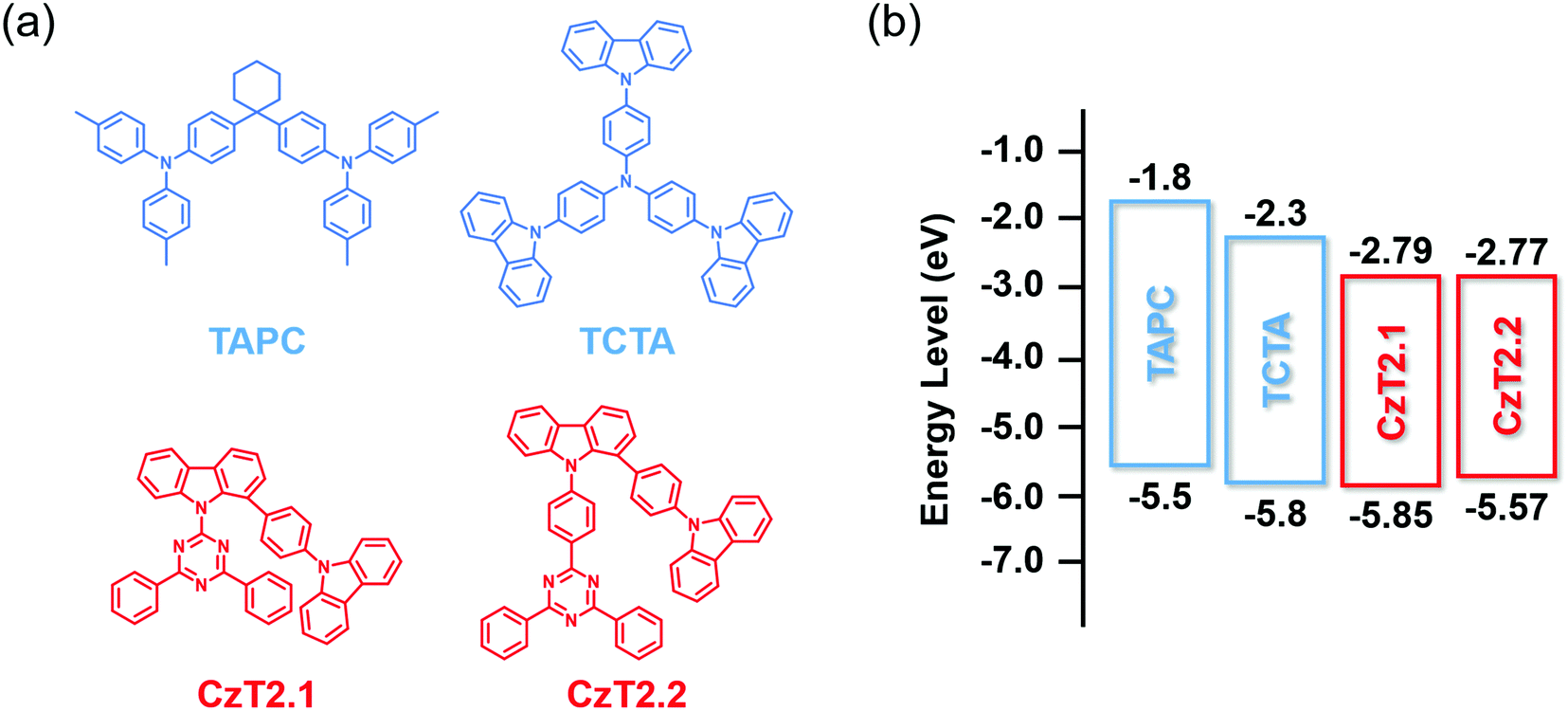 | ||
| Fig. 1 (a) Chemical structures of CzT2.1, CzT2.2, TAPC and TCTA. (b) The energy level alignments of these four compounds. | ||
Results & discussion
The photophysical characterization studies and electrochemical properties of CzT2.1 and CzT2.2 in solution as well as the corresponding energy levels are summarized in Table S2 (ESI†). The energy level alignments of the molecules studied in this work are shown in Fig. 1(b). Based on the energy levels of CzT2.1 and CzT2.2, two hole transport materials, TAPC and TCTA, were selected as the electron donors because both compounds possess molecular structures that could increase the probability of producing physically intermolecular interactions for the successful formation of exciplex.25,35,36 A fast-screening method was introduced to investigate exciplex formation by measuring the PL spectra of the D:A blends in a relatively high polarity solvent.37 Consequently, four D:A (1:1) blended samples, TAPC:CzT2.1, TCTA:CzT2.1, TAPC:CzT2.2, and TCTA:CzT2.2, were prepared and denoted as blend A1, A2, B1, and B2, respectively. The donor and acceptor materials were initially dissolved in tetrahydrofuran (THF), and then deionized (DI) water was added to the solution to give the colloidal solution. Fig. 2(a) shows the fluorescence photographs of A1, A2, B1, and B2 blends in THF with different water fractions under UV light (360 nm) illumination at room temperature. Apparently, the samples in THF with 90% water show the strongest emission, indicating the possibility of exciplex formation. The exciplex formation can be verified by comparing the PL spectral difference between the individual components and the colloidal solution. Fig. 2(b) shows the PL spectra of A1, A2, B1, and B2 blends measured in THF with 90% water together with the four corresponding blends dissolved in THF. As indicated, A1, A2, B1, and B2 blends showed broad spectral profiles with respective full width at half-maximum (FWHM) of 113, 107, 104, and 106 nm, together with emission peaks centered at 543, 516, 532, and 511 nm. Compared with the corresponding fluorescence of the constituted compounds, the PL spectra of the D:A colloidal solutions are red-shifted, implying the possibility of exciplex formation. In addition, the exciplex emission wavelengths are similar for the samples with the same donor (i.e., A1vs.B1 and A2vs.B2), indicating that the exciplex emission is mainly governed by the HOMO energy level of the donor while the LUMO energies of the acceptors CzT2.1 and CzT2.2 are similar.
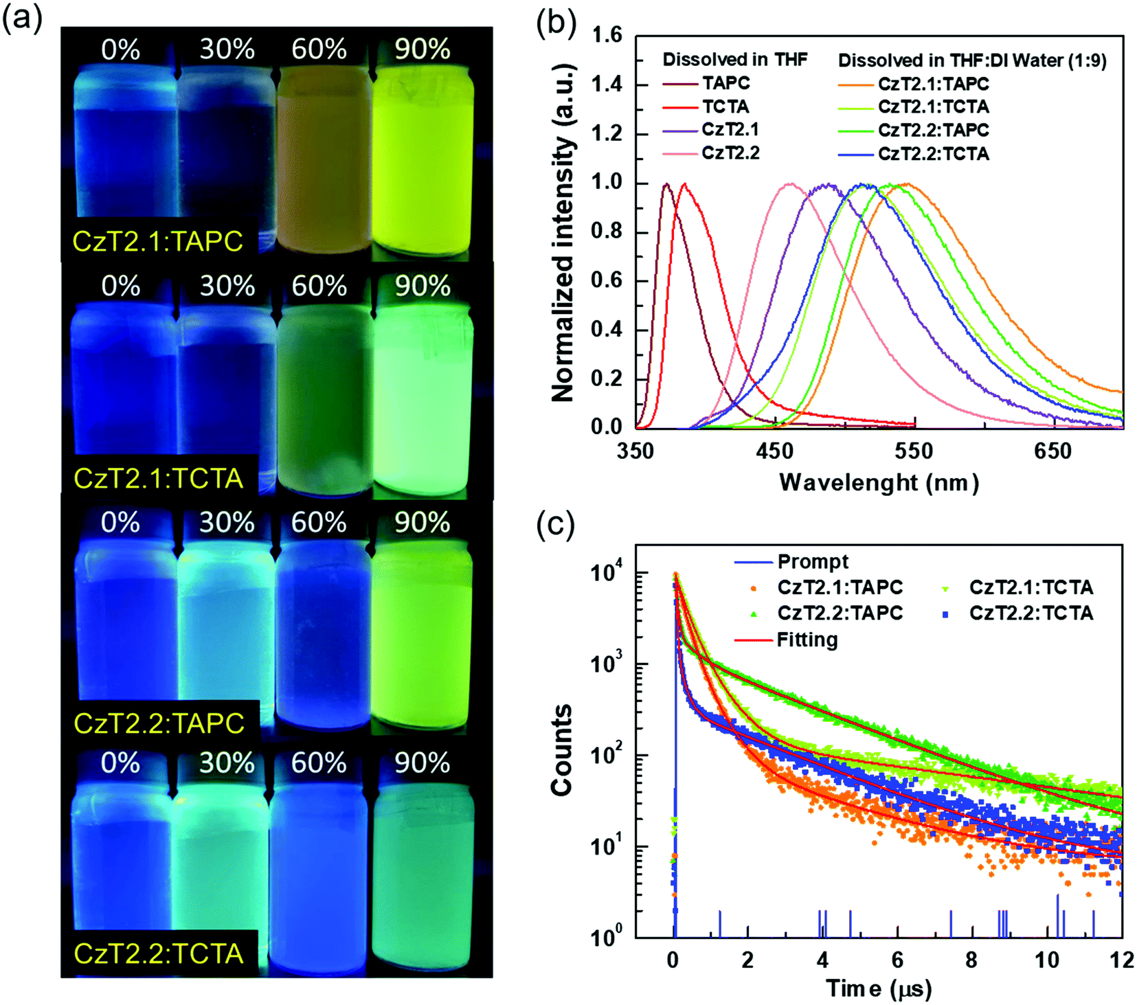 | ||
| Fig. 2 (a) Photographs of four exciplex samples in THF with different water fractions under UV light illumination at room temperature, (b) normalized PL spectra of the D and A in THF and D:A (1:1) blends in THF with 90% water, and (c) the transient PL profiles of the D:A (1:1) blends in THF with 90% water. | ||
Furthermore, the transient PL decays monitored at the emission peak were measured to study the exciplex formation in solution. Fig. 2(c) depicts the excited state decay characteristics of A1, A2, B1, and B2 blends measured at room temperature. These samples exhibit three-component decay profiles, which consist of two nanosecond components and a microsecond decay component (see Table S3 in the ESI†).38 The appearance of the delayed decay may suggest the existence of TADF behaviors for these colloidal solutions. However, these samples do not show typical bi-exponential decays observed in TADF exciplex systems. Therefore, a further examination must be conducted in order to delve into the relaxation mechanisms of the D:A blends.
In order to further corroborate the exciplex formation in the D:A blends, vacuum-deposited D:A blended films were fabricated to study the photodynamics in the solid state. The absorption and emission spectra of the four D:A blends, A1, A2, B1 and B2, with two distinct D:A ratios of 5:5 and 7:3 were respectively obtained. As depicted in Fig. 3, the absorption of the D:A blends can be regarded as the linear combination of the respective donors and acceptors, indicating no evident D/A interactions at the ground state. Compared with the emissions of donor and acceptor components, red-shifted emissions are observed for the D:A blends A1, A2 and B1, indicating the likelihood of exciplex formation upon photoexcitation. Among these D:A blends, A1 (5:5) displays the most red-shifted emission (530 nm), since it bears the smallest HOMO (D)–LUMO (A) energy gap (Fig. 1(b)), which is also in accordance with the exciplex-forming test in solution. However, due to the relatively limited red-shifted exciplex emissions, the possibility of the residual emissions contributed from the acceptor components cannot be fully excluded from the exciplex emissions. Regarding this point, a further examination must be conducted in order to clarify the sources of emissions from the D:A blends A1, A2 and B1. As for the TCTA:CzT2.2 (B2) blend, no apparent bathochromically shifted emission can be observed, since the blend film emission largely overlaps with that of the acceptor CzT2.2. The energy levels of CzT2.2 and TCTA are not in an ideal cascade alignment, which would give rise to an energy transfer type mechanism instead of exciplex formation. In addition, the B2 (7:3) blend film reveals that the emission profile perfectly overlaps with that of CzT2.2, thus the possibility of exciplex formation can be ruled out.
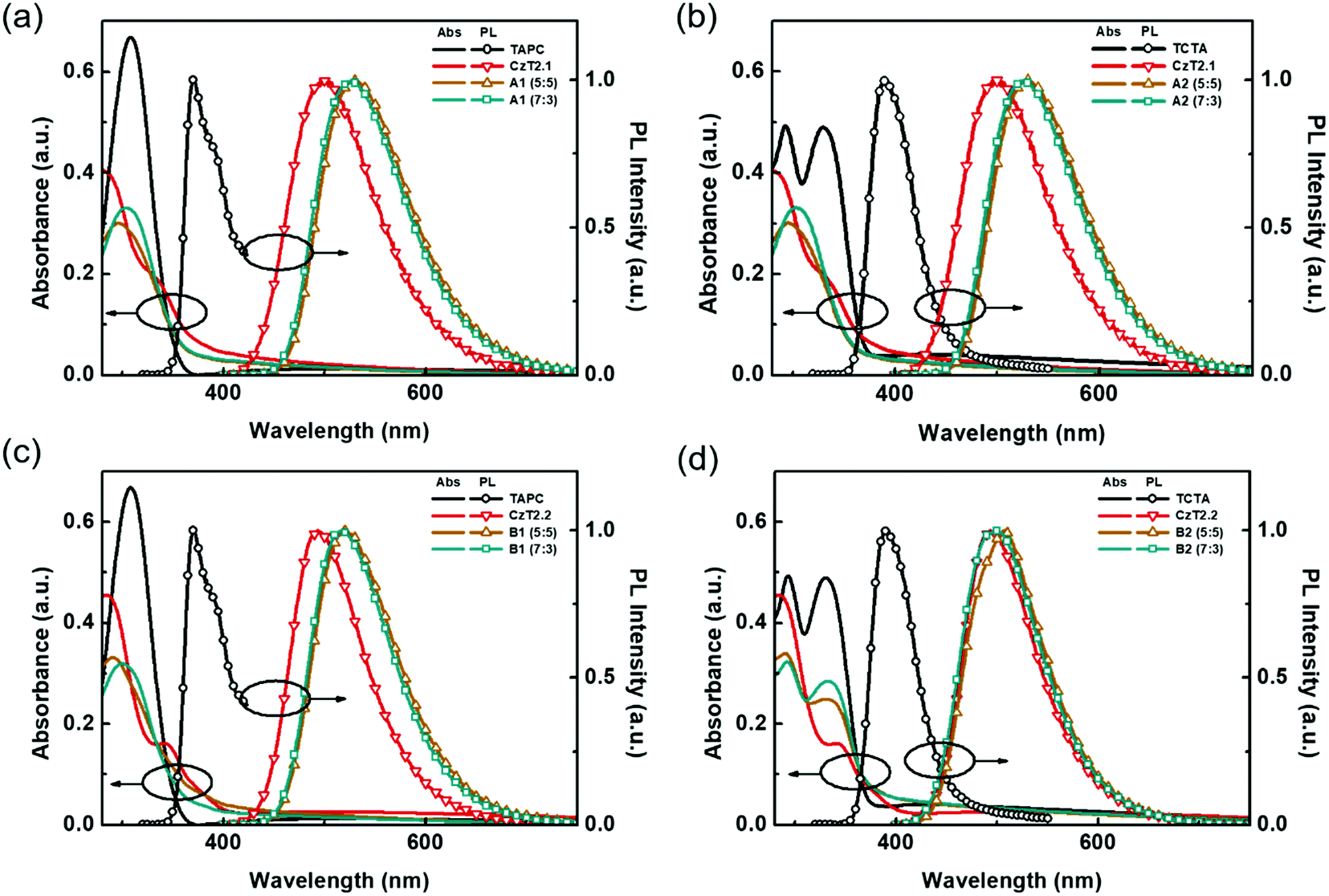 | ||
| Fig. 3 UV-Vis absorption and PL spectra of the respective donors, acceptors, and D:A blend films (a) A1, (b) A2, (c) B1, and (d) B2. | ||
Time-resolved photoluminescence (TRPL) measurements were then conducted to examine the relaxation behaviors of the excited state excitons. The transient relaxation profiles of the acceptor neat films as well as the D:A blend films are shown in Fig. 4, and the data are summarized in Table 1. For the acceptor pristine film, the transient relaxation profile can be fitted with two nanosecond decays and a microsecond delayed decay. The long-lived delayed fluorescence is attributed to the packing-induced intramolecular through-space charge transfer in the solid state, consistent with the timescales reported in previous findings.32 As for the exciplex-forming blends, the emission profiles can only be accurately fitted with tri-exponential decay models. This observation is different from the previously reported exciplex-based TADF systems, where bi-exponential decay models suffice to depict the relaxation mechanisms of the exciplexes.3,39,40 For the A1, A2 and B1 blends, we propose that the first (A1) component derives from the prompt fluorescence and the second (A2) component is attributed to the delayed fluorescence of exciplex. The third (A3) component is similar to the long relaxation time from the intramolecular through-space charge transfer state of the acceptor. Therefore, the partially overlapped emission spectra of the acceptor and D:A blend together with the presence of microsecond delayed fluorescence indicate that the exciplex emissions contain the residual emission of the acceptors. Interestingly, the observed A2 component at the sub-microsecond timescale is much shorter as compared to those of typical exciplex systems. Based on this observation, we propose a mechanism as shown in Fig. 4(c) to rationalize the relaxation profiles of the D:A blends (A1, A2 and B1). For the exciplex, the triplet excitons can be efficiently harvested through a close-lying acceptor 3LE state, leading to a short delayed emission lifetime of the exciplex. However, the 3LE state can also be shuttled to the 1CT state of the acceptor for giving emission. Therefore, the observed emissions of the D:A blends are contributed both from the exciplex and the bipolar acceptor. The proportion for each contribution hinges on the efficiency of exciplex formation as well as the relaxation behavior of the bipolar acceptor. On comparing the two acceptors, it has been observed that CzT2.2 possesses a smaller ΔEST and a shorter radiative decay lifetime than CzT2.1, giving a higher PLQY. As for the D:A blends with the stronger donor (TAPC), the A1 blend exhibits an apparent red-shifted emission with an increased PLQY as well as a smaller ΔEST as compared to those of the pristine acceptor film, signifying the efficient exciplex formation between the donor TAPC and the acceptor CzT2.1. In addition, the extended decay lifetimes for the sub-microsecond A1 and A2 components also arise from the typical delayed fluorescence characteristics of exciplex. In this case, the exciplex emission dominates the emission of the D:A blend mainly due to the inferior emissive character of CzT2.1. The emission characteristics and delay behaviors also reveal the efficient exciplex formation in the B1 blend. However, the higher ratio of the microsecond delay component (A3) implies the greater contribution from the intrinsic emission of CzT2.2. The inherent relaxation pathways of CzT2.2 compete with the exciplex formation through intermolecular charge transfer in the presence of the stronger donor (TAPC), leading to a slightly inferior PLQY as compared to that of the acceptor pristine film. Based on these observations, we could reasonably expect these two D:A blends to achieve good EQE performances in devices thanks to their high PLQYs.
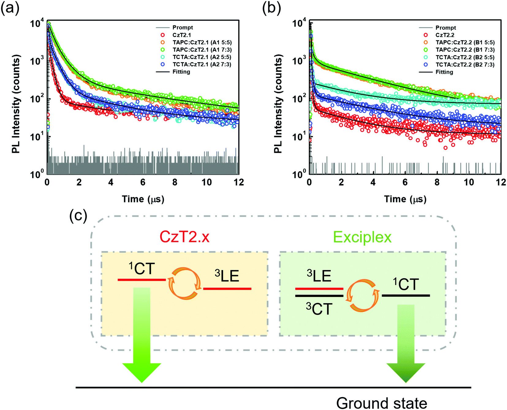 | ||
| Fig. 4 Time-resolved photoluminescence (TRPL) decay curves of (a) CzT2.1 neat film and A1, A2 blend films and (b) CzT2.2 neat film and B1, B2 blend films, and (c) schematic representation of the emission mechanisms of the D:A blends. | ||
| Sample | λ PL [nm] | PLQYb | E S [eV] | E T [eV] | ΔESTc [eV] | TRPLd | |||||
|---|---|---|---|---|---|---|---|---|---|---|---|
| A 1 | τ 1 [ns] | A 2 | τ 2 [ns] | A 3 | τ 3 [μs] | ||||||
|
a Maximum emission wavelength.
b Measured with an integrating sphere (Hamamatsu C9920-02).
c Estimated from the onsets of the photoluminescence spectra of the solid films, as shown in Fig. S1 and S2 (ESI).
d Measured under an ambient atmosphere, and the decay components were fitted with three exponential decay models as I(t) = A1exp(−t/τ1) + A2exp(−t/τ2) + A3 exp(−t/τ3).
|
|||||||||||
| CzT2.1 | 496 | 36 | 2.86 | 2.73 | 0.13 | 0.740 | 36 | 0.253 | 203 | 0.007 | 2.60 |
| CzT2.2 | 493 | 64 | 2.80 | 2.73 | 0.07 | 0.952 | 20 | 0.043 | 82 | 0.004 | 2.60 |
|
A1 (5:5) |
530 | 58 | 2.64 | 2.64 | 0.00 | 0.564 | 249 | 0.407 | 627 | 0.029 | 5.24 |
|
A1 (7:3) |
527 | 62 | 2.66 | 2.66 | 0.00 | 0.584 | 275 | 0.383 | 663 | 0.033 | 5.42 |
|
A2 (5:5) |
505 | 50 | 2.79 | 2.72 | 0.07 | 0.623 | 50 | 0.358 | 409 | 0.019 | 3.26 |
|
A2 (7:3) |
502 | 48 | 2.81 | 2.74 | 0.07 | 0.604 | 51 | 0.376 | 406 | 0.020 | 3.20 |
|
B1 (5:5) |
520 | 57 | 2.68 | 2.68 | 0.00 | 0.795 | 36 | 0.118 | 224 | 0.088 | 3.44 |
|
B1 (7:3) |
517 | 58 | 2.70 | 2.70 | 0.00 | 0.778 | 37 | 0.126 | 224 | 0.096 | 3.42 |
|
B2 (5:5) |
507 | 57 | 2.81 | 2.73 | 0.08 | 0.933 | 26 | 0.049 | 117 | 0.018 | 3.02 |
|
B2 (7:3) |
501 | 64 | 2.83 | 2.76 | 0.07 | 0.921 | 24 | 0.068 | 106 | 0.011 | 3.61 |
In the presence of a weaker donor (TCTA), blend A2 exhibits red-shifted emission as compared to pristine CzT2.1. However, a larger ΔEST (0.07 eV) is observed for A2 than A1, implying the weaker propensity of exciplex formation between TCTA and CzT2.1, leading to a reduced PLQY of the A2 blend. On the other hand, the emission components of the B2 blend closely resemble those of the pristine CzT2.2 film, even more conspicuous in the 7:3 blend. Thus, CzT2.2 can be regarded as a dopant dispersed in the TCTA host, where a complete energy transfer occurs, giving a PLQY of 64%, which is the same as the pristine CzT2.2 film despite a slight bathochromic shifted emission. This result indicates that the weaker donor (TCTA) cannot induce sufficient intermolecular charge transfer to give exciplex emission, leaving the intrinsic CzT2.2 emission. These results indicate that the trade-off between the self-emission of the acceptor and the emission of the exciplex can be manipulated by the donor strength and the emissive characters of bipolar acceptors, giving rise to diverse features in the D:A blended films.
Before device fabrication, atomic force microscopy (AFM) characterization studies of four (5:5) blends A1, A2, B1 and B2 were carried out to explore the morphologies of the blend films (see Fig. S3 in the ESI†). As a result, these blends exhibited a fairly smooth surface morphology with roughness ranging from 0.44 to 0.58 nm. There is no evident phase separation during the co-evaporation process, indicating that the D/A molecules are uniformly mixed. Accordingly, these D:A blended samples form amorphous characteristics and are suitable for serving as the exciplex-based EML of the devices.
For examining the A1, A2, B1 and B2 blends as the emitting layer of OLED devices, a simplified trilayer device architecture was adopted as ITO/TAPC (40 nm)/EML (20 nm)/TmPyPB (50 nm)/LiF (0.8 nm)/Al (120 nm). In this device configuration, TAPC and 1,3,5-tri[(3-pyridyl)-phen-3-yl]benzene (TmPyPB)41 are used as the hole transport layer (HTL) and the electron transport layer (ETL), respectively, because of their high carrier transport capabilities and high triplet energies. Fig. S4 (ESI†) shows the energy-level diagram of the devices. The D:A ratios were optimized (Fig. S5–S8, ESI†) for device A1d with TAPC:CzT2.1 (7:3), device A2d with TCTA:CzT2.1 (7:3), device B1d with TAPC:CzT2.2 (7:3), and device B2d with TCTA:CzT2.2 (5:5) as the EML to give the best EL performance.
Fig. 5 shows the EL characteristics of the green exciplex-based devices A1d, A2d, and B1d, and the TCTA-hosted CzT2.2 device B2d, while the pertinent data are summarized in Table 2. Fig. 5(a) shows the current density–luminance–voltage (J–V–L) curves of the devices. As indicated, given the similar HOMO energy levels of the materials, these devices exhibit a low turn-on voltage of about 2.5–2.6 V. In addition, the current densities of devices B1d and B2d exceed those of devices A1d and A2d, indicating the better carrier transport capability of CzT2.2. Fig. 5(b) depicts the normalized EL spectra of the devices recorded at a luminance of 1000 cd m−2. The respective EL emission peaks of devices A1d, A2d, B1d, and B2d were recorded at 537, 514, 514, and 514 nm, respectively, giving green to yellowish-green emissions as shown in the CIE coordinates (inset of Fig. 5(b)). Fig. 5(c and d) depict the device efficiencies. Both devices A1d and B1d used TAPC as the HTL as well as the donor in exciplex-based EML, eliminating the energy barrier between the HTL and EML. Thus, the hole can be directly injected into the EML from the HTL.42 In contrast, devices A2d and B2d used TCTA as the donor in the EML, generating a barrier between the HTL and EML. In addition to the carrier injection issue, the respective hole mobility of TCTA and TAPC is estimated to be about 3 × 10⁻⁴ cm2 V−1 s−1 and 1 × 10⁻² cm2 V−1 s−1.33,34 Compared with devices A1d and B1d, the much lower hole mobility of TCTA used in devices A2d and B2d would retard the hole transport and thus influence the carrier balance in the EML, rendering both devices A2d and B2d rather inefficient. The delayed fluorescence nature of exciplex could effectively recycle the triplet excitons to improve the device efficiency. The exciplex formation between TAPC and CzT2.1 for device A1d achieved a peak efficiency of 12.5% (39.2 cd A−1, 41.4 lm W−1), remaining as high as 12.5% (34.8 cd A−1, 39.1 lm W−1) at 100 cd m−2 owing to the fast decay lifetimes of the exciplex. Among these devices, device B1d exhibits the best peak efficiency of 15.0% (45.7 cd A−1, 50.0 lm W−1) and a slightly reduced efficiency of 14.3% (43.6 cd A−1, 45.0 lm W−1) at 100 cd m−2 due to the prolonged decay lifetimes of the emissive components. This result indicates that the emissions of acceptor CzT2.2 and the efficient exciplex-forming system cooperatively contribute to the overall device performance. In contrast, in addition to the carrier injection and transport issues, device A2d, employing the inferior exciplex-forming TCTA:CzT2.1 blend as the EML together with the less effective contribution from the intrinsic CzT2.1 emission, leads to device A2d displaying a peak efficiency of 9.6% (27.9 cd A−1, 29.1 lm W−1) and 7.8% (22.5 cd A−1, 20.1 lm W−1) at a high luminance of 100 cd m−2. It is worth noting that device B2d without the exciplex-forming system as the EML exhibits a peak efficiency of 11.7% (35.2 cd A−1 and 37.0 lm W−1), which is reduced to 9.8% (29.3 cd A−1 and 26.5 lm W−1) recorded at a high luminance of 100 cd m−2. As compared to device A2d, the higher EQE of device B2d results from the higher PLQY of CzT2.2, in which it acts as a TADF emitter dispersed in the TCTA-hosted EML.
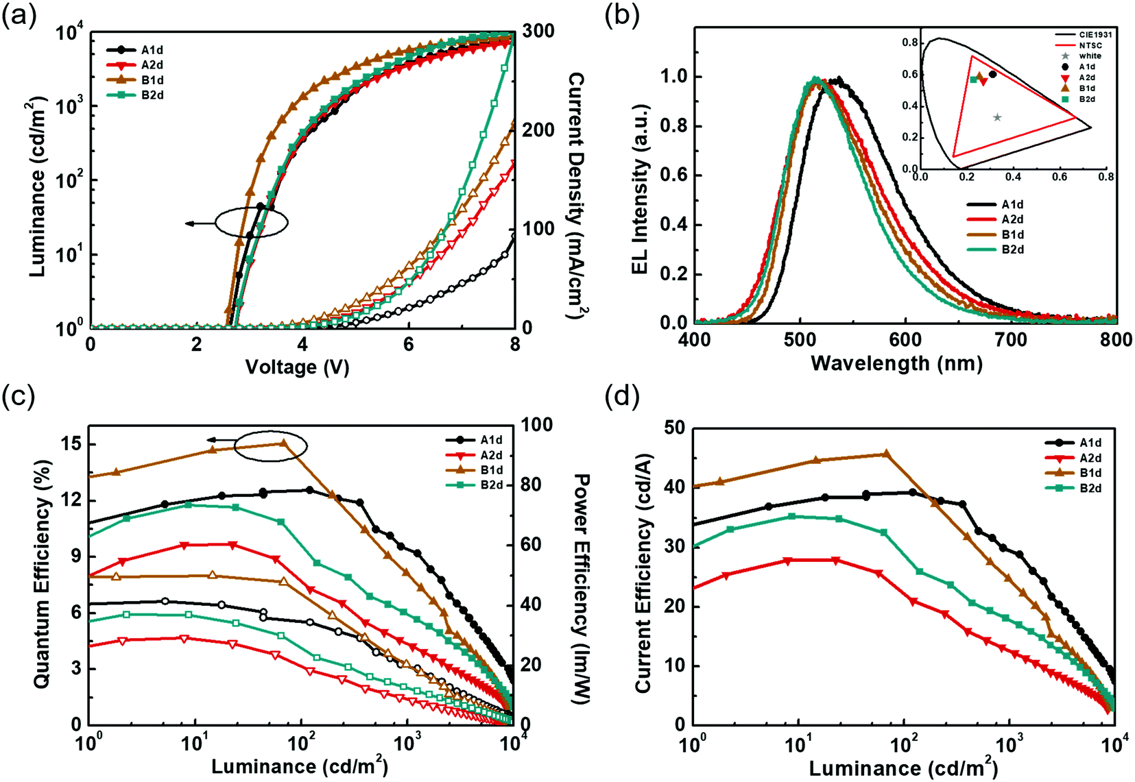 | ||
| Fig. 5 EL characteristics of the OLED devices with different D/A combinations: (a) current density–voltage–luminance (J–V–L) curves, (b) normalized EL spectra and (inset) the CIE coordinates, (c) EQE and power efficiency (PE) as a function of luminance, and (d) current efficiency (CE)–luminance diagram. | ||
| Device | D:A ratio |
V on [V] | L max at V [cd m−2 V−1] | Max. EQE/CE/PE [%/cd A−1/lm W−1] | EQE/CE/PEb [%/cd A−1/lm W−1] | λ max [nm] | CIEb [x,y] | CIEc [x,y] |
|---|---|---|---|---|---|---|---|---|
| a Measured at 1 cd m−2. b Measured at 102 cd m−2. c Measured at 103 cd m−2. | ||||||||
| A1d | 7:3 |
2.6 | 11406/10.8 |
12.5/39.2/41.4 | 12.5/34.8/39.1 | 537 | 0.31, 0.60 | 0.30, 0.60 |
| A2d | 7:3 |
2.6 | 8506/9.8 | 9.6/27.9/29.1 | 7.8/22.5/20.1 | 514 | 0.26, 0.56 | 0.25, 0.54 |
| B1d | 7:3 |
2.5 | 9305/9.0 | 15.0/45.7/50.0 | 14.3/43.6/45.0 | 514 | 0.25, 0.59 | 0.24, 0.58 |
| B2d | 5:5 |
2.6 | 9962/8.2 | 11.7/35.2/37.0 | 9.8/29.3/26.5 | 514 | 0.22, 0.56 | 0.21, 0.55 |
Conclusions
Two D–D′–A type bipolar molecules CzT2.1 and CzT2.2 were selected as electron acceptors to study the exciplex formation with electron donors TAPC and TCTA. Remarkably, four D:A blends exhibit two types of PL behaviors. The observed TRPL data indicate that the emissions of the D:A blends, including A1 (TAPC:CzT2.1), B1 (TAPC:CzT2.2), and A2 (TCTA:CzT2.2), are contributed from the TADF of the bipolar acceptors and the exciplex system. The exciplex dominates the emission of the A1 blend, whereas the B1 blend exhibits a more significant contribution from the intrinsic TADF emission of CzT2.2. Nevertheless, the green-emitting device A1d employing the A1 blend as the EML gives a maximum efficiency of 12.5% (39.2 cd A−1, 41.4 lm W−1), together with a low efficiency roll-off and an EQE of 12.5% (34.8 cd A−1, 39.1 lm W−1) at 100 cd m−2, owing to the fast decay lifetimes of the exciplex. Device B1d adopts the B1 blend as the EML which gives an even higher efficiency of 15.0% (45.7 cd A−1, 50.0 lm W−1), yet suffers a limited efficiency roll-off of 14.3% (43.6 cd A−1, 45.0 lm W−1) at 100 cd m−2 due to the prolonged exciton lifetimes of the B1 blend. As compared to the A1 blend, blend A2 (TCTA:CzT2.1) employing a weaker donor TCTA exhibits exciplex emission with a larger ΔEST (0.07 eV) together with the less emissive feature of CzT2.1, leading to a reduced PLQY and inferior device performance. On the other hand, the poor energy alignment between TCTA and CzT2.2 impedes the B2 blend (TAPC:CzT2.2) to give exciplex emission. Thus, CzT2.2 can be regarded as a dopant dispersed in the TCTA host, where a complete energy transfer occurs. This work highlights the benefits of incorporating emissive bipolar acceptors into the exciplex system that exhibits not only the expected exciplex emission but also the inherent acceptor TADF emission. The trade-off between the self-emission of the acceptor and the exciplex emission can be manipulated by the donor strength and the characters of emissive bipolar acceptors, giving rise to diverse features of the D:A blended films for enhancing the OLED device performance.Conflicts of interest
The authors declare no competing financial interests.Acknowledgements
The authors acknowledge financial support from the Ministry of Science and Technology (Grant No., MOST 107-2113-M-002-019-MY3, 110-2113-M-002-021, 110-2221-E-155-036, and 110-2221-E-155-033-MY2).References
- B. Minaev, G. Baryshnikov and H. Agren, Phys. Chem. Chem. Phys., 2014, 16, 1719–1758 RSC.
- C. Adachi, M. A. Baldo, M. E. Thompson and S. R. Forrest, J. Appl. Phys., 2001, 90, 5048–5051 CrossRef CAS.
- H. Uoyama, K. Goushi, K. Shizu, H. Nomura and C. Adachi, Nature, 2012, 492, 234–238 CrossRef CAS PubMed.
- K. Goushi, K. Yoshida, K. Sato and C. Adachi, Nat. Photonics, 2012, 6, 253–258 CrossRef CAS.
- Z. Yang, Z. Mao, Z. Xie, Y. Zhang, S. Liu, J. Zhao, J. Xu, Z. Chi and M. P. Aldred, Chem. Soc. Rev., 2017, 46, 915–1016 RSC.
- T. Hosokai, H. Matsuzaki, H. Nakanotani, K. Tokumaru, T. Tsutsui, A. Furube, K. Nasu, H. Nomura, M. Yahiro and C. Adachi, Sci. Adv., 2017, 3, e1603282 CrossRef PubMed.
- C.-C. Tsai, W.-C. Huang, H.-Y. Chih, Y.-C. Hsh, C.-W. Liao, C.-H. Lin, Y.-X. Kang, C.-H. Chang, Y. J. Chang and C.-W. Lu, Org. Electron., 2018, 63, 166–174 CrossRef CAS.
- Y.-S. Park, S. Lee, K.-H. Kim, S.-Y. Kim, J.-H. Lee and J.-J. Kim, Adv. Funct. Mater., 2013, 23, 4914–4920 CrossRef CAS.
- Y.-S. Park, W.-I. Jeong and J.-J. Kim, J. Appl. Phys., 2011, 110, 124519 CrossRef.
- N. Matsumoto, M. Nishiyama and C. Adachi, J. Phys. Chem. C, 2008, 112, 7735–7741 CrossRef CAS.
- K. Goushi and C. Adachi, Appl. Phys. Lett., 2012, 101, 023306 CrossRef.
- C.-K. Moon, J.-S. Huh, J.-M. Kim and J.-J. Kim, Chem. Mater., 2018, 30, 5648–5654 CrossRef CAS.
- V. Jankus, C.-J. Chiang, F. Dias and A. P. Monkman, Adv. Mater., 2013, 25, 1455–1459 CrossRef CAS PubMed.
- W.-Y. Hung, G.-C. Fang, S.-W. Lin, S.-H. Cheng, K.-T. Wong, T.-Y. Kuo and P.-T. Chou, Sci. Rep., 2014, 4, 5161 CrossRef CAS PubMed.
- W.-Y. Hung, T.-C. Wang, P.-Y. Chiang, B.-J. Peng and K.-T. Wong, ACS Appl. Mater. Interfaces, 2017, 9, 7355–7361 CrossRef CAS.
- M. Colella, A. Danos and A. P. Monkman, J. Phys. Chem. Lett., 2019, 10, 793–798 CrossRef CAS.
- F. Yan, R. Chen, H. Sun and X. W. Sun, Appl. Phys. Lett., 2014, 104, 153302 CrossRef.
- D. Graves, V. Jankus, F. B. Dias and A. Monkman, Adv. Funct. Mater., 2014, 24, 2343–2351 CrossRef CAS.
- M. Wang, T. Chatterjee, C. J. Foster, T. Wu, C.-L. Yi, H. Yu, K.-T. Wong and B. Hu, J. Mater. Chem. C, 2020, 8, 3395–3401 RSC.
- T.-L. Wu, S.-Y. Liao, P.-Y. Huang, Z.-S. Hong, M.-P. Huang, C.-C. Lin, M.-J. Cheng and C.-H. Cheng, ACS Appl. Mater. Interfaces, 2019, 11, 19294–19300 CrossRef CAS.
- T. B. Nguyen, H. Nakanotani, T. Hatakeyama and C. Adachi, Adv. Mater., 2020, 32, 1906614 CrossRef CAS.
- W. Liu, J.-X. Chen, C.-J. Zheng, K. Wang, D.-Y. Chen, F. Li, Y.-P. Dong, C.-S. Lee, X.-M. Ou and X.-H. Zhang, Adv. Funct. Mater., 2016, 26, 2002–2008 CrossRef CAS.
- D. Chen, Z. Wang, D. Wang, Y.-C. Wu, C.-C. Lo, A. Lien, Y. Cao and S.-J. Su, Org. Electron., 2015, 25, 79–84 CrossRef CAS.
- X.-K. Liu, Z. Chen, C.-J. Zheng, M. Chen, W. Liu, X.-H. Zhang and C.-S. Lee, Adv. Mater., 2015, 27, 2025–2030 CrossRef CAS PubMed.
- B. Liang, J. Wang, Z. Cheng, J. Wei and Y. Wang, J. Phys. Chem. Lett., 2019, 10, 2811–2816 CrossRef CAS PubMed.
- X.-K. Liu, Z. Chen, C.-J. Zheng, C.-L. Liu, C.-S. Lee, F. Li, X.-M. Ou and X.-H. Zhang, Adv. Mater., 2015, 27, 2378–2383 CrossRef CAS.
- M. Chapran, P. Pander, M. Vasylieva, G. Wiosna-Salyga, J. Ulanski, F. B. Dias and P. Data, ACS Appl. Mater. Interfaces, 2019, 11, 13460–13471 CrossRef CAS PubMed.
- M. Zhang, W. Liu, C.-J. Zheng, K. Wang, Y.-Z. Shi, X. Li, H. Lin, S.-L. Tao and X.-H. Zhang, Adv. Sci., 2019, 6, 1801938 CrossRef PubMed.
- J. Zhao, J. Ye, X. Du, C. Zheng, Z. He, H. Yang, M. Zhang, H. Lin and S. Tao, Chem. – Asian J., 2020, 15, 4093–4097 CrossRef CAS.
- H. J. Jang and J. Y. Lee, J. Phys. Chem. C, 2020, 124, 15057–15065 CrossRef CAS.
- N. Zhang, C. Zheng, Z. Chen, J. Zhao, M. Zhang, H. Yang, Z. He, X. Du and S. Tao, J. Mater. Chem. C, 2021, 9, 600–608 RSC.
- H. Miranda-Salinas, Y.-T. Hung, Y.-S. Chen, D. Luo, H.-C. Kao, C.-H. Chang, K.-T. Wong and A. Monkman, J. Mater. Chem. C, 2021, 9, 8819–8833 RSC.
- K. Goushi, R. Kwong, J. J. Brown, H. Sasabe and C. Adachi, J. Appl. Phys., 2004, 95, 7798–7802 CrossRef CAS.
- Y.-K. Chen, H.-H. Kuo, D. Luo, Y.-N. Lai, W.-C. Li, C.-H. Chang, D. Escudero, A. K. Y. Jen, L.-Y. Hsu and Y. Chi, Chem. Mater., 2019, 31, 6453–6464 CrossRef CAS.
- W. Song, H. L. Lee and J. Y. Lee, J. Mater. Chem. C, 2017, 5, 5923–5929 RSC.
- W.-Y. Hung, G.-C. Fang, Y.-C. Chang, T.-Y. Kuo, P.-T. Chou, S.-W. Lin and K.-T. Wong, ACS Appl. Mater. Interfaces, 2013, 5, 6826–6831 CrossRef CAS.
- D. Luo, C.-W. Liao, C.-H. Chang, C.-C. Tsai, C.-W. Lu, T. C. Chuang and H.-H. Chang, J. Phys. Chem. C, 2020, 124, 10175–10184 CrossRef CAS.
- T. Zhang, B. Chu, W. Li, Z. Su, Q. M. Peng, B. Zhao, Y. Luo, F. Jin, X. Yan, Y. Gao, H. Wu, F. Zhang, D. Fan and J. Wang, ACS Appl. Mater. Interfaces, 2014, 6, 11907–11914 CrossRef CAS.
- N. Haase, A. Danos, C. Pflumm, A. Morherr, P. Stachelek, A. Mekic, W. Brütting and A. P. Monkman, J. Phys. Chem. C, 2018, 122, 29173–29179 CrossRef CAS.
- M. Sarma and K.-T. Wong, ACS Appl. Mater. Interfaces, 2018, 10, 19279–19304 CrossRef CAS.
- S.-J. Su, T. Chiba, T. Takeda and J. Kido, Adv. Mater., 2008, 20, 2125–2130 CrossRef CAS.
- D. Luo, C.-T. Hsieh, Y.-P. Wang, T. C. Chuang, H.-H. Chang and C.-H. Chang, RSC Adv., 2018, 8, 30582–30588 RSC.
Footnotes |
| † Electronic supplementary information (ESI) available. See DOI: 10.1039/d1tc04700k |
| ‡ These authors contributed equally to this work. |
| This journal is © The Royal Society of Chemistry 2022 |