Development of a microfluidic dispensing device for multivariate data acquisition and application in molecularly imprinting hydrogel preparation

Yanawut Manmana a, Nobuyuki Hiraoka a, Toyohiro Naito ab, Takuya Kubo *a and Koji Otsuka a
aDepartment of Material Chemistry, Graduate School of Engineering, Kyoto University, Nishikyo-ku, Kyoto 615-8510, Japan
bDepartment of Applied Chemistry, Graduate School of Engineering, Kyushu University, Nishi-ku, Fukuoka 819-0395, Japan

Received 29th March 2022 , Accepted 20th May 2022

First published on 20th May 2022


Abstract

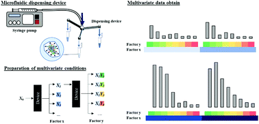
Molecularly imprinted polymers (MIPs) are superior materials with a molecular recognition ability that apply to various applications. In order to get high specificity recognition for target molecules, selecting polymerization conditions, which provide high interaction with the target template, is crucial. However, it requires time and labor to find the optimal polymerization composition, especially for large biomolecules. The advance in the microfluidic field enables researchers to control the flow rate and divide solutions based on the design of microfluidic devices for acquiring multivariate data by simultaneously preparing samples with different conditions. In this work, we fabricated microfluidic dispensing devices with different flow path widths that can give the solution of different flow rates. The accuracy of the flow rate was compared with the simulation value. As a result, the flow rate data showed almost the same data as the simulation value, and the dispensing volume ratio showed high reproducibility. Besides, the multivariate data from mixing the fluorescent molecule and protein solutions prepared by the dispensing device and a micropipette showed no significant difference with existing laboratory equipment. Finally, the dispensing device was used for preparing MIP hydrogels for lysozyme as a template protein. We successfully acquired multivariate data on the adsorption capacity of proteins, as a result, the hydrogels provided a high imprinting factor and adsorption specificity toward lysozymes.


1. Introduction

Molecular imprinting is one of the most important techniques for producing and designing materials that mimic natural receptors.1 The principle of imprinting is including template molecules with other polymer components during the synthesis process. When the templates were removed, cavities corresponding to the template size were generated inside the polymer network that provides specific recognition to the template.1 Recently, molecularly imprinted polymers (MIPs) have been widely studied and applied as artificial molecular recognition materials for selective adsorption and/or concentration of target compounds.2,3 The technique of MIPs has been applied to small molecules. Applications for macromolecules of biomolecules can lead to practical studies as the tools for artificially constructing antibodies and enzymes. On the other hand, there are only a few examples of the application of MIPs toward the biomolecules of proteins,4,5 viruses,6,7 and whole cells,8 and there are still some challenges to be solved. For example, we have to deal with problems such as (1) the instability of proteins in the polymerization solution, (2) the difficulty in the completion of the template removal, and (3) the nonspecific adsorption caused by the polymer backbone on the study of MIP targeting proteins.

To overcome the limitation of traditional MIPs, many novel techniques have been developed in recent years, such as emulsion polymerization,9 precipitation polymerization,10 and surface imprinting.11 Besides, incorporating MIP techniques with other types of materials, like metal-covalent organic frameworks,12,13 and magnetic nanoparticles,14,15 opens up a new possibility for improving MIP performance in various applications. MIPs based on hydrogels are one of the recent preparation techniques that have attracted attention for preparing the imprinting polymers of biomolecules. A hydrogel is a soft material with a loose polymer network that provides many advantages, such as stimulus responsiveness, permeability, elasticity, and water-absorbing properties.16 Hydrogels are used as separation membranes,17 biosensors,18,19 adsorbing materials,20,21 and drug delivery systems.22,23 Considering proteins as the templates, hydrogels show a better performance than rigid MIPs due to their properties, such as (1) higher protein stability since hydrogels contain fewer organic solvents than bulk MIPs, and (2) a flexible structure that allows macromolecules to penetrate and release. Several studies have been reported on the MIP hydrogel for proteins,24,25 such as polyacrylamide-based and poly(ethylene glycol) (PEG)-based cross-linker MIP hydrogels. In comparison with polyacrylamide and PEG, PEG is superior to polyacrylamide in biocompatibility and has low toxicity properties, which can be promising for application in the biological and medical fields. Our group26,27 and other researchers28–30 reported a number of MIP hydrogels, whereas there are still many problems in developing protein MIP hydrogels that need to be solved.

In order to obtain fine MIPs, optimization of MIP compositions is required. Since many chemical compositions are included in the polymerization process, a huge number of experiments need to be done to obtain the necessary data. These optimization processes require time, labor and expense. Here, microfluidics is the field in which the behavior of fluids on a small scale is studied and applied to multidisciplinary areas including engineering, physics, chemistry, biochemistry, nanotechnology, and biotechnology.31 We focus on the advantages of the microfluidic system over the macroscale analytical system, such as reducing the sample size and reagent consumption. Thus, it can be operated in an experiment with less energy and lower cost.31 Many microfluidic devices have been exploited in various biomedical,32 environmental,33 and pharmaceutical applications.34,35 Most of the microfluidic studies have been carried out using polydimethylsiloxane (PDMS),36 transparent and soft elastomers, as the substrate to fabricate the microfluidic system, and a lot of microfluidic designs have been developed.37,38 The versatility in design allows the microfluidic systems to mix and distribute solutions in difficult and complex systems, which reduces the time and labor of the experiments.

In this work, we fabricated a new microfluidic system that can offer solutions from a single inlet to multiple outlets at different distribution ratios. The microfluidic device was fabricated with PDMS as the substrates. We evaluated its distribution performance and reproducibility. Then, we demonstrated the possibility of using the device to obtain the multivariate data of the MIP hydrogel preparation for a target protein, lysozyme.

2. Materials and method

2.1 Chemicals and reagents

PEG 600 dimethacrylate (14G-DMA) was kindly donated from Shin-Nakamura Chemical (Wakayama, Japan) and utilized as received. Sylgard® 184 Silicone Elastomer Base (prepolymer) and curing agent were purchased from Dow Corning Toray (Tokyo, Japan). Fluoresbrite® Polychromatic Red Microspheres 1.0 μm (fluorescent microbeads) was from Polysciences Inc. (Warrington, PA, USA). S-CLEAN S-24 was from Sasaki Chemical (Kyoto, Japan). Lysozyme chloride was obtained from egg white, bovine serum albumin (BSA), sodium p-styrenesulfonate (SS), fluorescein, and 2,2′-azobis[2-(2-imidazolin-2-yl)propane] (AIYP) were from Wako Pure Chemical Industries (Osaka, Japan). 2-Acrylamido-2-methylpropane sulfonic acid (AMPS), sodium allylsulfonate (AS), and 8-anilino-1-naphthalenesulfonic acid (ANS) were from Tokyo Chemical Industry (Tokyo, Japan). Cytochrome c from an equine heart and trypsin from a bovine pancreas were from Sigma-Aldrich Japan (Tokyo, Japan) and other reagents were from Nacalai Tesque (Kyoto, Japan). All solvents were of analytical or HPLC grade.

2.2 Instruments

A laser direct drawing device DWL2000 model (Heidelberg Instruments, Germany) was used for patterning the chrome mask. A DELTA80 T3/VP SPEC-KU (SÜSS MicroTec SE, Germany) was used for spin coating the polymer. A KSC-150CBU (Kanamex, Kanagawa, Japan) was used for cleaning the wafer. The wafer and mask were aligned by a MA6 BSA SPEC-KU/3 (SÜSS MicroTec SE). The microfluidic pattern was checked and polymerized by an Olympus IX51 fluorescence microscope (Tokyo, Japan). An As One DO-300 (Osaka, Japan) was used for drying and baking at constant temperatures. A Thinky ARE–300 (Tokyo, Japan) was used for mixing and removing air bubbles in PDMS solution. A Cute-1MP (Femto Science, Gyeonggi, Korea) was used for the vacuum plasma process.

The solution in the dispensing device was transferred by a PHD ULTRA syringe pump (Harvard Apparatus, Holliston, MA, USA). The absorbance of the chemicals was measured using a UV-2450 (Shimadzu, Kyoto, Japan) as a UV-Vis spectrophotometer. The fluorescence was measured using a RF-5300PC (Shimadzu) as a fluorescence spectrometer. The absorbance and fluorescence were also measured using a SpectraMax iD3 plate reader (Molecular Devices, Tokyo, Japan). A Shimadzu Nexera X3 HPLC system was used for the measurement of proteins in the mixture solution.

2.3 Preparation of the microfluidic dispensing device

The structure and dimensions of a microfluidic channel were designed and drawn in the AutoCAD program. The picture of the design device used in this experiment and flow path structure are shown in Fig. 1. The SU-8 mold of the flow path pattern was drawn and developed on a chrome mask using a Direct-Write Laser System. After the pattern was developed, the chrome mask was carefully washed and dried with deionized (DI) water, acetone and finally cleaned with a mixing solution of sulfonic acid and hydrogen peroxide (ratio 5[thin space (1/6-em)]:[thin space (1/6-em)]1). Then, the SU-8 3050 photo-resist polymer was spin-coated on a silicon substrate, and the wafer was soft-baked at 65 °C and 95 °C for 5 and 10 min, respectively. The chrome mask was then installed with the silicon wafer and irradiated with UV light for polymerization. After polymerization, a post-exposer bake was done at 65 °C and 95 °C for 1 and 4 min, respectively. The SU-8 mold was further immersed in the developer for 3 min twice to remove uncured SU-8, soaked in isopropyl alcohol with shaking for 1 min, and then air-dried. Finally, the silicon substrate with trichloro (3,3,4,4,5,5,6,6,7,7,8,8,8-tridecafluorooctyl)silane was dropped on the surface, and the prepared SU-8 mold was put in a vacuum desiccator for 120 min.
image file: d2tb00685e-f1.tif
Fig. 1 The design of the dispensing device using AutoCAD software.

After the SU-8 mold was fabricated, a PDMS microfluidic dispensing device was made by mixing Sylgard® 184 silicone elastomer base and curing agent in a ratio of 10[thin space (1/6-em)]:[thin space (1/6-em)]1 (w/w). The PDMS mixing solution was stirred and defoamed with an ARE-300. Then, the PDMS mixing solution was spread on the SU-8 mold and allowed to stand in a vacuum desiccator until air bubbles in the PDMS solution disappeared. After heating the PDMS solution at 100 °C for 30 min, the PDMS was removed from the SU-8 mold. The holes were created at both ends of the microfluidic channel. Next, the PDMS was placed on the glass slide and treated with plasma to join the surface between the PDMS and a glass slide for 120 s. Finally, the PDMS and slide was heated at 100 °C for 10 min to connect the surface completely.

2.4 Evaluation of microfluidic dispensing devices

The flow rate near the discharge port of the microfluidic dispensing device was measured by using a syringe and a syringe pump. Fluorescent microbeads dispersed in DI water were sent to the dispensing device. A fluorescence microscope image was taken in the terminal region of the flow path using a digital camera. The moving distance of the fluorescent beads in a fixed frame was measured. The movement speed was calculated from the movement distance and the number of frames. The average movement speeds of 50 fluorescent beads were evaluated as the average flow velocity. The value obtained by multiplying the average flow velocity by the cross-sectional area of the flow path was assessed as the flow rate.

The actual dispensing volume of the device was evaluated by the following procedure. First, a certain amount of pure water was sent to the device using a syringe and a syringe pump. A constant concentration of fluorescein solution was diluted with DI water from each outlet. The dilution rate was calculated from the fluorescence intensity of the diluted fluorescein solution, and the amount of dispensed DI water was determined.

The reaction of ANS and BSA was used to compare the performance of the dispensing devices with a commercial micropipette. First, ANS and BSA with known concentrations were transferred to a microtube at different concentrations using a dispensing device or micropipette (Table 1) by controlling dispensing volume of ANS and BSA solution. After both ANS and BSA solutions were added to the microtube, the solution volume was adjusted and transferred to a 96-well plate for the fluorescence intensity measurement.

Table 1 Conditions of [ANS] and [BSA] mixing solution using both the dispensing device and a micropipette
ANS (μM) BSA (μM) ANS (μM) BSA (μM)
4.5 2.2 14.8 2.4
6.2 3.0 15.4 4.5
6.8 2.6 15.7 4.9
7.3 2.1 15.9 2.9
7.4 2.3 16.0 2.1
7.8 1.9 16.4 4.1
9.3 3.5 16.6 2.4
9.8 4.8 16.7 1.7
10.0 2.9 19.6 3.1
10.0 2.0 20.5 4.2
10.1 3.2 21.1 2.8
10.6 2.6 22.0 2.3
10.9 2.5 22.0 5.0
11.9 2.2 23.8 4.4
12.4 1.8 24.8 3.7
13.5 2.8 28.6 4.6
14.4 5.5 30.6 4.0
14.7 3.3 31.8 3.3


2.5 Preparation of the imprinted hydrogel using microfluidic dispensing devices

The MIP components, which include the cross-linker, functional monomer, template protein, and initiator, were dissolved in a solution. Then, these solutions with the variable parameters were transferred to a 200 μL-microtube using the microfluidic dispensing devices with the control volume while the other parameters were manually transferred with micropipettes (the composition of each component in all the gels is shown in Tables S1–S3, ESI). Then, the total volume of the polymerization solution was adjusted to 100 μL in each microtube with a micropipette. The polymerization composition was mixed and shaken for 30 min. Then, the mixing solution was put under a vacuum for degassing. The photopolymerization was carried out under 365 nm for 3 h. After polymerization, the hydrogel was washed for 24 h with a 1 M NaCl solution (Scheme 1). Non imprinted polymers (NIPs) were also prepared without any templates. After the preparation and washing, the hydrogels were directly used or stored no more than one week before the protein adsorption test.
image file: d2tb00685e-s1.tif
Scheme 1 Preparation of a protein imprinted hydrogel and protein adsorption procedures.

2.6 Batch adsorption test for proteins

The adsorption test for the prepared hydrogel was carried out using 20 μM protein solutions in 1.0 mM tris–HCl buffer pH 7.1 with 50 mM NaCl. The adsorbed amount of protein was estimated from the remaining concentration in the adsorption solution after 24 h at room temperature with a shaking apparatus. The adsorption ratio (AR) was defined as follows:
 
AR (%) = Padsorb/Ptheo × 100(1)
where Padsorb is the amount of adsorbed protein to the gels (w/v) and Ptheo is the theoretical amount of absorbable protein estimated from the preparation compositions. Here, the Ptheo of NIP was the same as that of MIP. Furthermore, the imprinting factor (IF) was calculated as follows:
 
IF = the amount of adsorbed protein toward MIP/the amount of adsorbed protein toward NIP(2)

3. Results and discussion

3.1 The fabrication and evaluation of microfluidic dispensing devices

After the fabrication process, the flow rate and actual discharge of the microfluidic dispensing device were evaluated. The flow rate of each flow path was also calculated by the simulation software (COMSOL Multiphysics 5.4, COMSOL, Stockholm, Sweden) to compare the accuracy in the fabrication process. The result shows that the flow rate ratio from the simulation and the experiment was almost the same at each outlet (Fig. 2(a)). Moreover, the result shows high reproducibility, indicating the reusability of the fabricated devices. However, the difference in the flow rate may vary the dispensing amount when dropping elution from the device to the container. This was due to the difference in measurement techniques. The flow rate was measured inside the dispensing device and the obtained data are similar to the simulation value while the dispensing volume was measured after the solution release from the outlet. Therefore, the flow rate on dropping elution from the device to the container might be slightly changed, and result in a difference in the actual dispensing amount. As a result, the fabrication process and the application of the microfluidic dispensed the solutions with sufficient distribution ratios to realize different conditions simultaneously.
image file: d2tb00685e-f2.tif
Fig. 2 (a) Ratio of outflow rate or volume by each outlet from the dispensing device from the simulation (sim.) and experimental data (expt.). (b) Fluorescence intensity of ANS using the dispensing device and a micropipette to transfer the solution. The mixing condition of ANS and BSA is shown in Table 1.

To acquire multivariate data, the performance of microfluidic dispensing devices was also compared with that of a commercially available pipette by using the fluorescence reaction between ANS and BSA. Since the fluorescence intensity was affected by both the concentrations of ANS and BSA,39,40 the multi-data result was obtained by varying both ANS and BSA concentrations, as shown in Table 1. The results of the dispensing device and micropipette results showed no significant difference at a 95% confidence interval (Fig. 2(b)). This result indicates the possibility to use these devices to transfer the solution with the same performance as a micropipette but with less labor and time to operate more complex conditions.

3.2 Optimization conditions for lysozyme MIP hydrogel polymerization using microfluidic dispensing devices

In order to demonstrate the application of dispensing devices, multivariate data on the polymerization solution composition of the MIP hydrogel was acquired. The compositions of polymerization solution are known to affect the adsorption performance. Therefore, the hydrogels prepared with different monomer concentrations, amount of initiator, and types of monomers were investigated. Lysozyme was used as a template protein in this study.
3.2.1 The effect of initiator and monomer and their relationship. In the first multivariate study, the hydrogels with different AIYP/14G (wt%) (0.58–6.75) and AMPS/lysozyme molar ratios (5.07–22.9) were synthesized. The results showed that the adsorption on MIP hydrogels increased when the ratio of AMPS/lysozyme increased from 5.07 to 22.9 (Fig. 3). This explains that hydrogels with more functional monomers have a strong electrostatic interaction with the protein. Whereas, the adsorption on MIP hydrogels gradually decreased as the AIYP/14G ratio increased. This tendency indicates that large molecules were hampered from permeating into hydrogels because the cross-link increased by associating with the increase of AIYP, and it led to a decrease in the polymerized chain length. Hence, using a relatively small amount of initiator is important to let proteins smoothly permeate into hydrogels. Consequently, we can obtain a higher adsorbed amount and adsorption selectivity. When the regression equation is structured by using surface methodology regarding the relation between AIYP ratio toward cross-linking agents (wt%), the AMPS ratio toward proteins and the adsorption rate, each rate is considered as a dependent variable, and the determination coefficient is indicated as R2 = 0.827 which can be calculated according to following equation:
 
y = 0.98x12 − 6.70x1 − 0.22x1x2 + 1.25x2 + 6.53(3)
where y is the adsorption rate, x1 is the amount of AIYP for the cross-linking agent (wt%), and x2 is the molar ratio of AMPS to the protein.

image file: d2tb00685e-f3.tif
Fig. 3 Adsorption rate of lysozyme in each lysozyme MIP and NIP hydrogels prepared with different AIYP/14G and AMPS/lysozyme ratios. The concentrations of lysozyme and 14G for every hydrogel in the preparation process were 0.38 mM and 80.6 mM, respectively. Adsorption condition: gel size, 100 μL; solution volume, 2.5 mL; concentration of lysozyme, 0.02 mM; concentration of NaCl, 50 mM; solvent, 1.0 mM tris–HCl buffer (pH 7.1).

The equation shows that the amount of AIYP gives a negative effect, while the molar ratio of AMPS toward the protein can provide a positive effect on lysozyme adsorption. Besides, the dependence effect of AMPS on the amount of AIYP can be observed by the equation.

3.2.2 The effect of types of sulfonate monomers. We also investigated the preparation of MIP hydrogels using different sulfonated monomers (AMPS, AS, and SS) (Scheme 1). The investigation implies that these different monomers may have different electrostatic interactions with lysozyme depending on each different structure. Then, we prepared the hydrogel with three sulfonated monomers and the hydrogel combined with two different sulfonated monomers. Furthermore, the synthesis of hydrogels with the different amounts of AIYP was conducted at the same time (2.5% for gels #33-56 and 1.0% for gels #57–77). The hydrogel with two sulfonate monomers showed a higher IF than the hydrogel with one simple sulfonate monomer indicating IF which was approximately 1 as described in Table S2, ESI (Fig. 4(a)). Especially when using AMPS and SS, we confirmed that they tended to show a higher IF than other combinations.
image file: d2tb00685e-f4.tif
Fig. 4 (a) and (b) Adsorption rate of lysozyme in each lysozyme MIP and NIP gel prepared with different combinations of sulfonate monomers. The concentrations of lysozyme, 14G, and AIYP in every hydrogel in the preparation process were 0.38 mM, 80.6 mM, 2.5 wt% (#33–56) or 1.0 wt% (#57–77) vs. 14G, respectively. Adsorption condition: gel size, 100 μL; solution volume, 2.5 mL; concentration of lysozyme, 0.02 mM; concentration of NaCl, 50 mM; solvent, 1.0 mM tris–HCl buffer (pH 7.1).

Interestingly, as shown in Table S3, ESI (Fig. 4(b)), we observed a different trend when altering the AIYP proportion to 1.0 wt%. Regarding AMPS and SS, a higher adsorption was found even though they were one sulfonated monomer. On the basis of these results, we constructed the regression equation. Consequently, the determination coefficient R2 = 0.967 and the following high correlativity equation were obtained:

 
y = 1.03x2 − 0.09x2x3 − 0.1x2x4 + 2.45x3 − 0.16x3x4 + 4.16(4)
where y is the adsorption rate, and x2x3x4 are the molar ratios toward proteins of AMPS, SS and AS, respectively. According to these results, SS is presumed to contribute to the most effective adsorption.

SS is the only monomer with an aromatic ring, considering each construction of monomers. In addition to the electrostatic interactions, we can conclude that the aromatic ring of SS interacts with the hydrophobic region inside of each lysozyme.

Through these results, we successfully realized the simple optimization of synthetic MIPs by using the microfluidic dispensing device. From both Sections 3.2.1 and 3.2.2, we can see that the effect of the amount of initiator, ratio of template/functional monomers, and types of sulfonate monomer can affect the adsorption performance. However, the single equation that combine all of these parameters cannot be obtained from these data sets, as seen in the Fig. 4, changing only one parameter can lead to a different adsorption behaviour of the other parameters. To make the single equation possible, larger data sets need to be used while using only microfluidic dispensing devices to vary these parameters which is impossible due to the amount of laborious study required. Therefore, other high-throughput instruments that can reduce work on other processes would provide the data for better understanding MIPs and need to be developed.

3.2.3 Selectivity of MIP toward lysozyme. After obtaining the adsorption data by varying the condition of MIP polymerization solutions, MIP hydrogels were further used for testing the specificity toward lysozyme with the other proteins. First, the performance of lysozyme adsorption was compared with trypsin adsorption in the single protein adsorption (Fig. S1, ESI). It was found that all MIP hydrogels can adsorb trypsin lower than 15%, which was lower than lysozyme adsorption in most conditions except for MIP hydrogels prepared with low ratios of sulfonate monomer (gels #1–16) or a high amount of AIYP (gels #22–24, 30–32). Moreover, the MIP hydrogel was used for the adsorption test in the lysozyme mixing solution with cytochrome c and BSA to study the selectivity in mixing conditions (trypsin cannot be performed in this condition due to the degradation effect when mixing with other proteins). The result from the MIP hydrogel #37 as the example showed that the MIP hydrogel has higher specificity toward lysozyme than the other two proteins at all initial concentrations (Fig. 5). Furthermore, these results showed that the MIP composition highly specific to lysozyme protein was successfully obtained by using dispensing devices to acquire multivariate data.
image file: d2tb00685e-f5.tif
Fig. 5 (a) Chromatograms of the standard protein solution, after immersing in NIP and MIP at 0.01 mM of each protein concentration. (b) Adsorption performance of #37 MIP and NIP in the mixing protein solution at different initial concentrations. Adsorption condition: gel size, 100 μL; solution volume, 2.5 mL; concentration of proteins, 0.002–0.02 mM; concentration of NaCl, 50 mM; solvent, 1.0 mM tris–HCl buffer (pH 7.1). The abbreviation for proteins; Cyc = cytochrome c, Lyz = lysozyme, and BSA = Bovine serum albumin.

4. Conclusions

In this work, we successfully developed microfluidic devices that can transfer solutions with different flow rates to acquire multivariate data. The performance of the fabricated devices was evaluated by comparing experimental data with the simulation value. This confirmed that the experimental data obtained from the devices could distribute solutions at almost the same flow rate ratio as the simulation result. We also evaluated the amount of dispensed liquid, and the result confirmed that it could be distributed with high reproducibility. The performance of the dispensing device was also compared with a commercially available pipette for transferring solution to acquire multivariate data between the reaction of ANS and BSA. The result shows no significant difference in the fluorescence intensity of the data obtained from dispensing devices and a micropipette, demonstrating the use of dispensing devices to get complex data with less labor and time to vary the variation condition.

Finally, we demonstrated the use of the dispensing device for preparing the MIP hydrogel by varying the polymerization solution composition for the lysozyme imprinted hydrogels. This showed that each polymerization component could affect the adsorption performance differently. Besides, the hydrogel with high specificity adsorption toward lysozyme was obtained. These results show the possibility to acquire multivariate data using the dispensing device for the analysis and consideration of optimization conditions by simultaneously preparing samples under the different conditions.

Even though the microfluidic dispensing device can reduce the time for the MIP hydrogel preparation step, processes that are time and labor intensive still remain. Therefore, we hope that other high-throughput instruments to utilize MIP research will be developed in the future.

Author contributions

Y. Manmana, T. Naito and N. Hiraoka: conceptualization, methodology, validation, investigation. T. Kubo: conceptualization, supervision, project administration. K. Otsuka: visualization, project administration.

Conflicts of interest

There are no conflicts to declare.

Acknowledgements

This study was partly supported by the Adaptable and Seamless Technology transfer Program through Target-driven R&D (A-STEP) from Japan Science and Technology Agency (JST) Grant Number JPMJTR214C and JSPS KAKENHI Grant Number 20K20567.

References

  1. H. R. Culver and N. A. Peppas, Chem. Mater., 2017, 29, 5753–5761 CrossRef CAS.
  2. X. Li and S. M. Husson, Biosens. Bioelectron., 2006, 22, 336–348 CrossRef CAS PubMed.
  3. M. Cantarella, S. C. Carroccio, S. Dattilo, R. Avolio, R. Castaldo, C. Puglisi and V. Privitera, Chem. Eng. J., 2019, 367, 180–188 CrossRef CAS.
  4. T. Matsunaga and T. Takeuchi, Chem. Lett., 2006, 35, 1030–1031 CrossRef CAS.
  5. T. Takeuchi, D. Goto and H. Shinmori, Analyst, 2007, 132, 101–103 RSC.
  6. M. Jenik, R. Schirhagl, C. Schirk, O. Hayden, P. Lieberzeit, D. Blaas, G. Paul and F. L. Dickert, Anal. Chem., 2009, 81, 5320–5326 CrossRef CAS.
  7. Z. Altintas, J. Pocock, K. A. Thompson and I. E. Tothill, Biosens. Bioelectron., 2015, 74, 996–1004 CrossRef CAS PubMed.
  8. J. Zhang, Y. Wang and X. Lu, Anal. Bioanal. Chem., 2021, 413, 4581–4598 CrossRef CAS PubMed.
  9. G. Zhao, J. Liu, M. Liu, X. Han, Y. Peng, X. Tian, J. Liu and S. Zhang, Appl. Sci., 2020, 10, 2868 CrossRef CAS.
  10. Y. Lu, Y. Zhu, Y. Zhang and K. Wang, J. Chem. Eng. Data, 2019, 64, 1045–1050 CrossRef CAS.
  11. C. Dong, H. Shi, Y. Han, Y. Yang, R. Wang and J. Men, Eur. Polym. J., 2021, 145, 110231 CrossRef CAS.
  12. Z. Guo, A. Florea, M. Jiang, Y. Mei, W. Zhang, A. Zhang, R. Săndulescu and N. Jaffrezic-Renault, Coatings, 2016, 6, 42 CrossRef.
  13. K. Qian, G. Fang and S. Wang, Chem. Commun., 2011, 47, 10118–10120 RSC.
  14. S. Ansari and M. Karimi, Talanta, 2017, 167, 470–485 CrossRef CAS PubMed.
  15. N. Sanadgol and J. Wackerlig, Pharmaceutics, 2020, 12, 1–31 CrossRef PubMed.
  16. M. K. Yazdi, V. Vatanpour, A. Taghizadeh, M. Taghizadeh, M. R. Ganjali, M. T. Munir, S. Habibzadeh, M. R. Saeb and M. Ghaedi, Mater. Sci. Eng., C, 2020, 114, 111023 CrossRef CAS.
  17. N. Alele and M. Ulbricht, Sep. Purif. Technol., 2016, 158, 171–182 CrossRef CAS.
  18. C. Cheubong, A. Yoshida, Y. Mizukawa, N. Hayakawa, M. Takai, T. Morishita, Y. Kitayama, H. Sunayama and T. Takeuchi, Anal. Chem., 2020, 92, 6401–6407 CrossRef CAS PubMed.
  19. C. Wang, A. Javadi, M. Ghaffari and S. Gong, Biomaterials, 2010, 31, 4944–4951 CrossRef CAS PubMed.
  20. G. Jing, L. Wang, H. Yu, W. A. Amer and L. Zhang, Colloids Surf., A, 2013, 416, 86–94 CrossRef.
  21. V. Van Tran, D. Park and Y.-C. Lee, Environ. Sci. Pollut. Res., 2018, 25, 24569–24599 CrossRef CAS PubMed.
  22. L. Scrivano, O. I. Parisi, D. Iacopetta, M. Ruffo, J. Ceramella, M. S. Sinicropi and F. Puoci, Polym. Adv. Technol., 2019, 30, 743–748 CrossRef CAS.
  23. N. Mortensen, P. Toews and J. Bates, Polymers, 2022, 14, 248 CrossRef CAS PubMed.
  24. A. K. Venkataraman, J. R. Clegg and N. A. Peppas, J. Mater. Chem. B, 2020, 8, 7685–7695 RSC.
  25. M. Qi, K. Zhao, Q. Bao, P. Pan, Y. Zhao, Z. Yang, H. Wang and J. Wei, Polymers, 2019, 11, 622 CrossRef.
  26. T. Kubo, S. Arimura, Y. Tominaga, T. Naito, K. Hosoya and K. Otsuka, Macromolecules, 2015, 48, 4081–4087 CrossRef CAS.
  27. T. Kubo, S. Arimura, T. Naito, T. Sano and K. Otsuka, Anal. Sci., 2017, 33, 1311–1315 CrossRef CAS PubMed.
  28. T. Morishita, A. Yoshida, N. Hayakawa, K. Kiguchi, C. Cheubong, H. Sunayama, Y. Kitayama and T. Takeuchi, Langmuir, 2020, 36, 10674–10682 CrossRef CAS PubMed.
  29. N. Adrus and M. Ulbricht, Polymer, 2012, 53, 4359–4366 CrossRef CAS.
  30. S. M. Reddy, G. Sette and Q. Phan, Electrochim. Acta, 2011, 56, 9203–9208 CAS.
  31. G. M. Whitesides, Nature, 2006, 442, 368–373 CrossRef CAS PubMed.
  32. A. Perestrelo, A. Águas, A. Rainer and G. Forte, Sensors, 2015, 15, 31142–31170 CrossRef PubMed.
  33. H. F. Li and J. M. Lin, Anal. Bioanal. Chem., 2009, 393, 555–567 CrossRef CAS PubMed.
  34. J. B. Lee and J. H. Sung, Biotechnol. J., 2013, 8, 1258–1266 CrossRef CAS PubMed.
  35. M.-H. Wu, S.-B. Huang and G.-B. Lee, Lab Chip, 2010, 10, 939 RSC.
  36. J. M.-K. Ng, I. Gitlin, A. D. Stroock and G. M. Whitesides, Electrophoresis, 2002, 23, 3461–3473 CrossRef CAS.
  37. P. C. Chen, Y. C. Chen and C. M. Tsai, Microelectron. Eng., 2016, 150, 57–63 CrossRef CAS.
  38. Y. Chen, W. Sun, P. Luo, M. Zhang, Y. Wang, H. Zhang and P. Hu, Sens. Actuators, B, 2019, 283, 247–254 CrossRef CAS.
  39. O. K. Gasymov and B. J. Glasgow, Biochim. Biophys. Acta, Proteins Proteomics, 2007, 1774, 403–411 CrossRef CAS PubMed.
  40. C. G. Rosen and G. Weber, Biochemistry, 1969, 8, 3915–3920 CrossRef CAS PubMed.

Footnote

Electronic supplementary information (ESI) available. See DOI: https://doi.org/10.1039/d2tb00685e

This journal is © The Royal Society of Chemistry 2022