
Bioinspired photo-responsive membrane enhanced with “light-cleaning” feature for controlled molecule release†
Qisheng
Ye
ab,
Rui
Wang
ab,
Saitao
Yan
ab,
Baoliang
Chen
 ab and
Xiaoying
Zhu
*ab
ab and
Xiaoying
Zhu
*ab
aDepartment of Environmental Science, Zhejiang University, Hangzhou, Zhejiang 310058, China. E-mail: zhux@zju.edu.cn; qsye@zju.edu.cn; ruiw@zju.edu.cn; yansaitao@zju.edu.cn; blchen@zju.edu.cn; Fax: +86-571-88982651; Tel: +86-571-88982651
bZhejiang Provincial Key Laboratory of Organic Pollution Process and Control, Hangzhou 310058, China
First published on 23rd December 2021
Abstract
Inspired by the stomatal feature of plant leaves, a photo-responsive membrane was developed to enhance the removal of irreversible membrane fouling and to control molecule release. Photo-responsive polymers were prepared by reacting the amine group of 4-amineazobenzene with about 3, 5 and 9 out of 12 carboxylic groups of PMAA which was grafted from P(VDF-CTFE) with a certain length. Subsequently, high-flux photo-responsive membranes (PRMs) were prepared from the heterogeneous polymers with different contents of photo-switchable azobenzene following a non-solvent-induced phase-inversion protocol. The pore size and surface hydrophilicity of PRMs could be reversibly increased by switching visible light to UV irradiation, which dramatically enhanced the backflushing efficiency on PRMs under UV irradiation. The “light-cleaning” process could recover more than 90% of the irreversible flux decline caused by typical organic foulant (BSA) and biological foulant (E. coli) on PRMs. The higher the content of azobenzene, the more obvious the pore size and hydrophilicity variation after light switching but the smaller the absolute pore size observed for PRMs. On the other hand, the light-switching gates of PRMs enabled the controlled release of molecules with different sizes. The novel PRM provided an efficient solution to mitigate irreversible membrane fouling and a light-triggered molecule release protocol, which would improve the membrane performance and further expand the application field of the membrane.
1. Introduction
A membrane is an important separation tool widely used in water purification,1 as well as in food and pharmaceutical industries.2,3 On the other hand, membranes provide a new option of controlled release of drugs in the biomedical field.4,5 However, conventional membranes usually suffer from the problems of permeability/selectivity trade-off6 and membrane fouling.7–9Membranes tailored with specific properties such as sophisticated structures, hierarchical organizations, controlled selectivity, and antifouling or self-cleaning properties inspired by nature are called bioinspired membranes.10 Especially, the controlled selectivity of bioinspired membranes could be a solution to address the trade-off between selectivity and permeability of conventional membranes. For example, natural aquaporins11 and artificial water channels12,13 imbedded in membranes would increase the water permeability. However, it is a challenge to maintain the activity of aquaporins during membrane fabrication and application; in addition, preparation of artificial water channels in membranes is usually tedious and costly, which is difficult to scale up for practical applications in the current state. On the other hand, the pore size of some bioinspired membranes can respond to environmental stimuli, which enables the variation of membrane selectivity in different scenarios to address the permeability/selectivity trade-off from another aspect. For example, inspired by the stomatal closure feature of plant leaves at relatively high temperature, a membrane composed of poly(N-isopropylacrylamide) covalently bound to graphene oxide (GO) was able to control molecule release according to the environmental temperature;14 in addition, a membrane containing poly(vinylidene fluoride)-g-poly(N-isopropylacrylamide) and GO nanosheets converted photoirradiation into temperature variation which enabled pore size shifting.15 As compared with temperature, light is a more attractive trigger for responsive materials due to its speedy and non-invasive nature as well as the potential to reduce energy costs significantly. Even though photo-responsive groups such as azobenzene and spiropyran have been widely used to prepare composites for light-triggered functions,16 only very limited works have been reported studying the membrane pore size or selectivity variation triggered by light switching. For example, a photoresponsive membrane surface was developed through UV grafting of photoresponsive spiropyran molecules onto a PES UF membrane.17 However, the surface-initiated polymerization protocol would dramatically reduce the membrane permeability. In another study, azobenzene and β-cyclodextrin were used to modify PES which was subsequently blended with bulk PES to prepare photoresponsive membranes.18 Nevertheless, the complicated composite membrane was difficult to prepare and may suffer the problem of membrane fouling.
Membrane fouling is inevitable for most membrane separation processes; moreover, irreversible membrane fouling is another crucial issue needed to be solved in the field of membrane technology.19,20 Nature also provides hints to address the membrane fouling problem from different aspects. Superhydrophobicity/non-wetting is an essential property of typical self-cleaning biological surfaces.21–24 Inspired by natural self-cleaning biological surfaces, hybrid micro-/nanostructures were constructed on a commercial polypropylene membrane, which endowed the membrane with significantly prolonged fouling induction time because of the superior hydrophobicity.25 In another study, mussel-inspired dopamine was combined with bacterial cellulose and GO nanosheets to fabricate a highly hydrophilic antifouling membrane.26 However, membranes modified with specific static physical and chemical surface properties which would not self-adjust with environmental conditions might have limited antifouling performances to some extent.
In this study, a novel photoresponsive membrane inspired by the stomatal feature of plant leaves was developed to control molecule release and enhance the removal of irreversible membrane fouling. Photoresponsive polymers were prepared by covalently bonding 4-aminoazobenzene (Azo) to PMAA which was grafted from P(VDF-CTFE) through atom transfer radical polymerization (ATRP) with a certain length. The chemical compositions of the P(VDF-CTFE)-PMAA-Azo copolymers were characterized by nuclear magnetic resonance (NMR) and Fourier transform infrared (FTIR). The photo-responsive behaviour of the P(VDF-CTFE)-PMAA-Azo micelles was studied via dynamic light scattering (DLS). Subsequently, high-flux photo-responsive membranes (PRMs) were prepared from the heterogeneous copolymers with different contents of photoswitchable azobenzene following a non-solvent-induced phase-inversion protocol. Surface chemical composition and morphology of the prepared membranes were characterized with X-ray photoelectron spectroscopy (XPS) and scanning electron microscopy (SEM), respectively. The pore size, surface hydrophilicity and pure water flux of PRMs were well characterized under the irradiation of visible and UV light. Two typical irreversible foulants, namely bovine serum albumin (BSA) and Escherichia coli (E. coli), were filtered by the PRMs to evaluate the membrane antifouling performance. Moreover, the release or penetration of macromolecules (in a certain size range) through the PRMs was triggered by switching from visible to UV irradiation. The photo-responsive membrane developed in this study indicated an efficient way to control the release of macromolecules in various applications and mitigate irreversible membrane fouling.
2. Materials and methods
2.1 Materials
Poly(vinylidene fluoride-co-chlorotrifluoroethylene) (PVDF-CTFE, Solef 31508; chlorine content: 5.68 wt%) powder was obtained from Solvay. CuCl (99%), PMDETA (N,N,N′,N′′,N′′-pentamethyldiethylenetriamine, 99%), p-toluenesulfonic acid monohydrate (TSA, 98%), N-methylpyrrolidinone (NMP, HPLC grade), 2-(7-azabenzotriazol-1-yl)-N,N,N′,N′-tetramethyluronium hexafluorophosphate (HATU), triethylamine and N,N-dimethylformamide (DMF, ≥99.9%) were purchased from Aladdin Reagent Company (Shanghai, China). tert-Butyl methacrylate (tBMA, 98%) and polyvinylpyrrolidone (PVP, Mw ∼ 30 kDa) were received from Sigma-Aldrich. Anhydrous toluene was obtained from Sinapharm Chemical Reagent Co. Ltd. 4-Aminoazobenzene was received from TCI (Shanghai) Development Co. Ltd. Polyethylene glycols (PEG1, Mw ∼ 10 kDa; PEG2, Mw ∼ 20 kDa) and polyethylene oxides (PEO1, Mw ∼ 70 kDa; PEO2, Mw ∼ 100 kDa; PEO3, Mw ∼ 300 kDa; PEO4, Mw ∼ 600 kDa; PEO5, Mw ∼ 1000 kDa; PEO6, Mw ∼ 2000 kDa) were purchased from Macklin. All chemicals were directly used without any purification.2.2 Synthesis and characterization of the photo-responsive polymer
The synthesis of P(VDF-CTFE)-g-PMAA was carried out in two steps. Firstly, tBMA side chains were grafted onto P(VDF-CTFE) by ATRP. 1.0 g of P(VDF-CTFE) (containing 1.6 mmol of Cl) and CuCl (130 mg, 1.31 mmol) were dissolved in 15 mL of NMP mixed by magnetic stirring. After the addition of tBMA (10.24 g, 64.4 mmol) and 236 mg of PMDETA (1.36 mmol) which were bubbled with nitrogen for 30 min to remove dissolved oxygen completely, the above solution was degassed by three freeze–pump–thaw cycles in a Schlenk reactor. The reaction flask was then immersed in an oil bath at 65 °C for 5 h. The product was diluted by acetone after cooling down to room temperature, and then passed through an alumina column for catalyst removal, followed by slow precipitation in 2 L of methanol. The dissolution and precipitation processes were repeated three times before freeze-drying the precipitated polymers in vacuum until constant weight. The PtBMA side chains of the polymers were hydrolysed to PMAA by TSA. 2.5 g of P(VDF-CTFE)-g-PtBMA was added in anhydrous toluene (40 mL) with vigorous magnetic stirring, and then 4 g of TSA was added. After stirring at 85 °C for 8 h, the mixture was washed with DI water and freeze-dried. The hydrolysed copolymer was denoted as P(VDF-CTFE)-PMAA. Subsequently, 1 g of P(VDF-CTFE)-PMAA (PMAA content: 7.24 mmol) was dissolved in 5 ml of DMF at 60 °C. After cooling to room temperature, HATU, triethylamine, and Azo were added into the solution in sequence following the recipes of Table 1 for L1, L2 and L3. The mixtures were stirred in darkness for 24 h. After reaction, the mixture was slowly added dropwise into 1 L of methanol to generate precipitates which were subsequently washed with DI water and freeze-dried to give L1, L2 and L3.| Polymer name | Reactant ratio [–COOH]/[Azo]/[HATU]/[triethylamine] (mol/mol/mol/mol) | Reaction time (h) |
|---|---|---|
| L1 | 1![[thin space (1/6-em)]](https://www.rsc.org/images/entities/char_2009.gif) :0.25:0.3:0.3 :0.25:0.3:0.3 |
24 |
| L2 | 1:5:0.6:0.6 |
24 |
| L3 | 1:1:1.2:1.2 |
24 |
1H NMR (Bruker Ultra Shield, 500 Hz) was employed to characterize the chemical structure of the synthesized copolymers using deuterated DMSO as the solvent. A FTIR spectrometer (Thermo Nicolet 6700) was also employed to study the chemical composition of the prepared copolymers.
The heterogeneous copolymers were assembled into micelles to study their size variation under different light irradiation. L1, L2 and L3 DMF solutions (1 mg mL−1) were dialyzed against DI water using a dialysis membrane (MW: 8000–14000, Solarbio) for 12 h to remove DMF. Subsequently, homogeneous micelle suspensions were formed, whose hydrodynamic radii under visible and UV light irradiation were determined by DLS (NanoZS90, Malvern Instruments) at a scattering angle of 90°. The equilibrium times of visible light and UV light irradiation were both 30 min. A xenon lamp (model: 300 DUV, Perfect Light Inc.) at a power of 100 mW cm−2 was used as the light source; in addition, an optical filter only allowing transmission of visible light (wavelength > 420 nm) and a filter only permitting transmission of UV light (wavelength: 365 nm) were provided by Perfect Light Inc.
2.3 Membrane preparation and characterization
Compositions of the prepared membranes are presented in Table 2, which were adopted to prepare the casting solutions that subsequently went through a non-solvent-induced phase-inversion process.| Component (wt%) | Membrane name | ||||
|---|---|---|---|---|---|
| M0 | MC | M1 | M2 | M3 | |
| P(VDF-CTFE) | 18 | 18 | — | — | — |
| L1 | — | — | 18 | — | — |
| L2 | — | — | — | 18 | — |
| L3 | — | — | — | — | 18 |
| PEG (Mw: 20 kDa) | — | 4.5 | — | — | — |
| DMF | 82 | 77.5 | 82 | 82 | 82 |
The homogenous casting solution was prepared by dissolving different components in DMF and continuously stirred at 60 °C and 150 rpm for 12 h, and then centrifuged at 2000 rpm for 5 min to remove bubbles. Subsequently, the casting solution was cast on a clean glass sheet with the assistance of an automatic film applicator (BEVS1811) and a doctor blade (BEVS 1806/150) with a thickness of 300 μm. After volatilization for 30 s, the glass sheet with the wet membrane was soaked into a DI water coagulation bath for 12 h for phase inversion to remove the solvent and impurities.
The surface functional groups of the prepared membranes were analysed by XPS (Thermo-Fisher Scientific). The surface morphology and cross-section of the membranes were observed by a field emission scanning electron microscope (GEMINI300, Zeiss, Germany). ImageJ was used to determine the membrane thickness from the membrane cross-sectional SEM images. A surface analyzer (OSA200 Optical) provided by Ningbo NB Scientific Instruments Co. Ltd was used to investigate the hydrophilicity of the prepared membranes by water contact angles through the captive bubble method. The light irradiation equilibrium time was 30 min for both visible and UV light.
2.4 Membrane filtration tests
Membrane filtration tests were carried out through a dead-end filtration system. A membrane sample was irradiated by either visible or UV light for 30 min before filtration. Subsequently, all of the filtration tests were conducted in darkness under a pressure of 0.01 MPa. The pure water flux of the membrane was recorded for 40 min; and the average flux in the last 10 min filtration was recorded as the membrane flux. Each type of membrane was measured three times to give an average pure water flux.In the membrane retention tests, 10 mL of feed solutions (100 mg L−1) including PEG1, PEG2, PEO1, PEO2, PEO3, and PEO4 were filtered through each of the M1, M2 and M3 membranes; while PEO2, PEO3, PEO4, PEO5 and PEO6 were filtered through the MC membrane. The solute concentration of permeate was determined by a TOC analyzer (TOC-V cph, Shimadzu). The retention rate of a membrane to a specific object was calculated by the equation: R = [(C0 − Cp)/C0] × 100%. Subsequently, based on the retention data, the pore size variation range and distribution of a membrane after irradiation by visible and UV light were estimated by the probability density function model.27
In typical foulant filtration tests, a BSA solution (100 mg L−1) and an E. coli suspension (∼105 CFU mL−1) were filtrated through a membrane sample for two hours under visible light and the permeate flux at the end of the filtration was denoted as JP; secondly, the pure water flux was recorded again for 0.5 h after the membrane was physically backflushed (0.01 MPa) by DI water for 15 min and the recovered water flux was denoted as JW; finally, the above membrane was further backflushed by DI water for 15 min under the irradiation of UV light, and then the pure water flux was recorded again for 0.5 h, which was denoted as JL. The relative flux decay (RFD) was calculated by RFD = [(J0 − JP)/J0] × 100%; the relative flux recovery (RFR) was calculated by RFR = (JW/J0) × 100%; and the relative flux recovery after light-cleaning (RFRL) was calculated by RFRL = (JL/J0) × 100%.
In the control release test, a PVP and PEO3 mixed suspension (100 mg L−1, 10 mL) was filtered through M3 to collect a certain volume of permeate (9.5 mL) which was subsequently refilled with DI water in each filtration and refill cycle; the PVP and PEO3 concentrations in the permeate were determined by a UV-visible spectrophotometer (UV-2550, Shimadzu) at a wavelength of 216 nm and a TOC analyzer (TOC-V cph, Shimadzu), respectively. The filtration and refill cycle was started under visible light, which was continued until the concentration of PVP in permeate dropped to zero; subsequently, the irradiation light was switched to UV and the cycle was restarted until the concentration of PEO3 dropped to zero.
3. Results and discussion
3.1 Preparation of the photo-responsive membranes
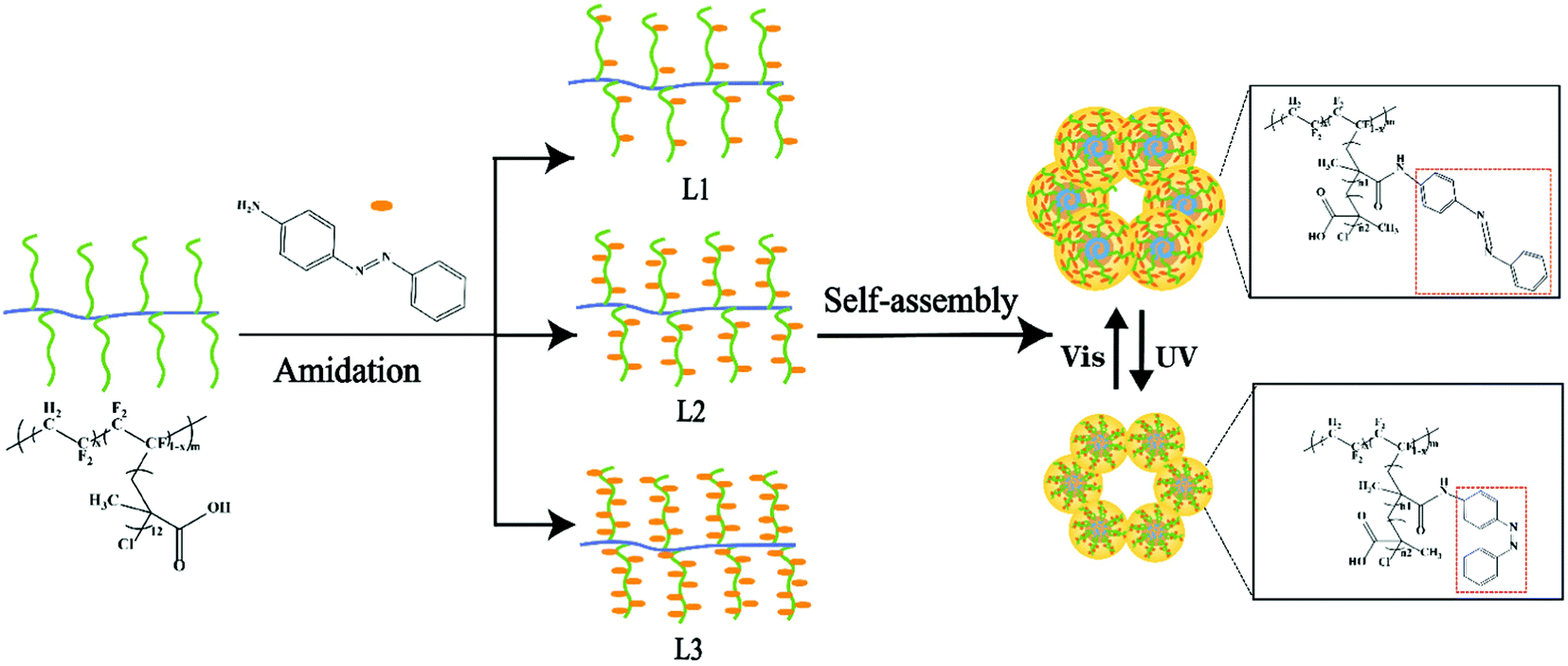
The azobenzene group composed of two phenyl rings linked by a N![[double bond, length as m-dash]](https://www.rsc.org/images/entities/char_e001.gif) N double bond can undergo photoisomerization of trans and cis isomers.16 In this study, the azobenzene groups were grafted onto the P(VDF-CTFE) backbone through amidation as shown in Fig. 1. Consequently, the photoswitchable conformation of azobenzene would contribute to the photo-responsive function of the synthesized polymer which would be subsequently adopted to prepare the PRMs.
N double bond can undergo photoisomerization of trans and cis isomers.16 In this study, the azobenzene groups were grafted onto the P(VDF-CTFE) backbone through amidation as shown in Fig. 1. Consequently, the photoswitchable conformation of azobenzene would contribute to the photo-responsive function of the synthesized polymer which would be subsequently adopted to prepare the PRMs.
 | ||
| Fig. 1 Schematic of the functional polymer preparation and the photo-responsive function. | ||
1H NMR spectra were adopted to characterize the synthesis of P(VDF-CTFE)-PMAA-Azo. After polymerization of tBMA onto the P(VDF-CTFE) backbone, two new peaks at 1.5 ppm and 1.8 ppm which could be assigned to the tert-butyl group and the methyl group of the grafted PtBMA, respectively,28 were observed in the 1H NMR spectrum of P(VDF-CTFE)-PtBMA (Fig. S1a, ESI†). In addition, based on the 1H NMR spectra, it could be estimated that about 12 tBMA repeat units were grafted onto the macro-initiator P(VDF-CTFE). After hydrolysis, the peak at 1.5 ppm almost disappeared from the 1H NMR spectrum of P(VDF-CTFE)-PMAA (Fig. S1b, ESI†). Subsequently, the carboxylic groups of P(VDF-CTFE)-PMAA reacted with the amine groups of Azo. As shown in Fig. 2, the 1H NMR spectrum of P(VDF-CTFE)-PMAA-Azo showed new peaks at 8.7 ppm, 8.5 ppm, 7.6 ppm and 7.5 ppm which could be assigned to the protons from the benzene rings.29 In addition, the number of carboxylic groups on the PMAA chain grafted with the azobenzene groups was estimated from the 1H NMR spectra of P(VDF-CTFE)-PMAA-Azo. Consequently, about 3, 5 and 9 out of 12 carboxylic groups of P(VDF-CTFE)-PMAA were grafted with the azobenzene groups, which were denoted as L1, L2 and L3, respectively.
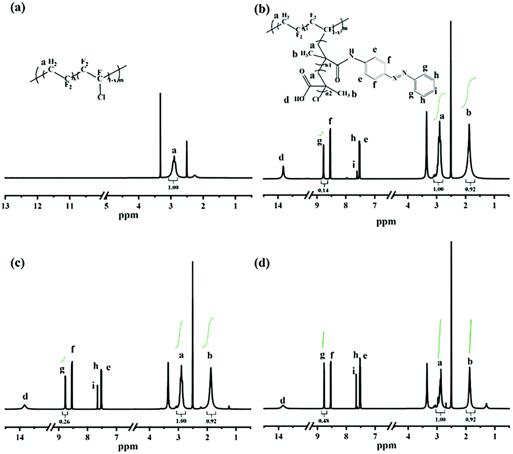 | ||
| Fig. 2 1H NMR spectra of (a) P(VDF-CTFE), (b) L1, (c) L2, and (d) L3. | ||
FTIR spectra were also used to verify the synthesis of P(VDF-CTFE)-PMAA-Azo. As shown in Fig. S2 (ESI†), the FTIR spectrum of P(VDF-CTFE)-PtBMA indicated a new peak at 1732 cm−1 which could be assigned to the ester carbonyl group of tBMA and subsequently substituted by a peak at 1708 cm−1 corresponding to the carboxylic groups of P(VDF-CTFE)-PMAA after hydrolysis.30 Moreover, the FTIR spectrum of P(VDF-CTFE)-PMAA-Azo in Fig. 3 showed three new peaks at 1595 cm−1, 1649 cm−1 and 3442 cm−1 which could be assigned to the benzene group, the amide carbonyl group and the stretching vibration of N–H bond from the amide group, respectively.30
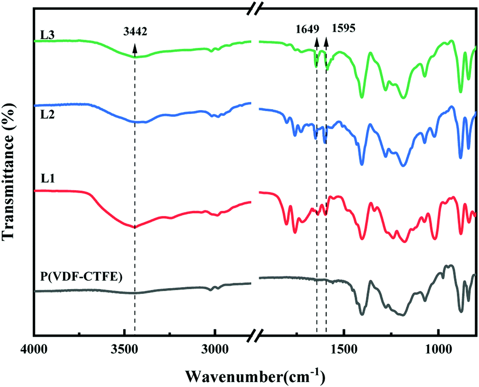 | ||
| Fig. 3 FTIR spectra of P(VDF-CTFE), L1, L2 and L3. | ||
In short, both the 1H NMR and the FTIR spectra verified the polymerization of tBMA from P(VDF-CTFE); subsequently, the hydrolysis process removed the tert-butyl groups to generate P(VDF-CTFE)-PMAA; eventually, the partial amidation between PMAA and Azo produced the P(VDF-CTFE)-PMAA-Azo polymers with different contents of azobenzene.
PRMs were prepared from the synthesized photo-responsive polymers: the L1, L2 and L3 polymers were adopted to produce M1, M2 and M3, respectively, through a non-solvent-induced phase-inversion protocol. The control membranes prepared from P(VDF-CTFE) with and without pores were denoted as MC and M0, respectively. The surface chemical compositions of the prepared membranes were characterized by XPS. As shown in Fig. 4, as compared with M0, the full spectra of PRMs showed two new peaks at 532.2 eV and 400.13 eV which could be assigned to the O 1s and N 1s orbitals, respectively. Obviously, the grafting of azobenzene should be responsible for the presence of oxygen and nitrogen elements on the PRMs. By the way, the existence of pore-forming agent introduced the oxygen content to the MC membrane. Moreover, based on the XPS spectra, the relative elemental distributions of the prepared membranes were determined, as shown in Table 3. The nitrogen molar percentages of M1, M2 and M3 were 4.03, 6.69 and 9.86%, respectively. Obviously, a higher nitrogen content indicated a higher grafting percentage of azobenzene, which was consistent with the 1H NMR data of P(VDF-CTFE)-PMAA-Azo. There is no doubt that the chemical composition of P(VDF-CTFE)-PMAA-Azo had been well preserved on the PRMs.
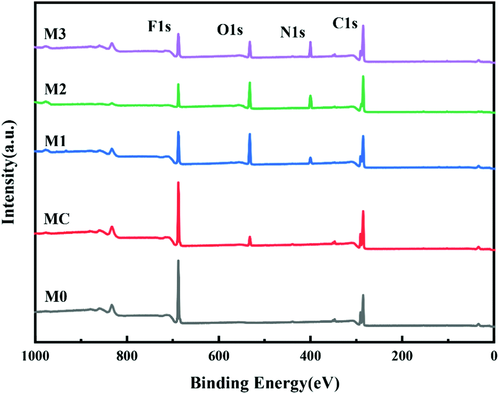 | ||
| Fig. 4 XPS wide scans of the prepared membranes. | ||
| Membrane | Surface elements (mol%) | |||
|---|---|---|---|---|
| C 1s | F 1s | O 1s | N 1s | |
| M0 | 57.14 | 42.86 | 0 | 0 |
| MC | 59.26 | 36.38 | 4.36 | 0 |
| M1 | 67.36 | 11.25 | 17.36 | 4.03 |
| M2 | 70.12 | 9.81 | 13.30 | 6.69 |
| M3 | 73.87 | 8.23 | 8.05 | 9.86 |
The surface and cross-sectional morphologies of the prepared membranes were observed by SEM. As shown in Fig. 5, M0 did not show any pores on the surface, while irregular large pores were shown by MC using PEG as the pore-forming agent; by contrast, relatively homogeneous pores were observed from the surfaces of PRMs, which could be the gaps among the aggregated micelles. It has been reported that polymers containing both hydrophilic and hydrophobic segments tend to form isoporous membranes.31 It is possible that the homogeneous pores would result in enhanced permeability of PRMs. On the other hand, dense separation layers supported with porous structures were observed from the cross-sectional images of PRMs, which would reduce the resistance of water penetration. Thicknesses of the prepared membranes were measured by ImageJ based on the cross-sectional images in Fig. 5. The thicknesses of M0, MC, M1, M2 and M3 were 67.6 ± 1.5, 67.5 ± 1.8, 71.1 ± 1.1, 71.6 ± 0.8 and 68.0 ± 1.3 μm, respectively. The membrane thickness was not obviously affected by the photo-responsive modification of P(VDF-CTFE), which was desired for the subsequent PRM performance evaluations.
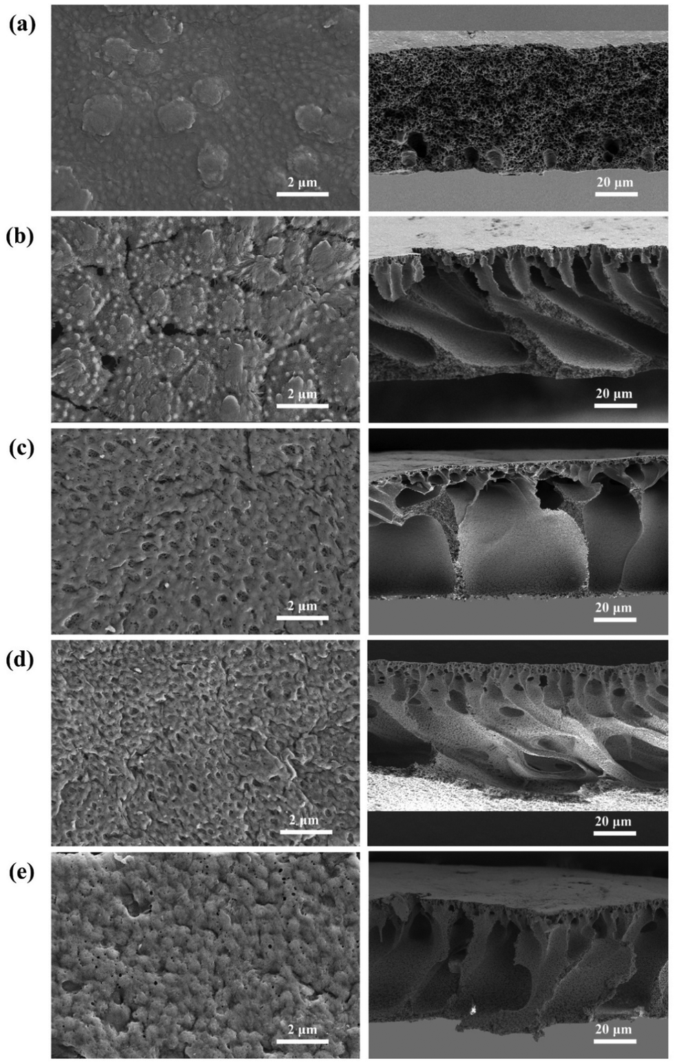 | ||
| Fig. 5 SEM images of the surfaces (left) and the cross-sections (right) of (a) M0, (b) MC, (c) M1, (d) M2 and (e) M3. | ||
3.2 Pore size and hydrophilicity switching of the photo-responsive membranes
Azobenzene groups were successfully grafted onto the PVDF-CTFE backbone, whose conformation switch could be triggered by changing the wavelength of the irradiation light.32 Consequently, the light-induced molecular motion of azobenzene would lead to the pore size variation of the PRMs.16 Especially, the pore size variation of PRMs triggered by light switching was inspired by plant leaf stomatal closure stimulated by temperature. Interestingly, the thicknesses of PRMs were similar to that of the control membrane (MC), which would minimize the possible influence caused by membrane thickness variation on the photo-responsive performance.The pore size variation range and distribution of PRMs after irradiation by visible and UV light were estimated by the probability density function model, when the retention rates of PEG and PEOs with different molecular weights by PRMs were measured.27 As shown in Fig. 6, Fig. S3 and Table S1 (ESI†), the average pore sizes of MC, M1, M2 and M3 after visible light irradiation were 27.6, 11.9, 9.0, and 6.6 nm, respectively, which were shifted to 26.9, 15.1, 12.8, and 12.3 nm, respectively, after UV irradiation. The prepared membranes were all in the UF range. As expected, the MC membrane did not exhibit any response to the light irradiation switch, while PRMs indicated obvious pore size changes. On the other hand, these results indicated that the azobenzene grafting process would narrow the membrane pores to some extent. It is possible that a higher content of hydrophobic azobenzene might suppress the phase-inversion process, resulting in smaller membrane pores.33 Moreover, the pore size expansion rates of M1, M2 and M3 were 27%, 42%, and 86%, respectively. Obviously, the pore size expansion rate of the PRMs was increasing with the azobenzene grafting rate. It seems that with more photo-responsive azobenzene groups grafted onto the polymer chain, the membrane pore size would be varied to a larger extent by light switching. It is possible that a higher content of azobenzene would cause more significant photoisomerization of the PMAA-Azo chain; consequently, more obvious micelle size and subsequent pore size variations were observed from the polymer with a higher content of azobenzene.
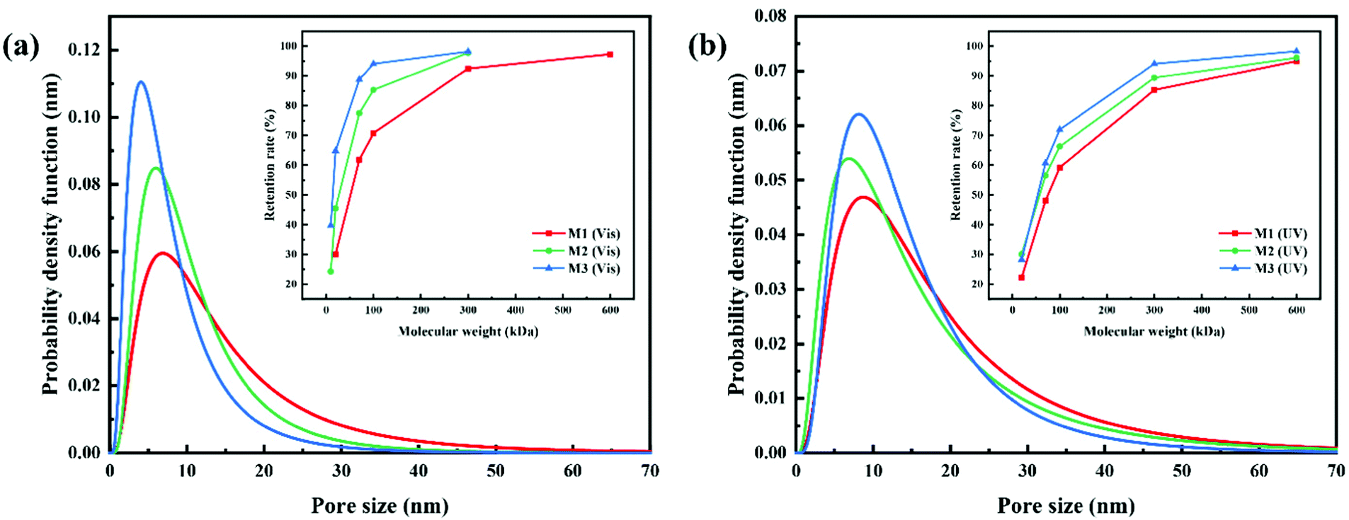 | ||
| Fig. 6 Pore size distribution of PRMs for (a) visible light and (b) UV light determined by retention of PEG/PEOs with different molecular weights. | ||
In addition, the standard deviation (SD) of the pore size distributions were 3.4, 2.1, 1.9, and 2.1 nm after visible light irradiation, and 3.2, 2.1, 2.2, and 1.9 nm after UV exposure, for MC, M1, M2, and M3, respectively. Obviously, the SD values of the PRMs were significantly lower than that of MC, indicating the narrower pore size distribution of PRMs than MC. Moreover, the pore size distributions of the PRMs were close to those of isoporous membranes reported in the literature.34 Thus, not only light-switchable pore size but also high permeability of PRMs would be expected in this study.
Pure water flux (PWF) of the prepared membranes after irradiation by visible and UV light was determined with a dead-end filtration system. As shown in Fig. 7a and Table S2 (ESI†), the PWFs of M1, M2 and M3 after visible light irradiation were 164.3 ± 3.3, 113.8 ± 2.4 and 64.7 ± 2.5 L m−2 h−1, respectively; when the irradiation was changed to UV light, the PWFs of M1, M2 and M3 were 206.4 ± 4.8, 172.3 ± 5.4 and 140.1 ± 3.0 L m−2 h−1, respectively. By contrast, the PWFs of MC under irradiation of visible and UV light were 105.0 ± 1.6 and 104.4 ± 3.1 L m−2 h−1, respectively, which were almost unchanged. Obviously, the PWFs of PRMs were all increased when the irradiation was switched from visible to UV light. In addition, the PWF of PRMs was decreasing with increasing azobenzene grafting percentage. It is possible that the higher grafting density would create narrower water channels or larger resistance of the membrane. More importantly, the PWFs of M1 were all much higher than the PWFs of MC regardless of the irradiation conditions, even though the pore size of M1 was much smaller than that of MC. This could be attributed to the much narrower pore size distribution of M1 than MC. As compared with UF membranes with similar pore sizes reported in the literature, the permeability of the PRMs was highly competitive.34
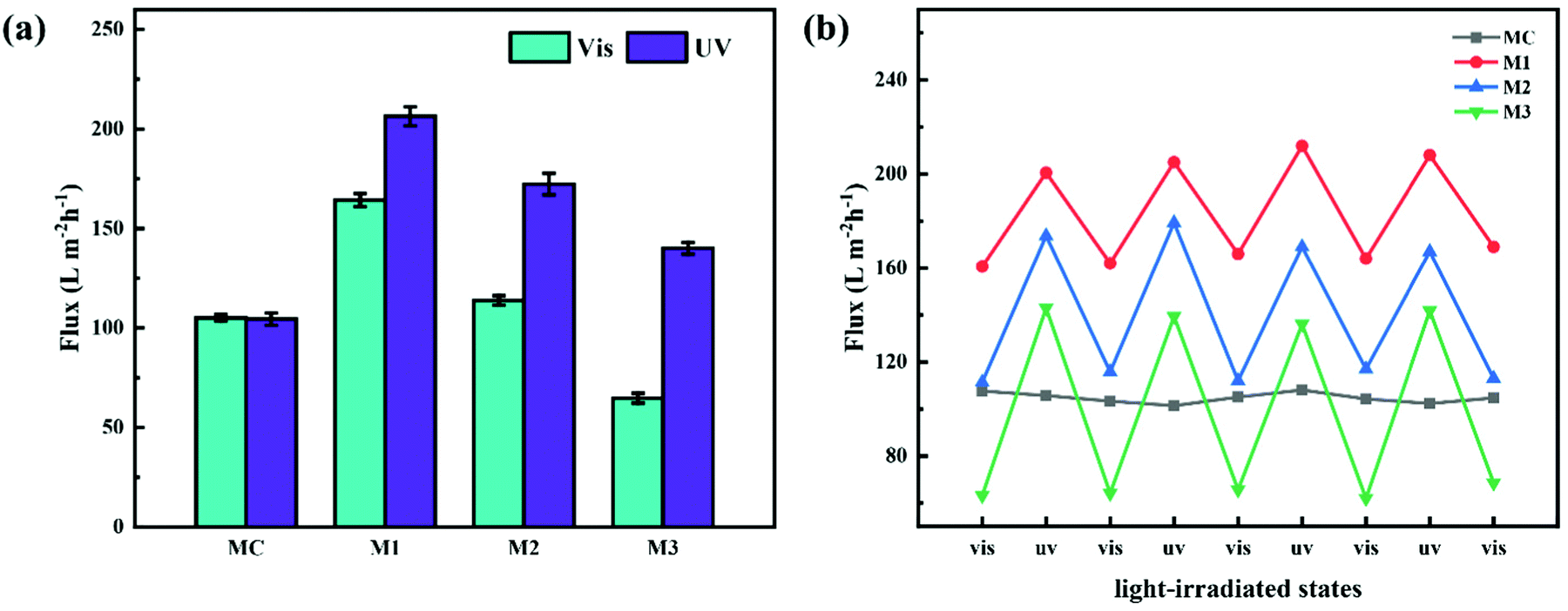 | ||
| Fig. 7 Photo-responsive performances of PRMs: (a) pure water flux of MC, M1, M2 and M3 for irradiation of visible and UV light; (b) pure water flux of MC, M1, M2 and M3 when the irradiation light was switched for four cycles. | ||
On the other hand, the ratios of PWF after visible light exposure to PWF after UV exposure were 1.3, 1.5 and 2.2 for M1, M2 and M3, respectively. The ratio of the flux increase after light switching from visible to UV was increasing with the grafting percentage of the azobenzene groups on the PMAA chain, which was consistent with the membrane pore size variation data of PRMs. This implied that the PWF increase could be attributed to the pore size increase after UV irradiation of PRMs.
Subsequently, the light switching cycle was repeated four times to evaluate the reversibility of the photo-triggered membrane pore size variation. As shown in Fig. 7b, the PWFs of the PRMs exposed to either visible or UV light were almost constant in the four cycles, which indicated that the photo-triggered pore size variations of the PRMs were reversible.
The P(VDF-CTFE)-PMAA-Azo polymer was composed of polymeric segments with varied hydrophilicities. Consequently, the heterogeneous polymer would form micelles which would subsequently aggregate into a membrane in the non-solvent, while gaps among the micelles would be the homogeneous pores of the formed membrane. It is possible that the high flux of the PRM could be contributed by the formed homogeneous pores. Moreover, to study the potential mechanism of PRM pore size variation, the hydrodynamic diameters of micelles assembled from the P(VDF-CTFE)-PMAA-Azo polymers were determined by DLS after different light irradiations for four cycles. As shown in Fig. 8 and Table S3 (ESI†), the hydrodynamic diameters of micelles assembled from L1, L2, and L3 were 358.4 ± 4.0, 404.6 ± 5.6, and 511.8.6 ± 4.2 nm, respectively, after visible light exposure, which were shifted to 294.5 ± 5.5, 333.75 ± 2.9, and 355.3 ± 3.9 nm, respectively, after UV irradiation. Obviously, the size of the P(VDF-CTFE)-PMAA-Azo micelles decreased when the irradiation was switched from visible light to UV; in addition, the micelle size switch was reversible in four cycles. Consequently, the gaps among the micelles were enlarged after UV exposure, resulting in the increased flux of the PRMs.
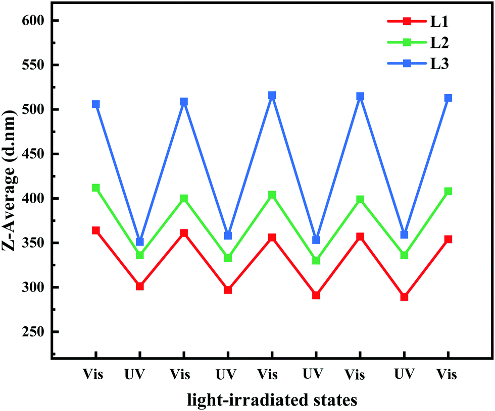 | ||
| Fig. 8 Z-Average sizes of micelles prepared by L1, L2, and L3 exposed to visible and UV light. | ||
Besides pore size, surface hydrophilicity of PRMs also could be varied by light irradiation switching. Water contact angle (CA) was determined by the static bubble captive method to evaluate surface hydrophilicity of the prepared membranes after different light irradiations. As shown in Fig. 9 and Table S4 (ESI†), during visible light exposure, the CAs of MC, M1, M2, and M3 were 42.6 ± 1.6, 27.2 ± 1.4, 31.7 ± 2.5, and 38.9 ± 2.3°, respectively, which were shifted to 42.3 ± 1.2, 24.6 ± 1.8, 26.5 ± 2.2, and 31.4 ± 2.1°, respectively, after UV irradiation. It is obvious that the hydrophilicity of MC was relatively low and did not respond to the light switching. By contrast, the introduction of the hydrophilic PMAA chain to P(VDF-CTFE) noticeably increased the hydrophilicity of the functional polymer and subsequently PRMs; however, the grafting of azobenzene gradually reduced the hydrophilicity of the PRMs, which would consume the hydrophilic carboxylic groups. Even the grafting of azobenzene slightly affected the hydrophilicity of PRMs; PRMs were still significantly more hydrophilic than the MC membrane.
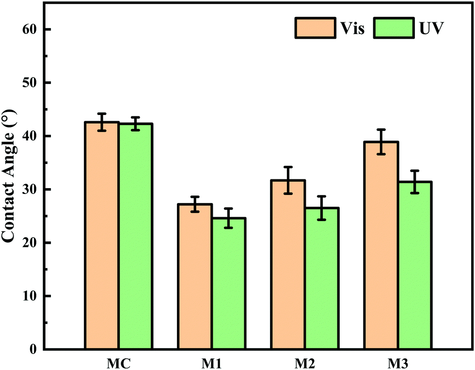 | ||
| Fig. 9 Water contact angles of MC, M1, M2 and M3 in visible and UV light. | ||
On the other hand, the hydrophilicity of PRMs was obviously enhanced when the illumination was switched from visible to UV light; in addition, the hydrophilicity variation extent of PRMs increased with the azobenzene grafting percentage. These phenomena should be contributed by the photoisomerization of azobenzene from the trans to the cis state resulting in a dipole moment change which changed the polarity of azobenzene35 and accordingly increased the hydrophilicity of the PRM surfaces. The more hydrophilic membrane surface after UV irradiation than after exposure to visible light would enhance to the membrane fouling mitigation, which would significantly contribute to the “light-cleaning” effect of PRMs.
3.3 “Light-cleaning” effect of the photo-responsive membrane
Membrane fouling is inevitable during membrane filtration, and physical cleaning such as backwashing is a routine for most membrane separations.36 However, organic and biological fouling is usually considered as irreversible membrane fouling, which cannot be effectively removed by conventional physical and chemical cleaning protocols.37 It is extremely important to mitigate the influence caused by irreversible membrane fouling. In this study, PRMs responded to light irradiation switching in terms of pore size and surface hydrophilicity, which could potentially enhance the cleaning effect of conventional backflushing. A typical organic foulant, BSA, and a typical biological foulant, E. coli,38 were adopted to evaluate the “light-cleaning” effect of the PRMs. As shown in Fig. 10a and c, the flux decline of MC was the most significant after filtration of both BSA and E. coli, which mostly could not be recovered by backflushing; by contrast, M1 exhibited the lowest flux decline and the highest flux recovery rate after backflushing under visible light during filtration of both BSA and E. coli; in addition, the flux decline percentage was slightly increased, while the flux recovery of PRM after backflushing was slightly decreased with increasing content of azobenzene or hydrophobicity. Obviously, the enhanced hydrophilicity would contribute to the resistance of irreversible membrane fouling.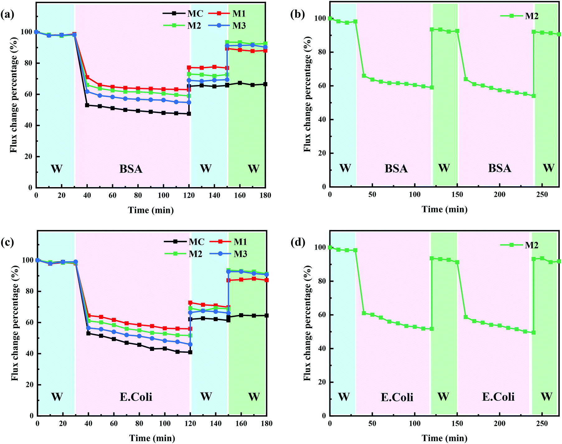 | ||
| Fig. 10 Flux change percentage of the prepared membranes during the filtration of (a and b) BSA solution and (c and d) E. coli suspension, DI water after backflushing and after backflushing under UV irradiation. | ||
Moreover, backflushing was conducted again under the irradiation of UV light; subsequently, the relatively flux recovery after “light-cleaning” was denoted as RFRL. As shown in Fig. 10a, c and Tables S5, S6 (ESI†), the RFRL of MC was close to RFR; by contrast, the RFRL of PRM was significantly higher than RFR. The obvious flux recovery of PRM after backflushing under UV exposure could be attributed to pore size and surface hydrophilicity enhancement triggered by the light switch. In addition, the more significant pore size and hydrophilicity improvement after light switching would result in slightly better “light-cleaning” effect of PRMs. On the other hand, the BSA retention rates were 42, 74, 79, and 81% for MC, M1, M2, and M3, respectively. The molecular size of BSA is about 4.0 nm39 which is too small to be completely retained by the prepared membranes, although about 80% retention of BSA by either M2 or M3 was acceptable for most scenarios. By contrast, the prepared membranes falling into the UF range could well retain E. coli in the micrometric range.
To evaluate the reusability of PRMs, two filtration and “light-cleaning” cycles were conducted for M2 to filter BSA and E. coli. As shown in Fig. 10b, d and Table S7 (ESI†), the RFRL of M2 after the second filtration cycle was close to that after the first cycle during the filtration of both BSA and E. coli. These results indicated that the “light-cleaning” performance of the PRM was stable for multicycle filtrations.
3.4 Light-triggered molecule release by the photo-responsive membrane
The pore size of PRM could be switched by the irradiation light change, which provided a promising solution to control the release of certain molecules triggered by light switching. In this study, two model molecules, PVP (Mw: 30 kDa) and PEO3 (Mw: 100 kDa), were mixed and subsequently released by M3 in sequence. As shown in Fig. 11, under the irradiation of visible light, the PVP molecules could freely penetrate M3 while the PEO3 molecules were completely retained; after five filtration and refill cycles, the PVP molecules were completely released from the mixture; subsequently, the irradiation light was switched to UV, which triggered the complete release of PEO3 in the following five filtration and refill cycles. The mass balance calculation (Table S8, ESI†) confirmed the complete recovery of both PVP and PEO3 in the controlled release process. Obviously, the PRM was able to control the release of molecules with a size larger than the pores under visible light exposure but smaller than the pores under UV irradiation. Moreover, the pore size variation range of the PRM could be adjusted by the grafting percentage of azobenzene, which enabled the controlled release of molecules with different sizes following the above rule.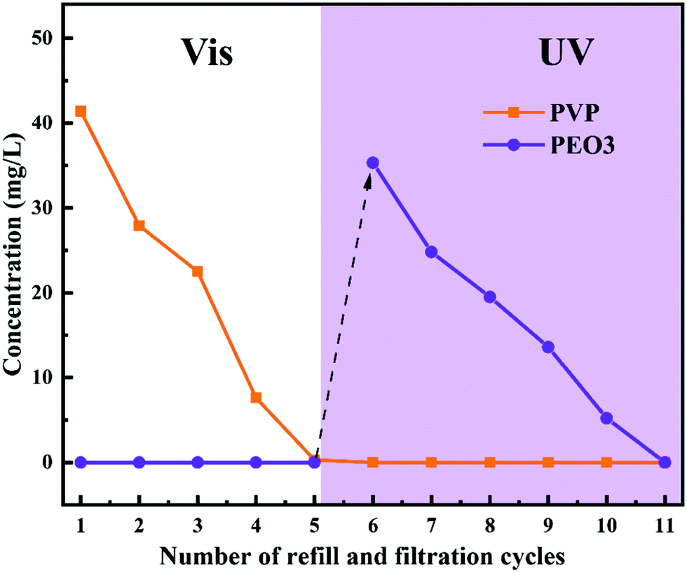 | ||
| Fig. 11 Concentrations of PVP and PEO3 penetrating M3 after different filtration and refill cycles under visible and UV light exposure. | ||
4. Conclusion
In this study, a PMAA chain containing 12 repeat units was grafted from the macroinitiator P(VDF-CTFE). Subsequently, about 3, 5 and 9 out of the 12 carboxylic groups from PMAA were reacted with the amine group of Azo, resulting in photo-responsive polymers (L1, L2 and L3) with different contents of azobenzene. PRMs were prepared from the L1, L2 and L3 polymers following a non-solvent-induced phase-inversion protocol. PRMs showed higher PWF than the conventional UF membrane with similar retention capability because of the narrow pore size distribution. More importantly, the pore size of PRMs could be enlarged when the irradiation was switched from visible to UV light and vice versa. In addition, the higher the content of azobenzene the more obvious the pore size variation after light switching but the smaller the absolute pore size observed for PRMs. Moreover, the surface hydrophilicity of PRMs could be increased when visible light irradiation was switched to UV light and vice versa. The photo-responsive pore size and hydrophilicity of PRMs enabled the “light-cleaning” effect that backflushing under UV irradiation of PRM would recover most of the irreversible flux decline caused by a typical organic foulant (BSA) and a biological foulant (E. coli). On the other hand, the light-switching gates of PRM enabled the controlled release of molecules with different sizes.Conflicts of interest
There are no conflicts to declare.Acknowledgements
This project was supported by the National Key Research and Development Program of China (2017YFA0207001, 2018YFC1800705) and the ZJU Tang Scholar.References
- J. R. Werber, C. O. Osuji and M. Elimelech, Nat. Rev. Mater., 2016, 1, 16 CrossRef.
- F. X. Kong, Q. Liu, L. Q. Dong, T. Zhang, Y. B. Wei, J. F. Chen, Y. Wang and C. M. Guo, J. Membr. Sci., 2020, 612, 118338 CrossRef CAS.
- X. F. Dong and Q. C. Ge, ACS Appl. Mater. Interfaces, 2019, 11, 37163–37171 CrossRef CAS PubMed.
- M. J. Zhao, W. H. Wu and B. Su, ACS Appl. Mater. Interfaces, 2018, 10, 33986–33992 CrossRef CAS PubMed.
- K. R. Zodrow, M. E. Tousley and M. Elimelech, J. Membr. Sci., 2014, 453, 84–91 CrossRef CAS.
- H. B. Park, J. Kamcev, L. M. Robeson, M. Elimelech and B. D. Freeman, Science, 2017, 356, eaab0530 CrossRef PubMed.
- A. Deshmukh, C. Boo, V. Karanikola, S. H. Lin, A. P. Straub, T. Z. Tong, D. M. Warsinger and M. Elimelech, Energy Environ. Sci., 2018, 11, 1177–1196 RSC.
- D. J. Miller, D. R. Dreyer, C. W. Bielawski, D. R. Paul and B. D. Freeman, Angew. Chem., Int. Ed., 2017, 56, 4662–4711 CrossRef CAS PubMed.
- S. F. Zhao, Z. P. Liao, A. Fane, J. S. Li, C. Y. Tang, C. M. Zheng, J. Y. Lin and L. X. Kong, Desalination, 2021, 499, 114857 CrossRef CAS.
- G. Goel, C. Hélix-Nielsen, H. M. Upadhyaya and S. Goel, npj Clean Water, 2021, 4, 41 CrossRef CAS.
- C. S. Lee, M. K. Choi, Y. Y. Hwang, H. Kim, M. K. Kim and Y. J. Lee, Adv. Mater., 2018, 30, 1705944 CrossRef PubMed.
- I. Kocsis, Z. Sun, Y. M. Legrand and M. Barboiu, npj Clean Water, 2018, 1, 13 CrossRef.
- W. Song, H. Joshi, R. Chowdhury, J. S. Najem, Y.-X. Shen, C. Lang, C. B. Henderson, Y.-M. Tu, M. Farell, M. E. Pitz, C. D. Maranas, P. S. Cremer, R. J. Hickey, S. A. Sarles, J.-l. Hou, A. Aksimentiev and M. Kumar, Nat. Nanotechnol., 2020, 15, 73–79 CrossRef CAS PubMed.
- W. J. Ma, S. K. Samal, Z. C. Liu, R. H. Xiong, S. C. De Smedt, B. Bhushan, Q. L. Zhang and C. B. Huang, J. Membr. Sci., 2017, 537, 128–139 CrossRef CAS.
- R. Cao, M. Qin, C. Liu, S. Li, P. Guo, G. Han, X. Hu, W. Feng and L. Chen, ACS Appl. Mater. Interfaces, 2020, 12, 14352–14364 CrossRef CAS PubMed.
- M. K. Purkait, M. K. Sinha, P. Mondal and R. Singh, in Interface Science and Technology, ed. M. K. Purkait, M. K. Sinha, P. Mondal and R. Singh, Elsevier, 2018, vol. 25, pp. 115–144 Search PubMed.
- A. Nayak, H. Liu and G. Belfort, Angew. Chem., Int. Ed., 2006, 45, 4094–4098 CrossRef CAS PubMed.
- W. Shi, J. Deng, H. Qin, D. Wang and C. Zhao, J. Membr. Sci., 2014, 455, 357–367 CrossRef CAS.
- K. Xiao, J. Y. Sun, Y. H. Mo, Z. Fang, P. Liang, X. Huang, J. B. Ma and B. R. Ma, Desalination, 2014, 343, 217–225 CrossRef CAS.
- W. X. Zhang, L. H. Ding, J. Q. Luo, M. Y. Jaffrin and B. Tang, Chem. Eng. J., 2016, 302, 446–458 CrossRef CAS.
- X. Zheng, Z. Y. Guo, D. L. Tian, X. F. Zhang, W. X. Li and L. Jiang, ACS Appl. Mater. Interfaces, 2015, 7, 4336–4343 CrossRef CAS PubMed.
- J. A. Maurer, M. J. Miller and S. F. Bartolucci, J. Colloid Interface Sci., 2018, 524, 204–208 CrossRef CAS PubMed.
- Y. Lu, S. Sathasivam, J. L. Song, C. R. Crick, C. J. Carmalt and I. P. Parkin, Science, 2015, 347, 1132–1135 CrossRef CAS PubMed.
- A. Biswas and N. R. Jana, ACS Appl. Nano Mater., 2021, 4, 877–885 CrossRef CAS.
- X. Jiang, Y. Shao, J. Li, M. Wu, Y. Niu, X. Ruan, X. Yan, X. Li and G. He, ACS Nano, 2020, 14, 17376–17386 CrossRef CAS PubMed.
- Y. Hu, M. Yue, F. Yuan, L. Yang, C. Chen and D. Sun, J. Membr. Sci., 2021, 621, 118982 CrossRef CAS.
- S. Singh, K. C. Khulbe, T. Matsuura and P. Ramamurthy, J. Membr. Sci., 1998, 142, 111–127 CrossRef CAS.
- J. F. Hester, P. Banerjee, Y. Y. Won, A. Akthakul, M. H. Acar and A. M. Mayes, Macromolecules, 2002, 35, 7652–7661 CrossRef CAS.
- I. C. Y. Hou, V. Diez-Cabanes, A. Galanti, M. Valasek, M. Mayor, J. Cornil, A. Narita, P. Samori and K. Mullen, Chem. Mater., 2019, 31, 6979–6985 CrossRef CAS.
- M. Badertscher, P. Bühlmann and E. Pretsch, Structure determination of organic compounds, Springer Berlin Heidelberg, 2009 Search PubMed.
- W. N. Zhang, P. P. Cheng, J. Cheng, N. Li, Y. Wang, J. Y. Yang, X. Y. Qiu, H. Tan and H. Z. Yu, J. Membr. Sci., 2019, 570, 427–435 CrossRef.
- S. K. Surampudi, H. R. Patel, G. Nagarjuna and D. Venkataraman, Chem. Commun., 2013, 49, 7519–7521 RSC.
- W. Zhao, Y. Su, C. Li, Q. Shi, X. Ning and Z. Jiang, J. Membr. Sci., 2008, 318, 405–412 CrossRef CAS.
- A. Tiraferri, N. Y. Yip, W. A. Phillip, J. D. Schiffman and M. Elimelech, J. Membr. Sci., 2011, 367, 340–352 CrossRef CAS.
- J. Groten, C. Bunte and J. Rühe, Langmuir, 2012, 28, 15038–15046 CrossRef CAS PubMed.
- Y. Gao, J. Qin, Z. Wang and S. W. Østerhus, J. Membr. Sci., 2019, 587, 117136 CrossRef CAS.
- K. Kimura, Y. Hane, Y. Watanabe, G. Amy and N. Ohkuma, Water Res., 2004, 38, 3431–3441 CrossRef CAS PubMed.
- K. P. Wai, C. H. Koo, Y. L. Pang, W. C. Chong and W. J. Lau, J. Water Process Eng., 2020, 33, 100989 CrossRef.
- N. Hampu, J. R. Werber, W. Y. Chan, E. C. Feinberg and M. A. Hillmyer, ACS Nano, 2020, 14, 16446–16471 CrossRef CAS PubMed.
Footnote |
| † Electronic supplementary information (ESI) available. See DOI: 10.1039/d1tb02329b |
| This journal is © The Royal Society of Chemistry 2022 |