Emerging ruthenium single-atom catalysts for the electrocatalytic hydrogen evolution reaction

Jingting Zhu a, Lejuan Cai b, Yudi Tu a, Lifu Zhang *a and Wenjing Zhang *a
aInternational Collaborative Laboratory of 2D Materials for Optoelectronics Science and Technology of Ministry of Education, Institute of Microscale Optoelectronics, Shenzhen University, Shenzhen 518060, China. E-mail: wjzhang@szu.edu.cn; zhanglifu@szu.edu.cn
bSongshan Lake Materials Laboratory, Dongguan 523808, Guangdong, China

Received 13th May 2022 , Accepted 27th June 2022

First published on 14th July 2022


Abstract

The electrocatalytic hydrogen evolution reaction (HER) is an efficient approach for producing hydrogen, which is a sustainable and eco-friendly energy carrier. Ruthenium-based HER catalysts are considered good alternatives to commercial platinum-based ones, because they have similar hydrogen bonding energy, lower water decomposition barrier and considerably lower price. Recently, emerging Ru single-atom catalysts (SACs) have shown greater advantage for HER than Ru nanoparticles, owing to their high atomic utilization efficiency, catalytic activity and selectivity. This review provides a comprehensive summary of the recent development of Ru SACs for HER applications. An overview of synthesis strategies, atomically resolved characterization methods and electrocatalytic studies with different support materials is provided. Finally, the unresolved challenges in the development of Ru SACs for industrial HER applications are discussed, and future research priorities are proposed. This review is expected to guide the rational design, appropriate fabrication, and performance optimization of advanced Ru SACs toward HER applications.

Introduction

As an efficient and clean energy carrier, H2 provides a high heat of combustion without pollutant emissions, and can be used in fuel cells to convert chemical energy to electrical energy. Additionally, H2 can be produced from water, which is an abundant resource on Earth. Therefore, it is considered the ideal energy carrier among all kinds of renewable energy sources.1,2 Current industrial techniques produce H2 from fossil fuels, which consume a large amount of non-renewable energy and inevitably bring about CO2 emission.3,4 For large-scale H2 production, the hydrogen evolution reaction (HER) based on water electrolysis has attracted considerable attention, which is an economically viable and highly efficient approach with low environmental impact due to its sustainable and non-polluting nature.5 However, the electrocatalytic HER generally requires a high overpotential (applied voltage), leading to high electrical energy consumption.3 Therefore, an efficient and stable catalyst is urgently required to reduce the overpotential and the corresponding energy consumption.

Currently, Pt is considered the most efficient catalyst for HER, although its scarcity and high cost limit its use in the industrial-scale production of H2.6 Ru is considered a less expensive alternative to Pt, because it is available at one half of the cost of Pt (e.g., $18.5 g−1, March 2022 price7) and has a similar bond strength with H2 (∼272 kJ mol−1).8 According to experimental results and density functional theory (DFT) calculations, the HER activity of Ru is similar to that of Pt. In addition, Ru is sufficiently stable in electrolytes with a wide range of pH.9 Therefore, Ru-based HER catalysts have been widely investigated, and review articles that focus on their synthesis processes10–12 or performance optimization2,13 have been extensively published. With increasing attention given to single-atom catalysts (SACs), Ru SACs with isolated Ru single atoms (SAs) dispersed on specific supports have emerged as a new research frontier in materials science and catalysis.14,15 Compared with clusters and nanoparticles (NPs), Ru SAs have inherent advantages in terms of their maximum atomic utilization efficiency, higher mass activity and unique quantum-size effect. More importantly, the strong interaction between Ru SAs and their support can effectively modify the electronic structure of active Ru catalytic sites and redistribute the localized charges, which may facilitate the Volmer step and H–H coupling process, contributing to high catalytic activity, selectivity and stability.16,17 In recent years, an increasing number of Ru SACs with excellent HER catalytic activity have been reported. However, to date, there is still no review focusing on Ru SACs for HER applications.

The aim of this review is to overview the recent progress in the development of Ru SACs for HER. First, various synthesis strategies for Ru SACs are summarized. Then, the characterization techniques for probing and identifying the active Ru sites at the atomic level are presented. Subsequently, a detailed review of the HER performance of Ru SACs with different supports is provided. In addition, the discussion covers the mechanisms how the unique electronic and structural characteristics of Ru SACs enhance their electrocatalytic HER performance. Finally, the existing challenges are discussed and some prospects for future development of Ru SACs for HER applications are proposed.

Synthesis of Ru single-atom catalysts

Controllable fabrication of stable metal SACs is a big challenge. Due to the high surface free energy of isolated metal atoms, SAC synthesis usually requires strictly controlled conditions to prevent metal-atom aggregation and cluster/nanocrystal growth.18 In recent years, various approaches to Ru SAC synthesis have been developed, including wetness impregnation (WI), electrodeposition, photochemical reduction (PR) and high-temperature pyrolysis. Based on emerging advances, several strategies for preparing Ru SACs are summarized here.

Wetness impregnation

WI is a common method for Ru SAC synthesis. In a typical WI process, the Ru precursor is uniformly mixed into a suspension of the support material, and the mixture is dried and calcined to remove volatile components, resulting in the deposition of Ru on the support surface. When the Ru loading content is reduced sufficiently, SAs are obtained on the support. However, it is difficult to achieve homogeneous SA distribution on the support surface. Therefore, the synthesis parameters, including the support material's type, the type and concentration of Ru precursor and the solution pH, should be optimized to ensure uniform Ru SA distribution.19

For instance, Cao et al. prepared Ru SAs anchored on a C3N4 support (RuSA–C3N4) via a WI method, in which RuCl3 aqueous solution was mixed with P-decorated C3N4, and the mixture was then calcined in an Ar atmosphere.20 The as-prepared RuSA–C3N4 catalyst had a two-dimensional nanosheet (NS) structure without apparent particles or clusters of Ru species. This study confirmed that C3N4 with abundant unsaturated N (rich with lone pair electrons) contains ideal anchoring sites for immobilizing metal ions to achieve atomic-scale dispersion. Li et al. developed a thermo-driven WI method to insert Ru SAs into GaS NSs.21 In this study, pristine GaS NSs were dispersed in deionized water via ultrasonication followed by dropwise adding RuCl3 solution. Ru SAC was obtained by subsequent treatment in an oil bath (80 °C for 24 h), followed by vacuum drying. It was noteworthy that the strong geometric confinement of GaS interlayers was found to inhibit atom aggregation, resulting in the effective formation of Ru SAs on GaS NS supports. Recently, Ru-based multi-site atomically dispersed catalyst (ADC) supported on S-doped carbon black (S–CB) was fabricated by a universal WI method.22 The highly active Ru ADC was obtained by mixing RuCl3·xH2O and S–CB in an aqueous solution followed by vacuum drying at room temperature. Moreover, Ru SAC was synthesized by washing Ru ADC with an acidic solution at 50 °C (Fig. 1a). This room-temperature WI method can also be extended to fabricate Pt, Rh, Ir, Au and Mo ADCs, which promotes the multiple applications of ADCs.


image file: d2ta03860a-f1.tif
Fig. 1 (a) WI synthesis route of Ru ADC and Ru SAC. (1) S doping in carbon black, (2) room-temperature WI for Ru ADC and (3) acid washing step for Ru SAC. Reprinted with permission from ref. 22. Copyright 2021 John Wiley and Sons. (b) The electrodeposition fabrication process of Ru–MoS2/CC catalyst. Reprinted with permission from ref. 23. Copyright 2019 Elsevier. (c) Schematic illustration for high-temperature pyrolysis preparation of RuNP/SA@N–TC and RuSA@N–TC samples. Reprinted with permission from ref. 32. Copyright 2020 John Wiley and Sons.

Electrodeposition

Electrodeposition is a simple and effective approach for the uniform deposition of Ru SAs on a selected conductive matrix, such as carbon cloth (CC), Ni foam and their composites with other materials. In the synthesis via an electrolytic reaction, the conductive matrix and a graphite material are used as the working electrode and counter electrode, respectively, and a solution containing Ru precursor is used as the electrolyte. The reaction time should be controlled precisely to prevent the growth of Ru NPs. Noted that, the Ru SAC based on conductive matrix can be directly used as H2 evolution cathode in the electrocatalytic HER process, which greatly simplifies the electrode preparation process. Additionally, this 3D self-supported Ru SAs electrode is favorable for charge transfer and H2 release, which may contribute to better HER performance.

For instance, Wang et al. electrodeposited Ru SAs on the surfaces of MoS2 NS arrays supported by CC (Ru–MoS2/CC) (Fig. 1b).23 The electrodeposition was performed in a three-electrode cell using MoS2/CC as the working electrode, a graphite plate as the counter electrode, a saturated calomel electrode (SCE) as the reference electrode, and a mixed solution of RuCl3 and H2SO4 as the electrolyte. Ru–MoS2/CC was obtained by cyclic voltammetry (CV) from −0.5 to 0.4 V (vs. SCE) at a sweep rate of 20 mV s−1 for 20 cycles. Li et al. reported an electrodeposition strategy to anchor Ru SAs on the surfaces of MoS2/MoP heterostructures supported by CC (CC@MoS2/MoP/RuSA).24 The electrodeposition was conducted in a two-electrode system using CC@MoS2/MoP as the working electrode, a graphite rod as the counter electrode, and a mixed solution of RuCl3 and NH2SO3H as the electrolyte. Ru SAs were electrodeposited on CC@MoS2/MoP under cathodic current of 0.2 mA cm−2 for 450 s.

Photochemical reduction

Over the past decades, PR has been considered one of the most effective strategies for preparing metal NPs, which has the advantages of simplicity and scalability.25 In this process, the size of final product mainly depends on the rate of nucleation and growth of the metal. To prepare Ru SACs by PR, it is crucial to prevent the agglomeration of Ru atoms by the strict control of precursor concentration and irradiation conditions.

For example, Yu et al. synthesized highly robust Ru SACs by mild ultraviolet PR.26 They mixed B-doped mesoporous carbon spheres with RuCl3 and urea, then stirred the mixture under UV irradiation for 120 min. Owing to the adjacent B,N co-doped pairs, Ru atoms were firmly anchored on B,N co-doped carbon (N/BC) by Ru–N–B–C sites, leading to enhanced metal–support interaction. Recently, Yu et al. fabricated Ru SAs supported on N-doped Mo2C NSs by PR combined with calcination.27 They firstly prepared Ru NPs/MoO2 NSs by stirring the mixture of MoO2 NSs and RuCl3·3H2O under the irradiation of a 300 W xenon lamp, and then Ru SAs/N–Mo2C NSs were obtained by calcining the as-prepared products mixed with commercial dicyandiamide powders via anti-Ostwald ripening.

High-temperature pyrolysis

High-temperature pyrolysis is considered as a facile and robust method for synthesizing Ru SACs. This strategy involves thermal decomposition of suitable Ru precursors at high temperature in a controlled inert atmosphere, such as N2,28,29 Ar,30 or NH3.31 The advantage of pyrolysis is the easy control of Ru loading, but the process uses a large amount of energy, requires strictly controlled reaction conditions and has a high cost. These disadvantages limit its suitability for large-scale application.

For example, Lu et al. demonstrated a pyrolysis strategy to fabricate an atomically dispersed Ru catalyst on N-doped carbon nanowires (Ru/NC NWs).28 A melamine formaldehyde polymer was coated onto Te NWs, and the core-sheath NWs were pyrolyzed at a controlled temperature after adding a calculated amount of RuCl3. This resulted in Ru,N co-doped carbon NWs where both Ru NPs and Ru SAs were embedded in the carbon matrix. Yan et al. introduced RuCl3 into NH2–MIL-125, where MIL (Materials of Institute Lavoisier)-125 is a metal organic framework, and prepared Ru NP and/or SA@N-doped TiO2/C hybrid catalysts (Ru@N–TC) via a pyrolysis process (Fig. 1c).32 The dispersion states of Ru species were directly regulated by varying the initial feeding content of Ru3+ ions, where RuNP/SA@N–TC and RuSA@N–TC were derived from 2% Ru3+–NH2–MIL-125 and 5% Ru3+–NH2–MIL-125, respectively.

Other strategies

In addition to the strategies for synthesizing Ru SACs discussed in above sections, several other effective approaches have been reported in recent years. For instance, an ion-exchange method was applied to stabilize Ru SAs on Ni–BDC (Ni2(OH)2(C8H4O4)) grown on Ni foam33 (Fig. 2a). By varying the concentration of RuCl3 ethanol solution, a series of Ru SACs were synthesized through a solvothermal process, with different loading amounts of Ru atoms partially replacing Ni atoms. Similarly, ion exchange for preparing Ru SACs has been achieved by hydrothermal treatment.34,35 He et al. reported an impregnation-phosphorization treatment to synthesize a Ni5P4 electrocatalyst incorporating Ru SAs (Ni5P4–RuSA) (Fig. 2b). As a support precursor, Ni-vacancy-rich Ni(OH)2 firstly stabilized the Ru3+ species from RuCl3, and then the Ni5P4–RuSA NPs were obtained through subsequent phosphorization treatment.36 Similarly, RuSA-doped Ni2P NPs (Ru SAs–Ni2P) were prepared by degassing a mixture of Ni(acac)2 and Ru (acac)2, followed by the subsequent phosphorization (Fig. 2c).37 Moreover, a simple spontaneous reduction method was developed recently to fabricate Ru SACs, where Ru SACs were deposited on monolayer MoS2 with a nanoporous structure (np-MoS2).38 In this method, an np-MoS2 film was transferred to the RuCl3·H2O solution to adsorb Ru species, then transferred to CC, and dried under vacuum to obtain RuSA/np-MoS2.
image file: d2ta03860a-f2.tif
Fig. 2 (a) Schematic illustration for ion-exchange preparation of NiRu0.13–BDC catalyst. Reprinted with permission from ref. 33. Copyright 2021 Nature Publishing Group. (b) Schematic illustration for impregnation-phosphorization synthesis of Ni5P4–RuSA. Reprinted with permission from ref. 36. Copyright 2020 John Wiley and Sons. (c) Schematic illustration of phosphorization preparation process of Ru SAs–Ni2P. Reprinted with permission from ref. 37. Copyright 2020 Elsevier.

Summary

In summary, Ru SACs can be obtained by various synthesis strategies, considering key factors such as time, cost, procedural complexity and yield. Generally, the synthesis approaches are classified into “bottom-up” and “top-down” routes.39,40 One of the most promising bottom-up strategies for preparing Ru SACs is WI due to its low cost and simple procedure. The Ru SAC products prepared by electrodeposition and PR generally have excellent catalytic activity. However, increasing the Ru loading is difficult using these three methods, because local agglomeration occurs easily due to their high nucleation rate.40,41 Previous studies have shown that the top-down strategies for preparing Ru SACs have higher synthesis efficiency than bottom-up ones. High-temperature pyrolysis is a commonly used top-down strategy. Ru SACs obtained by pyrolysis usually have excellent conductivity and catalytic performance. However, the main limitation of this strategy is the tendency of Ru atoms to aggregate at high temperatures. Therefore, a high level of optimization is generally required to achieve the desired isolated Ru SACs.42 Although some good progress has been made in preparing Ru SACs, the current preparation methods still have limitations, such as low and hard-to-control Ru SA loading and relatively low stability and repeatability. The small particle size of Ru SAs considerably increases their surface free energy, resulting in their agglomeration at high Ru loading. Thus, further research is required to fabricate Ru SACs with high Ru SA loading, high catalytic activity, sufficient stability, and a low cost of production.

Characterization of Ru single-atom catalysts

In recent years, the rapid development of electron microscopic technology and spectral characterization methods has supported an in-depth understanding of the spatial configuration and coordination of SAC active centers. The atomic-scale morphological characterization and in situ/operando spectroscopy methods with structural sensitivity have gradually clarified the structure–activity relationship of SACs. Representative methods for effectively verifying the distribution of isolated SAs include aberration-corrected scanning transmission electron microscopy (AC-STEM) with electron energy loss spectroscopy (EELS), X-ray absorption spectroscopy (XAS) and X-ray photoelectron spectroscopy (XPS).16,43,44 Specific examples of these methods for characterizing Ru SACs are described in detail in this section.

Aberration-corrected scanning transmission electron microscopy

Electron microscopy can be used to observe the morphology and structural characteristics at the microscale and plays a vital role in direct imaging of nanomaterials. However, the resolution of conventional electron microscopes is limited to the nanoscale, which remains a great challenge for the imaging and characterization at the atomic scale. With the development of aberration-correction technology, AC-STEM can enable atomic-scale imaging owing to the higher beam current and resulting higher resolution.45 Particularly, aberration-corrected high-angle annular dark-field scanning transmission electron microscopy (AC HAADF-STEM) can provide atomic-resolution images by collecting the electrons scattered from an annulus around the beam using an annular dark-field detector. This method can provide a distribution of different atoms within the material because the brightness increases with increasing atomic number. Therefore, the high-resolution imaging of AC-STEM makes it possible to visualize the sample at the atomic level, which lays a firm foundation for understanding the structure and composition of catalysts at the atomic level.46,47 For instance, isolated Ru atoms uniformly distributed on MoS2,38 C3N4,20 MXene (N-doped Ti3C2Tx)48 and TiO215 supports were clearly observed as bright dots in AC HAADF-STEM images (Fig. 3a–d). No Ru NPs or clusters were observed in any of these samples, further confirming the successful synthesis of Ru SACs.
image file: d2ta03860a-f3.tif
Fig. 3 (a) HAADF-STEM image of RuSA/np-MoS2, showing the existence of Mo vacancies (red circles) and isolated Ru atoms (white circles). Reprinted with permission from ref. 38. Copyright 2021 Nature Publishing Group. (b) HAADF-STEM image of RuSA–C3N4 catalyst. Reprinted with permission from ref. 20. Copyright 2019 Nature Publishing Group. (c) HAADF-STEM image of RuSA–N–Ti3C2Tx. Reprinted with permission from ref. 48. Copyright 2020 The Royal Society of Chemistry. (d) HAADF-STEM image of RuSA–TiO2 NSs. Reprinted with permission from ref. 15. Copyright 2019 American Chemical Society. (e) EDXS elemental maps of RuSA–Ni(OH)2. Reprinted with permission from ref. 34. Copyright 2021 John Wiley and Sons. (f) HAADF-STEM image of Ni5P4–RuSA (inset: corresponding EELS spectrum at Ru L-edge). Reprinted with permission from ref. 36. Copyright 2020 John Wiley and Sons.

Energy-dispersive X-ray spectroscopy (EDXS) and EELS are other important material analysis techniques that supplement HAADF-STEM imaging to further probe the structure and chemical composition of SACs. Due to its limited resolution, EDXS can only analyze the nanoscale composition of Ru SACs with high Ru loading. Taking the EDXS elemental maps in Fig. 3e as an example, the presence of Ru without obvious aggregation indirectly indicated the uniform distribution of Ru atoms.34 Compared with EDXS, EELS can analyze the atomic-scale composition of Ru SACs with much higher resolution and signal-to-noise ratio.44,49,50 For example, in Fig. 3f, the EELS spectrum (inset in Fig. 3f) verified the presence of Ru in the area of HAADF-STEM imaging, and the Ru SAs were confirmed by the visible bright dots.36 Although the combination of HAADF-STEM and EDXS/EELS provides visual confirmation of Ru SAs, it can only provide information about the atomic distribution of Ru in small local areas, which may not be representative of the entire sample. Therefore, it is necessary to combine other characterization techniques with existing electron microscopic methods to provide comprehensive characterization of Ru SACs.

X-ray absorption spectroscopy

Because the high spatial resolution of microscopic methods mentioned above limits the imaging to local areas, it is difficult to obtain statistical information about the entire sample via microscopy. Therefore, XAS is a good supplement to microscopy. Based on a synchrotron radiation X-ray source, XAS can provide statistical spatial structural information about a certain element and recognize the coordination and valence of the element in a sample.51,52 XAS includes both X-ray absorption near-edge structure (XANES) and extended X-ray absorption fine structure (EXAFS) spectroscopy. Among them, XANES can characterize the oxidation state of metal atoms; EXAFS and the corresponding Fourier-transform (FT) spectroscopy can determine the coordination information around metal atoms, including the type of coordination atoms, coordination number, bond length and bond angle, etc.53,54 In the XAS characterization of Ru SACs, detecting the presence or absence of Ru–Ru bonds is a typical method to determine Ru in the form of NPs or SAs. Recently, Zhai et al. investigated the coordination environment of Ru SAs stabilized on defective Ni–Fe-layered double hydroxide NSs (Ru1/D–NiFe LDH) by XANES and EXAFS characterization. The XANES spectra (Fig. 4a) revealed that the near-edge absorption energy of Ru in Ru1/D–NiFe LDH was between those in Ru foil and RuO2, demonstrating that Ru in Ru1/D–NiFe LDH was positively charged. The FT-EXAFS spectra of Ru1/D–NiFe LDH (Fig. 4b) had a first-shell Ru–O peak at 1.56 Å and a weak peak related to Ru–O–M (M = Ni or Fe) in the higher shells.55 Unlike Ru foil and RuO2, there was no characteristic peak for Ru–Ru scattering in Ru1/D–NiFe LDH, implying that Ru was atomically dispersed in D–NiFe LDH. In another example, RuSA-doped CoP supported by carbon dots (RuSA–CoP/CD) was analyzed by wavelet-transform EXAFS (WT-EXAFS) to identify the presence of Ru SACs.56 As shown in Fig. 4c, RuSA–CoP/CD exhibited a strong Ru–P signal at 5.9 Å−1 without Ru–Ru signal which could be observed in Ru foil (Fig. 4d) and RuO2 (Fig. 4e). The results demonstrated that Ru was atomically dispersed in RuSA–CoP/CD.
image file: d2ta03860a-f4.tif
Fig. 4 (a) XANES spectra at Ru K-edge of Ru1/D–NiFe LDH, Ru foil and RuO2; (b) FT-EXAFS spectra from a. Reprinted with permission from ref. 55. Copyright 2021 Nature Publishing Group. WT-EXAFS spectra at Ru K-edge of (c) RuSA–CoP/CD, (d) Ru foil and (e) RuO2. Reprinted with permission from ref. 56. Copyright 2021 John Wiley and Sons. High-resolution XPS spectra of (f) C 1s and Ru 3d, and (g) N 1s electrons for RuSA/g–C3N4 and g–C3N4; (h) XPS spectra of Ru 3p3/2 for RuSA/g–C3N4 and Ru NPs. Reprinted with permission from ref. 57. Copyright 2019 John Wiley and Sons.

X-ray photoelectron spectroscopy

XPS is another auxiliary technology for studying the composition and valence of Ru SACs. It can also reveal the changes in electron density between interacting atoms. For example, the valence state and coordination environment of Ru atoms in RuSA-decorated graphitic C3N4 (RuSA/g–C3N4) were investigated by XPS, as shown in Fig. 4f–h.57Fig. 4f showed the XPS spectra of C 1s; the peak of sp2 C in N–C[double bond, length as m-dash]N58 for RuSA/g–C3N4 was positively shifted compared with that for pure g–C3N4, which implied a reduction in the electron density of sp2 C in g–C3N4 due to charge transfer from g–C3N4 to Ru centers.59 In addition, two peaks related to the 3d5/2 and 3d3/2 electrons of Ru ions in Ru–N moieties were observed for RuSA/g–C3N4, indicating that Ru ions were successfully incorporated into the g–C3N4 matrix via Ru–N coordination bonds. Fig. 4g showed the XPS spectra of N 1s; both the N–C[double bond, length as m-dash]N and N–C3 peaks60 for RuSA/g–C3N4 also positively shifted due to the charge-transfer process mentioned above. Fig. 4h showed the XPS spectra of Ru 3p3/2; a metallic Ru peak was observed for Ru NPs, while an oxidized Ru peak was observed for RuSA/g–C3N4.61 These results confirmed the absence of crystalline Ru in RuSA/g–C3N4 and proved that the Ru atoms were atomically dispersed. However, XPS technology is limited by its relatively low atomic resolution and ability to analyze only the surface; thus, it is usually combined with other techniques (e.g., HAADF-STEM and XAS) to analyze Ru SACs.24,62

Summary

In the study of geometric and electronic structure of SACs, HAADF-STEM and XAS are the two main characterization methods used to identify the presence of SAs in the catalyst. If these two methods are not used together, the research results of SACs may be misleading. With the recent rapid development of in situ/operando characterization technologies, researchers have been able to explore the structural evolution of SACs in catalytic reactions and speculate on the reaction mechanisms. However, further improvements on the resolution and accuracy of current techniques are still required to identify the catalytic reaction process of SACs in HER. At this time, the above-mentioned characterization techniques should complement each other to support the comprehensive understanding of Ru SACs.

Ru single-atom catalysts for the hydrogen evolution reaction

In general, HER is a multistep electrochemical process.63 The first step is electrochemical hydrogen adsorption, i.e., the Volmer step:

in acidic solutions:

 
H+ + e → H*(1)

in alkaline and neutral solutions:

 
H2O + e → H* + OH(2)
where H* is a hydrogen atom adsorbed on an active site of the catalyst surface.64,65 The following step has two different pathways to generate H2. The first is electrochemical desorption, i.e., the Heyrovsky step, in which H* couples with a new electron and another H+ in the electrolyte to form H2:

in acidic solutions:

 
H* +H+ +e → H2(3)

in alkaline and neutral solutions:

 
H* + H2O + e → H2 + OH(4)

The other step is chemical desorption, i.e., the Tafel step, in which two adjacent H* combine directly to form H2:

 
H* + H* → H2(5)

The rate-determining step is the Volmer–Heyrovsky or Volmer–Tafel paths at a relatively low or high H* coverage, respectively. Both pathways strongly depend on the inherent chemical and electronic properties of catalyst surface, and the rate-determining step of HER can be identified from the Tafel slope of corresponding HER polarization curve:66

 
η[thin space (1/6-em)]=[thin space (1/6-em)]a[thin space (1/6-em)]+[thin space (1/6-em)]b[thin space (1/6-em)]log10(j)(6)
where η is the overpotential (mV), a is a constant, j is the current density (mA cm−2), and b is the Tafel slope (mV dec−1). The catalytic performance can be improved by decreasing b. Electrocatalysts are commonly compared by evaluating the external applied potential required to produce a constant electrical current, usually using the overpotential at a current density of 10 mA cm−2 (η10).

To date, various Ru SACs have been successfully prepared and applied to HER. They have shown good HER performance with small η10 and b values, which mainly benefits from Ru SA active sites. Specifically, (1) the incorporated Ru sites can regulate the electronic states and d-band center, leading to accelerated electron transfer and enhanced water adsorption. (2) When the Ru SACs are designed, obvious charge density redistribution and intensified electron accumulation on Ru sites can be expected. The electron-rich Ru sites may reduce the energy barrier of water dissociation and realize thermodynamically favorable H adsorption for enhanced HER performance. (3) Ru SAs can also modify the electron structure of adjacent catalytic sites, thereby promoting the Volmer step and H–H coupling step via a synergistic effect. (4) The localized coordination and structural polarization of Ru SACs further enhance the water adsorption and dissociation processes.

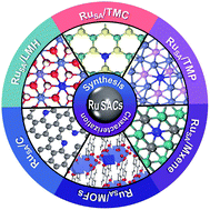
In Ru SACs, the support material plays an important role in anchoring and stabilizing Ru SAs. Therefore, selecting an appropriate catalyst support is vital. In recent years, various supports have been extensively reported for anchoring Ru SAs, such as transition metal chalcogenides (TMCs),23,38,67 transition metal phosphides (TMPs),56,68 carbon materials,22,28,31,69 MXenes,48 metal organic frameworks (MOFs)33 and transition-metal-based layered metal hydroxides (LMHs).55 In the following discussion, we summarize the recent progress in Ru SACs for HER, according to the support categories above.

Transition metal chalcogenide supports

The synergistic effect between the Ru SA site and the support is favorable for HER performance. Therefore, TMCs with high intrinsic catalytic activity are promising supports for Ru SAs. As one of the presentative TMC supports, MoS2 has been widely investigated to serve as the support for Ru SAs. For instance, Wang et al. synthesized RuSA-doped MoS2 with high 2H phase content (Ru@2H–MoS2) by a two-step hydrothermal method.35 The HAADF-STEM images (Fig. 5a–c) showed atomically dispersed Ru atoms mainly located in the position of Mo atoms, which revealed that Ru atoms were mainly embedded in the MoS2 plane by substituting Mo atoms. XANES measurements (Fig. 5d) showed that Ru atoms in Ru@2H–MoS2 were in a cationic form. The FT-EXAFS spectrum of Ru@2H–MoS2 showed a first-shell scattering peak at ∼1.44 Å, smaller than that of Ru foil (2.38 Å) (Fig. 5e). Further, the WT-EXAFS spectrum of Ru@2H–MoS2 exhibited a strong Ru–S signal, apart from the Ru–Ru signal from Ru foil (Fig. 5f). These results consistently indicated the formation of Ru SAs embedded inside the MoS2 lattice, likely through substitution of Mo and stabilization via Ru–S coordination. In HER tests (Fig. 5g and h), the Ru0.10@2H–MoS2 (Rux@2H–MoS2 means x mmol RuCl3·xH2O was used in preparation) showed excellent alkaline HER performance (η10 of 51 mV and b of 64.9 mV dec−1). It also performed well in 1.0 M phosphate-buffered saline (PBS) and 0.5 M H2SO4 with η10 of 137 and 168 mV, respectively. In addition, the good stability of the as-prepared Ru@2H–MoS2 was identified by similar linear-sweep voltammetry (LSV) curves before and after scanning for 3000 cycles.
image file: d2ta03860a-f5.tif
Fig. 5 (a) HAADF-STEM image of Ru0.10@2H–MoS2; (b and c) magnified domains of the dashed rectangles of 1T phase, 2H phase and single Ru atoms (marked by yellow dashed circles) dispersed in the MoS2 plane shown in a. (d) The normalized Ru K-edge XANES spectra, (e) FT-EXAFS spectra and (f) WT-EXAFS spectra of Ru foil and Ru0.10@2H–MoS2. (g) Polarization curves and (h) Tafel plots for 2H–MoS2, Ru0.05@2H–MoS2, Ru0.10@2H–MoS2 and Ru0.12@2H–MoS2 in 1.0 M KOH. Reprinted with permission from ref. 35. Copyright 2021 Elsevier.

Furthermore, various MoS2-based heterostructures have been developed as the supports for anchoring Ru SAs. Taking CC@MoS2/MoP/RuSA as an example, which has been mentioned above, the composite showed excellent alkaline HER activity with a η10 of 45 mV and b of 52.9 mV dec−1.24 The electrodeposited Ru atoms were anchored preferentially on the defect sites of MoS2/MoP (Fig. 6a), which was confirmed by the electron paramagnetic resonance (EPR) spectra in Fig. 6b; the number of defects increased by the phosphorization reaction and significantly decreased after Ru SA deposition. The as-prepared Ru SAs were identified by AC HAADF-STEM measurement (Fig. 6c). The XPS spectra (Fig. 6d) showed that the peaks of Ru 3p for CC@MoS2/MoP/RuSA had higher energy than those for CC@MoS2/MoP/RuNP, indicating the absence of metallic Ru in CC@MoS2/MoP/RuSA. Dual-pathway kinetic analysis (Fig. 6e) clearly illustrated the synergistic effect between MoS2/MoP and Ru SAs; the kinetic current of CC@MoS2/MoP/RuSA was much larger than that of CC@RuNP at the same overpotential, and the free energies on CC@MoS2/MoP/RuSA were all lower than those on CC@RuNP. The optimized structure (Fig. 6f) of MoS2/MoP with one Ru SA isolated in the S-vacancy of MoS2/MoP (MoS2/MoP/RuSA) and its charge density map (Fig. 6g) revealed substantial charge redistribution at the Ru-bonding region of MoS2/MoP/RuSA. The authors explained that both synergistic effect and charge redistribution between the interfaces of MoS2/MoP and Ru SAs modulated the adsorption and desorption of intermediates, promoting the alkaline HER catalytic activity of MoS2/MoP/RuSA, illustrated schematically in Fig. 6h.


image file: d2ta03860a-f6.tif
Fig. 6 (a) Schematic illustration of Ru SAs that were confined in the defects of MoS2/MoP. (b) EPR spectra of CC@MoS2, CC@MoS2/MoP and CC@MoS2/MoP/RuSA. (c) HAADF-STEM image of MoS2/MoP/RuSA. (d) High-resolution XPS spectra of Ru 3p signals for CC@MoS2/MoP/RuNP and CC@MoS2/MoP/RuSA. (e) Electrochemical surface area normalized experimental LSV curves (circles line) of CC@MoS2/MoP/RuSA and CC@RuNP with the best fits (solid line); (f) optimized structure of the top view for MoS2/MoP/RuSA; (g) corresponding charge density maps. (h) Schematic illustration of alkaline HER mechanism for MoS2/MoP/RuSA. Reprinted with permission from ref. 24. Copyright 2021 Elsevier. (i) and (j) HAADF-STEM images of Ru–MoS2–Mo2C NS. (k) ΔGH* of MoS2, Ru–MoS2, MoS2–Mo2C and Ru–MoS2–Mo2C material models. (l) LSV measurements and (m) Tafel slopes of different materials for HER in 1.0 M KOH; (n) chronoamperometric measurement of the Ru–MoS2–Mo2C/TiN and Pt/C on CC for alkaline HER at an initial current response of 40 mA cm−2. Reprinted with permission from ref. 70. Copyright 2021 Elsevier.

In another study, Hoa et al. reported a MoS2–Mo2C heterostructure incorporated with Ru SAs (2.02 at%) and supported by 1D TiN nanorod arrays to form a 3D hierarchical porous material (Ru–MoS2–Mo2C/TiN).70 The HAADF-STEM images (Fig. 6i and j) showed a uniform distribution of atomically dispersed Ru atoms in the MoS2–Mo2C heterostructure. According to DFT calculations, the ΔGH* (Gibbs free energy of H* absorption, in Fig. 6k) of the Ru–MoS2–Mo2C was much closer to 0 than that of MoS2, Ru–MoS2 and MoS2–Mo2C material models, suggesting that Ru–MoS2–Mo2C should achieve the optimal HER performance among them. Fig. 6l and m showed the HER LSV and Tafel curves of different catalysts, among which Ru–MoS2–Mo2C/TiN had the best performance, with a η10 of 25 mV and b of 56 mV dec−1, consistent with the calculated results. The stability for HER was evaluated through chronoamperometry conducted at an initial current of 40 mA cm−2 (Fig. 6n); the results showed that Ru–MoS2–Mo2C/TiN had a current retention of ∼94% after 35 h in 1.0 M KOH, whereas Pt/C had a current retention of 77%, implying that Ru–MoS2–Mo2C/TiN was more stable than Pt/C.

Transition metal phosphide supports

TMPs have emerged recently as a representative class of low-cost HER electrocatalysts. Therefore, they have drawn broad attention as attractive supports for Ru SACs, with the Ru SAs dispersed via coordination with P sites. Wu et al. reported the formation of Ru SAs–Ni2P as mentioned above.37 The HAADF-STEM images (Fig. 7a) demonstrated the isolated distribution of Ru atoms in Ni2P NPs. The as-prepared Ru SAs–Ni2P sample showed high HER catalytic activity, with η10 of 57 and 125 mV and b of 75 and 71 mV dec−1 in alkaline and acidic solutions, respectively (Fig. 7b–e). In particular, 2.20 wt% Ru SAs–Ni2P had a considerably higher mass activity (1134 mA mg−1Ru) than 5 wt% Ru/C (760 mA mg−1Ru) and 20 wt% Pt/C (609 mA mg−1Pt) at an overpotential of 57 mV (Fig. 7f). In addition, during long-term stability tests of the Ru SAs–Ni2P sample, they observed a loss in the current density of 22.1% in 1 M KOH at an overpotential of 57 mV (Fig. 7g), and 23.5% in 0.5 M H2SO4 at an overpotential of 125 mV (Fig. 7h). The operando XANES spectra (Fig. 7i) showed that the oxidation of Ru in the Ru SAs–Ni2P catalyst increased slightly with increasing overpotential to −0.06 or −0.1 V (vs. RHE, reversible hydrogen electrode). Moreover, a new peak at 1.37–1.40 Å (absent in the ex situ result) was observed in the operando FT-EXAFS spectrum (Fig. 7j) for Ru SAs–Ni2P at −0.06 or −0.1 V (vs. RHE). The k-space value of Ru at −0.06 V from the WT-EXAFS spectrum (Fig. 7k) shifted to a lower value (marked by the white arrow) compared with that of the ex situ result. Both the new peak in the FT-EXAFS spectrum and the lower k-space value in the WT-EXAFS spectrum indicated the adsorption of hydroxyl or water molecules on the surfaces of Ru SA sites during HER. Based on the operando XAS results, the authors indicated that the Ru SA sites played an active role in HER and participated in the catalytic process.
image file: d2ta03860a-f7.tif
Fig. 7 (a) AC HADDF-STEM image of 2.20 wt% Ru SAs–Ni2P. (b) LSV curves and (c) Tafel plots of Ni NPs, Ru–Ni NPs, pure Ni2P, 2.20 wt% Ru SAs–Ni2P and 20 wt% Pt/C in 1 M KOH; (d) LSV curves and (e) Tafel plots of Ni NPs, Ru–Ni NPs, pure Ni2P, 2.20 wt% Ru SAs–Ni2P and 20 wt% Pt/C in 0.5 M H2SO4; (f) mass activities of 20 wt% Pt/C, 5 wt% Ru/C, and 2.20 wt% Ru SAs–Ni2P at the overpotential of 57 mV. Time-dependent current density curves for 2.20 wt% Ru SAs–Ni2P catalyst in (g) 1 M KOH at the overpotential of 57 mV and (h) 0.5 M H2SO4 at the overpotential of 125 mV, respectively. (i) Operando XANES spectra at Ru K-edge of 2.20 wt% Ru SAs–Ni2P under different overpotentials (vs. RHE) during HER, and reference standards of Ru foil and RuO2; (j) corresponding k3-weighted FT-EXAFS spectra; (k) WT-EXAFS spectra at Ru K-edge of ex situ and −0.06 V (vs. RHE) for 2.20 wt% Ru SAs–Ni2P. Reprinted with permission from ref. 37. Copyright 2020 Elsevier.

In another study, Shang et al. obtained isolated RuSA-modified FeP by WI combined with phosphorization treatment (Fig. 8a).71 The atomic dispersion of Ru was directly detected by HAADF-STEM (Fig. 8b). The XANES (Fig. 8c) and WT-EXAFS (Fig. 8d) measurements of Ru-modified FeP mainly detected backscattering from Ru–P, indicating the presence of Ru–P4–Fe interface sites. Fig. 8e showed the high HER activity of Ru-modified FeP in 0.5 M H2SO4 solution, i.e., η10 of 62 mV and b of 45 mV dec−1. The good stability of Ru-modified FeP was confirmed through chronopotentiometry conducted over 10 h (Fig. 8f). The fitted average oxidation states of Ru from the operando XANES spectra (Fig. 8g) suggested that the mean valence state of Ru increased in the order of ex situ, open-circuit voltage (OCV) and −80 mV (vs. RHE). The shift of the Ru–P peak in the operando FT-EXAFS spectrum (Fig. 8h) implied the reconstruction of Ru–P bonds during the HER process. Overall, the bond lengthening of isolated Ru–P4–Fe sites under catalytic conditions was demonstrated to be responsible for the improved HER activity of RuSA-modified FeP compared with that of pure FeP.


image file: d2ta03860a-f8.tif
Fig. 8 (a) Illustration of the formation of isolated RuSA-modified FeP. (b) HAADF-STEM image of Ru-modified FeP. (c) Ru K-edge FT-EXAFS curves of Ru-modified FeP, Ru foil and RuO2; (d) WT-EXAFS of Ru-modified FeP and Ru foil. (e) HER polarization curve for Ru-modified FeP, compared with FeP and Pt/C. (f) The chronopotentiometric curve at a current density of 10 mA cm−2. (g) The fitted oxidation states of Ru from XANES spectra and (h) FT-EXAFS spectra of isolated RuSA-modified FeP during HER. Reprinted with permission from ref. 71. Copyright 2020 The Royal Society of Chemistry.

Carbon supports

Owing to their low cost, high electrical conductivity and acceptable corrosion resistance, carbon materials have been extensively used as the supports for Ru SACs. Their electronic structures can be readily modulated by doping with selected heteroatoms (N, P, S, etc.). As a result, Ru SAs are commonly stabilized on carbon materials by bonding with these heteroatoms. For instance, Yu et al. stabilized Ru SAs on B,N co-doped carbon (Ru–N/BC) as mentioned above.26 The HAADF-STEM image (Fig. 9a) indicated the high degree of Ru dispersion at the atomic scale. The XANES spectra (Fig. 9b) showed that the Ru in Ru–N/BC carried more positive charges than any other Ru-based samples; the FT-EXAFS spectra (Fig. 9c) exhibited a dominant peak attributed to Ru–N (or Ru–C) in all Ru supported samples. It suggested a strong metal–support interaction between Ru and N,B co-doped pairs. Moreover, owing to the close-to-zero ΔGH* (Fig. 9d), Ru–N/BC exhibited excellent HER activity with η10 of 51 and 79 mV in alkaline and acidic electrolytes, respectively (Fig. 9e). Fig. 9f showed that Ru–N/BC had a lower η10, Tafel slope and charge transfer resistance (Rct), and a higher exchange current density (j0) and mass activity (MA) compared with other Ru supported samples.
image file: d2ta03860a-f9.tif
Fig. 9 (a) HAADF-STEM images of Ru–N/BC. (b) The normalized Ru K-edge XANES and (c) FT-EXAFS spectra of Ru–N/BC, Ru/BC, Ru–N/C, Ru/C, Ru foil, RuCl3 and RuO2. (d) The calculated ΔGH* for Pt (111), RuO2 (110), Ru (0001), Ru–N/BC, Ru/BC, Ru–N/C and Ru/C. (e) LSV curves (iR compensated) of Ru–N/BC, Ru/BC, Ru–N/C, Ru/C and commercial Pt/C (20 wt%) electrodes in N2-saturated 1 M KOH solution at a sweep rate of 5 mV s−1; (f) radar patterns of η10, mass activity (MA) (at −0.100 V), Tafel slope, j0 and charge transfer resistance (Rct) for Ru–N/BC, Ru/BC, Ru–N/C and Ru/C in 1 M KOH (left) and 0.5 M H2SO4 (right) solutions. Reprinted with permission from ref. 26. Copyright 2020 The Royal Society of Chemistry. AC HAADF-TEM images of (g) Ru ADC and (h) Ru SAC, respectively, the inset in g is diameter statistical distribution histogram of pure clusters in Ru ADC. (i) Ru XANES spectra and (j) Ru FT-EXAFS spectra of Ru foil, Ru ADC, Ru SAC and RuO2. (k) LSV curves for alkaline HER of Ru ADC, Ru NPs and 20% Pt/C. (l) Stability tests of Ru ADC, including CV cyclic curves and chronoamperometric curve. Reprinted with permission from ref. 22. Copyright 2021 John Wiley and Sons.

Cao et al. fabricated Ru ADC and Ru SAC supported on S–CB as mentioned above.22 The HAADF-STEM image of Ru ADC (Fig. 9g) showed that atomically dispersed nanoclusters and abundant SAs were simultaneously present on the carbon support, and the average size of the monodispersed Ru sub-nanoclusters was ∼1.5 nm (inset in Fig. 9g). The HAADF-STEM image of Ru SAC (Fig. 9h) showed isolated Ru atoms dispersed on the support. The XANES spectra (Fig. 9i) showed that positive charges from the Ru element were observed in both Ru SAC and Ru ADC. The absence of Ru–Ru bonds in the FT-EXAFS spectra of both Ru SAC and Ru ADC (Fig. 9j) further confirmed the formation of atomically dispersed Ru on the S–CB support. In addition, the Ru ADC showed a low η10 (18 mV) (Fig. 9k) and b (41 mV dec−1) in 1 M KOH solution, which were much lower than those of 20% Pt/C (η10 = 46 mV, b = 53 mV dec−1). The good alkaline HER performance was ascribed to the synergistic effect of Ru SAs and Ru oxide nanoclusters, which enhanced water molecule capture and dissociation by coupling sites and hydrogen release by SAs. Furthermore, the Ru ADC exhibited high durability for 60 h with a negligible decrease in the current density (Fig. 9l), and its LSV curve after 5000 cycles was almost the same as that recorded in the initial state (inset in Fig. 9l).

Layered metal hydroxide supports

LMHs with abundant negatively charged hydroxyl groups demonstrate great potential as supports for Ru SACs applied in alkaline HER because of their confinement effect on the loaded SAs and strong interaction between the surface hydroxyl groups and SAs. For example, Chen et al. synthesized atomic Ru-loaded Ni(OH)2 nanoribbons (R–NiRu) with the atomic Ru loading up to ∼7.7 wt% via a one-step hydrothermal method.34 In the HAADF-STEM image (Fig. 10a), the lattice spacing corresponded to the (015) crystal plane of α–Ni(OH)2, and the Ru atoms (marked with red circles) showed higher brightness than Ni and O atoms.72 The FT-EXAFS (Fig. 10b) and WT-EXAFS (Fig. 10c and d) results verified that Ru was atomically dispersed on the surface of Ni(OH)2 in R–NiRu, while both Ru SAs and particles were present in S–NiRu (Ru-loaded Ni(OH)2 NSs). Taking advantage of the synergistic effect between Ru SAs and nanoribbon morphology of Ni(OH)2, R–NiRu had a η10 of 16 mV and b of 40 mV dec−1 in 1.0 M KOH solution (Fig. 10e and f). The results of CV conducted for 5000 cycles (Fig. 10g) demonstrated the good catalytic stability of R–NiRu.
image file: d2ta03860a-f10.tif
Fig. 10 (a) HAADF-STEM image of R–NiRu and most Ru atoms are marked by red dotted circles. (b) Ru K-edge FT-EXAFS spectra of R–NiRu, S–NiRu, RuO2 and Ru metal; K2 weighted WT-EXAFS spectra of (c) R–NiRu and (d) S–NiRu, respectively. (e) LSV comparative tests and (f) corresponding Tafel slopes of R–NiRu, S–NiRu, NF (Ni foam) and commercial Pt/C. (g) Comparison of LSV plots between the R–NiRu initial and after 5000 CV cycles test. Reprinted with permission from ref. 34. Copyright 2021 John Wiley and Sons.

MXene supports

MXenes are a class of 2D transition metal carbides/nitrides that have exceptional properties, including excellent electronic conductivity, catalytically active basal planes, hydrophilic surface functionalities (such as –O, –OH and –F groups) and a unique layered structure.73,74 These properties make MXenes excellent candidates for appropriate supports for Ru SACs. Ramalingam et al. used a titanium carbide (Ti3C2Tx) MXene as a solid support for N,S-coordinated Ru SAC (RuSA–N–S–Ti3C2Tx).75 The Ru SAs were stabilized on the MXene support by forming Ru–N and Ru–S bonds originating from successive mixing of Ti3C2Tx, RuCl3·xH2O and thiourea, followed by freeze drying and annealing (Fig. 11a). In the HAADF-STEM image (Fig. 11b), the small homogeneously distributed bright dots confirmed the presence of atomically dispersed Ru atoms isolated on the Ti3C2Tx support. The FT-EXAFS (Fig. 11c) and XANES (Fig. 11d) results revealed the atomic dispersion of Ru on the Ti3C2Tx MXene support and the strong electronic coupling between Ru SA and Ti3C2Txvia N and S atoms. The resultant RuSA–N–S–Ti3C2Tx catalyst had a η10 of 76 mV and b of 90 mV dec−1 in 0.5 M H2SO4 (Fig. 11e and f), and η10 of 99 and 275 mV in 0.5 M NaOH and 0.5 M Na2SO4, respectively, indicating the high HER performance of the RuSA–N–S–Ti3C2Tx catalyst over a wide pH range. In addition, RuSA–N–S–Ti3C2Tx showed high TOF values (0.52, 0.87 and 1.50H2 s−1 at 100, 150 and 200 mV, respectively), comparable with reported metal-based HER catalysts in the acidic electrolyte (Fig. 11g).
image file: d2ta03860a-f11.tif
Fig. 11 (a) Schematic illustration of the RuSA–N–S–Ti3C2Tx synthetic route. (b) HAADF-STEM image of RuSA–N–S–Ti3C2Tx. Scale bar, 2 nm. (c) FT-EXAFS spectra and (d) the normalized Ru K-edge XANES spectra of Ru foil, RuO2 and RuSA–N–S–Ti3C2Tx. (e) HER polarization curves of bare carbon paper (CP), Ti3C2Tx, N–S–Ti3C2Tx, RuSA–Ti3C2Tx, Pt and RuSA–N–S–Ti3C2Tx in 0.5 M H2SO4; inset: the magnified view of RuSA–N–S–Ti3C2Tx; (f) Tafel plots corresponding to e; (g) TOF of the RuSA–N–S–Ti3C2Tx catalyst compared with previously reported metal-based HER electrocatalysts. Reprinted with permission from ref. 75. Copyright 2019 John Wiley and Sons.

Metal organic framework supports

MOFs are a class of emerging porous crystalline materials composed of various organic ligands and metal centers. Benefiting from their broad tunability, well-defined porous structure and large specific surface area, MOFs are often adopted as supports for designing Ru SACs. For example, Sun et al. developed the Ni–BDC MOF and introduced atomically dispersed Ru into it (named NiRux–BDC, where x represents the molar ratio of Ni and Ru) as mentioned above.33 The EDXS results of NiRu0.13–BDC in Fig. 12a demonstrated that C, O, Ni and Ru were distributed uniformly. The XANES spectra (Fig. 12b) indicated that the valence of Ru in NiRu0.13–BDC was between 0 and +4. The FT-EXAFS spectrum of NiRu0.13–BDC (Fig. 12c) only showed a primary peak at 1.5 Å assigned to the Ru–O bond. These results revealed that the Ru SAs were successfully dispersed in the Ni–BDC. Moreover, the as-synthesized NiRu0.13–BDC showed excellent HER activity over a wide pH range (Fig. 12d–g), specifically delivering a η10 of 36 mV and b of 32 mV dec−1 in 1 M PBS. In addition, NiRu0.13–BDC exhibited high stability with a negligible current decrease after 30 h of chronoamperometry conducted at an overpotential of 50 mV (vs. RHE) in 1M PBS solution (Fig. 12h). According to DFT calculations, adding Ru SAs into the MOF regulated the electronic states of Ni and Ru and the d-band center of Ni (Fig. 12i), resulting in enhanced water adsorption by Ru in NiRu0.13–BDC (Fig. 12j) and a more thermoneutral ΔGH* by Ni in NiRu0.13–BDC (Fig. 12k), thus improving HER performance.
image file: d2ta03860a-f12.tif
Fig. 12 (a) HAADF-STEM image and the corresponding STEM-EDXS elemental maps of NiRu0.13–BDC. (b) Ru K-edge XANES spectra and (c) FT-EXAFS spectra of NiRu0.13–BDC, Ru foil and RuO2. (d) LSV curves toward HER and (e) Tafel plots of Ni–BDC, NiRu0.09–BDC, NiRu0.13–BDC, NiRu0.21–BDC in 1 M PBS; LSV curves of Ni–BDC, NiRu0.09–BDC, NiRu0.13–BDC, NiRu0.21–BDC toward HER in (f) 1 M KOH and (g) 1 M HCl. (h) Chronoamperometric curves of NiRu0.13–BDC in 1 M PBS. (i) Calculated DOS of Ni in Ni–BDC and NiRu0.13–BDC; (j) the calculated adsorption free energy of water and (k) ΔGH* diagram of Ru in NiRu0.13–BDC compared with Ni in Ni–BDC and NiRu0.13–BDC. Reprinted with permission from ref. 33. Copyright 2021 Nature Publishing Group.

Other supports

Other supports have also been reported for Ru SACs for HER applications. Taking metal NPs as an example, Lai et al. anchored SA sites (M = Ir, Pt, Ru, Pd, Fe and Ni) on heterogeneous support with Co NPs dispersed in N-doped porous carbon (Co/NC) via a general π-electron-assisted strategy. In this preparation, MSA@Co and MSA@NC were simultaneously formed, accelerating OER and HER, respectively (Fig. 13a).30 Fast-FT inverse high-resolution HAADF (FFTI-HAADF) images clearly showed Ru SAs uniformly dispersed on both the NC matrix (Fig. 13b) and Co NP (Fig. 13c) without agglomeration. Among the MSA@Co/NC catalysts, the obtained IrSA@Co/NC showed the highest activity toward HER and OER in an alkaline solution (Fig. 13d), i.e., toward overall water splitting.
image file: d2ta03860a-f13.tif
Fig. 13 (a) Illustration of the working mechanism of the prepared electrodes. FFTI-HAADF images of RuSA (b) on NC and (c) on Co particles. (d) The overall η10 of FeSA@Co/NC, RuSA@Co/NC, NiSA@Co/NC, PdSA@Co/NC, PtSA@Co/NC and IrSA@Co/NC in N2-saturated 1.0 M KOH. Reprinted with permission from ref. 30. Copyright 2019 John Wiley and Sons. (e) AC HAADF-STEM image of Ru SAs/N–Mo2C NSs. (f) XANES spectra and (g) k3-weighted FT-EXAFS spectra for Ru K-edge of Ru NPs/MoO2 NSs, Ru SAs/N–Mo2C NSs and Ru foil. (h) High-resolution XPS spectra of Ru 3d for Ru NPs/MoO2 NSs and Ru SAs/N–Mo2C NSs. (i) HER polarization curves and (j) time-dependent current density curves in 1.0 M KOH. Reprinted with permission from ref. 27. Copyright 2020 Elsevier.

Taking transition metal carbides as another example, Mo2C has been widely applied as a support for active metal catalysts in many reactions due to its outstanding chemical, mechanical and thermal stability.76,77 Yu et al. reported Ru SAs dispersed on N-doped Mo2C NSs as mentioned above.27 Isolated Ru SAs were confirmed by AC HAADF-STEM (Fig. 13e), XAFS (XANES and EXAFS in Fig. 13f and g, respectively) and XPS (Fig. 13h) measurements. When the as-prepared Ru SAs/N–Mo2C NSs were tested as an electrocatalyst, they showed obvious HER activity with a η10 of 43 mV (Fig. 13i) and long-term stability at high current densities (Fig. 13j) in 1.0 M KOH.

Phosphorus nitride (PN) consists of a three-dimensional framework of corner-sharing PN4 tetrahedral units.78 Compared to the uniform electron density of carbon, the electron density of the carbon-free PN matrix is extremely inhomogeneous.79 This property could greatly facilitate the activation of reaction substrates when the SAs are anchored on the PN matrix. Hence, PN has been suggested as the ideal support for Ru SACs. For instance, Yang et al. anchored Ru SAs on a PN matrix (RuSA@PN) by strong coordination interactions between the d orbitals of Ru and the lone pair electrons of N.80 DFT calculations demonstrated that the ΔGH* of the Ru SAs on PN was much closer to zero compared with those of Ru/C and Ru SAs supported on carbon or C3N4, thus considerably facilitating the HER performance. As a result, RuSA@PN delivered a η10 of 24 mV and b of 38 mV dec−1 in 0.5 M H2SO4 in their experiments.

Recently, Li et al. fabricated g–C3N4–C–TiO2 nanospheres with oxygen-rich vacancies for anchoring abundant Ru SAs (12.4 wt%).81 They proposed a configuration with each Ru atom bonded with two oxygen and two nitrogen atoms and coupled with adjacent oxygen vacancies on the g–C3N4–C–TiO2 nanosphere. The as-prepared RuSA/g–C3N4–C–TiO2 had a η10 of 107 mV and TOF of 0.28H2 s−1 at 100 mV toward alkaline HER. DFT calculations revealed that the remaining oxygen vacancies benefited the water dissociation, while Ru SAs increased the hydrogen adsorption strength. Therefore, oxygen vacancies and Ru SAs cooperatively enhanced H2 evolution in alkaline media.

Summary

Ru SACs on various supports have demonstrated promising potential for HER electrocatalysis. Such supports should have intrinsic catalytic activity, excellent electrical conductivity and a large specific surface area. Among the above-mentioned supports, TMCs and TMPs have high intrinsic catalytic activity, and their hybrids with Ru SAs have been shown to have synergetic catalytic performance; carbon materials have excellent conductivity, and they can easily stabilize Ru SAs via their doping heteroatoms (N, P, S, etc.); LMHs are very suitable supports for alkaline HER; MXenes and MOFs have large specific surface areas. The optimization of support materials should continue to provide more Ru SA anchoring sites, enhance the binding force with Ru SAs to increase stability, and take full advantage of synergistic effect between Ru SAs and supports. Comparison of the reported electrocatalytic HER activity of Ru SACs with different supports is shown in Table 1. For clarification, η10 of these Ru SACs with different supports in electrolyte of pH = 0, 7 and 14 are displayed in Fig. 14a, b and c, respectively. There are more Ru SACs suitable for alkaline electrolytes than acidic ones, and their HER performance in alkalis is also better than those in acids. In acidic conditions, the best HER activity was achieved using a Ru SAC based on Ni2(OH)2(C8H4O4) (MOF support), followed by N–Ti3C2Tx (MXene support), PN, NC NWs (carbon support) and CoP/CDs (TMP support). In alkaline conditions, most Ru SACs showed high HER activity, and they were fabricated with various support types, including TMC, TMP, carbon, MXene, MOF and LMH supports. However, the research on Ru SACs in neutral conditions is lacking and the reported catalytic activity is still very low. Therefore, the research and development of Ru SACs suitable for neutral electrolytes is considered a key research direction in the future.
Table 1 Comparison of the reported electrocatalytic HER activity of Ru SACs with different supportsa
Support Electrolyte η 10 (mV) b (mV dec−1)
a CNT: multiwalled carbon nanotube; CDs: carbon dots; ECM: edge-rich carbon matrix; NPG: N,P co-doped graphene; rGO: reduced graphene oxide; D–NiFe LDH: defective Ni–Fe layered double hydroxide.
TMC 2H–MoS235 0.5 M H2SO4 167 77.5
1 M KOH 51 64.9
1 M PBS 137 81.1
MoS267 1 M KOH 76 21
Nanoporous MoS238 1 M KOH 30 31
MoS2/CC23 1 M KOH 41 114
MoS2/CNT82 1 M KOH 50 62
CC@MoS2/MoP24 1 M KOH 45 52.9
MoS2–Mo2C/TiN70 1 M KOH 25 56
TMP Ni2P37 0.5 M H2SO4 125 71
1 M KOH 57 75
FeP71 0.5 M H2SO4 125 45
Ni5P436 1 M KOH 54 52
CoP/CDs56 0.5 M H2SO4 49 51.6
1 M KOH 51 73.4
Carbon N/BC26 0.5 M H2SO4 79 62
1 M KOH 51 44
NC NWs28 0.5 M H2SO4 29 28
0.1 M KOH 47 14
1 M KOH 12
S–CB22 1 M KOH 18 41
ECM69 0.5 M H2SO4 63 47
1 M KOH 83 59
NPG83 0.5 M H2SO4 93 59.4
C3N484 0.5 M H2SO4 140 57
C3N4/rGO59 0.5 M H2SO4 80 55
MXene N–Ti3C2Tx48 0.5 M H2SO4 23 42
1 M KOH 27 29
1 M PBS 81
N–S–Ti3C2Tx75 0.5 M H2SO4 76 90
0.5 M NaOH 99
0.5 M NasSO4 275
MOF Ni2(OH)2(C8H4O4)33 1 M HCl 13
1 M KOH 34 32
1 M PBS 36 32
LMH R–NiRu34 1 M KOH 16 40
D–NiFe LDH55 1 M KOH 18 29
Other Co/NC30 1 M KOH ∼190 210
N–Mo2C27 1 M KOH 43 38.67
PN80 0.5 M H2SO4 24 38
G–C3N4–C–TiO281 0.5 M H2SO4 112 83
1 M KOH 107 65
N–TiO2/C32 1 M KOH 159 75


image file: d2ta03860a-f14.tif
Fig. 14 Overpotentials of reported Ru SACs with different supports at (a) j of 10 mA cm−2 in electrolyte of a pH = 0, (b) pH = 7 and (c) pH = 14.

Conclusion and perspectives

As the most promising renewable energy source, H2 is expected to play an important role in alleviating the increasingly severe energy and environmental crises. To achieve large-scale hydrogen production as soon as possible, researchers have performed many studies on high-efficiency HER catalysts in recent years. SACs are effective and low-cost alternatives to traditional catalysts. Their maximum atom utilization efficiency, unique quantum-size effect and strong interaction with the support enable excellent catalytic activity, selectivity and stability. Compared with the most widely studied Pt SACs, Ru SACs have more extensive application prospects because of their lower cost and competitive HER catalytic performance.

Various synthesis strategies (e.g., WI, electrodeposition, PR and high-temperature pyrolysis) have been proposed and conducted to effectively produce Ru SACs and tailor their catalytic performance. However, the suitability of these methods for upscaling to industrial production has yet to be demonstrated.

As to the characterization techniques, AC-TEM, XAS and XPS are used to identify isolated Ru SAs at the atomic level and understand the unsaturated coordination environment and local electronic structure of Ru SAs. Combining such characterization methods is vital for revealing the size, distribution and coordination of Ru SAs in both micro and macro scales to confirm the successful fabrication of Ru SACs. However, it is still challenging to comprehensively characterize specific changes in Ru SACs during HER.

Considering the catalytic performance of Ru SACs supported on different substrates (e.g., TMCs, TMPs, carbon materials, MXenes, MOFs and LMHs) for HER applications, it is found that most Ru SACs have excellent HER performance in alkaline electrolytes, while some perform well in acidic electrolytes, but few show good performance in neutral electrolytes. For practical application, it is effective to choose inexpensive supports for anchoring Ru SAs, thereby balancing the cost and catalytic performance is necessary to promote the application of Ru SACs for HER. Despite the significant progress in the development of Ru SACs in recent years, there are still some key challenges before these materials are viable for practical HER applications at industrial scales.

(1) Developing Ru SACs for neutral solutions

In electrolytic hydrogen production systems, the use of neutral electrolyte is beneficial to the stability and safety of the system. Therefore, the development of catalysts suitable for neutral conditions is conducive to the industrialization of HER. Among the current studies, most of them mainly focused on improving the HER performance of Ru SACs in alkaline electrolytes, some performed in acidic electrolytes, and only a few used neutral electrolytes. In addition, the related HER performance for neutral conditions has not been adequate for industrial HER applications. Therefore, it is significant to develop effective strategies for enhancing the HER performance of Ru SACs in neutral conditions or develop new high-activity Ru SACs suitable for neutral electrolytes.

(2) Accurate measurements and improved SA stability

Due to the high surface energy of SAs, SAs tend to aggregate into nanoclusters or NPs on the support surface, especially under high metal loading or high-temperature conditions.85 Therefore, compared with other catalysts, SACs are more sensitive to environment and may degrade easier during storage. However, the current methods of studying the stability of HER catalysts, e.g., CV conducted over thousands of cycles, and chronoamperometry or chronopotentiometry over a few hours, only consider the influence of the catalytic process but neglect the storage time and ambient environment. Therefore, establishing an accelerated laboratory measurement for accurately evaluating the storage aging failure time of SACs is urgently required. In addition, the interaction between the SAs and the substrate is important in achieving uniform distribution and increasing the stability of SACs, based on many previous studies.50,86 Therefore, it is meaningful to further explore effective strategies to generate specific SA anchoring sites with strong interactions (e.g., vacancies and coordination of non-metal ions) on suitable substrates to enhance the stability.

(3) Increasing Ru SA loading

In most studies, the RuSA loading in Ru SACs is not high enough to achieve sufficient catalytic activity for commercial HER applications, which is ascribed to the tendency of SAs to agglomerate and the limited number of effective anchoring sites on the supports. Hence, stronger coordination environment and more SA anchoring sites are required to increase the RuSA loading. In addition, theoretical modeling and simulation can assist the design of Ru SACs with high RuSA loading. However, a previous research has also demonstrated that a high loading Ru SACs (12.4 wt%) obtained by anchoring RuSA on oxygen-rich vacancies showed no improvement in catalytic activity when compared to other Ru SACs with lower loading in other studies.81 Therefore, it is worth deeply exploring the relationship between the loading of Ru SAs on different supports and their final catalytic activity for HER.

(4) Achieving a more comprehensive understanding

The lack of a comprehensive understanding of the electronic structure and catalytic mechanism of SA sites is another major challenge for the development of Ru SACs. At present, advanced characterization techniques, such as AC-TEM, XAS and XPS, have been widely used to study the local coordination environment of isolated Ru SAs. However, effective characterization methods are still needed to study the structural changes of Ru SAs during catalytic process and their relationship with catalytic activity. In recent years, operando XAS characterization has been applied to analyze Ru SACs. This method can characterize changes in the SA coordination environment during catalytic process, but there is still a lack of knowledge regarding their correlation with catalytic mechanism. Therefore, more efforts should be devoted to developing advanced in situ/operando characterization strategies and suitable theoretical modeling methods to identify the catalytic mechanism of Ru SACs at the atomic level.

Conflicts of interest

There are no conflicts to declare.

Acknowledgements

This work was supported by the Shenzhen University Outstanding Young Teacher Training Program, Shenzhen Peacock Plan (Grant No. KQTD2016053112042971), the Educational Commission of Guangdong Province project (Key program, Grant no. 2020ZDZX3041), the Guangdong Basic and Applied Basic Research Foundation (Grant No. 2020A1515110333), the Science, Technology and Innovation Commission of Shenzhen Municipality (Grant No. JCYJ20200109105422876), and the National Natural Science Foundation of China (Grant No. 22109108). The authors would like to thank Shiyanjia Lab (http://www.shiyanjia.com) for professional editing.

References

  1. Z. Li, J. Feng, S. Yan and Z. Zou, Nano Today, 2015, 10, 468–486 CrossRef CAS.
  2. S.-Y. Bae, J. Mahmood, I.-Y. Jeon and J.-B. Baek, Nanoscale Horiz., 2020, 5, 43–56 RSC.
  3. J. A. Turner, Science, 2004, 305, 972–974 CrossRef CAS PubMed.
  4. S. Chu and A. Majumdar, Nature, 2012, 488, 294–303 CrossRef CAS PubMed.
  5. Y. Zhu, Q. Lin, Y. Zhong, H. A. Tahini, Z. Shao and H. Wang, Energy Environ. Sci., 2020, 13, 3361–3392 RSC.
  6. J. Zhu, L. Cai, X. Yin, Z. Wang, L. Zhang, H. Ma, Y. Ke, Y. Du, S. Xi, A. T. S. Wee, Y. Chai and W. Zhang, ACS Nano, 2020, 14, 5600–5608 CrossRef CAS PubMed.
  7. https://www.dailymetalprice.com/metalpricecharts.php?https://www.dailymetalprice.com/metalpricecharts.php?c=ir%26u=oz%26d=10.
  8. J. Mahmood, F. Li, S.-M. Jung, M. S. Okyay, I. Ahmad, S.-J. Kim, N. Park, H. Y. Jeong and J.-B. Baek, Nat. Nanotechnol., 2017, 12, 441–446 CrossRef CAS PubMed.
  9. W. Wang, J. Peng, L. Yang, Q. Liu, Y. Wang and H. Liu, Int. J. Electrochem. Sci., 2020, 15, 11769–11778 CrossRef CAS.
  10. J. Creus, J. De Tovar, N. Romero, J. Garcia-Anton, K. Philippot, R. Bofill and X. Sala, Chemsuschem, 2019, 12, 2493–2514 CrossRef CAS PubMed.
  11. Y. Zheng, Y. Jiao, Y. Zhu, L. H. Li, Y. Han, Y. Chen, M. Jaroniec and S.-Z. Qiao, J. Am. Chem. Soc., 2016, 138, 16174–16181 CrossRef CAS PubMed.
  12. J. Wang, Z. Wei, S. Mao, H. Li and Y. Wang, Energy Environ. Sci., 2018, 11, 800–806 RSC.
  13. Y. Yang, Y. Yu, J. Li, Q. Chen, Y. Du, P. Rao, R. Li, C. Jia, Z. Kang, P. Deng, Y. Shen and X. Tian, Nano-Micro Lett., 2021, 13, 160 CrossRef CAS PubMed.
  14. C. Zhang, J. Sha, H. Fei, M. Liu, S. Yazdi, J. Zhang, Q. Zhong, X. Zou, N. Zhao, H. Yu, Z. Jiang, E. Ringe, B. I. Yakobson, J. Dong, D. Chen and J. M. Tour, ACS Nano, 2017, 11, 6930–6941 CrossRef CAS PubMed.
  15. S. Liu, Y. Wang, S. Wang, M. You, S. Hong, T.-S. Wu, Y.-L. Soo, Z. Zhao, G. Jiang, J. Qiu, B. Wang and Z. Sun, ACS Sustainable Chem. Eng., 2019, 7, 6813–6820 CrossRef CAS.
  16. F. Zhang, Y. Zhu, Q. Lin, L. Zhang, X. Zhang and H. Wang, Energy Environ. Sci., 2021, 14, 2954–3009 RSC.
  17. J. Zhu, Y. Tu, L. Cai, H. Ma, Y. Chai, L. Zhang and W. Zhang, Small, 2021, 18, 2104824 CrossRef PubMed.
  18. H. Zhang, G. Liu, L. Shi and J. Ye, Adv. Energy Mater., 2018, 8, 1701343 CrossRef.
  19. J. Liu, ACS Catal., 2017, 7, 34–59 CrossRef CAS.
  20. L. Cao, Q. Luo, J. Chen, L. Wang, Y. Lin, H. Wang, X. Liu, X. Shen, W. Zhang, W. Liu, Z. Qi, Z. Jiang, J. Yang and T. Yao, Nat. Commun., 2019, 10, 4849 CrossRef PubMed.
  21. G. Li, H. Duan, W. Cheng, C. Wang, W. Hu, Z. Sun, H. Tan, N. Li, Q. Ji, Y. Wang, Y. Lu and W. Yan, ACS Appl. Mater. Interfaces, 2019, 11, 45561–45567 CrossRef CAS PubMed.
  22. D. Cao, J. Wang, H. Xu and D. Cheng, Small, 2021, 17, 2101163 CrossRef CAS PubMed.
  23. D. Wang, Q. Li, C. Han, Z. Xing and X. Yang, Appl. Catal., B, 2019, 249, 91–97 CrossRef CAS.
  24. J. Li, C. Zhang, H. Ma, T. Wang, Z. Guo, Y. Yang, Y. Wang and H. Ma, Chem. Eng. J., 2021, 414, 128834 CrossRef CAS.
  25. T. Li, J. Liu, Y. Song and F. Wang, ACS Catal., 2018, 8, 8450–8458 CrossRef CAS.
  26. Y. Yu, S. Yang, M. Dou, Z. Zhang and F. Wang, J. Mater. Chem. A, 2020, 8, 16669–16675 RSC.
  27. J. Yu, A. Wang, W. Yu, X. Liu, X. Li, H. Liu, Y. Hu, Y. Wu and W. Zhou, Appl. Catal., B, 2020, 277, 119236 CrossRef CAS.
  28. B. Lu, L. Guo, F. Wu, Y. Peng, J. E. Lu, T. J. Smart, N. Wang, Y. Z. Finfrock, D. Morris, P. Zhang, N. Li, P. Gao, Y. Ping and S. Chen, Nat. Commun., 2019, 10, 631 CrossRef CAS PubMed.
  29. H. Tao, C. Choi, L.-X. Ding, Z. Jiang, Z. Hang, M. Jia, Q. Fan, Y. Gao, H. Wang, A. W. Robertson, S. Hong, Y. Jung, S. Liu and Z. Sun, Chem, 2019, 5, 204–214 CAS.
  30. W.-H. Lai, L.-F. Zhang, W.-B. Hua, S. Indris, Z.-C. Yan, Z. Hu, B. Zhang, Y. Liu, L. Wang, M. Liu, R. Liu, Y.-X. Wang, J.-Z. Wang, Z. Hu, H.-K. Liu, S.-L. Chou and S.-X. Dou, Angew. Chem., 2019, 58, 11868–11873 CrossRef CAS PubMed.
  31. L. Bai, Z. Duan, X. Wen, R. Si, Q. Zhang and J. Guan, ACS Catal., 2019, 9, 9897–9904 CrossRef CAS.
  32. B. Yan, D. Liu, X. Feng, M. Shao and Y. Zhang, Adv. Funct. Mater., 2020, 30, 2003007 CrossRef CAS.
  33. Y. Sun, Z. Xue, Q. Liu, Y. Jia, Y. Li, K. Liu, Y. Lin, M. Liu, G. Li and C.-Y. Su, Nat. Commun., 2021, 12, 1369 CrossRef CAS PubMed.
  34. X. Chen, J. Wan, J. Wang, Q. Zhang, L. Gu, L. Zheng, N. Wang and R. Yu, Adv. Mater., 2021, 33, 2104764 CrossRef CAS PubMed.
  35. J. Wang, W. Fang, Y. Hu, Y. Zhang, J. Dang, Y. Wu, B. Chen, H. Zhao and Z. Li, Appl. Catal., B, 2021, 298, 120490 CrossRef CAS.
  36. Q. He, D. Tian, H. Jiang, D. Cao, S. Wei, D. Liu, P. Song, Y. Lin and L. Song, Adv. Mater., 2020, 32, 1906972 CrossRef CAS PubMed.
  37. K. Wu, K. Sun, S. Liu, W.-C. Cheong, Z. Chen, C. Zhang, Y. Pan, Y. Cheng, Z. Zhuang, X. Wei, Y. Wang, L. Zheng, Q. Zhang, D. Wang, Q. Peng, C. Chen and Y. Li, Nano Energy, 2021, 80, 105467 CrossRef CAS.
  38. K. Jiang, M. Luo, Z. Liu, M. Peng, D. Chen, Y.-R. Lu, T.-S. Chan, F. M. F. de Groot and Y. Tan, Nat. Commun., 2021, 12, 1687 CrossRef CAS PubMed.
  39. R. Lang, X. Du, Y. Huang, X. Jiang, Q. Zhang, Y. Guo, K. Liu, B. Qiao, A. Wang and T. Zhang, Chem. Rev., 2020, 120, 11986–12043 CrossRef CAS PubMed.
  40. S. K. Kaiser, Z. Chen, D. F. Akl, S. Mitchell and J. Perez-Ramirez, Chem. Rev., 2020, 120, 11703–11809 CrossRef CAS PubMed.
  41. D. Zhao, Z. Zhuang, X. Cao, C. Zhang, Q. Peng, C. Chen and Y. Li, Chem. Soc. Rev., 2020, 49, 2215–2264 RSC.
  42. M. Liu, L. Wang, K. Zhao, S. Shi, Q. Shao, L. Zhang, X. Sun, Y. Zhao and J. Zhang, Energy Environ. Sci., 2019, 12, 2890–2923 RSC.
  43. J. Yang, W. Li, D. Wang and Y. Li, Adv. Mater., 2020, 32, 2003300 CrossRef CAS PubMed.
  44. Y. Wang, H. Su, Y. He, L. Li, S. Zhu, H. Shen, P. Xie, X. Fu, G. Zhou, C. Feng, D. Zhao, F. Xiao, X. Zhu, Y. Zeng, M. Shao, S. Chen, G. Wu, J. Zeng and C. Wang, Chem. Rev., 2020, 120, 12217–12314 CrossRef CAS PubMed.
  45. J. Liu, Chemcatchem, 2011, 3, 934–948 CrossRef CAS.
  46. P. D. Nellist and S. J. Pennycook, Adv. Imaging Electron Phys., 2000, 113, 147–203 Search PubMed.
  47. X. Jiao, Z. Chen, X. Li, Y. Sun, S. Gao, W. Yan, C. Wang, Q. Zhang, Y. Lin, Y. Luo and Y. Xie, J. Am. Chem. Soc., 2017, 139, 7586–7594 CrossRef CAS PubMed.
  48. H. Liu, Z. Hu, Q. Liu, P. Sun, Y. Wang, S. Chou, Z. Hu and Z. Zhang, J. Mater. Chem. A, 2020, 8, 24710–24717 RSC.
  49. H. Mullejans and J. Bruley, J. Phys. IV, 1993, 3, 2083–2092 CrossRef CAS.
  50. C.-C. Hou, H.-F. Wang, C. Li and Q. Xu, Energy Environ. Sci., 2020, 13, 1658–1693 RSC.
  51. Y. Wang, J. Mao, X. Meng, L. Yu, D. Deng and X. Bao, Chem. Rev., 2019, 119, 1806–1854 CrossRef CAS PubMed.
  52. N. Martensson, J. Soderstrom, S. Svensson, O. Travnikova, M. Patanen, C. Miron, L. J. Saethre, K. J. Borve, T. D. Thomas, J. J. Kas, F. D. Vila and J. J. Rehr, 15th International Conference on X-Ray Absorption Fine Structure (XAFS), Beijing, PEOPLES R CHINA, 2012 Search PubMed.
  53. A. Mishra, N. Parsai and B. D. Shrivastava, Indian J. Pure Appl. Phys., 2011, 49, 25–29 CAS.
  54. Z. Du, X. Chen, W. Hu, C. Chuang, S. Xie, A. Hu, W. Yan, X. Kong, X. Wu, H. Ji and L.-J. Wan, J. Am. Chem. Soc., 2019, 141, 3977–3985 CrossRef CAS PubMed.
  55. P. Zhai, M. Xia, Y. Wu, G. Zhang, J. Gao, B. Zhang, S. Cao, Y. Zhang, Z. Li, Z. Fan, C. Wang, X. Zhang, J. T. Miller, L. Sun and J. Hou, Nat. Commun., 2021, 12, 4587 CrossRef CAS PubMed.
  56. H. Song, M. Wu, Z. Tang, J. S. Tse, B. Yang and S. Lu, Angew. Chem., 2021, 60, 7234–7244 CrossRef CAS PubMed.
  57. B. Yu, H. Li, J. White, S. Donne, J. Yi, S. Xi, Y. Fu, G. Henkelman, H. Yu, Z. Chen and T. Ma, Adv. Funct. Mater., 2020, 30, 1905665 CrossRef CAS.
  58. J. Liu, Y. Liu, N. Liu, Y. Han, X. Zhang, H. Huang, Y. Lifshitz, S.-T. Lee, J. Zhong and Z. Kang, Science, 2015, 347, 970–974 CrossRef CAS PubMed.
  59. Y. Peng, W. Pan, N. Wang, J.-E. Lu and S. Chen, Chemsuschem, 2018, 11, 130–136 CrossRef CAS PubMed.
  60. S. Yang, Y. Gong, J. Zhang, L. Zhan, L. Ma, Z. Fang, R. Vajtai, X. Wang and P. M. Ajayan, Adv. Mater., 2013, 25, 2452–2456 CrossRef CAS PubMed.
  61. Z. Geng, Y. Liu, X. Kong, P. Li, K. Li, Z. Liu, J. Du, M. Shu, R. Si and J. Zeng, Adv. Mater., 2018, 30, 1803498 CrossRef PubMed.
  62. J. Lee, A. Kumar, T. Yang, X. Liu, A. R. Jadhav, G. H. Park, Y. Hwang, J. Yu, C. T. K. Nguyen, Y. Liu, S. Ajmal, M. G. Kim and H. Lee, Energy Environ. Sci., 2020, 13, 5152–5164 RSC.
  63. X. Tian, P. Zhao and W. Sheng, Adv. Mater., 2019, 31, 1808066 CrossRef PubMed.
  64. Y. Li, H. Wang, L. Xie, Y. Liang, G. Hong and H. Dai, J. Am. Chem. Soc., 2011, 133, 7296–7299 CrossRef CAS PubMed.
  65. N. Mahmood, Y. Yao, J.-W. Zhang, L. Pan, X. Zhang and J.-J. Zou, Adv. Sci., 2018, 5, 1700464 CrossRef PubMed.
  66. L. Shang, T. Bian, B. Zhang, D. Zhang, L.-Z. Wu, C.-H. Tung, Y. Yin and T. Zhang, Angew. Chem., 2014, 53, 250–254 CrossRef CAS PubMed.
  67. J. Zhang, X. Xu, L. Yang, D. Cheng and D. Cao, Small Methods, 2019, 3, 1900653 CrossRef CAS.
  68. H. Zhang, X. Wu, C. Chen, C. Lv, H. Liu, Y. Lv, J. Guo, J. Li, D. Jia and F. Tong, Chem. Eng. J., 2021, 417, 128069 CrossRef CAS.
  69. H. Zhang, W. Zhou, F. Lu Xue, T. Chen and W. Lou Xiong, Adv. Energy Mater., 2020, 10, 2000882 CrossRef CAS.
  70. V. H. Hoa, D. T. Tran, S. Prabhakaran, D. H. Kim, N. Hameed, H. Wang, N. H. Kim and J. H. Lee, Nano Energy, 2021, 88, 106277 CrossRef CAS.
  71. H. Shang, Z. Zhao, J. Pei, Z. Jiang, D. Zhou, A. Li, J. Dong, P. An, L. Zheng and W. Chen, J. Mater. Chem. A, 2020, 8, 22607–22612 RSC.
  72. J. Chen, S. Ci, G. Wang, N. Senthilkumar, M. Zhang, Q. Xu and Z. Wen, Chemelectrochem, 2019, 6, 5313–5320 CrossRef CAS.
  73. M. Ghidiu, M. R. Lukatskaya, M.-Q. Zhao, Y. Gogotsi and M. W. Barsoum, Nature, 2014, 516, 78–81 CrossRef CAS PubMed.
  74. H.-C. Fu, V. Ramalingam, H. Kim, C.-H. Lin, X. Fang, H. N. Alshareef and J.-H. He, Adv. Energy Mater., 2019, 9, 1970083 CrossRef.
  75. V. Ramalingam, P. Varadhan, H.-C. Fu, H. Kim, D. Zhang, S. Chen, L. Song, D. Ma, Y. Wang, H. N. Alshareef and J.-H. He, Adv. Mater., 2019, 31, 1903841 CrossRef CAS PubMed.
  76. J. Dong, Q. Fu, Z. Jiang, B. Mei and X. Bao, J. Am. Chem. Soc., 2018, 140, 13808–13816 CrossRef CAS PubMed.
  77. S. Yao, X. Zhang, W. Zhou, R. Gao, W. Xu, Y. Ye, L. Lin, X. Wen, P. Liu, B. Chen, E. Crumlin, J. Guo, Z. Zuo, W. Li, J. Xie, L. Lu, C. J. Kiely, L. Gu, C. Shi, J. A. Rodriguez and D. Ma, Science, 2017, 357, 389 CrossRef CAS PubMed.
  78. Q. X. Guo, Q. Yang, L. Zhu, C. Q. Yi and Y. Xie, J. Mater. Res., 2005, 20, 325–330 CrossRef CAS.
  79. T. M. Tolhurst, C. Braun, T. D. Boyko, W. Schnick and A. Moewes, Chem. Eur. J., 2016, 22, 10475–10483 CrossRef CAS PubMed.
  80. J. Yang, B. Chen, X. Liu, W. Liu, Z. Li, J. Dong, W. Chen, W. Yan, T. Yao, X. Duan, Y. Wu and Y. Li, Angew. Chem., 2018, 57, 9495–9500 CrossRef CAS PubMed.
  81. Z. Li, Y. Yang, S. Wang, L. Gu and S. Shao, ACS Appl. Mater. Interfaces, 2021, 13, 46608–46619 CrossRef CAS PubMed.
  82. X. Zhang, F. Zhou, S. Zhang, Y. Liang and R. Wang, Adv. Sci., 2019, 6, 1900090 CrossRef PubMed.
  83. C. Wu, S. Ding, D. Liu, D. Li, S. Chen, H. Wang, Z. Qi, B. Ge and L. Song, Research, 2020, 2020, 5860712 CAS.
  84. Y. Peng, B. Lu, L. Chen, N. Wang, J. E. Lu, Y. Ping and S. Chen, J. Mater. Chem. A, 2017, 5, 18261–18269 RSC.
  85. L. Ma, G. Zhu, D. Wang, H. Chen, Y. Lv, Y. Zhang, X. He and H. Pang, Adv. Funct. Mater., 2020, 30, 2003870 CrossRef CAS.
  86. D. Liu, Q. He, S. Ding and L. Song, Adv. Energy Mater., 2020, 10, 2001482 CrossRef CAS.

This journal is © The Royal Society of Chemistry 2022