
 Open Access Article
 This Open Access Article is licensed under a Creative Commons Attribution-Non Commercial 3.0 Unported Licence
A self-regenerating 3D sponge evaporator with a tunable porous structure for efficient solar desalination†
Patsaya
Anukunwithaya
a,
J. Justin
Koh
b,
Jayven Chee
Chuan Yeo
b,
Siqi
Liu
a,
Xunan
Hou
a,
Nanxue
Liu
ac and
Chaobin
He
 *ab
*ab
aDepartment of Materials Science and Engineering, National University of Singapore, 9 Engineering Drive 1, Singapore 117575, Singapore. E-mail: msehc@nus.edu.sg
bInstitute of Materials Research and Engineering, Agency for Science, Technology and Research (A*STAR), 2 Fusionopolis Way, Innovis, Singapore 138634, Singapore
cDepartment of Materials Science and Engineering, Shanghai University, 99 Shangda Road, Baoshan District, Shanghai 20444, China
First published on 1st July 2022
Abstract
Three-dimensional (3D) solar evaporators are known to possess high evaporation rates, typically exceeding the theoretical limit of conventional evaporators. However, salt fouling remains a challenging issue that plagues 3D evaporators. Herein, we demonstrated bio-based 3D sponge solar evaporators with tailored porous architectures, fabricated with chitosan (CS), agarose (Aga) and multiwalled carbon nanotubes (MW). By merely manipulating the CS to Aga ratio, the pore structures of the sponge can be tuned. As such, an evaporator (5CS/Aga-MW) exhibits impressive evaporation rates of 2.24 and 3.07 kg m−2 h−1, for 30 mm and 60 mm height, based on additional energy gained from the surrounding environment, which exceeded theoretical limit for conventional 2D evaporators. More importantly, evaporation performance using saline water with 3.5% salinity shows a stable evaporation rate of ∼3.04 kg m−2 h−1 for the first 2 days for a height of 60 mm, and ∼2.19 kg m−2 h−1 throughout 10 consecutive days for a height of 30 mm, demonstrating superior anti-salt-fouling ability with an impressive evaporation rate. The excellent performance was attributed to its unique mixed pore structure with low tortuosity, which provided sufficient water supply and the ability to balance out the salt concentration gradient quickly. Such a bottom-up approach in designing 3D evaporators could be an important pathway for the fabrication of efficient 3D-structured evaporators that possess high evaporation performance along with anti-salt-fouling ability.
Introduction
The scarcity of clean drinkable water is becoming an increasingly pressing issue, driven by the perpetual population growth and economic activities, along with its depletion due to pollution.1,2 The situation is especially dire in arid and semi-arid areas due to poor logistical infrastructure, lack of electricity and freshwater supply.3–5 In contrast, solar energy and seawater are abundant in many of these regions, which are valuable resources that can be tapped into. The use of the solar-driven thermal distillation technique to generate clean water from salt, brine, and contaminated water can be traced back to a very early stage in human history until now.6–16 However, only water itself typically exhibits low evaporation rates in the range of 0.2–0.5 kg m−2 h−1 partly due to low energy conversion (<50%) under one sun irradiation.17–21 As such, devices with better photothermal conversion ability, or solar evaporators, have been developed to improve the rate of evaporation and energy conversion efficiency. Enhancing light-to-heat energy conversion by incorporating light-absorbing materials (e.g., carbonaceous materials, semiconducting materials, etc.) has been explored to improve light absorption within the solar spectrum. Even though the water evaporation rate can be approximately improved to the range of 1.00–1.50 kg m−2 h−1.20–24 with enhanced photothermal energy conversion (>80%), the theoretical limit remains at ∼1.7 kg m−2 h−1 given 100% conversion efficiency with minimal energy loss in the conversion process.25 Consequently, some evaporators have been designed into three-dimensional (3D) structures to gain additional energy from the environment in order to exceed the theoretical limit of a 2D evaporating surface.23,26–32 For instance, 3D carbonized sunflower heads have an evaporation rate of 1.51 kg m−2 h−1—,33 while carbonization of naturally occurring materials, such as sunflower heads, mushrooms, wood and food wastes to fabricated solar evaporators is a sustainable approach, and their architectures are limited by how they appear in nature.33–35 In contrast, modified nature-based 3D evaporators have been investigated to achieve better performance.29,30,36 For this reason, a bottom-up approach would allow more tailored designs of morphologies and polymer microstructures, which could alter factors such as water transport ability so as to achieve better performance. For example, the interconnected porous structure and hydrophilicity of the 3D structure of a squid ink–starch hydrogel enhanced water diffusion through pore channels and functionalized polymers, leading to an impressive evaporation rate of 2.62 kg m−2 h−1 beyond the theoretical limit of a 2D evaporator.37Besides the high evaporation rate, having anti-salt-fouling properties is also a key for an efficient solar evaporator. While it is crucial for saltwater to be continuously pumped from the reservoir to the surface for a continuous supply of water, it is also necessary for the highly concentrated salt ions at the evaporating surface to be transported down through diffusion to the low concentrated reservoir. This is to prolong the operation of the solar desalination system without intervention. It has been shown that self-regenerating solar evaporators can be achieved by enhancing ion diffusion, for example, by having large capillary channels.38 Nevertheless, most 3D evaporators require periodic washing for the removal of accumulated salts, which would require human intervention, and interrupt water production.39,40 Impressively, there have been several recent reports on efficient 3D evaporators that exhibit both a high evaporation rate along with anti-salt-fouling ability.41–44 Indeed, there is huge practical potential for 3D-structured evaporators if they are to achieve both a high evaporation rate and anti-salt-fouling ability.
Herein, tailor-made sponge evaporators using chitosan (CS) and agarose (Aga) composited with multiwalled carbon nanotubes (MW) were fabricated. The sponge evaporators were prepared by mechanical blending followed by freeze-casting and drying, yielding monolithic aerogel structures. The 3D-porous structure and hence, water absorption/diffusion/transport, can be tailored through the manipulation of the CS to Aga ratio. All the samples were denoted as 1, 3, 5, and 7CS/Aga-MW for CS to Aga ratios of 1![[thin space (1/6-em)]](https://www.rsc.org/images/entities/char_2009.gif) :1, 3:1, 5:1, and 7:1, respectively. At 60 mm above the water reservoir, 5CS/Aga-MW presented an outstanding water evaporation rate of 3.07 kg m−2 h−1, corresponding to energy utilization of 125.51% under one sun irradiation. More importantly, the unique mixed pore structure, containing both isotropic and anisotropic pores, allows the evaporator to achieve an evaporation rate of 3.04 kg m−2 h−1 under one sun irradiation, which only dipped slightly, starting from the third cycle to 2.62 kg m−2 h−1. Nevertheless, by reducing the height to increase ion diffusion, the 30 mm height evaporator can maintain an evaporation rate of 2.19 kg m−2 h−1 under one sun irradiation for 10 cycles consecutively without observable reduction, exhibiting an extremely stable perpetual desalination system. Furthermore, it was also capable of performing stably at an evaporation rate of 1.96 kg m−2 h−1 in high salinity water (20%), indicating an extremely effective anti-salt fouling ability. Therefore, the bottom-up design provides an effective pathway to fabricate 3D solar evaporators with a tailored porous structure for high and stable water production.
:1, 3:1, 5:1, and 7:1, respectively. At 60 mm above the water reservoir, 5CS/Aga-MW presented an outstanding water evaporation rate of 3.07 kg m−2 h−1, corresponding to energy utilization of 125.51% under one sun irradiation. More importantly, the unique mixed pore structure, containing both isotropic and anisotropic pores, allows the evaporator to achieve an evaporation rate of 3.04 kg m−2 h−1 under one sun irradiation, which only dipped slightly, starting from the third cycle to 2.62 kg m−2 h−1. Nevertheless, by reducing the height to increase ion diffusion, the 30 mm height evaporator can maintain an evaporation rate of 2.19 kg m−2 h−1 under one sun irradiation for 10 cycles consecutively without observable reduction, exhibiting an extremely stable perpetual desalination system. Furthermore, it was also capable of performing stably at an evaporation rate of 1.96 kg m−2 h−1 in high salinity water (20%), indicating an extremely effective anti-salt fouling ability. Therefore, the bottom-up design provides an effective pathway to fabricate 3D solar evaporators with a tailored porous structure for high and stable water production.
Results and discussion
Fabrication of 3D – CS/Aga-MW and mechanical properties
The 3D – CS/Aga-MW evaporators consist of two main natural polymers with 4 wt% of CS/Aga polymer composites. Throughout the experiment, 0.2 wt% MW and 4 wt% glycerol were added as the solar absorber and plasticizer, respectively. During the preparation process, sodium dodecyl sulfate (SDS) was added to improve MW dispersity in the polymer matrix (Fig. S1a†). Typical monolithic 3D – CS/Aga-MWs were prepared by freeze-casting of the hydrogel to induce ice template formation and subsequent freeze-drying for ice-crystal removal as shown in Fig. 1a. A 5CS/Aga-MW shown in Fig. 1b was able to maintain its structural integrity after 24 h of stirring in water at room temperature; after that, the fully swollen sample can be compressed and released without any apparent damage to its structure. In contrast, Aga-MW easily disintegrated in water and was rather fragile (Fig. S1b†). The FT-IR spectra shown in Fig. S1c and d† indicate the intermolecular hydrogen bond between CS and Aga of the CS/Aga-MW composited aerogel, leading to improved stability of the composited sponge evaporators.45–48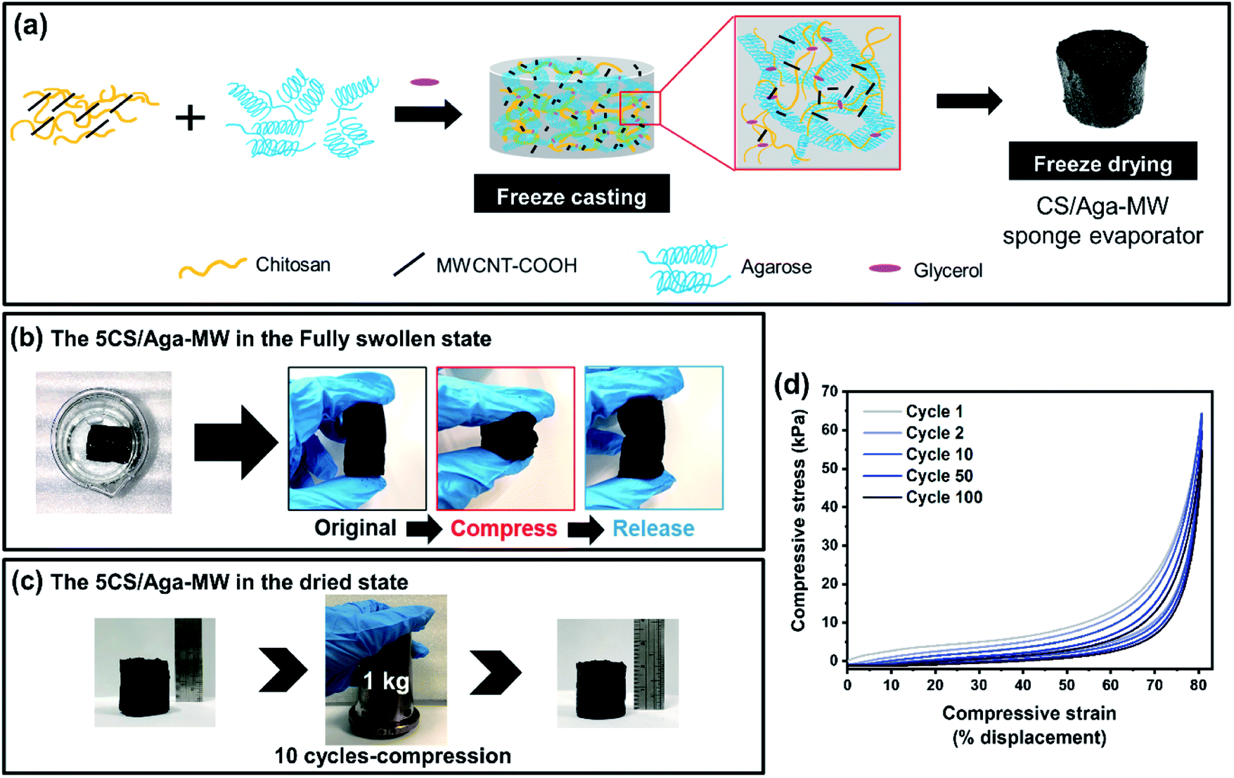 | ||
| Fig. 1 (a) Schematic of the proposed molecular structure and the preparation process, (b) the stability test of 5CS/Aga-MW after 24 h stirring in water at room temperature, and then compression test for swollen 5CS/Aga-MW, (c) the 10 cycles of continuous compression with a 1 kg knob weight of dried 5CS/Aga-MW, and (d) the cyclic compression test of 1, 2, 10, 50, and 100 cycles for dried 5CS/Aga-MW. | ||
In terms of mechanical properties, the aerogel evaporators are extremely lightweight and mechanically robust. For instance, 5CS/Aga-MW has a density of 0.0760 ± 0.01 g cm−3. Fig. 1c shows that 5CS/Aga-MW retained its structural integrity, despite being deformed repeatedly with a 1 kg load 10 times. In addition, Fig. 1d shows the 5CS/Aga-MW cyclic compressive stress–strain curve. As expected, a non-linear hysteresis loop with three segments was observed. The initial segment represents the linear elastic phase (strain 0–15%), followed by the plateau segment with relatively constant stress (strain 15–55%), and lastly, the densification segment with maximum compressive stress observed (55–80%). The mechanical properties of the sample as a function of compression cycles display a steady and gradual reduction within 100 cycles with 80% compression strain, indicating a stable composite aerogel with high elasticity (Video S1†).
The effect of chemical compositions on the interconnected porous structure
The topological structure of the sponge evaporators can be tailored by manipulating the CS and Aga ratio, so as to improve evaporation performance. According to the literature, pure CS and Aga typically form anisotropic porous structures upon the freeze casting process.49–52 However, an isotropic porous structure can also be obtained by the addition of a plasticizer and filler, in this case, glycerol and MW, as shown in Fig. S2a and b.† The porous structures of the various CS/Aga-MW investigated by SEM are presented in Fig. 2. The horizontal cross-sectional SEM image of 1CS/Aga-MW shown in Fig. 2a reveals squarish pore shapes, while that of 7CS/Aga-MW shows a big lamellar structure. The vertical cross-section of SEM images shows that 1CS/Aga-MW has isotropic, non-directional pore structures, in contrast to 7CS/Aga-MW, which has a highly anisotropic, vertically aligned porous structure (Fig. 2b). Whereas the 3 and 5CS/Aga-MW contained intermediate level of CS content, their structures feature both squarish pores and lamellar sheet-like structures. | ||
| Fig. 2 SEM images of 1, 3, 5, and 7CS/Aga-MW in (a) the horizontal and (b) the vertical cross-section, (c) XRD patterns of the swollen state of 1, 3, 5, and 7CS/Aga without MW, (d) optical images and (e) polarized images of the 1, 3, 5, and 7CS/Aga without MW. | ||
The compositional effect on the porous structure of the aerogel can be understood from the microstructure of the polymer composite. To discuss these phenomena, X-ray diffraction (XRD) patterns of CS/Aga shown in Fig. 2c can be explained in term of crystal influence. The XRD patterns show that the %crystallinities of CS/Aga sponges are 7.9, 18, 19.1 and 26.1% for 1, 3, 5 and 7CS/Aga sponge aerogels, respectively. This result suggests that a higher chitosan concentration generally leads to higher crystallinity, whereby most chitosan crystals are trapped by the moving water-ice front upon freezing. The CS crystals then confine themselves to a vertical alignment, and subsequently, the sublimation process on ice removal initiated crystal compaction, thereby inducing a capillary porous structure.53,54 The formation of different pore structures with different CS and Aga ratios is illustrated in Fig. S3.†
Further conformational formation of CS crystals and their corresponding morphologies come from an optical microscope study of freeze-dried CS/Aga films without the addition of MWCNTs (Fig. 2d and e), where the birefringent from polarized microscopy indicates ordered CS crystalline domains. At a lower concentration of CS (i.e., 1CS/Aga), the CS crystals are apparently less and randomly scattered in the composited film. Increased CS in 3CS/Aga led to increased CS crystal formation in the CS crystalline network. For 5CS/Aga and 7CS/Aga, the amounts of CS crystals are more apparent and they are arranged to form the walls of the networks with well-defined lamellar morphology, whereas CS crystals form the core of the lamellar strucutre and agarose sits on the surface of the CS, interacting with water.47,55,56 In addition, the formation of water-impenetrable CS crystals during the freeze-drying process would act as physical crosslinks, providing the monolithic sponge evaporator with mechanical robustness. Also, the formation of the CS crystals during the freeze-drying process maintains their corresponding pore structures in the CS/Aga composited aerogel, which would ultimately provide mechanical strength and affect water diffusion and transport to the evaporating surface, thereby influencing the evaporation rate and self-regeneration ability.
Water diffusion/transport effect toward water evaporation efficiency
As shown in Fig. 3a, the water evaporation rates for bulk water, 1, 3, 5, and 7CS/Aga-MW were measured to be 0.51, 0.92, 1.27, 1.48 and 0.89 kg m−2 h−1 under one sun irradiation, respectively. Since the evaporator height was ∼0 mm above the reservoir, the evaporation performance was mainly affected by factors such as heat localization, water transport, and possibly lower vaporization energy from the polymer matrix (Fig. S4†). Energy conversion efficiencies of the CS/Aga-MW evaporators, in terms of light-to-heat conversions using eqn (2),†57,58 were calculated to be 35.69%, 54.18%, 75.97%, 85.28%, and 52.13% for bulk water, 1, 3, 5, and 7CS/Aga-MW, respectively (Fig. 3a). Indeed, the higher energy conversion efficiency can be largely attributed to the incorporation of MW, whereby over 97% absorbance in the visible light range can be achieved (Fig. S5a†). Only 2–3% of the energy was lost by reflection in the same range (Fig. S5b†). Even though 5CS/Aga-MW shows the best evaporation rate and energy conversion efficiencies among all the sponge evaporators, its evaporation rate only reaches close to the theoretical evaporation rate limit.20,59–61 Energy loss, with regard to light reflection, heat radiation, convection, and conduction lowers the efficiency of light-to-heat conversion and hence, the evaporation rate of the sponge evaporators. These phenomena can be thermodynamically explained from an energy conservation perspective, as expressed in eqn (3) and (4).†62–64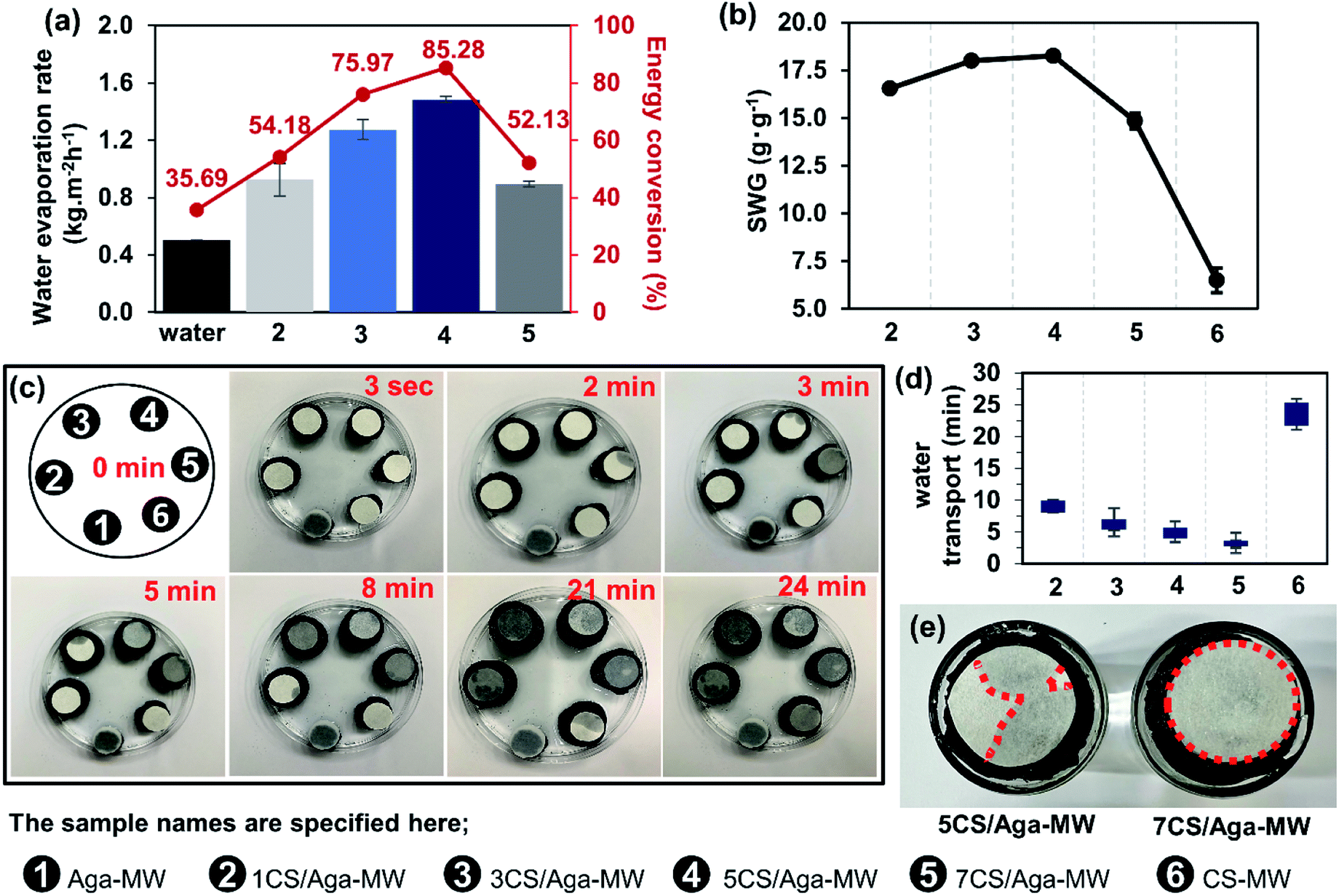 | ||
| Fig. 3 (a) The water evaporation efficiency related to energy conversion efficiency, (b) the saturated water content per unit gram (SWG) of the composited sponge evaporators, (c) photographs of water transport, (d) illustrated diagram representing the time period when the samples started to become wet, and (e) photograph of the top surface wettability of 5 and 7CS/Aga-MW after the 1 h solar evaporation test. | ||
Another key factor that can affect the evaporation performance of the evaporators is water transport to the evaporation surface. As such, water absorptivity and diffusivity of each sample were studied. The absorbed water contents at equilibrium of 1, 3, 5, 7CS/Aga-MW are more than 93 wt%, and are presented in Fig. S6.† The saturated water content per unit gram (SWG) of 1, 3, 5, 7CS/Aga-MW and CS-MW (as the control) is 16.66, 18.00, 18.25, 14.84, and 6.49 g g−1, respectively (Fig. 3b). Coincidentally, the highest water content belongs to 5CS/Aga-MW, which also corresponds to the best performing evaporator in terms of the evaporation rate. While the SWG increases as a result of increasing CS content from a CS to aga ratio of 1:1 to 5:1, it was dramatically reduced for 7CS/Aga-MW (CS:Aga = 7:1) and CS-MW. The drastic reduction in the SWG could be due to the formation of large, water impenetrable CS crystals, as discussed previously.
The morphology and microstructure are key factors affecting water transport from the reservoir to the evaporating surface. Snapshots at various time intervals at which the cellulose paper on top of each sample turning wet were taken and are shown in Fig. 3c. The rate of water diffusivity follows this order: Aga-MW > 7CS/Aga-MW > 5CS/Aga-MW > 3CS/Aga-MW > 1CS/Aga-MW > CS-MW (Fig. 3d). The evaporation rate and efficiency of 7CS/Aga-MW was lower than expected despite having the most rapid water transport mechanism. Several factors could have contributed to this phenomenon. Therefore, optimal water supply should be pursued to achieve the best energy matching.65 According to the energy mismatch concept, the surface water on the top of the evaporators was observed. When a fibrous cellulose paper was immediately placed on the top surface of the evaporator after the solar evaporation test, it turned fully wet immediately for 7CS/Aga-MW, indicating very rapid water transport, likely due to the more vertically aligned channels (Fig. 3e). Therefore, the anisotropic porous structure in 7CS/Aga-MW brought about rapid water diffusivity leading to more energy loss compared to 5CS/Aga-MW (Table S1†).
Improvement of the water evaporation rate due to the 3D structure with an increased height
Increasing the height of 5CS/Aga-MW above the reservoir surface would enhance water evaporation since the exposed surface area of the material could gain energy from the surrounding environment to boost the water evaporation rate. To accurately measure the water evaporation rate, the spotting size of incident light was controlled to be identical to the surface area at the top of the evaporator. An IR thermal camera was used to capture the temperature activity for 5CS/Aga-MW during the solar evaporation process, as presented in Fig. 4a. The evaporation rate with various exposed heights calculated based on mass change under one sun irradiation is present in Fig. 4b. Indeed, an increased evaporator height results in a higher steady-state water evaporation rate, which is 2.24 and 3.07 kg m−2 h−1 for 30 and 60 mm height, respectively (Fig. 4c).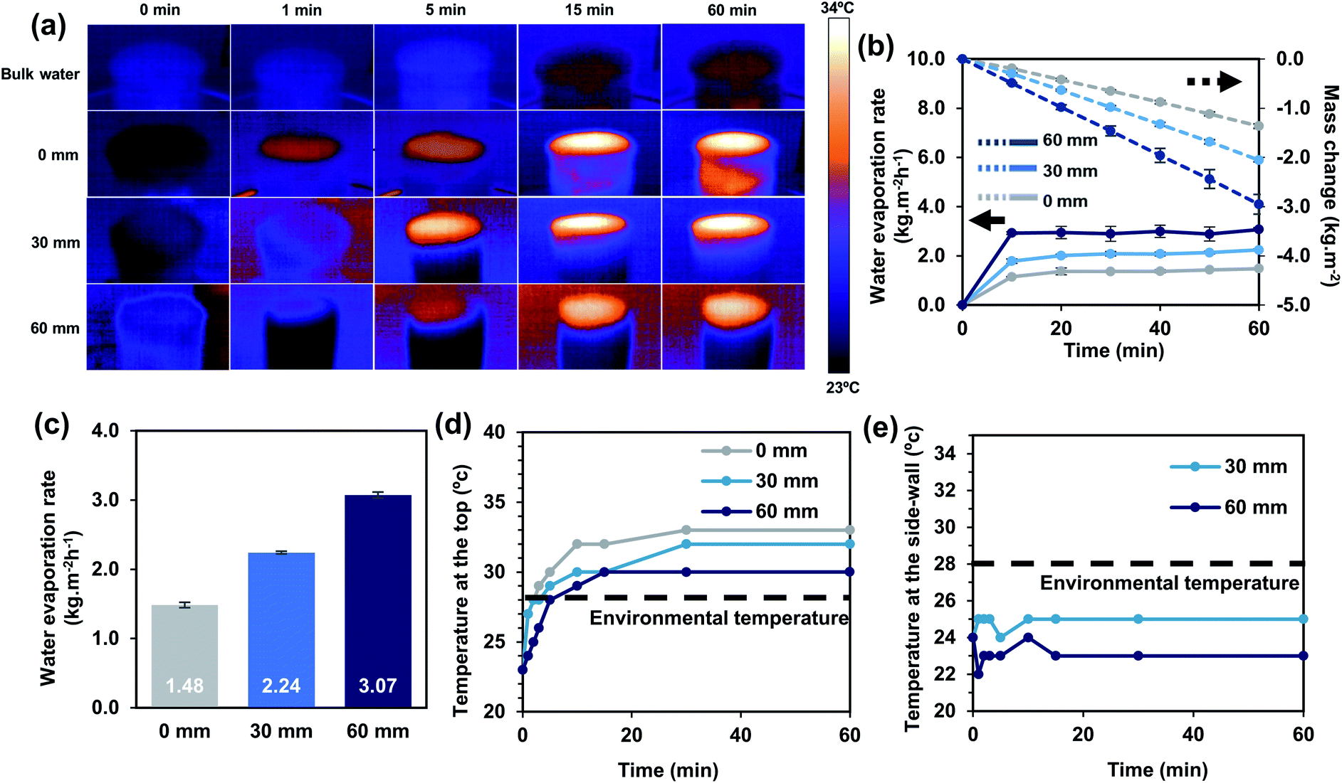 | ||
| Fig. 4 (a) IR thermal images for 5CS/Aga-MW at different heights and bulk water during 1 h solar evaporation under one sun irradiation, (b) the water evaporation rate and mass change due to 5CS/Aga-MW at different heights per unit time, (c) the water evaporation rate due to 5CS/Aga-MW at different heights, (d) the temperature change at the top surface of 5CS/Aga at different heights and (e) the temperature change at the side surface of 5CS/Aga at different heights. | ||
As a result, it was observed that the increased exposed surface area leads to a lower average temperature at the top surface. The top surface temperature of the 0 mm photothermal sponge during solar evaporation under one sun irradiation was 33 °C. However, when the height was increased to 30 and 60 mm, the temperature at the top surface decreased to 32 and 30 °C, respectively (Fig. 4d). This possibly led to lesser energy loss at the top evaporative surface due to smaller temperature differences with the surroundings. On the other hand, the side surface has a lower temperature than its environmental temperature, due to the absence of light irradiance and constant evaporation taking place (Fig. 4e). Moreover, the temperature in the water reservoir decreased with increasing evaporator height (Fig. S7a†), indicating lesser conduction and possibly some convection heat loss. This would allow additional convection and radiation heat gain from the environment to the system as illustrated in Fig. S7b.†
The relation between the evaporator height and energy exchange is best illustrated using the energy conservative rule, which includes the solar energy input, vapor output, heat capacity of water, and heat exchange with the environment, in the form of either energy gain or loss, as shown in Fig. S7c, and eqn (8) and (9) in the ESI.† At 0 mm-height of the 5CS/Aga-MW sponge, the energy utilization for evaporation is only 1.2350 W, whereas those of the 30 and 60 mm height are 1.4723 and 1.8451 W, respectively, due to contribution from environmental heat radiation and convection. In typical, only solar energy with reflection loss is taken into account to drive water evaporation for 2D evaporators. Thus, we assume that 100% energy utilization would be 1.4700 W given our 2D projection area of irradiation. This would correspond to energy utilizations of 84.01, 100.16, and 125.51% for 0, 30 and 60 mm height. The calculation of energy utilization is shown in the ESI.† The increase in height results in significant improvement in the evaporation rate, beyond the theoretical limit of a conventional 2D solar evaporator. Nevertheless, there is an issue in anti-salt-fouling during the solar desalination process when the height was increased to 60 mm. For this reason, the height of 5CS/Aga-MW is limited to provide a good water evaporation rate with long-term use under salt desalination. This issue will be discussed more in the subsequent section.
Solar desalination and the self-regeneration test
Anti-salt-fouling properties are crucial for stable water production without the need for human intervention. The evaporation performance of 3D – 5CS/Aga-MW with 60 mm and 30 mm above a saltwater reservoir of 3.5% salinity was studied. The experiment was done by running the test under one sun irradiation for 8 hours and a dark environment for 16 h for 10 consecutive days. The performance of the 60 mm evaporator shows a superior evaporation rate which is maintained at approximately 3.04 kg m−2 h−1 for the first 2 days as shown in Fig. 5a. Similarly, the evaporation test was also carried out with 30 mm-5CS/Aga-MW. Impressively, the stable evaporation rate was recorded to be ∼2.19 kg m−2 h−1 throughout the 10 day experiment as shown in Fig. 5b, which was similar to its evaporation performance in pure water. The water evaporation rate of the 60 mm evaporator was lowered because of salt precipitation at the surface evaporator. (Fig. S8a and b†) and possibly at the evaporator ducts. The poor self-cleaning property could be assumed to be due to the long water pathway from the reservoir to the top surface of the evaporator, resulting in poor advection-diffusion of ions inside the evaporator. In contrast, no salt crystallization can be observed on the surface of the 30 mm evaporator even after ten days (Fig. 5c). | ||
| Fig. 5 Water evaporation performance for the long-term evaporation rate of the evaporator in 3.5% w/v. NaCl under one sun irradiation, using (a) 60 mm-5CS/Aga-MW for 5 days and (b) 30 mm-5CS/Aga-MW for 10 days, (c) salt crystallization observation for cycles 1, 5 and 10, simulated salt regeneration test of the (d) 5CS/Aga and (e) 1CS/Aga sponge evaporator, (f) schematic of water diffusion for low and high tortuosity structures, (g) water evaporation rate and mass change in the NaCl solution at 3.5, 10 and 20 wt%, using 5CS/Aga-MW with 30 mm height and (h) the 4 main ions in seawater before and after desalination. | ||
On the other hand, while maintaining the same height, the effect of the pore structure on anti-salt-fouling ability was investigated. A self-regeneration test for 5CS/Aga-MW and 1CS/Aga-MW with a height of 30 mm was conducted. As shown in Fig. 5d, there was no salt found at the top of the evaporator surface for 5CS/Aga-MW after 6 h. On the other hand, 1CS/Aga-MW shows salt residue at the top of the evaporator after 6 h (Fig. 5e). This confirms that 5CS/Aga-MW has better anti-salt-fouling or self-regeneration properties than 1CS/Aga-MW, most probably due to the low tortuosity of the 5CS/Aga-MW pore structure. In contrast, the high tortuosity of 1CS/Aga-MW slowed down water transport, and the salt concentration cannot be easily redistributed in this structure. More importantly, this shows that the mixed pore structure not only allows a high water evaporation rate with good water transport, but the salt concentration gradient can also be easily balanced, simultaneously. For a better understanding of water transport, the video still for the water transport test of the 30 mm – 1CS/Aga and 5CS/Aga sponge (without MWCNTs), using methylene blue solution to monitor vertical transport is presented in Fig S9a and b.† The vertical transport of methylene blue in the 5CS/Aga sponge was faster than that in 1CS/Aga. Within 25 min, methylene blue can be transported to the top of the 5Cs/Aga sponge while 2/3 of the height of the 1CS/Aga sponge was filled with methylene blue. The schematic diagram in Fig. 5f illustrates the water transport mechanisms in the different pore structures. Due to the low tortuosity of 5CS/Aga-MW, advection and diffusion occurred easily, leading to salt exchange between the vertical and horizontal pore channels.25,38,66 At the same time, an efficient water evaporation rate and self-regeneration property could be achieved.
A highly stable evaporator can be demonstrated in terms of the salt-resistant evaporation test. Interestingly, 5CS/Aga-MW with 30 mm height shows a stable evaporation rate with efficiency between 1.96 and 2.19 kg m−2 h−1 for different salinities (3.5, 10, and 20 wt% of NaCl) (Fig. 5g). Even though salt precipitation was found on the top surface of the evaporator for 20% salinity due to the extremely high salt concentration (Fig. S10a†), it recovered after being left for 12 hours at ambient temperature (Fig. S10b†). To investigate the water quality after desalination using 5CS/Aga-MW, a solar desalination system prototype was fabricated to collect purified water. The experiment was conducted using actual seawater from West Coast beach, Singapore. The concentration of four kinds of ions (Na+, K+, Ca2+, and Mg2+) was selected for evaluation. After the desalination process, the concentrations of each ion were reduced by about 3 to 4 orders of magnitude, achieving a level way below the necessary concentration required in drinking water as defined by the World Health Organization (WHO) (Fig. 5h). As compared to other 3D solar evaporators, not many 3D evaporators could reach such a high evaporation rate and yet maintain a suitable salt concentration gradient for self-regeneration to take place (Table S2†).
Conclusions
In conclusion, 3D-structured sponge evaporators fabricated using natural polymers embedded with multi-walled carbon nanotubes are presented. The physical structure, and most importantly, the pore structure of the evaporators can be tailored through the manipulation of the chemical composition, in particular, the CS to Aga ratio. The mixed pore structure of 5CS/Aga-MW shows the best evaporation performance, having steady-state evaporation rates of 2.24 and 3.07 kg m−2 h−1 for 30 mm and 60 mm above the water level. Such an impressive performance would correspond to an energy utilization of 100.16% and 125.51%, exceeded the theoratical limit of conventional 2D evaporators, which was achieved through harvesting additional energy from the surrounding environment. Furthermore, 60 mm and 30 mm-5CS/Aga-MW maintain an evaporation rate of 3.04 and 2.19 kg m−2 h−1, for 2 and 10 days, respectively, using saline water with 3.5% salinity, which has rarely been reported for monolithic 3D-structured solar evaporators with anti-salt-fouling properties. The excellent performance of 5CS/Aga-MW was attributed largely to its mixed pore structure that has low tortuosity, thereby providing sufficient water supply together with the ability to balance out the salt concentration gradient rather quickly. Such a bottom-up approach in utilizing bio-based materials to fabricate solar evaporators with controllable pore structures could be a valuable pathway to fabricate 3D-structured evaporators with good performance in terms of both the evaporation rate and anti-salt-fouling ability, utilizing sustainable resources with sustainable materials for sustainable life.Author contributions
P. A.: conceptualization, experimental design, sample preparation, characterization, data analysis, formal manuscript writing/revision; J. J. K.: conceptualization, experimental design, manuscript revision; J. C. C. Y.: characterization, data analysis, manuscript revision; S. L.: characterization, data analysis, manuscript revision; X. H.: data analysis, manuscript revision; N. L.: characterization, manuscript revision; C. H.: conceptualization, funding acquisition, project supervision, manuscript revision. The manuscript was written through the contributions of all authors. All authors have given approval to the final version of the manuscript.Conflicts of interest
There are no conflicts to declare.Acknowledgements
P. A. gratefully acknowledges the National Nanotechnology Center (NANOTEC-NSTDA) and Royal Thai Government scholarship (OCSC), Thailand for fully funding the PhD scholarship. This work was partially supported by A*STAR IMRE – SCG Chemicals Advanced Composite Joint Lab (IAF-ICP Project No: I1801E0024). The authors are thankful to Mr. Pinyawee Songkhum for informative graphic work.References
- A. Boretti and L. Rosa, npj Clean Water, 2019, 2, 15 CrossRef.
- M. M. Mekonnen and A. Y. Hoekstra, Sci. Adv., 2016, 2, e1500323 CrossRef PubMed.
- E. Mathioulakis, V. Belessiotis and E. Delyannis, Desalination, 2007, 203, 346–365 CrossRef CAS.
- Y.-S. Jun, X. Wu, D. Ghim, Q. Jiang, S. Cao and S. Singamaneni, Acc. Chem. Res., 2019, 52, 1215–1225 CrossRef CAS PubMed.
- F. E. Ahmed, R. Hashaikeh and N. Hilal, Desalination, 2019, 453, 54–76 CrossRef CAS.
- Q. Jiang, L. Tian, K.-K. Liu, S. Tadepalli, R. Raliya, P. Biswas, R. R. Naik and S. Singamaneni, Adv. Mater., 2016, 28, 9400–9407 CrossRef CAS PubMed.
- K.-K. Liu, Q. Jiang, S. Tadepalli, R. Raliya, P. Biswas, R. R. Naik and S. Singamaneni, ACS Appl. Mater. Interfaces, 2017, 9, 7675–7681 CrossRef CAS PubMed.
- H. Gholami Derami, Q. Jiang, D. Ghim, S. Cao, Y. J. Chandar, J. J. Morrissey, Y.-S. Jun and S. Singamaneni, ACS Appl. Nano Mater., 2019, 2, 1092–1101 CrossRef CAS.
- S. Cao, X. Wu, Y. Zhu, P. Gupta, A. Martinez, Y. Zhang, D. Ghim, Y. Wang, L. Liu, Y.-S. Jun and S. Singamaneni, J. Mater. Chem. A, 2021, 9, 22585–22596 RSC.
- M. Gao, L. Zhu, C. K. Peh and G. W. Ho, Energy Environ. Sci., 2019, 12, 841–864 RSC.
- L. Zhu, M. Gao, C. K. N. Peh and G. W. Ho, Mater. Horiz., 2018, 5, 323–343 RSC.
- L. Zhu, M. Gao, C. K. N. Peh and G. W. Ho, Nano Energy, 2019, 57, 507–518 CrossRef CAS.
- P. Tao, Nat. Energy, 2018, 3, 1031–1041 CrossRef.
- J. Zhou, Y. Gu, P. Liu, P. Wang, L. Miao, J. Liu, A. Wei, X. Mu, J. Li and J. Zhu, Adv. Funct. Mater., 2019, 29, 1903255 CrossRef CAS.
- K. Wang, B. Huo, F. Liu, Y. Zheng, M. Zhang, L. Cui and J. Liu, Desalination, 2020, 481, 114303 CrossRef CAS.
- Y. Zhang and S. C. Tan, Nat. Sustain., 2022 DOI:10.1038/s41893-022-00880-1.
- H. Ghasemi, G. Ni, A. M. Marconnet, J. Loomis, S. Yerci, N. Miljkovic and G. Chen, Nat. Commun., 2014, 5, 4449 CrossRef CAS PubMed.
- X. Hu, W. Xu, L. Zhou, Y. Tan, Y. Wang, S. Zhu and J. Zhu, Adv. Mater., 2017, 29, 1604031 CrossRef PubMed.
- J. Jia, W. Liang, H. Sun, Z. Zhu, C. Wang and A. Li, Chem. Eng. J., 2019, 361, 999–1006 CrossRef CAS.
- R. Li, L. Zhang, L. Shi and P. Wang, ACS Nano, 2017, 11, 3752–3759 CrossRef CAS PubMed.
- S. Cao, X. Wu, Y. Zhu, R. Gupta, A. Tan, Z. Wang, Y.-S. Jun and S. Singamaneni, J. Mater. Chem. A, 2020, 8, 5147–5156 RSC.
- H. Wang, A. Du, X. Ji, C. Zhang, B. Zhou, Z. Zhang and J. Shen, ACS Appl. Mater. Interfaces, 2019, 11, 42057–42065 CrossRef CAS PubMed.
- Z. Sun, Z. Li, W. Li and F. Bian, Cellulose, 2020, 27, 481–491 CrossRef CAS.
- Y. Zou, X. Chen, W. Guo, X. Liu and Y. Li, ACS Appl. Energy Mater., 2020, 3, 2634–2642 CrossRef CAS.
- J. J. Koh, G. J. H. Lim, S. Chakraborty, Y. Zhang, S. Liu, X. Zhang, S. C. Tan, Z. Lyu, J. Ding and C. He, Nano Energy, 2021, 79, 105436 CrossRef CAS.
- Y. Shi, R. Li, Y. Jin, S. Zhuo, L. Shi, J. Chang, S. Hong, K.-C. Ng and P. Wang, Joule, 2018, 2, 1171–1186 CrossRef CAS.
- W. Tu, Z. Wang, Q. Wu, H. Huang, Y. Liu, M. Shao, B. Yao and Z. Kang, J. Mater. Chem. A, 2020, 8, 10260–10268 RSC.
- B. Shao, Y. Wang, X. Wu, Y. Lu, X. Yang, G. Y. Chen, G. Owens and H. Xu, J. Mater. Chem. A, 2020, 8, 11665–11673 RSC.
- D. P. Storer, J. L. Phelps, X. Wu, G. Owens, N. I. Khan and H. Xu, ACS Appl. Mater. Interfaces, 2020, 12, 15279–15287 CrossRef CAS PubMed.
- T. Gao, X. Wu, Y. Wang, G. Owens and H. Xu, Sol. RRL, 2021, 5, 2100053 CrossRef CAS.
- Y. Wang, X. Wu, T. Gao, Y. Lu, X. Yang, G. Y. Chen, G. Owens and H. Xu, Nano Energy, 2021, 79, 105477 CrossRef CAS.
- K. Wang, Z. Cheng, P. Li, Y. Zheng, Z. Liu, L. Cui, J. Xu and J. Liu, J. Colloid Interface Sci., 2021, 581, 504–513 CrossRef CAS PubMed.
- P. Sun, W. Zhang, I. Zada, Y. Zhang, J. Gu, Q. Liu, H. Su, D. Pantelić, B. Jelenković and D. Zhang, ACS Appl. Mater. Interfaces, 2020, 12, 2171–2179 CrossRef CAS PubMed.
- N. Xu, X. Hu, W. Xu, X. Li, L. Zhou, S. Zhu and J. Zhu, Adv. Mater., 2017, 29, 1606762 CrossRef PubMed.
- Z. Sun, W. Li, W. Song, L. Zhang and Z. Wang, J. Mater. Chem. A, 2020, 8, 349–357 RSC.
- Y. Wang, X. Wu, P. Wu, J. Zhao, X. Yang, G. Owens and H. Xu, Sci. Bull., 2021, 66, 2479–2488 CrossRef CAS.
- Y. Xu, X. Xiao, X. Fan, Y. Yang, C. Song, Y. Fan and Y. Liu, J. Mater. Chem. A, 2020, 8, 24108–24116 RSC.
- Y. Kuang, C. Chen, S. He, E. M. Hitz, Y. Wang, W. Gan, R. Mi and L. Hu, Adv. Mater., 2019, 31, 1900498 CrossRef PubMed.
- L. Li, N. He, B. Jiang, K. Yu, Q. Zhang, H. Zhang, D. Tang and Y. Song, Adv. Funct. Mater., 2021, 31, 2104380 CrossRef CAS.
- Y. Xia, Q. Hou, H. Jubaer, Y. Li, Y. Kang, S. Yuan, H. Liu, M. W. Woo, L. Zhang, L. Gao, H. Wang and X. Zhang, Energy Environ. Sci., 2019, 12, 1840–1847 RSC.
- H.-Y. Zhao, J. Huang, J. Zhou, L.-F. Chen, C. Wang, Y. Bai, J. Zhou, Y. Deng, W.-X. Dong, Y.-S. Li and S.-H. Yu, ACS Nano, 2022, 16, 3554–3562 CrossRef CAS PubMed.
- Y. Peng, X. Zhao and C. Liu, J. Mater. Chem. A, 2021, 9, 22472–22480 RSC.
- Y. Xu, J. Xu, J. Zhang, X. Li, B. Fu, C. Song, W. Shang, P. Tao and T. Deng, Nano Energy, 2022, 93, 106882 CrossRef CAS.
- L. Zhu, L. Sun, H. Zhang, H. Aslan, Y. Sun, Y. Huang, F. Rosei and M. Yu, Energy Environ. Sci., 2021, 14, 2451–2459 RSC.
- J. P. Chaudhary, S. K. Nataraj, A. Gogda and R. Meena, Green Chem., 2014, 16, 4552–4558 RSC.
- Q. Cao, Y. Zhang, W. Chen, X. Meng and B. Liu, Int. J. Biol. Macromol., 2018, 106, 1307–1313 CrossRef CAS PubMed.
- R. M. Felfel, M. J. Gideon-Adeniyi, K. M. Zakir Hossain, G. A. F. Roberts and D. M. Grant, Carbohydr. Polym., 2019, 204, 59–67 CrossRef CAS PubMed.
- S. Saeedi Garakani, M. Khanmohammadi, Z. Atoufi, S. K. Kamrava, M. Setayeshmehr, R. Alizadeh, F. Faghihi, Z. Bagher, S. M. Davachi and A. Abbaspourrad, Int. J. Biol. Macromol., 2020, 143, 533–545 CrossRef CAS PubMed.
- F. Yokoyama, E. C. Achife, J. Momoda, K. Shimamura and K. Monobe, Colloid Polym. Sci., 1990, 268, 552–558 CrossRef CAS.
- X. Wu, Y. Liu, X. Li, P. Wen, Y. Zhang, Y. Long, X. Wang, Y. Guo, F. Xing and J. Gao, Acta Biomater., 2010, 6, 1167–1177 CrossRef CAS PubMed.
- S. Deville, J. Mater. Res., 2013, 28, 2202–2219 CrossRef CAS.
- J. Nie, Z. Wang and Q. Hu, Sci. Rep., 2016, 6, 36053 CrossRef CAS PubMed.
- J. Han, C. Zhou, Y. Wu, F. Liu and Q. Wu, Biomacromolecules, 2013, 14, 1529–1540 CrossRef CAS PubMed.
- M. Chau, K. J. De France, B. Kopera, V. R. Machado, S. Rosenfeldt, L. Reyes, K. J. W. Chan, S. Förster, E. D. Cranston, T. Hoare and E. Kumacheva, Chem. Mater., 2016, 28, 3406–3415 CrossRef CAS.
- I. P. Khosalim, Y. Y. Zhang, C. K. Y. Yiu and H. M. Wong, Sci. Rep., 2022, 12, 1971 CrossRef CAS PubMed.
- J. P. Chaudhary, N. Vadodariya, S. K. Nataraj and R. Meena, ACS Appl. Mater. Interfaces, 2015, 7, 24957–24962 CrossRef CAS PubMed.
- X. Li, G. Ni, T. Cooper, N. Xu, J. Li, L. Zhou, X. Hu, B. Zhu, P. Yao and J. Zhu, Joule, 2019, 3, 1798–1803 CrossRef.
- C. Chen, Y. Kuang and L. Hu, Joule, 2019, 3, 683–718 CrossRef CAS.
- X. Li, J. Li, J. Lu, N. Xu, C. Chen, X. Min, B. Zhu, H. Li, L. Zhou, S. Zhu, T. Zhang and J. Zhu, Joule, 2018, 2, 1331–1338 CrossRef CAS.
- H. Li, Y. He, Z. Liu, B. Jiang and Y. Huang, Energy, 2017, 139, 210–219 CrossRef CAS.
- F. Ni, P. Xiao, C. Zhang, Y. Liang, J. Gu, L. Zhang and T. Chen, ACS Appl. Mater. Interfaces, 2019, 11, 15498–15506 CrossRef CAS PubMed.
- Z. Zhu, Y. Xu, Y. Luo, W. Wang and X. Chen, J. Mater. Chem. A, 2021, 9, 702–726 RSC.
- H. Li, Z. Yan, Y. Li and W. Hong, Water Res., 2020, 177, 115770 CrossRef CAS PubMed.
- W. Zhang, G. Zhang, Q. Ji, H. Liu, R. Liu and J. Qu, ACS Appl. Mater. Interfaces, 2019, 11, 9974–9983 CrossRef CAS PubMed.
- X. Mu, Y. Gu, P. Wang, J. Shi, A. Wei, Y. Tian, J. Zhou, Y. Chen, J. Zhang, Z. Sun, J. Liu, B. Peng and L. Miao, Sol. RRL, 2020, 4, 2000341 CrossRef.
- S. He, C. Chen, Y. Kuang, R. Mi, Y. Liu, Y. Pei, W. Kong, W. Gan, H. Xie, E. Hitz, C. Jia, X. Chen, A. Gong, J. Liao, J. Li, Z. J. Ren, B. Yang, S. Das and L. Hu, Energy Environ. Sci., 2019, 12, 1558–1567 RSC.
Footnote |
| † Electronic supplementary information (ESI) available. See https://doi.org/10.1039/d2ta03452b |
| This journal is © The Royal Society of Chemistry 2022 |