
 Open Access Article
 This Open Access Article is licensed under a
 Creative Commons Attribution 3.0 Unported Licence
Anion exchange membrane water electrolysis using Aemion™ membranes and nickel electrodes†
Amirreza
Khataee
 *a,
Anuja
Shirole
b,
Patric
Jannasch
b,
Andries
Krüger
a and
Ann
Cornell
a
*a,
Anuja
Shirole
b,
Patric
Jannasch
b,
Andries
Krüger
a and
Ann
Cornell
a
aDivision of Applied Electrochemistry, Department of Chemical Engineering, KTH Royal Institute of Technology, SE-100 44 Stockholm, Sweden. E-mail: khat@kth.se
bDepartment of Chemistry, Lund University, P. O. Box 124, SE-221 00 Lund, Sweden
First published on 5th July 2022
Abstract
Anion exchange membrane water electrolysis (AEMWE) is a potentially low-cost and sustainable technology for hydrogen production that combines the advantages of proton exchange membrane water electrolysis and traditional alkaline water electrolysis systems. Despite considerable research efforts in recent years, the medium-term (100 h) stability of Aemion™ membranes needs further investigation. This work explores the chemical and electrochemical durability (>100 h) of Aemion™ anion exchange membranes in a flow cell using nickel felt as the electrode material on the anode and cathode sides. Remixing the electrolytes between the AEMWE galvanostatic tests was very important to enhance electrolyte refreshment and the voltage stability of the system. The membranes were analyzed by NMR spectroscopy after the AEMWE tests, and the results showed no sign of severe chemical degradation. In a separate experiment, the chemical stability and mechanical integrity of the membranes were studied by soaking them in a strongly alkaline electrolyte for a month (>700 h) at 90 °C, followed by NMR analysis. A certain extent of ionic loss was observed due to chemical degradation and the membranes disintegrated into small pieces.
Introduction
Global warming and climate change give rise to the utilization of clean and renewable energies. Water electrolysis is one of the promising technologies that can be used to exploit renewable energies (solar and wind) to produce hydrogen for a sustainable future.1,2 Hydrogen gas is an efficient energy carrier and an alternative to fossil fuels to generate power.3 It can be produced from various sources such as water,1–3 and the extremely high gravimetric energy density of hydrogen is another attractive property. Today, hydrogen has a production rate of 500 billion m3 year−1 and is used in application areas like fertilizers, petrochemical processes, fuel cells, steel refining, etc.4,5 Currently, less than 4% of hydrogen is produced by electrolysis processes, mainly due to the high production costs.1,2 The most mature and commercially available electrolysis technology, alkaline water electrolysis (AWE), benefits from using inexpensive non-noble electrode materials (e.g., nickel and steel).2,6 Although AWE has a track record spanning over 100 years in the industry, it suffers from the highly corrosive electrolyte (20–30% KOH). Additionally, the operational capacity of AWE systems is limited by the applied current densities. To avoid gas crossover and safety issues2,6 at low current densities, AWE is usually operated at high current densities, which imposes high overpotential in the system due to the high resistance of the diaphragm.Proton exchange membrane water electrolysis (PEMWE) was introduced in the late 1960s and could overcome some of the disadvantages of the AWE technology.7 The main advantages of the PEMWE technology are high efficiency, compact design, and high operating current densities (2 A cm−2 at 2.1 V).6,8 Also, PEMWE benefits from membrane separation and pure water feed. The benchmark cation exchange membrane, Nafion, is the standard separator used for PEMWE systems. Nafion reduces the gas crossover significantly compared to the diaphragm used in AWE and provides high conductivity due to the high mobility of exchanged protons.
On the other hand, the harsh acidic environment of PEMWE limits the material choice for the catalyst, membrane, current collector, and bipolar plate. Furthermore, the high cost of Nafion and catalysts used on the cathode (Pt) and anode (IrO2) sides is another drawback of PEMWE.1,6,8,9
Anion exchange membrane water electrolysis (AEMWE) is an emerging technology that has demonstrated superior features and seems to be an excellent solution to the drawbacks mentioned above. AEMWE incorporates the advantages of AWE (low-cost and abundant materials) and PEMWE (moderate temperature, membrane separation, and pure water). While keeping the alkaline environment to reduce the electrocatalyst cost as in AWE, the current is carried by hydroxide ions through a dense polymeric anion exchange membrane (AEM).6,8 In addition, to reduce the corrosion issues (20–30% KOH) of AWE, the most common electrolytes that have been used in AEMWE systems are moderately concentrated KOH, and a mixture of K2CO3 and KHCO3.6,10,11
Recent reports on the concept of AEMWE show improved performance using optimal operational conditions.6,11–15 However, the main challenges with the low ion conductivity and long-term (electro)chemical stability of the AEMs (under highly basic conditions at elevated temperatures) remain. In general, the long-term use of AEMs is limited by the stability of the polymeric backbone and pendant cationic functional groups. Different benzimidazolium and imidazolium cations are widely employed at high pH.16–19 Still, four distinct degradation pathways have been identified for these aromatic heterocyclic cations in alkaline media: (I) nucleophilic substitution (SN2) of the methyl groups at the N1 and N3 atoms, (II) nucleophilic addition–elimination at the C4, C5 and C2 atoms, (III) ylide pathway at the N1 and (or) N3 methyl hydrogen atoms, and (IV) ylidene pathway at the H4, H5 and H2 atoms.20 However, the most common degradation pathway has been reported to be the nucleophilic addition–elimination at the C2 position, mainly because the C2 position is more electropositive compared to other positions. This makes it susceptible to hydroxide (OH−) ion attack, consequently leading to the ring-opening.16,20
Different strategies have been proposed to protect the C2 atom against nucleophilic attack. Substitution at the C2 position by bulky groups such as mesitylene is an effective method to hinder hydroxide ion attack. Replacing the methyl groups of mesitylene by bulky phenyl groups further increases the steric hindrance at the C2 position.19,21,22 The bulky groups create a considerable barrier against nucleophilic attack, while the electron donating effect of these groups makes the C2 position less susceptible to these attacks. Substituting the C4 and C5 positions of imidazolium with methyl groups also increases the stability by avoiding degradation pathway IV.16,20
Using the strategies mentioned above, imidazolium-based AEMs with ether-free polyaryl backbones have shown promising chemical, thermal and mechanical stabilities under non-flowing conditions and in flow cell applications. For example, Holdcroft et al. reported excellent alkaline stability after immersion in 10 M KOH at 80 °C after 240 h.19 Also, only 5% degradation was reported by Wang et al. for a polybenzimidazole-based AEM with a steric hindrance backbone after 800 h of immersion in 1 M NaOH at 60 °C.21 The alkaline stability increased significantly after replacing the phenyl group with mesitylene or hexamethyl-p-terphenylene groups.16,23–25 The latter group has been used to fabricate commercially available imidazolium-based AEMs named Aemion™. These membranes reach high hydroxide conductivity (40–140 mS cm−1) and ion exchange capacity (1.4–2.5 meq. g−1). In addition, they have shown sufficient chemical stability in water electrolysis for around 16 h, with a relatively low degradation rate at 50 °C in 0.1 M KOH electrolyte.26 Pushkareva et al. reported no severe degradation for Aemion AEMs (60 °C, 1 M KOH) based on the polarization curves.11 Recently, Fortin et al.26 have investigated the electrochemical performance and short-term (13 h) stability of Aemion™ AEMs in AEMWE systems using catalyst-coated electrodes. The results are promising but the medium- and long-term stability of Aemion™ AEMs are still unknown from this study. Therefore, the current research investigates the long-term and medium-term alkaline stability of Aemion™ AEMs under non-flowing conditions (700 h) and flow cell applications (100 h), respectively. Also, to exclude the catalyst effect on the membrane performance, nickel felt electrodes were used on both sides of AEMWE.
Experimental
Chemicals and materials
All chemicals were commercially available and used without further purification. Potassium hydroxide (KOH, 85%, VWR) was used as the electrolyte for the AEMWE system and pretreatment of AEMs. High purity potassium hydroxide (99.99%) was supplied from Sigma-Aldrich and was used to study effects of the purity of the electrolyte on the AEMWE performance. Commercial nickel felt (75% porous, BEKAERT) was used as the cathode and as the anode. AEMION™ AEMs with different specifications and in iodide form were purchased from Ionomr, Canada. J-Flex Rubber Products provided the Viton sealing gaskets. For 1H NMR spectroscopy, dimethyl sulfoxide (DMSO, Sigma-Aldrich) and trifluoroacetic acid (TFA, Sigma-Aldrich) were used.Pretreatment of Aemion™ membranes and nickel felt
All AEMs were pretreated by submersion in 1 M KOH for, at least overnight before AEMWE tests. The AEMs were rinsed with Milli-Q water directly after this to remove the excess KOH from their surface. The nickel electrodes were pretreated by immersion in 4 M hydrochloric acid solution for 10 min at room temperature, and were then washed with Milli-Q water several times until a neutral pH was achieved. For comparison purposes, the nickel felt was pretreated thermally at 500 °C for three hours under an air atmosphere.Swelling ratio (%)
The swelling ratio was measured by immersing the AEMs (with an area of 5 cm2) into 1 M KOH at 60 °C for 48 h. The membranes were then taken out and wiped with tissue paper before quickly measuring their length (Lwet). Next, the AEMs were dried under vacuum for 48 h at 45 °C, and their length was measured (Ldry). The swelling ratio was calculated as follows: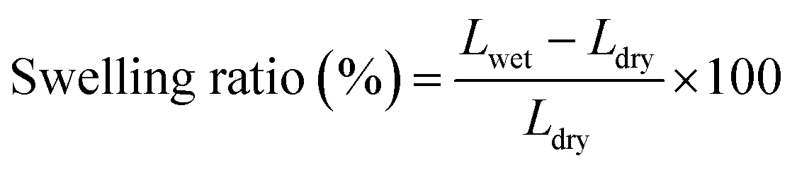 | (1) |
Cyclic voltammetry
Cyclic voltammograms were recorded at room temperature at a scan rate of 10 mV s−1 using a high power Iviuim XP10 potentiostat in a three-electrode electrochemical cell consisting of a 1 cm2 nickel felt working electrode, a platinum-mesh counter electrode and a Ag/AgCl reference electrode.Electrochemical characterization
AEMWE tests were conducted in an electrochemical cell (Fuel Cell Technologies) comprised of two nickel flow plates with a 5 cm2 serpentine flow field and two gold-plated copper current collectors. The flow field's channel width, depth, and landing width were 2 mm, 1.18 mm, and 1.6 mm, respectively. One piece of pretreated nickel felt (0.25 mm thickness) was placed on each nickel flow plate and separated using an anion exchange membrane. To avoid drying the AEMs, the cell was assembled quickly, and the circulation of electrolytes was initiated immediately. The cell was tightened using eight screws and by applying 7 N·m torque force. For sealing the cell, Viton gaskets with a thickness of 0.25 mm were used. The anolyte and catholyte tanks (250 mL) contained 1 M KOH. A two-channel peristaltic pump (Watson-Marlow) at 10 rpm, equivalent to 2 mL min−1, was used to circulate the electrolytes to the anode and cathode sides of the cell. All AEMWE tests were performed at 60 °C. The electrolytes were circulated through the cell for at least one hour until a temperature of 60 °C was achieved. During one hour of heating the setup, pre-testing was performed by monitoring the voltage at three or four different current densities (250 mA to 2 A, 10 s each) to check for short-circuiting. If the voltage was significantly lower than expected, then the system suffered from short-circuiting either externally (between current collectors and endplates) or internally (broken membrane).After pre-testing, electrochemical characterization was conducted according to the protocol shown in Fig. 1. All electrolysis tests, polarization curves and electrochemical impedance spectroscopy (EIS) spectra were collected using a ZAHNER ZENNIUM pro potentiostat. The stability test of the AEMWE system using different Aemion™ AEMs was carried out galvanostatically at 200 mA cm−2 for 20–22 h and was repeated four times. The characterization tests (polarization curves and EIS) were performed at the beginning and after each constant-current (CC) test. After the characterization test and before starting the next CC test, the setup was shut down and electrolytes on both sides were remixed. The lost electrolyte was compensated with a fresh 1 M KOH solution. Polarization data were measured by monitoring the cell voltage under galvanostatic conditions at different current densities starting from 5 mA cm−2 and 3 min per current density. The reported voltage values are averages of the last 30% readings on each current level. The voltage measurement at high current densities was terminated early if the voltage exceeded 2.4 V. The EIS measurements were performed under potentiostatic conditions at 2 V over a frequency range of 100 kHz to 1 Hz with a perturbation amplitude of 5 mV. All membranes were characterized by 1H NMR spectroscopy after AEMWE tests to check the (electro)chemical stability.
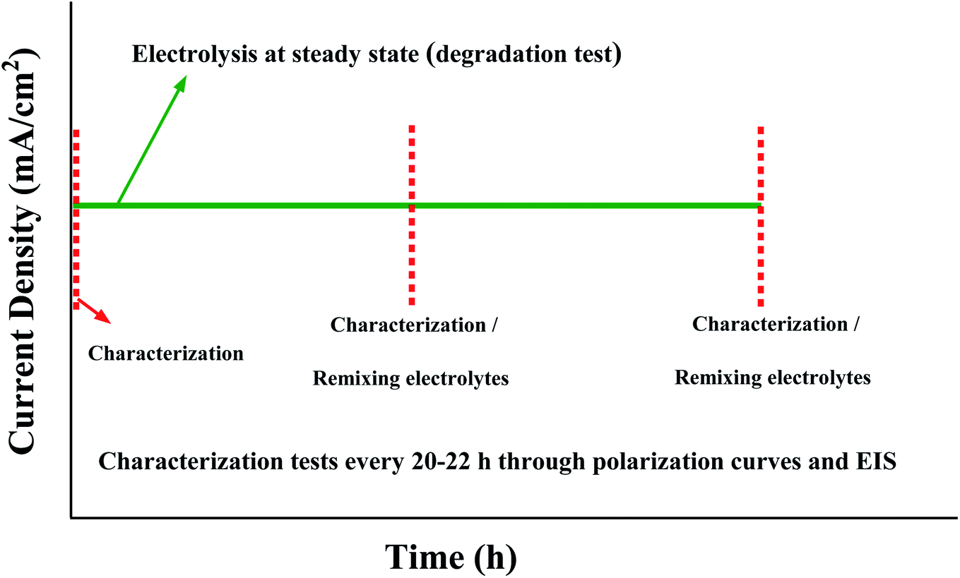 | ||
| Fig. 1 The protocol for characterization and stability tests of the AEMWE system. | ||
Electrochemical impedance spectroscopy (EIS) at different voltages
Potentiostatic EIS tests for AEMWE were conducted to separate and identify different resistances of the system using the same experimental setup as explained above. AF1-HNN8-50 was used as the AEM, and acid pretreated nickel felt as the electrode. EIS analysis was performed at different voltages starting from 1.8 V to 2.4 V with an increment rate of 100 mV. The frequency was varied in the range of 100 kHz to 1 Hz with a perturbation amplitude of 5 mV.Medium-term ex situ chemical stability of AEMs
The medium-term chemical stability and mechanical integrity of the AEMs in a strong alkaline environment were investigated by 1H NMR spectroscopy. The as-received AEM samples (AF1-HNN8-50 and AF1-HNN5-50) were treated with 1 M KOH solution at room temperature during 24 h for ion exchange to the OH− form. The samples were washed with distilled water for 1 h to remove the excess KOH, and then wiped off and transferred to 2 M KOH solution in test tubes. The sealed tubes containing AEM samples were stored in an oven at 90 °C for 1 month. After this, the samples were taken out and ion exchanged to the Br− form by immersion in 1 M NaBr solution for 48 h at room temperature. The samples were dried at room temperature for 24 h before being dissolved in DMSO-d6 for 1H NMR analysis. The 1H NMR spectra of the as-received AEMs (AF1-HNN8-50 and AF1-HNN5-50) were also recorded for reference. The extent of degradation (ionic loss) was estimated by calculating the percentage of the remaining cationic (benzimidazolium) groups from 1H NMR data using eqn (2): | (2) |
Results and discussion
Prior to testing the medium-term electrochemical performance of the AEMWE system, different resistances in the system were identified through EIS analysis. Also, the influence of pretreatment of the nickel electrodes on the total cell resistance was investigated. The following two paragraphs describe and discuss the results.EIS analysis of the AEMWE system at different voltages
Nyquist plots for the AEMWE system resulting from EIS analysis at varying cell voltages are presented in Fig. 2a. The first intercept of the plots with the real axis (Z′′ = 0) in the high-frequency region is interpreted as the pure ohmic resistance. It is the sum of the contributions from electron transport (i.e., current collectors, flow plates, and electrodes) and ion transport within the membrane and the electrolyte.27 Furthermore, there is a contact resistance between electrodes and the membrane. This is most likely due to the formation of nickel hydride and nickel (hydr)oxide layers during electrolysis on the cathode and anode sides, respectively.28–30 It should also be noted that the electrodes' surface conductivity is reduced due to the formation of the (hydr)oxide layer, which impedes electron transport.31 Due to the sufficient conductivity of the electrodes and electrolytes (1 M KOH), the electron and ion transport resistances would be negligible. As seen in the inset of Fig. 2a, a constant ohmic resistance, as expected, was achieved at different voltages. It is safe to assume that the ohmic resistance is dominated by the electrode-membrane contact resistance, electron transport in layers formed on electrodes, and ionic transport resistance within the membrane.27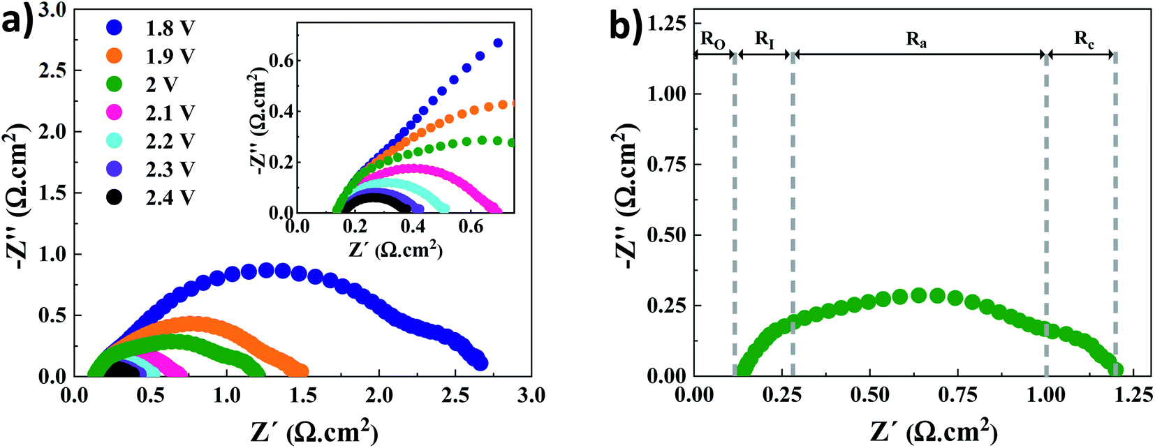 | ||
| Fig. 2 (a) EIS analysis at different voltages for the AEMWE system using an AF1-HNN8-50 AEM and acid pretreated nickel electrodes: inset is the zoomed figure; (b) different resistances represented in a Nyquist plot, exemplarily at 2 V. Abbreviations: O, I, a and c stand for ohmic, interface, anode and cathode, respectively. Experimental conditions: 1 M KOH electrolyte on each side, 10 rpm flow rate and operation at 60 °C. | ||
The low-frequency region is broken down into three semi-circles (Fig. 2b). The first semi-circle remains almost constant when varying the voltage associated with the electrode–electrolyte interface resistance (RI).30,32 Considering the charge transfer kinetics of electrochemical reactions, the anode side has a more sluggish rate as four electrons are needed for producing one molecule of oxygen while two electrons are required on the cathode side for producing one molecule of hydrogen. Therefore, the second and third semi-circles correspond to the charge transfer resistance at the anode (Ra) and cathode (Rc) sides, respectively. This is supported by the fact that when the voltage increases over 2 V the semi-circle that corresponds to the cathode side almost disappears. Finally, it should be mentioned that the mass transfer semicircle in the low-frequency region is disappearing due to electrolyte pumping and increased convection.
Pretreatment of nickel felt
Due to the hydrophobic nature of nickel felt, it is necessary to pretreat it for improving hydrophilicity and facilitating the mass-transport properties. Also, the passive (hydr)oxide layer that is naturally formed on the surface of nickel felt under an air atmosphere should be removed to expose metallic nickel as much as possible. To fulfill the goals mentioned above, hydrochloric acid (HCl) was used for pretreatment. Compared to other strong acids, HCl is the most commonly used acid in the literature as chloride ions substantially affect pitting formation on the metal surface.33,34 Pitting occurs in several stages,34 starting from the penetration of chloride ions through the passive film to the metal/oxide interface and formation of cationic vacancies due to the transfer of cations from the oxide layer to the electrolyte. Then, local thinning of the oxide layer, layer breaking, and finally local pit formation occurs. Nickel electrodes were thermally pretreated under an air atmosphere for comparison purposes. The performance of the AEMWE system when using acid and thermally pretreated together with untreated electrodes is shown in Fig. 3.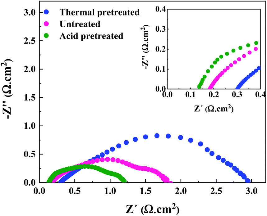 | ||
| Fig. 3 EIS analysis of the AEMWE system using electrodes with different pretreatment methods at 2 V. Experimental conditions: 1 M KOH electrolyte on each side, a HNN8-50 Aemion™ membrane, 10 rpm flow rate and operation at 60 °C. | ||
The AEMWE system using thermally pretreated electrodes possesses the most significant ohmic resistance as the oxide layer thickness is likely larger than the naturally-formed oxide layer, and both these have a thicker layer than acid pretreated electrodes.35 This is confirmed by the largest interface resistance (RI) for thermally pretreated electrodes.
The largest ohmic resistance is explainable as well. The oxide layer impedes electron transport and increases the contact resistance of the electrode membrane.
On the other hand, as mentioned earlier, the passive layer formation reduces the active sites on the electrode, which may explain why the charge transfer resistance at the anode side is the largest.
However, the AEMWE system using acid pretreated electrodes shows the lowest ohmic and charge transfer resistances due to the higher hydrophilicity, sufficient active sites, and enhanced mass transport. More precisely, high hydrophilicity helps to increase the interaction of electrolyte species with the electrode's surface for effective electron transport activity.
Effect of membrane failure and electrolyte purity on the electrochemical performance
A broken Aemion™ membrane (with a crack in the middle) was intentionally inserted in the cell and tested to get an idea of how the AEMWE performance would be with a broken membrane. As can be seen in Fig. S1,† extremely high current densities were achieved at very low voltages. In the same figure, the EIS analysis confirms the latter as quite a low resistance was achieved. The performance is similar to the AEMWE system in the absence of the AEM so that the voltage losses across the AEM due to the area resistance, ionic current flow and Donnan potential would be eliminated. Furthermore, the KOH purity effect on the AEMWE performance was studied. Two AEMWE tests were conducted using 1 M KOH as the electrolyte with 85% and 99.99% purities. It should be noted that both types of KOH still contain around 85% KOH and 10–15% water. However, 99.99% purity of the second KOH type corresponds to the metal traces (see Table S1† for more details).Electrochemical characterization through polarization curves at the beginning of the test showed that the purity of electrolytes has almost no influence on the performance of AEMWE (Fig. S2a†). The results were confirmed by running cyclic voltammetry tests to investigate the electrocatalytic activity of nickel electrodes for the oxygen evolution reaction (OER). As shown in Fig. S2b and c,† the OER activity of nickel was enhanced relatively equally in both electrolytes after 200 cycles. Therefore, KOH with a purity of 85% was used later for medium-term AEMWE tests.
Medium-term electrochemical performance of the AEMWE system using Aemion™ AEMs
Table 1 shows the key properties of the hexamethyl-p-terphenyl poly(benzimidazolium) Aemion™ AEMs. The company Ionomr provided all data except for the swelling ratio that was measured experimentally. The AEMWE tests to monitor the system's stability and durability of the membranes were performed at constant current (CC) with four repetitions, and the cell voltage change was monitored over time. In addition, membranes of the same thickness were compared. Comparing data in Fig. 4a and d, the cell voltage during CC tests for AEMWE using AF1-HNN8-50 is around 2.3 V. However, using AF1-HNN5-50, except for the first test, the cell voltage is over 2.3 V and larger deviations are observed in the IR-free case (discussed further in the following paragraphs).| Aem | Thickness (μm) | Ion exchange capacity (meq. g−1) | Area resistance (Ω cm−2) | Water uptake (%) | Swelling ratio (%) |
|---|---|---|---|---|---|
| AF1-HNN8-50 | 50 | 2.1–2.5 | 0.13 | 33–37 | 18 |
| AF1-HNN8-25 | 25 | 2.1–2.5 | 0.063 | 33–37 | 18 |
| AF1-HNN5-50 | 50 | 1.4–1.7 | 0.42–0.67 | 20–25 | 9 |
| AF1-HNN5-25 | 25 | 1.4–1.7 | 0.21–0.33 | 20–25 | 9 |
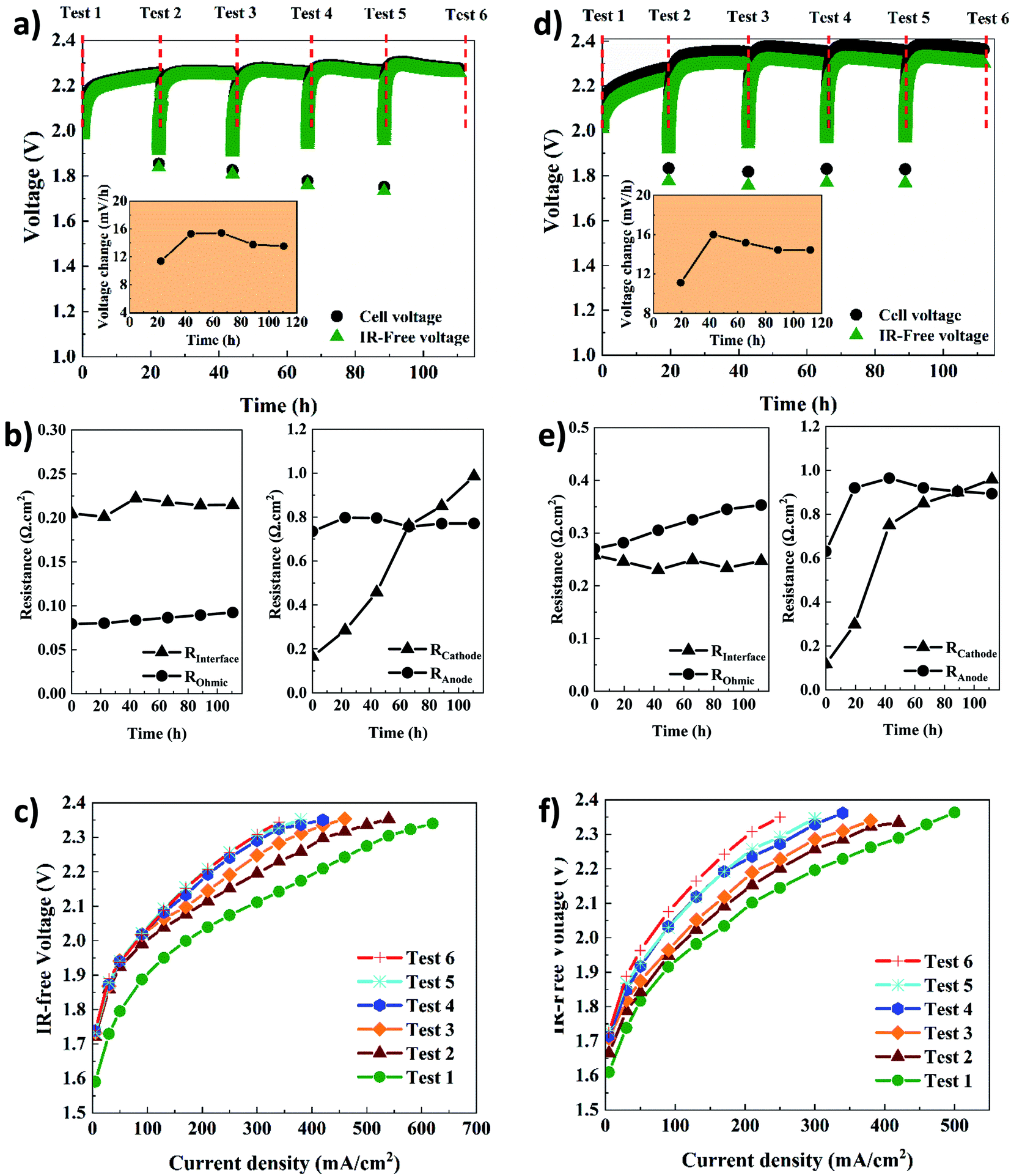 | ||
| Fig. 4 Electrochemical characterization of the AEMWE system using AF1-HNN8-50 (a–c) and AF1-HNN5-50 (d–f); (a and d) constant current tests via running steady-state electrolysis at 200 mA cm−2 (inset shows the voltage change rate), (b and e) Tafel slopes and exchange current values extracted from polarization curves, (c and f) different types of resistances extracted from EIS plots. Tests 1–6 correspond to the characterization techniques. Experimental conditions: 1 M KOH electrolyte on each side, 10 rpm flow rate and operation at 60 °C. | ||
The cell voltage change over time is shown in the inset of Fig. 4a and d. It should be noted that the rate of voltage change was calculated based on the start and end values of each test. A similar trend is seen for both systems. The rate increases extensively during the first 24 h but then, interestingly, stabilizes and even decreases, which could stem from remixing the electrolytes after each CC test. To prove the latter, an additional AEMWE experiment using AF1-HNN5-50 AEM was conducted without electrolyte remixing. As seen in Fig. S3,† the voltage shows an increasing trend and reaches the limit (2.4 V) after 50 h. Also, the initial voltages of the 2nd and 3rd repetitions are over 2 V and higher compared to that shown in Fig. 4d. Therefore, electrolyte remixing is very effective in voltage stabilization. Also, water crossover calculations were performed. Considering the reaction principles of the AEMWE system, water permeates through the membrane from the anode to the cathode, which causes dilution in the anolyte and concentration in the catholyte. To measure the water crossover, the volume of electrolytes on both sides was measured after each CC test (before remixing), and the results are presented in Tables S2–S5.† The theoretical calculations are based on Faraday's law by considering 3.5 as the hydration number of hydroxide ions (OH−(H2O)n, n = 3.5).36 The results show that during the first 20 h of each CC test, ∼47 mL water is theoretically transferred from the cathode to the anode side, but only ∼38 mL of this is found experimentally at the anode side, likely due to evaporation. The theoretical values based on only electrochemical reactions are in fairly good agreement with the experimental values. Still, the values deviate slightly due to different transport phenomena (diffusion, migration, and electroosmosis) as well as depending on the water uptake and thickness of the membranes. Overall, if the AEMWE system is operated without remixing the electrolytes, almost the entire electrolyte volume on the cathode will transfer to the anode after five repetitions. In this way, the contribution from Donnan and/or diffusion potentials to the membrane potential becomes more significant and leads to an additional overpotential.37
In addition, the voltage change rate of AEMWE using AF1-HNN5-50 is a little bit (1–2 mV h−1) higher when AF1-HNN8-50 is used. The origin of the voltage change was investigated using EIS analysis at the beginning and after each CC test. It should be mentioned that the equivalent circuit shown in Fig. S4† was used for EIS data analysis. As seen in Fig. 4b and e, all resistances contribute almost equally to the total resistance, except for the ohmic resistance. The most significant contribution is from changes in the OER kinetics (Ra) for the first three or four CC tests and, afterward, both OER (Ra) and HER (Rc) kinetics. The contribution from the ohmic resistance is very little when AF1-HNN8-50 is used. However, the ohmic resistance is four times higher when using AF1-HNN5-50 which also explains the larger difference between cell voltage and IR-free values. As all experimental conditions are the same except for the membrane, the higher ohmic resistance is due to the higher ionic transport resistance (lower water uptake and ion exchange capacity) of AF1-HNN5-50.
Considering the resistance change during the five CC tests, Rc experiences the most significant change and is likely related to nickel hydride phase formation on the cathode side. It is important to note that the layer formation is reversible and converted back to nickel during the shutdown time between each CC test.29,38,39 However, it is possible that the nickel hydride layer is only partially deformed due to limited time.29 This is probably why the thickness and extension of the layer during each CC test are more significant than during the previous test29,39—consequently, the number of active sites on the electrode decreases, which increases the Rc. The latter approach also influences the electrode-membrane contact resistance, which could be one of the reasons for the ohmic resistance increment of 14% and 23% for AEMWE using AF1-HNN8-50 and AF1-HNN5-50, respectively.
On the other hand, the contact resistance could also be due to the (hydr)oxide layer on the anode. Remarkably, the electrode-membrane contact resistance is higher in the case of AF1-HNN5-50 with a lower water uptake. It is difficult to say that membrane aging (backbone degradation or deactivation of cationic sites) contributes to this ohmic increment as (discussed later) the NMR analysis does not show any degradation sign. However, reduction in water uptake of membranes during the medium-term test and consequent reduction in ionic transport is likely another prime reason.
The interface resistance (RI) increases slightly and then stabilizes. The same trend is seen for the charge transfer resistance at the anode side, which supports that the interface resistance originates from the formation of a (hydr)oxide layer on the anode side.
The polarization curves (Fig. 4c and f) further confirm that the total resistance of AEMWE using AF1-HNN5-50 is higher than when AF1-HNN8-50 is used. The highest current density of 620 mA cm−2 was achieved at 2.37 V for AEMWE using AF1-HNN8-50 while 500 mA cm−2 was achieved at 2.39 V for AF1-HNN5-50. After five CC tests, the highest current density is reduced by around 50% for both systems.
The electrochemical performance of AEMWE using thin Aemion™ membranes (AF1-HNN8-25 and AF1-HNN5-25) was studied, and the results are presented in Fig. 5. The CC tests at 200 mA cm−2 (Fig. 5a and d) show that the voltage change in the first 22 h is significant but then shows no further significant increment. Compared to the presented results in Fig. 4a and d, the cell voltage for each CC test is slightly lower. For instance, in the case of AF1-HNN8-25, the cell voltage remains below 2.3 V. Also, the voltage difference between the cell voltage and IR-free values is smaller. The most obvious reason for these is the thinner membranes’ lower area resistance, leading to lower ohmic resistance. The same reason explains the voltage difference shown in Fig. 5a and d. This is also shown by the EIS data shown in Fig. 5b and e. The ohmic resistance values for both systems are almost half of the values shown in Fig. 4b and e and are in agreement with the data in Table 1. Thus, the voltage change rates are quite similar to those of the thicker membranes. The main contributions to the total resistance are still from OER and HER kinetics variation. Interestingly, the interface resistance (RI) remains in the same range as that of the AEMWE system using thick membranes. More notably, the charge transfer resistance at the cathode and anode sides shows the same trend. As all experimental conditions for tests shown in Fig. 4 and 5 are the same except the thickness of membranes, it is therefore not surprising to observe more or less similar RI, Ra, and Rc. This provides another indication that the membrane properties do not affect the kinetics and interface resistances. With respect to the polarization curves (Fig. 5c and f), the highest current density of 620 mA cm−2 and 500 mA cm−2 at 2.3 V for the AEMWE system using AF1-HNN8-25 and AF1-HNN5-25 were achieved, respectively. However, after five CC tests, the current density values dropped to 460 mA cm−2 and 250 mA cm−2.
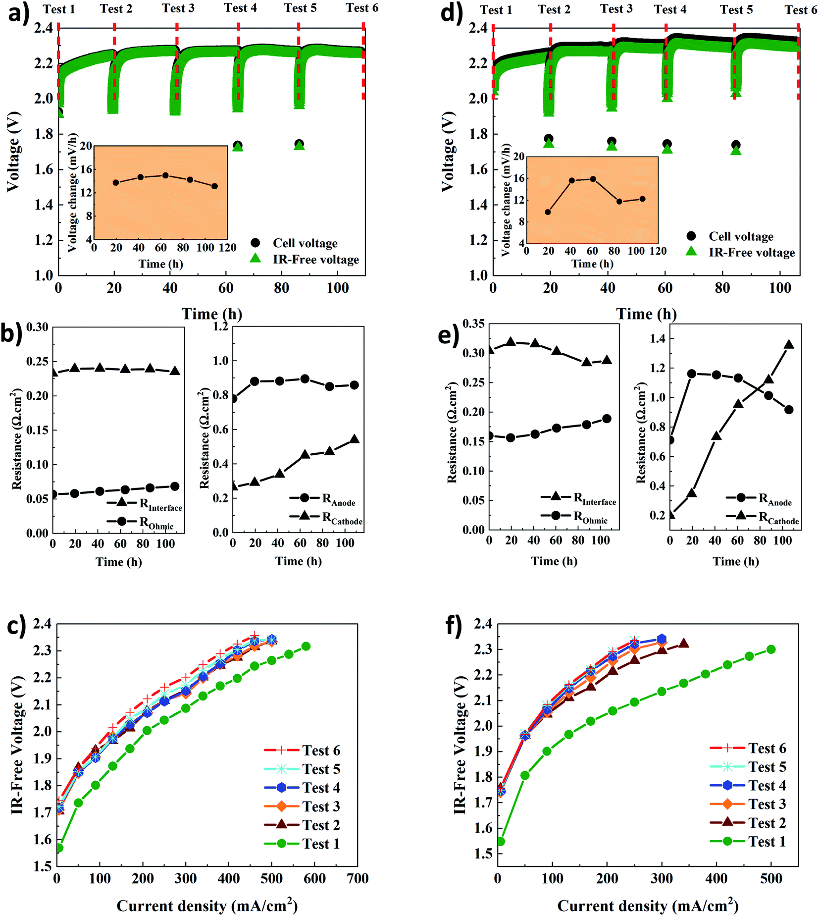 | ||
| Fig. 5 Electrochemical characterization of the AEMWE system using AF1-HNN8-25 (a–c) and AF1-HNN5-25 (d–f); (a and d) constant current tests via running steady-state electrolysis at 200 mA cm−2 (inset shows the voltage change rate), (b and e) Tafel slopes and exchange current values extracted from polarization curves, (c and f) different types of resistances extracted from EIS plots. Tests 1–6 correspond to the characterization techniques. Experimental conditions: 1 M KOH electrolyte on each side, 10 rpm flow rate and operation at 60 °C. | ||
Among the Aemion™ AEMs, the chemical stability of AF1-HNN8-50 was analyzed by 1H NMR spectroscopy before and after five CC tests. Fig. 6 shows the spectrum of the pristine AF1-HNN8-50 membrane, which closely resembles the spectrum of HMT-PBI.26 Holdcroft et al. previously reported that major degradation of HMT-PBI occurs via ring-opening through an OH− attack at the C2 position of the imidazolium group. The ring-opening degradation of imidazolium leads to the formation of N–H groups and the corresponding proton signals appear between 5.5 and 4.4 ppm in the NMR spectrum. Notably, the spectrum of pristine AF1-HNN8-50 showed no signals in the 6.0–4.5 ppm region. Hence, this area was integrated and compared with the signal of the 12 aromatic protons in the 9.20–6.30 ppm region to obtain the value of z using eqn (2). In addition, Fig. 6 shows the spectrum of AF1-HNN8-50 (in Br− form) after five CC tests. As seen, the spectrum does not show any significant changes, and only very minor signals related to the degradation are observed in the region of 6.0–4.5 ppm. Consequently, the extent of degradation (ionic loss) of AF1-HNN8-50 after AEMWE tests could not be quantitatively determined.
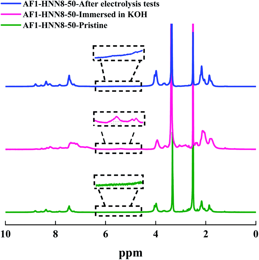 | ||
| Fig. 6 1H NMR spectra of AEM HNN8-50, in the pristine form (lower), after storage in 2 M KOH at 90 °C for one month (mid), and after the electrolysis test (upper). The data were recorded in DMSO-d6. | ||
On the other hand, the medium-term chemical stability of AF1-HNN8-50 and AF1-HNN5-50 was studied by an ex situ experiment. After exposure to 2 M KOH at 90 °C for one month, the samples were converted to their Br− form and analysed by 1H NMR spectroscopy. Fig. 6 and S5† show the spectra of AF1-HNN8-50 and AF1-HNN5-50, respectively. As seen, significant changes were observed in the aromatic region of these spectra and clearly distinct degradation signals appeared in the 6.0–4.5 ppm region. These new signals are characteristic of N–H groups formed due to ring-opening degradation of the benzimidazolium cations.26 The extent of ionic loss for AF1-HNN8-50 was estimated to be 14%, while AF1-HNN5-50 showed an ionic loss close to 7%. Also, both membranes disintegrated into small pieces. Hence, AF1-HNN8-50 was found to be more susceptible to degradation compared to AF1-HNN5-50. The lower ionic loss of AF1-HNN5-50 might be attributed to the lower electrolyte uptake of this membrane, as reflected in the lower swelling ratio (Table 1), which reduces the probability of OH− attack. Accordingly, from the viewpoint of medium-term chemical stability, AF1-HNN5-50 appears to be a better candidate than AF1-HNN8-50 under the investigated conditions.
Conclusions
The medium-term (electro)chemical performance of Aemion™ AEMs was successfully studied using in situ and ex situ tests. All AEMs showed stable performance for more than 100 h during galvanostatic AEMWE tests using nickel felt as the electrode. Among the AEMs, AF1-HNN8-25 showed the highest ionic conductivity and lowest ohmic resistance when used in AEMWE tests. Also, the lowest overpotential and total resistance were achieved. Due to water crossover through the membrane and electrolyte imbalance, it was found that remixing electrolytes is quite beneficial for voltage stability in medium-term tests. EIS analysis revealed that charge transfer resistances at the cathode and anode sides have the highest contribution to the total resistance and resistance increase after each CC test.The chemical stability of AF1-HNN8-50 after medium-term AEMWE tests was confirmed by 1H NMR analysis which showed no chemical degradation. However, soaking AEMs in 2 M KOH at 90 °C for one month caused both chemical degradation and mechanical disintegration. AF1-HNN8-50 and AF1-HNN5-50 showed 14 and 7% ionic loss after a month, respectively. In addition, they disintegrated into small pieces. Overall, the current study reveals that Aemion™ AEMs are good candidates for medium-term water electrolysis tests under carefully controlled experimental conditions.
Author contributions
Amirreza Khataee: conceptualization, methodology, validation, investigation, writing – original draft, writing – review & editing. Anuja Shirole: validation, writing – review & editing, investigation. Andries Krüger: validation, writing – review & editing, investigation. Patric Jannasch: validation, writing – review & editing. Ann Cornella: writing – review & editing, advising, funding acquisition.Conflicts of interest
The authors declare that they have no known competing financial interests or personal relationships that could have appeared to influence the work reported in this paper.Acknowledgements
This work was conducted as part of the HYBRIT research project RP1. We gratefully acknowledge financial support from the Swedish Energy Agency. HYBRIT (Hydrogen Breakthrough Ironmaking Technology) is a joint initiative of the three companies SSAB, LKAB and Vattenfall with the aim of developing the world's first fossil-free ore-based steelmaking route.References
- S. Shiva Kumar and V. Himabindu, Mater. Sci. Energy Technol., 2019, 2, 442–454 Search PubMed.
- J. Brauns and T. Turek, Processes, 2020, 8, 248 CrossRef CAS.
- J. Chi and H. Yu, Chin. J. Catal., 2018, 39, 390–394 CrossRef CAS.
- M. Momirlan and T. N. Veziroglu, Int. J. Hydrogen Energy, 2005, 30, 795–802 CrossRef CAS.
- K. Ayers, N. Danilovic, R. Ouimet, M. Carmo, B. Pivovar and M. Bornstein, Annu. Rev. Chem. Biomol. Eng., 2019, 10, 219–239 CrossRef CAS PubMed.
- D. Henkensmeier, M. Najibah, C. Harms, J. Žitka, J. Hnát and K. Bouzek, J. Electrochem. Energy Convers. Storage, 2020, 18, 024001 CrossRef.
- M. Schalenbach, A. R. Zeradjanin, O. Kasian, S. Cherevko and K. J. Mayrhofer, Int. J. Electrochem. Sci., 2018, 13, 1173–1226 CrossRef CAS.
- H. A. Miller, K. Bouzek, J. Hnat, S. Loos, C. I. Bernäcker, T. Weißgärber, L. Röntzsch and J. Meier-Haack, Sustainable Energy Fuels, 2020, 4, 2114–2133 RSC.
- O. Schmidt, A. Gambhir, I. Staffell, A. Hawkes, J. Nelson and S. Few, Int. J. Hydrogen Energy, 2017, 42, 30470–30492 CrossRef CAS.
- D. Li, A. R. Motz, C. Bae, C. Fujimoto, G. Yang, F.-Y. Zhang, K. E. Ayers and Y. S. Kim, Energy Environ. Sci., 2021, 14, 3393–3419 RSC.
- I. V. Pushkareva, A. S. Pushkarev, S. A. Grigoriev, P. Modisha and D. G. Bessarabov, Int. J. Hydrogen Energy, 2020, 45, 26070–26079 CrossRef CAS.
- D. Li, E. J. Park, W. Zhu, Q. Shi, Y. Zhou, H. Tian, Y. Lin, A. Serov, B. Zulevi, E. D. Baca, C. Fujimoto, H. T. Chung and Y. S. Kim, Nat. Energy, 2020, 5, 378–385 CrossRef CAS.
- A. Carbone, S. C. Zignani, I. Gatto, S. Trocino and A. S. Aricò, Int. J. Hydrogen Energy, 2020, 45, 9285–9292 CrossRef CAS.
- A. K. Niaz, A. Akhtar, J.-Y. Park and H.-T. Lim, J. Power Sources, 2021, 481, 229093 CrossRef CAS.
- Q. Xu, S. Z. Oener, G. Lindquist, H. Jiang, C. Li and S. W. Boettcher, ACS Energy Lett., 2020, 6, 305–312 CrossRef.
- S. Holdcroft and J. Fan, Curr. Opin. Electrochem., 2019, 18, 99–105 CrossRef CAS.
- S. Maurya, S.-H. Shin, Y. Kim and S.-H. Moon, RSC Adv., 2015, 5, 37206–37230 RSC.
- K. M. Hugar, H. A. Kostalik and G. W. Coates, J. Am. Chem. Soc., 2015, 137, 8730–8737 CrossRef CAS PubMed.
- J. Fan, S. Willdorf-Cohen, E. M. Schibli, Z. Paula, W. Li, T. J. G. Skalski, A. T. Sergeenko, A. Hohenadel, B. J. Frisken, E. Magliocca, W. E. Mustain, C. E. Diesendruck, D. R. Dekel and S. Holdcroft, Nat. Commun., 2019, 10, 2306 CrossRef PubMed.
- H. Long and B. Pivovar, J. Phys. Chem. C, 2014, 118, 9880–9888 CrossRef CAS.
- H. Ma, H. Zhu and Z. Wang, J. Polym. Sci., Part A: Polym. Chem., 2019, 57, 1087–1096 CrossRef CAS.
- A. G. Wright, T. Weissbach and S. Holdcroft, Angew. Chem., Int. Ed., 2016, 55, 4818–4821 CrossRef CAS PubMed.
- O. D. Thomas, K. J. W. Y. Soo, T. J. Peckham, M. P. Kulkarni and S. Holdcroft, J. Am. Chem. Soc., 2012, 134, 10753–10756 CrossRef CAS PubMed.
- A. G. Wright and S. Holdcroft, ACS Macro Lett., 2014, 3, 444–447 CrossRef CAS PubMed.
- A. G. Wright, J. Fan, B. Britton, T. Weissbach, H.-F. Lee, E. A. Kitching, T. J. Peckham and S. Holdcroft, Energy Environ. Sci., 2016, 9, 2130–2142 RSC.
- P. Fortin, T. Khoza, X. Cao, S. Y. Martinsen, A. Oyarce Barnett and S. Holdcroft, J. Power Sources, 2020, 451, 227814 CrossRef CAS.
- A. Khataee, E. Dražević, J. Catalano and A. Bentien, J. Electrochem. Soc., 2018, 165, A3918–A3924 CrossRef CAS.
- A. E. Mauer, D. W. Kirk and S. J. Thorpe, Electrochim. Acta, 2007, 52, 3505–3509 CrossRef CAS.
- D. M. Soares, O. Teschke and I. Torriani, J. Electrochem. Soc., 1992, 139, 98–105 CrossRef CAS.
- D. S. Hall, C. Bock and B. R. MacDougall, J. Electrochem. Soc., 2013, 160, F235 CrossRef CAS.
- J. Song, L. Wang, A. Zibart and C. Koch, Metals, 2012, 2, 450–477 CrossRef CAS.
- S. L. Medway, C. A. Lucas, A. Kowal, R. J. Nichols and D. Johnson, J. Electroanal. Chem., 2006, 587, 172–181 CrossRef CAS.
- W. Liu, L. Sun, Y. Luo, R. Wu, H. Jiang, Y. Chen, G. Zeng and Y. Liu, Appl. Surf. Sci., 2013, 280, 193–200 CrossRef CAS.
- G. S. Frankel, J. Electrochem. Soc., 1998, 145, 2186–2198 CrossRef CAS.
- K. Cysewska, G. Cempura, J. Karczewski, M. Łapiński, P. Jasiński and S. Molin, Mater. Lett., 2020, 258, 126759 CrossRef CAS.
- M. Śmiechowski and J. Stangret, J. Phys. Chem. A, 2007, 111, 2889–2897 CrossRef PubMed.
- N. Kimura, H. Matsumoto, Y. Konosu, R. Yamamoto, M. Minagawa and A. Tanioka, J. Colloid Interface Sci., 2005, 286, 288–293 CrossRef CAS PubMed.
- W. Palczewska, in Advances in Catalysis, ed. D. D. Eley, H. Pines and P. B. Weisz, Academic Press, 1975, vol. 24, pp. 245–291 Search PubMed.
- L. Schlapbach, A. Seiler, F. Stucki and H. C. Siegmann, J. Less-Common Met., 1980, 73, 145–160 CrossRef CAS.
Footnote |
| † Electronic supplementary information (ESI) available. See https://doi.org/10.1039/d2ta03291k |
| This journal is © The Royal Society of Chemistry 2022 |