
 Open Access Article
 This Open Access Article is licensed under a Creative Commons Attribution-Non Commercial 3.0 Unported Licence
The degradation and recovery behavior of mixed-cation perovskite solar cells in moisture and a gas mixture environment†
George
Wenson
ab,
Harshul
Thakkar
a,
Hsinhan
Tsai
 a,
Joshua
Stein
c,
Rajinder
Singh
a and
Wanyi
Nie
*a
a,
Joshua
Stein
c,
Rajinder
Singh
a and
Wanyi
Nie
*a
aLos Alamos National Laboratory, 30 Bikini Atoll, Los Alamos, NM 87545, USA. E-mail: wanyi@lanl.gov
bHonors College School of Engineering, Rutgers University, New Brunswick, NJ 008854, USA
cSandia National Laboratory, Albuquerque, New Mexico 87123, USA
First published on 30th May 2022
Abstract
Metal halide perovskites are not only established as champion materials for conversion of solar energy to electricity but are also one of the promising candidates for solar driven fuel generation. In this paper, we report the photovoltaic devices' operational stability investigation in dry and humid nitrogen (N2) and carbon dioxide (CO2) environments. By monitoring the behavior of a mixed-cation mixed-halide perovskite solar cell under constant 1-sun illumination in a gas mixture, we find that relative humidity plays a central role in expediting degradation. Interestingly, rapid degradation is a recoverable process once the light source is removed at the same humidity level. After a detailed analysis of the current–voltage characteristics, an increase in the series resistance is observed when exposed to continuous illumination. This is validated by surface resistivity measurements on both sides of the device. Photoluminescence (PL) characterization indicates a temporary decrease in the PL intensity and can be expedited by higher relative humidity levels. Our study reports behavior of perovskite solar cells in dry and wet N2 and CO2 environments that is necessary for solar-to-fuel applications like CO2 reduction and water splitting in the gas phase.
Introduction
Industrial and research communities are working to find technologies that will enable them to reach 2030 greenhouse gas emission reduction targets.1 Utilizing forms of renewable energy such as solar energy is one of the main strategies to address the climate crisis. There are many ways of converting solar energy into other forms; one popular application is solar fuel production via electrochemistry reactions. Such reactions require a high efficiency photo-catalyst to facilitate the reaction and the selectivity of the end product, which forms the core topic of the research community.Halide perovskite semiconductors have been recently recognized as potential champion materials for optoelectronic applications such as photovoltaics and light-emitting diodes. The perovskite photovoltaic (PV) technologies have shown great promise in converting solar energy to electrical power. The field has made substantial progress in pushing power conversion efficiencies over 25% for cells2–4 and extending the operational lifetimes of perovskite PV that are required for commercialization. Alternate routes of utilizing perovskite materials for clean energy generation are being rigorously investigated. Notably, perovskite materials are being considered for driving photocatalytic reactions especially for solar driven CO2 reduction,5–7 which can generate alternative fuels for energy while decarbonizing the environment. Perovskite nanocrystals with their tunable bandgap8–12 and long carrier lifetimes13–17 have been demonstrated as a promising photo-catalyst candidate to break stable C![[double bond, length as m-dash]](https://www.rsc.org/images/entities/char_e001.gif) O bonds, leading to the formation of hydrocarbons.18–20 Very recently, perovskite solar cells have been used as an electron source to drive CO2 reduction.14,21–25 For all these applications, direct contact with water molecules or acid is required to lower the reaction barrier.26–28 However, it is known that water can quickly degrade the perovskite layer upon contact, which will cause device failure.26–29 For instance, the hydroscopic nature of the amine group in the cation salt of perovskite can cause its dissolution in water and revert the perovskite structure to the precursor phase. To circumvent this problem, Zhang et al. built an epoxy wrapped cell enclosure to extend the lifetime, and successfully demonstrated CO2 reduction.29 Others have explored non-aqueous environments, such as ionic liquid baths and polar aprotic solvent systems, that do not damage the perovskite materials for electrochemical reactions.30,31
O bonds, leading to the formation of hydrocarbons.18–20 Very recently, perovskite solar cells have been used as an electron source to drive CO2 reduction.14,21–25 For all these applications, direct contact with water molecules or acid is required to lower the reaction barrier.26–28 However, it is known that water can quickly degrade the perovskite layer upon contact, which will cause device failure.26–29 For instance, the hydroscopic nature of the amine group in the cation salt of perovskite can cause its dissolution in water and revert the perovskite structure to the precursor phase. To circumvent this problem, Zhang et al. built an epoxy wrapped cell enclosure to extend the lifetime, and successfully demonstrated CO2 reduction.29 Others have explored non-aqueous environments, such as ionic liquid baths and polar aprotic solvent systems, that do not damage the perovskite materials for electrochemical reactions.30,31
While solving the stability problem is critical, it is also important to better understand the perovskite material behaviors in a gas mixture of water and CO2 or a nitrogen environment.25,32–34 Perovskite solar cells are known to be sensitive to the moisture in the environment where the performance drops rapidly in the presence of high humidity. But uniquely, the devices can also self-heal once the light is removed.35–37 The self-healing effect has been attributed to defect formation,38 ion migration35,36 and structural deformation.39
Recently, mixed-cation mixed-halide perovskites have been developed for high efficiency solar cells. The addition of ionic liquid has been proven to be a good strategy to stabilize the performance. But the cell stability of this system has not been investigated at various humidity levels. This is motivated by a recent study to investigate PSC device and photocatalysis operational stability under constant 1-sun illumination in various humidity/gas mixtures.32,40 We observe a direct relation between the device's degradation rate and the relative humidity (R.H.) levels in the CO2 gas. Interestingly, most of the performance loss can be restored when the light is turned off in the same R.H./CO2 environment. By analyzing the current–voltage characteristics in greater detail, such as short circuit current density (JSC), open circuit voltage (VOC), and current–voltage curve slopes, we found that the series resistance of the cell increases upon illumination in a dry gas environment, and water molecules greatly advance such a change. The moisture assisted degradation is accompanied by a photoluminescence (PL) intensity drop. Our study concludes that R.H. has a direct impact on the cells' performance under constant illumination, and the performance losses can be restored in the same humid environment in the dark. These results are necessary when using the cells in a high humidity environment to drive reactions like CO2 reduction or methane generation.
Experimental section
Materials
Lead(II) iodide (PbI2, 99.999%), lead(II) bromide (PbBr2, >98%), bathocuproine (BCP, 99.99%), formamidinium iodide (FAI, >99%), methylammonium iodide (MAI, >99%), cesium iodide (CsI, >99.9%), poly[bis(4-phenyl)(2,4,6-trimethylphenyl)amine], poly(triaryl amine) (PTAA, average Mn 7000–10![[thin space (1/6-em)]](https://www.rsc.org/images/entities/char_2009.gif) 000), N,N-dimethylmethanamide (DMF, anhydrous, 99.8%), dimethyl sulfoxide (DMSO, anhydrous, >99.9%) and chlorobenzene (CB, anhydrous, 99.8%) were purchased from Sigma-Aldrich and used without further purification. [6,6]-Phenyl-C61-butyric acid methyl ester (C60-PCBM) was purchased from Nano-C and used as received.
000), N,N-dimethylmethanamide (DMF, anhydrous, 99.8%), dimethyl sulfoxide (DMSO, anhydrous, >99.9%) and chlorobenzene (CB, anhydrous, 99.8%) were purchased from Sigma-Aldrich and used without further purification. [6,6]-Phenyl-C61-butyric acid methyl ester (C60-PCBM) was purchased from Nano-C and used as received.
Perovskite thin film and device fabrication
The perovskite photovoltaic has a device architecture of indium tin oxide (ITO)/PTAA/perovskites/PCBM/BCP/top electrode. The ITO substrates (7 Ω per square, Solaronix) were pre-cleaned and treated with ozone plasma before fabricating a hole transport layer. The PTAA solution (1 mg ml−1 in CB) was spun cast on an ITO substrate at 5k rpm for 30 s and then annealed at 100 °C for 20 minutes. The perovskite solution was made using 1.3 M of (Cs0.05FA0.8MA0.2PbI2.7Br0.3) in DMF/DMSO (4:1) mix solution. The perovskite layers were prepared inside an argon-filled glovebox with a one-step antisolvent process. PCBM solution (20 mg ml−1 in CB) was spun cast on the perovskite layer at 4k rpm, followed by BCP (0.5 mg ml−1 in IPA) solution which was fabricated with 4k rpm. A 100 nm silver or gold layer was deposited on the final top electrode using thermal evaporation with a working area of 0.1 cm2 defined by using a shadow mask under high vacuum (10−8 Torr).
Environmental chamber and illumination conditions
The perovskite devices were encased in an environmental chamber (reactor) and exposed to CO2 with the relative humidity between 0 and 90% where the humidity was controlled by using a humidifier, as shown in Scheme 1. Scheme 1(a) shows the photoreactor system design and the actual system is shown in Scheme 1(b). The reactor was first purged with nitrogen (N2) for 20 minutes to remove moisture, oxygen and other contaminants typically found in ambient air followed by dry and humid CO2. To investigate the operation stability of these perovskite devices, a cyclic experiment (90 min with light-on/60 min dark) was carried out with CO2/H2O (50% R.H.) for a multiple cycle test.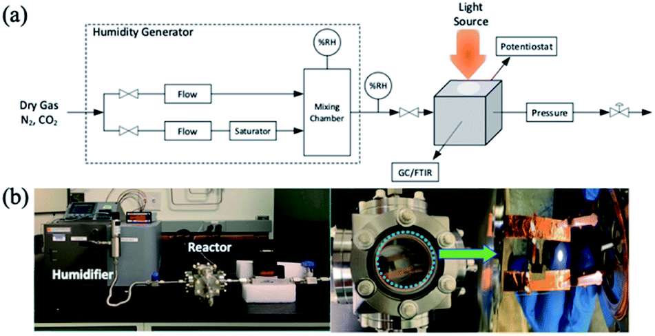 | ||
| Scheme 1 (a) Photoreactor system design and (b) reactor system for perovskite devices. | ||
Device stability test procedures
Once the perovskite devices were prepared, the product needed to be wired to form a working photovoltaic device. A glass slide was divided into two and the perovskite was attached with tape to the center of the half slide. Pieces of copper tape were placed on the glass slide on either side of the perovskite sample. A multimeter was used to identify which electrodes provided the greatest potential and pieces of copper tape were used to connect the gold electrodes to the copper tape on the side of the slide. These connections were overlayed with (Taiwan Carbon Materials Corp. X-CONDUCTOR™ Conductive Series (XD-R06)) silver paint to strengthen the connection between the electrode and the tape. On the positive terminal, silver paint was used to connect the copper tape to the ITO conductive glass underneath the perovskite layer. The potential of the solar cell would then be measured with a multimeter as a quality check to determine whether it functions or not. The devices underwent another round of quality control by performing preliminary current–density–voltage (J–V) curve measurements under ambient atmospheric conditions and 1-sun illumination (Class ABA solar simulator (Newport)). If the connections were done properly, then the J–V curves would yield clean data. Only after the devices passed these two tests, would they be allowed to go through to the data collection phase.The devices were loaded into an environmental chamber with a window on the top side to let light into the apparatus. The chamber would be connected to a gas mixer as shown in Scheme 1(a) and (b), which would be used to control the humidity levels inside the environmental chamber. After the desired humidity level was reached, the environmental chamber would be wired to a Keithley 2400 source meter unit to measure the J–V curves for the device. The standard test would involve the environmental chamber being under constant illumination for two hours, after which the lamp would be turned off to observe the behavior of the cell in the dark. The sample would be re-illuminated only during the times when the J–V curve data were taken to ensure minimal amounts of degradation.
Results and discussion
Perovskite solar cell performance
The perovskite solar cell investigated in this work following an inverted p–i–n structure is shown in Fig. 1(a). Briefly, a pre-cleaned indium tin oxide (ITO) substrate is coated with a p-type polymer layer (poly[bis(4-phenyl)(2,4,6-trimethylphenyl])amine, PTAA) as the hole transport layer (HTL). The perovskite absorbing layer is spin coated on the PTAA surface employing a popular mixed-cation, mixed-halide perovskite composition (Cs0.05FA0.75MA0.2PbI2.7Br0.3) and is converted by an antisolvent approach.16,41–45 The perovskite layer is processed with ionic liquid as an additive in the precursor in order to suppress light-induced ion migration.46,47 The n-type electron transport layer (ETL) is formed by spin coating a layer of phenyl-C61-butyric acid methyl ester (PCBM) and a thin bathocuproine (BCP) layer on top of the perovskite. The device is completed by metallization with gold or silver. Here, silver was selected for efficiency characterization due to a better band alignment, and gold is selected for stability testing in gas environments to reduce the corrosion effect. The device dimensions are described in the experimental section. The device was first characterized by current–density–voltage (J–V) sweeps under 1-sun illumination. | ||
| Fig. 1 Photovoltaic device characterization and setup. (a) Device structure used in this study. (b) Typical dark (grey) and light (red) current–density–voltage curves; (c) light current–density–voltage characteristics when the voltage is swept from different polarities for the hysteresis behavior test. Both (b) and (c) are taken under a solar simulator with 1-sun intensity and a AM1.5G standard solar irradiation filter. (d) External quantum efficiency and the integrated short circuit current density taken under monochromatic light sources. (e) Gas environment setup used in this study. The device is mounted in a vacuum chamber, with the transparent electrode side facing the top quartz window where the light comes through. | ||
Fig. 1(b) shows the J–V curves under dark and illuminated conditions. The dark and light J–V curves illustrate a typical diode behavior with the current on-off ratio of 4–7 orders of magnitude (Fig. S1 in ESI†) under the voltage range. In addition, forward and reverse voltage sweeps with a sweep rate of 10 mV s−1 are performed to test the hysteresis behavior in perovskite photovoltaics. Since the forward and reverse scans overlap well, the device in Fig. 1(c) is of high quality and free from hysteresis. The average power conversion efficiency (PCE) of the solar cells is 20.45 ± 0.32% with an open-circuit voltage (VOC) of 1.09 ± 0.03 V, short-circuit current density (JSC) of 23.56 ± 0.21 mA cm−2 and fill-factor (F.F.) of 79.84 ± 0.63%. The external quantum efficiency (EQE) is plotted and shown in Fig. 1(d) with the integrated photocurrent extracted from the EQE curve. The integrated current density (23.16 mA cm−2) obtained from the EQE curve matches with the measured JSC from the J–V characteristic curves in Fig. 1(b) with less than 2% discrepancy. After confirming the device's performance, we then fabricated devices using the same processing conditions and replaced the top electrode with gold (Au). The Au devices were first characterized using dark J–V curves in air (Fig. S2†) and then transferred to a custom vacuum chamber (Fig. 1(e), also illustrated in Scheme 1 in the ESI†) outfitted with a quartz window and electrical feedthroughs. The vacuum chamber was initially pumped and purged with testing gas (N2 or CO2 with R.H. = x%, where x = 0, 20, 40, 60, 90) before data collection. The testing conditions in the dark and a 1-sun illumination environment are controlled by using a class ABA solar simulator with 1-sun equivalent intensity (100 mW cm−2) after an air mass 1.5G filter.
Operational stability tests of the devices
Detailed summaries of the solar cell's responses to different gas mixture environments are shown in Fig. 2. Fig. 2(a)–(d) show the time evolution of the device's figures of merit, namely VOC, JSC, fill factor (F.F.) and power conversion efficiency (PCE), at different R.H. levels in CO2 environments under constant illumination. The device's responses in dry nitrogen and dry CO2 (repeat) air are also studied and shown in Fig. S3–S5 in the ESI.† By the end of a 2 hour constant illumination period, the VOC drops by 5–15% when R.H. increases in the environment, whereas JSC decreases by 40–60%. In both cases, a higher R.H. accelerates the degradation in the first 0–20 min testing period. The F.F. in Fig. 2(c) drops moderately by 10–20%, and R.H. also accelerates its degradation. Interestingly, in the 20–120 minute range, the degradation rates for VOC and JSC slow down and reach stabilized states only under high R.H. conditions. The overall PCE's degradation curve in Fig. 2(d) is determined by the JSC, which loses its peak value most significantly. The raw J–V curves are plotted and shown in Fig. S6–S8 in the ESI.† Also, light appears to be a vital element in the degradation of the solar cell. Fig. 2(a) and (b) show that when the device is no longer exposed to light, the normalized figures of merit are restored back to values close to the measurements at the beginning of the experiment. The device does not appear to be permanently damaged as can be seen in Fig. 2(e) within this testing period. To show reproducibility, we tested the devices under multiple light on/off cycles in an R.H. = 90% environment, and the difference in performance between cycles was minimal. Fig. 2(f) shows the healing effect of the device, which was tested at R.H. = 90% under dark and light cycling, and it is allowed to fully recover after being tested for 2 hours under the dark condition. This result shows how significant the light contribution is to the degradation of the solar cell. Also noticeably, at high R.H. = 90%, the device can recover its original performance within the testing period (i.e., 120 min). Over longer-term exposure, the device's performance will ultimately drop (Fig. S12†) due to permanent damage to the perovskite materials as accepted by the established degradation mechanism.48–50 | ||
| Fig. 2 Summary of the device stability results. Time evolution of the normalized (a) VOC, (b) JSC, (c) fill factor and (d) PCE at various R.H. levels and in CO2 gas environments under constant illumination (0–120 min) and in the dark (120–140 min). (e) Time evolution of the device's normalized VOC (upper panel) and JSC (lower panel) under multiple light on (yellow region) and light off (grey region) cycles. (f) The time evolution of the normalized JSC measured under constant illumination, and its recovery in 2 hours of darkness at 90% R.H. | ||
Fig. S11 in the ESI† compares the time evolution of the solar cell's figures of merit upon aging in dry N2 and CO2 gases under constant illumination. The device's degradation behaviors are very similar in both environments, indicating that CO2 does not play a special role in the degradation behaviors.
Investigation of the solar cells' degradation mechanism
To gain a deeper insight into the degradation mechanism, a detailed analysis of the J–V characteristics is carried out and the results are summarized in Fig. 3. The dark J–V characteristics of a fresh device are compared in Fig. 3(a) after 1 hour illumination (degraded) and recovered in the dark after 100 min (recovered) under a CO2/H2O gas mixture environment with R.H. = 90%. The recovered curve (100 min) almost overlaps with the fresh curve, whereas the degraded device exhibits severe hysteresis (red dashed line). We have also checked perovskite films' crystallinity with the X-ray diffraction (XRD) patterns, and morphology via scanning electron microscopy (Fig. S9†) and UV-vis absorption (Fig. S10†) before and after gas exposure in ESI,† to confirm that the bulk composition remains unchanged within the testing period. In addition, the forward injection current increases for the degraded state which is reflected by the shift of the minimum point and the steeper slope at the forward bias. | ||
| Fig. 3 Detailed J–V characteristic curve analysis. (a) Typical J–V curves measured in the dark for a device being exposed to water/CO2 with R.H. = 90% at fresh, degraded and recovered status. The dotted lines are the same data being plotted in a linear-log scale. The J–V curves were measured by scanning from different bias polarities to observe the hysteresis. (b) The corresponding light J–V curves and the normalized curves are shown in (c). Time evolution of the extracted normalized (d) ROC values and (e) RSC values for devices measured in dry CO2 and humid CO2 environments. | ||
Fig. 3(b) presents the device's J–V curves under 1-sun illumination when it is in fresh, degraded and recovered states. To compare the slopes at the two fundamental points (i.e., open-circuit (OC) and short-circuit (SC)), the normalized curves are shown in Fig. 3(c). It is clear that the slope does not change near the SC point for all conditions, whereas the slope changes more significantly near OC once the device is degraded, suggesting an increase in series resistance. This indicates that the humidity induced degradation mainly affects the current loss near the open circuit, which is related to the charge collection barrier near a low field. To compare the resistance at open circuit (ROC) at all times when R.H. = 0% to 90%, Fig. 3(d) shows the time evolution of the normalized ROC under constant illumination (0–120 min) and in the dark (120–150 min). Interestingly, the change in ROC is concurrent with the light on/off cycles in both dry and humid environments. The high humidity level expedites the ROC's increase under illumination, and the ROC drops back to the original value once light is removed which is similar to the device efficiency evolution shown in Fig. 2. In contrast, the time evolution of resistivity under the short circuit condition (RSC) does not follow the light on/off cycles and is not affected by the relative humidity levels, as shown in Fig. 3(e). From these measurements, it is concluded that the ROC's increase accompanies the device degradation, and its rate is also heavily impacted by the environmental conditions such as light and humidity whereas the RSC is less affected.
To further understand the changes in electrical characteristics of the perovskite thin film when exposed to different gas environments, we examined the thin films' surface resistivity and photoluminescence changes under light and dark conditions. Fig. 4(a) shows two lateral device structures used for surface resistivity measurements. Here, we put two electrodes on the top of the perovskite/PCBM surface or deposit the perovskite on ITO with inter-digited patterns in order to probe the resistivity changes at the top and bottom interfaces respectively in moisture and light. Fig. 4(b) and (c) show the normalized resistivity evolution under one light–dark cycle in an R.H. = 90% environment. Interestingly, both resistivities measured at the top surface and bottom surface increase upon illumination in the R.H. = 90% condition and the values decrease to the original state once the light is off. These behaviors agree with the performance changes observed in Fig. 2, indicating that both interfaces are affected by illumination and humidity conditions. In addition, the increase in the surface resistivity values is consistent with the observation of the ROC increase observed in Fig. 3, suggesting that insulating regions are formed when the light is on in a high humidity environment.
 | ||
| Fig. 4 Degradation mechanism investigations. (a) Schematic illustration of the device structures used for the lateral resistivity measurements; (b and c) the resistivity evolution under constant illumination and recovery in the dark where R.H. = 90% for both interfaces. Photoluminescence (PL) peak intensity and peak position for perovskite thin films (d) in 0% R.H. and (f) in 60% R.H. The corresponding PL spectra collected at various time points (A–E) are plotted in (e) and (g) respectively. The laser is CW 531 nm with a power density of 1 W cm−2. | ||
Furthermore, we performed PL stability tests under various relative humidity environments (R.H. = 0–60%) to deepen our understanding from a material perspective. Fig. 4(d) and (f) show the time evolution of the perovskite thin films' PL peak intensity (blue) and PL peak position (red) at R.H. = 0% and R.H. = 60% respectively. During the test period, the PL height remains unchanged at R.H. = 0% in each laser on/off cycle. In sharp contrast, once the R.H. increases to 60%, the PL height rapidly decreases upon laser irradiation, and can be restored to half the original value in the dark after multiple cycles. The peak positions, on the other hand, are not significantly affected by laser irradiation nor altered by R.H. values within the testing period. This is reflected in Fig. 4(e) and (g) where the PL spectra are plotted for R.H. = 0% and R.H. = 60%. In the mixed-cation, mixed-halide perovskite materials, light induced ion migration and phase segregation have been reported.47,51 PL peak shifts or line shape changes are often employed to probe halide segregation. In this case, severe phase segregation induced PL line shape changes are not obvious even under a humid environment likely because of the addition of the ionic liquid that has been proven to be effective suppressing ion migrations.46,47 Considering the resistivity changes shown in Fig. 4(b) and (c), the PL intensity drop can be attributed to the carrier scattering from the increased series resistance.
To briefly summarize the experimental observations, our study probes the perovskite solar cell’s degradation behaviors in dry and humid CO2 environments by using device characteristics in detail. For the solar cell's efficiency drop to be apparent in the short term, light-activation appears to be necessary. The degradation behavior at various humidities in Fig. 2 is only seen when the cell is exposed to light. However, while light does play an important role in the device's degradation, humidity also plays an essential role and should not be disregarded. The humidity of the environment coupled with the light condition determines how the device degrades; however, humidity alone does not provide the driving force to initiate the degradation process. The exposure to high humidity will ultimately damage the perovskite material as accepted by the research community. Here, our experiment probed only a short time period of device operation, that did not reach the time threshold for complete damage. Another interesting observation is that even though the JSC drops much more than the VOC, the J–V slope near SC is less affected when exposed to humidity with illumination. In all these processes, the moisture induced device degradations are temporary, i.e., the device recovers once the light source is removed.
Literature studies have shown the chemical process of the perovskite degradation upon water exposure. The most common reaction route is the amine group in perovskites that can react with water and break the N–H–I hydrogen bonds resulting in the perovskite structure collapse.52–55 Besides, grain boundaries are identified as the main sites where defect assisted degradation occurs. And the moisture can be adsorbed first near the grain boundary and initiating the material degradation.56,57 This agrees with our findings that the resistivities of both the top and bottom surfaces change accordingly when the light is on, suggesting that light assisted moisture degradation occurs throughout the perovskite material, likely via the grain boundaries.
In our past investigation,37 the light induced degradation and recovery effect was indeed observed in MAPbI3 solar cells even in an inert gas environment. We have attributed such phenomena to the light induced charging effect (photo-charging) initiated near imperfections and interfaces. A theoretical investigation58 suggests that the photo-induced charging effect could also arise from the vacancy migration triggered by light. These mechanisms are associated with the defects in the perovskite layer.
In this current study, a similar light induced degradation and recovery was observed in dry N2 and CO2 environments, that could originate from the photo-charging mechanism. Here, the light induced charging effect alters the interface barrier which increases the ROC, and promotes interface recombination that suppresses the VOC. And this study reveals that increasing the R.H. levels in the environment accelerates degradation. Based on these observations, we think in a dry environment, the photo-charging effect degrades the performance initiated near the defect sites near grain boundaries and interfaces. And the presence of H2O worsens the degradation rate. This also aligns with the observation of the PL intensity decreasing where more traps are available that capture the carriers.
It is suggested in the literature that the water molecule can be adsorbed on the surface or grain boundary via electro-static interactions, which in-turn dopes the surface. Water interacts electrostatically with a doped surface that can either fill the trap states27,59 or donate electrons. A moisture induced surface doping effect or surface passivation effect largely depends on the perovskite's growth conditions,60 where the initial surface of the perovskites can be either p-doped or n-doped. If the surface of the perovskite is n-doped, upon moisture exposure, the photoconductivity should increase due to the trap filling effect. On the other hand, if the surface is initially p-type, the moisture adsorption will neutralize the surface which decreases the photo-conductivity. Based on this mechanism, we think our perovskite surface is initially p-doped because of the iodine interstitial defect,61 and the adsorption of moisture tends to neutralize the surface which increases the resistivity.
Such a mechanism can be borrowed in our mixed-cation mixed halide perovskite system, to explain the observed behavior of the increase of surface/bulk resistivity and ROC. Interestingly, the recovery effect observed in our study suggests that such an adsorption is temporary and the removal of the light source can recover the device's performance even at high humidity levels.
Conclusions
In conclusion, our work probes the high performing mixed-cation, mixed halide perovskite solar cell's degradation and recovery behaviors in humid CO2 environments. Our results indicate that constant illumination can degrade the cell's short circuit current and subsequently its efficiency; meanwhile, the presence of humidity greatly accelerates the degradation rate. Detailed device current–voltage characteristic analysis reveals that the series resistance of the device increases after degradation, whereas the shunt resistance remains unaffected. Backed up by the lateral resistivity and photoluminescence characterization studies, we conclude that the main mechanism for degradation can be attributed to the H2O adsorption near the surface and grain boundaries forming an insulating phase that scatters the generated carriers. After these detailed studies, we find that moisture plays a central role in device degradation whereas CO2 behaves as non-reactive gas to the perovskite solar cells. Although the degradation gets more severe at high humidity levels, it is not permanent and the device can be restored in the dark. Our work validates that the mixed-cation mixed halide perovskite solar cell can work reasonably well in humid CO2 environments, allowing for the high performing perovskite solar cell to function in those gas environments to drive photo-electro-chemistry reactions.Conflicts of interest
The authors declare no competing interests.Acknowledgements
This work was supported by the Laboratory Directed Research & Development of the Los Alamos National Laboratory. This work was performed, in part, at the Center for Integrated Nanotechnologies, an Office of Science User Facility operated for the U.S. Department of Energy (DOE) Office of Science. The Los Alamos National Laboratory, an affirmative action equal opportunity employer, is managed by Triad National Security, LLC for the U.S. Department of Energy's NNSA, under contract 89233218CNA000001. Sandia National Laboratories is a multi-mission laboratory managed and operated by National Technology & Engineering Solutions of Sandia, LLC, a wholly owned subsidiary of Honeywell International Inc., for the U.S. Department of Energy's National Nuclear Security Administration under contract DE-NA0003525. This paper describes objective technical results and analysis. Any subjective views or opinions that might be expressed in the paper do not necessarily represent the views of the U.S. Department of Energy or the United States Government.References
- T. W. House, FACT SHEET: President Biden Sets 2030 Greenhouse Gas Pollution Reduction Target Aimed at Creating Good-Paying Union Jobs and Securing U.S. Leadership on Clean Energy Technologies, https://www.whitehouse.gov/briefing-room/statements-releases/2021/04/22/fact-sheet-president-biden-sets-2030-greenhouse-gas-pollution-reduction-target-aimed-at-creating-good-paying-union-jobs-and-securing-u-s-leadership-on-clean-energy-technologies/, 2021 Search PubMed.
- J. J. Yoo, G. Seo, M. R. Chua, T. G. Park, Y. Lu, F. Rotermund, Y.-K. Kim, C. S. Moon, N. J. Jeon, J.-P. Correa-Baena, V. Bulović, S. S. Shin, M. G. Bawendi and J. Seo, Nature, 2021, 590, 587–593 CrossRef CAS PubMed.
- J. Jeong, M. Kim, J. Seo, H. Lu, P. Ahlawat, A. Mishra, Y. Yang, M. A. Hope, F. T. Eickemeyer, M. Kim, Y. J. Yoon, I. W. Choi, B. P. Darwich, S. J. Choi, Y. Jo, J. H. Lee, B. Walker, S. M. Zakeeruddin, L. Emsley, U. Rothlisberger, A. Hagfeldt, D. S. Kim, M. Grätzel and J. Y. Kim, Nature, 2021, 592, 381–385 CrossRef CAS PubMed.
- Y.-H. Lin, N. Sakai, P. Da, J. Wu, C. Sansom Harry, J. Ramadan Alexandra, S. Mahesh, J. Liu, D. J. Oliver Robert, J. Lim, L. Aspitarte, K. Sharma, P. K. Madhu, B. Morales-Vilches Anna, K. Nayak Pabitra, S. Bai, F. Gao, R. M. Grovenor Chris, B. Johnston Michael, G. Labram John, R. Durrant James, M. Ball James, B. Wenger, B. Stannowski and J. Snaith Henry, Science, 2020, 369, 96–102 CrossRef CAS PubMed.
- N. Kato, S. Mizuno, M. Shiozawa, N. Nojiri, Y. Kawai, K. Fukumoto, T. Morikawa and Y. Takeda, Joule, 2021, 5, 687–705 CrossRef CAS.
- J. He and C. Janáky, ACS Energy Lett., 2020, 5, 1996–2014 CrossRef CAS PubMed.
- W.-H. Cheng, M. H. Richter, I. Sullivan, D. M. Larson, C. Xiang, B. S. Brunschwig and H. A. Atwater, ACS Energy Lett., 2020, 5, 470–476 CrossRef CAS.
- H. Tsai, H.-H. Huang, J. Watt, C.-H. Hou, J. Strzalka, J.-J. Shyue, L. Wang and W. Nie, Adv. Sci., 2022, 2105850 CrossRef CAS PubMed.
- H. Tsai, S. Shrestha, R. A. Vilá, W. Huang, C. Liu, C.-H. Hou, H.-H. Huang, X. Wen, M. Li, G. Wiederrecht, Y. Cui, M. Cotlet, X. Zhang, X. Ma and W. Nie, Nat. Photonics, 2021, 15, 843–849 CrossRef.
- Y. J. Yoon, K. T. Lee, T. K. Lee, S. H. Kim, Y. S. Shin, B. Walker, S. Y. Park, J. Heo, J. Lee, S. K. Kwak, G.-H. Kim and J. Y. Kim, Joule, 2018, 2, 2105–2116 CrossRef CAS.
- Q. Chen, J. Wu, X. Ou, B. Huang, J. Almutlaq, A. A. Zhumekenov, X. Guan, S. Han, L. Liang, Z. Yi, J. Li, X. Xie, Y. Wang, Y. Li, D. Fan, D. B. L. Teh, A. H. All, O. F. Mohammed, O. M. Bakr, T. Wu, M. Bettinelli, H. Yang, W. Huang and X. Liu, Nature, 2018, 561, 88–93 CrossRef CAS PubMed.
- L. Protesescu, S. Yakunin, M. I. Bodnarchuk, F. Krieg, R. Caputo, C. H. Hendon, R. X. Yang, A. Walsh and M. V. Kovalenko, Nano Lett., 2015, 15, 3692–3696 CrossRef CAS PubMed.
- S. Shrestha, X. Li, H. Tsai, C.-H. Hou, H.-H. Huang, D. Ghosh, J.-J. Shyue, L. Wang, S. Tretiak, X. Ma and W. Nie, Chem, 2022, 8, 1107–1120 CAS.
- Y. Jiang, C. Mei, Z. Zhang and Z. Dong, Dalton Trans., 2021, 50, 16711–16719 RSC.
- C. M. M. Soe, C. C. Stoumpos, M. Kepenekian, B. Traoré, H. Tsai, W. Nie, B. Wang, C. Katan, R. Seshadri, A. D. Mohite, J. Even, T. J. Marks and M. G. Kanatzidis, J. Am. Chem. Soc., 2017, 139, 16297–16309 CrossRef CAS PubMed.
- M. Saliba, T. Matsui, K. Domanski, J.-Y. Seo, A. Ummadisingu, M. Zakeeruddin Shaik, J.-P. Correa-Baena, R. Tress Wolfgang, A. Abate, A. Hagfeldt and M. Grätzel, Science, 2016, 354, 206–209 CrossRef CAS PubMed.
- D. Stranks Samuel, E. Eperon Giles, G. Grancini, C. Menelaou, J. P. Alcocer Marcelo, T. Leijtens, M. Herz Laura, A. Petrozza and J. Snaith Henry, Science, 2013, 342, 341–344 CrossRef CAS PubMed.
- M. C. O. Monteiro, F. Dattila, B. Hagedoorn, R. García-Muelas, N. López and M. T. M. Koper, Nat. Catal., 2021, 4, 654–662 CrossRef CAS.
- H. Xu, D. Rebollar, H. He, L. Chong, Y. Liu, C. Liu, C.-J. Sun, T. Li, J. V. Muntean, R. E. Winans, D.-J. Liu and T. Xu, Nat. Energy, 2020, 5, 623–632 CrossRef CAS.
- J. S. Derrick, M. Loipersberger, R. Chatterjee, D. A. Iovan, P. T. Smith, K. Chakarawet, J. Yano, J. R. Long, M. Head-Gordon and C. J. Chang, J. Am. Chem. Soc., 2020, 142, 20489–20501 CrossRef CAS PubMed.
- S. Shyamal and N. Pradhan, J. Phys. Chem. Lett., 2020, 11, 6921–6934 CrossRef CAS PubMed.
- H. Huang, B. Pradhan, J. Hofkens, M. B. J. Roeffaers and J. A. Steele, ACS Energy Lett., 2020, 5, 1107–1123 CrossRef CAS.
- Z. Chen, Y. Hu, J. Wang, Q. Shen, Y. Zhang, C. Ding, Y. Bai, G. Jiang, Z. Li and N. Gaponik, Chem. Mater., 2020, 32, 1517–1525 CrossRef CAS.
- A. Pan, X. Ma, S. Huang, Y. Wu, M. Jia, Y. Shi, Y. Liu, P. Wangyang, L. He and Y. Liu, J. Phys. Chem. Lett., 2019, 10, 6590–6597 CrossRef CAS PubMed.
- Y.-F. Xu, M.-Z. Yang, B.-X. Chen, X.-D. Wang, H.-Y. Chen, D.-B. Kuang and C.-Y. Su, J. Am. Chem. Soc., 2017, 139, 5660–5663 CrossRef CAS PubMed.
- J. Yang, B. D. Siempelkamp, D. Liu and T. L. Kelly, ACS Nano, 2015, 9, 1955–1963 CrossRef CAS PubMed.
- A. M. A. Leguy, Y. Hu, M. Campoy-Quiles, M. I. Alonso, O. J. Weber, P. Azarhoosh, M. van Schilfgaarde, M. T. Weller, T. Bein, J. Nelson, P. Docampo and P. R. F. Barnes, Chem. Mater., 2015, 27, 3397–3407 CrossRef CAS.
- G. Niu, W. Li, F. Meng, L. Wang, H. Dong and Y. Qiu, J. Mater. Chem. A, 2014, 2, 705–710 RSC.
- H. Zhang, Y. Chen, H. Wang, H. Wang, W. Ma, X. Zong and C. Li, Adv. Energy Mater., 2020, 10, 2002105 CrossRef CAS.
- G. F. Samu, R. A. Scheidt, P. V. Kamat and C. Janáky, Chem. Mater., 2018, 30, 561–569 CrossRef CAS PubMed.
- M. Hasan, S. Venkatesan, D. Lyashenko, J. D. Slinker and A. Zakhidov, Anal. Chem., 2017, 89, 9649–9653 CrossRef CAS PubMed.
- J. Kong, Y. Shin, J. A. Röhr, H. Wang, J. Meng, Y. Wu, A. Katzenberg, G. Kim, D. Y. Kim, T.-D. Li, E. Chau, F. Antonio, T. Siboonruang, S. Kwon, K. Lee, J. R. Kim, M. A. Modestino, H. Wang and A. D. Taylor, Nature, 2021, 594, 51–56 CrossRef CAS PubMed.
- S. S. Bhosale, A. K. Kharade, E. Jokar, A. Fathi, S.-m. Chang and E. W.-G. Diau, J. Am. Chem. Soc., 2019, 141, 20434–20442 CrossRef CAS PubMed.
- M. Ou, W. Tu, S. Yin, W. Xing, S. Wu, H. Wang, S. Wan, Q. Zhong and R. Xu, Angew. Chem., Int. Ed., 2018, 57, 13570–13574 CrossRef CAS PubMed.
- K. Domanski, B. Roose, T. Matsui, M. Saliba, S.-H. Turren-Cruz, J.-P. Correa-Baena, C. R. Carmona, G. Richardson, J. M. Foster, F. De Angelis, J. M. Ball, A. Petrozza, N. Mine, M. K. Nazeeruddin, W. Tress, M. Grätzel, U. Steiner, A. Hagfeldt and A. Abate, Energy Environ. Sci., 2017, 10, 604–613 RSC.
- Y. Zhao, J. Wei, H. Li, Y. Yan, W. Zhou, D. Yu and Q. Zhao, Nat. Commun., 2016, 7, 10228 CrossRef CAS PubMed.
- W. Nie, J.-C. Blancon, A. J. Neukirch, K. Appavoo, H. Tsai, M. Chhowalla, M. A. Alam, M. Y. Sfeir, C. Katan, J. Even, S. Tretiak, J. J. Crochet, G. Gupta and A. D. Mohite, Nat. Commun., 2016, 7, 11574 CrossRef CAS PubMed.
- G. Nan, X. Zhang and G. Lu, J. Phys. Chem. Lett., 2019, 10, 7774–7780 CrossRef CAS PubMed.
- A. J. Neukirch, W. Nie, J.-C. Blancon, K. Appavoo, H. Tsai, M. Y. Sfeir, C. Katan, L. Pedesseau, J. Even, J. J. Crochet, G. Gupta, A. D. Mohite and S. Tretiak, Nano Lett., 2016, 16, 3809–3816 CrossRef CAS PubMed.
- L. Shi, P. Bucknall Martin, L. Young Trevor, M. Zhang, L. Hu, J. Bing, S. Lee Da, J. Kim, T. Wu, N. Takamure, R. McKenzie David, S. Huang, A. Green Martin and W. Y. Ho-Baillie Anita, Science, 2020, 368, eaba2412 CrossRef CAS PubMed.
- H.-H. Huang, H. Tsai, R. Raja, S.-L. Lin, D. Ghosh, C.-H. Hou, J.-J. Shyue, S. Tretiak, W. Chen, K.-F. Lin, W. Nie and L. Wang, ACS Energy Lett., 2021, 6, 3376–3385 CrossRef CAS.
- H.-H. Huang, Q.-H. Liu, H. Tsai, S. Shrestha, L.-Y. Su, P.-T. Chen, Y.-T. Chen, T.-A. Yang, H. Lu, C.-H. Chuang, K.-F. Lin, S.-P. Rwei, W. Nie and L. Wang, Joule, 2021, 5, 958–974 CrossRef CAS.
- M. Degani, Q. An, M. Albaladejo-Siguan, J. Hofstetter Yvonne, C. Cho, F. Paulus, G. Grancini and Y. Vaynzof, Sci. Adv., 2021, 7, eabj7930 CrossRef CAS PubMed.
- M. Saliba, T. Matsui, J.-Y. Seo, K. Domanski, J.-P. Correa-Baena, M. K. Nazeeruddin, S. M. Zakeeruddin, W. Tress, A. Abate, A. Hagfeldt and M. Grätzel, Energy Environ. Sci., 2016, 9, 1989–1997 RSC.
- D. Bi, W. Tress, M. I. Dar, P. Gao, J. Luo, C. Renevier, K. Schenk, A. Abate, F. Giordano, J.-P. Correa Baena, J.-D. Decoppet, M. Zakeeruddin Shaik, K. Nazeeruddin Mohammad, M. Grätzel and A. Hagfeldt, Sci. Adv., 2016, 2, e1501170 CrossRef PubMed.
- T. Niu, L. Chao, W. Gao, C. Ran, L. Song, Y. Chen, L. Fu and W. Huang, ACS Energy Lett., 2021, 6, 1453–1479 CrossRef CAS.
- S. Bai, P. Da, C. Li, Z. Wang, Z. Yuan, F. Fu, M. Kawecki, X. Liu, N. Sakai, J. T.-W. Wang, S. Huettner, S. Buecheler, M. Fahlman, F. Gao and H. J. Snaith, Nature, 2019, 571, 245–250 CrossRef CAS PubMed.
- P. Guo, Q. Ye, C. Liu, F. Cao, X. Yang, L. Ye, W. Zhao, H. Wang, L. Li and H. Wang, Adv. Funct. Mater., 2020, 30, 2002639 CrossRef CAS.
- Q. Wang, B. Chen, Y. Liu, Y. Deng, Y. Bai, Q. Dong and J. Huang, Energy Environ. Sci., 2017, 10, 516–522 RSC.
- N. Aristidou, C. Eames, I. Sanchez-Molina, X. Bu, J. Kosco, M. S. Islam and S. A. Haque, Nat. Commun., 2017, 8, 15218 CrossRef PubMed.
- M. Abdi-Jalebi, Z. Andaji-Garmaroudi, S. Cacovich, C. Stavrakas, B. Philippe, J. M. Richter, M. Alsari, E. P. Booker, E. M. Hutter, A. J. Pearson, S. Lilliu, T. J. Savenije, H. Rensmo, G. Divitini, C. Ducati, R. H. Friend and S. D. Stranks, Nature, 2018, 555, 497–501 CrossRef CAS PubMed.
- M. Kim, A. Alfano, G. Perotto, M. Serri, N. Dengo, A. Mezzetti, S. Gross, M. Prato, M. Salerno, A. Rizzo, R. Sorrentino, E. Cescon, G. Meneghesso, F. Di Fonzo, A. Petrozza, T. Gatti and F. Lamberti, Commun. Mater., 2021, 2, 6 CrossRef CAS.
- R. T. Wang, A. F. Xu, J. Y. Chen, L. W. Yang, G. Xu, V. Jarvis and J. F. Britten, J. Phys. Chem. Lett., 2019, 10, 7245–7250 CrossRef CAS PubMed.
- Y. Li, W. Zhou, Y. Li, W. Huang, Z. Zhang, G. Chen, H. Wang, G.-H. Wu, N. Rolston, R. Vila, W. Chiu and Y. Cui, Joule, 2019, 3, 2854–2866 CrossRef CAS PubMed.
- J. S. Yun, J. Kim, T. Young, R. J. Patterson, D. Kim, J. Seidel, S. Lim, M. A. Green, S. Huang and A. Ho-Baillie, Adv. Funct. Mater., 2018, 28, 1705363 CrossRef.
- E. Ochoa-Martinez, M. Ochoa, R. D. Ortuso, P. Ferdowsi, R. Carron, A. N. Tiwari, U. Steiner and M. Saliba, ACS Energy Lett., 2021, 6, 2626–2634 CrossRef CAS.
- N. Phung, A. Al-Ashouri, S. Meloni, A. Mattoni, S. Albrecht, E. L. Unger, A. Merdasa and A. Abate, Adv. Energy Mater., 2020, 10, 1903735 CrossRef CAS.
- H. Shahivandi, M. Vaezzadeh and M. Saeidi, Sol. Energy Mater. Sol. Cells, 2020, 208, 110383 CrossRef CAS.
- J. Huang, S. Tan, P. D. Lund and H. Zhou, Energy Environ. Sci., 2017, 10, 2284–2311 RSC.
- M. A. Haque, A. Syed, F. H. Akhtar, R. Shevate, S. Singh, K.-V. Peinemann, D. Baran and T. Wu, ACS Appl. Mater. Interfaces, 2019, 11, 29821–29829 CrossRef CAS PubMed.
- S. Shrestha, H. Tsai, M. Yoho, D. Ghosh, F. Liu, Y. Lei, J. Tisdale, J. Baldwin, S. Xu, A. J. Neukirch, S. Tretiak, D. Vo and W. Nie, ACS Appl. Mater. Interfaces, 2020, 12, 45533–45540 CrossRef CAS PubMed.
Footnote |
| † Electronic supplementary information (ESI) available. See https://doi.org/10.1039/d2ta02352k |
| This journal is © The Royal Society of Chemistry 2022 |