Advances in understanding and regulation of sulfur conversion processes in metal–sulfur batteries

Fangyi Shi ab, Jingya Yu ac, Chunhong Chen a, Shu Ping Lau b, Wei Lv d and Zheng-Long Xu *ace
aDepartment of Industrial and Systems Engineering, The Hong Kong Polytechnic University, Hung Hom, Hong Kong, P. R. China. E-mail: zhenglong.xu@polyu.edu.hk
bDepartment of Applied Physics, The Hong Kong Polytechnic University, Hung Hom, Hong Kong, P. R. China
cState Key Laboratory of Ultraprecision Machining Technology, The Hong Kong Polytechnic University, Hung Hom, Hong Kong, P. R. China
dShenzhen Geim Graphene Center, Engineering Laboratory for Functionalized Carbon Materials, Tsinghua Shenzhen International Graduate School, Tsinghua University, Shenzhen, P. R. China
eHong Kong Polytechnic University Shenzhen Research Institute, Shenzhen, 518057, P. R. China

Received 21st March 2022 , Accepted 4th July 2022

First published on 6th July 2022


Abstract

Lithium–sulfur batteries (LSBs) have attracted intensive attention as promising next-generation energy storage systems, due to the high energy density and low cost of sulfur cathodes. Despite the substantial progress in improving LSBs’ performance, their wide implementation still suffers from great challenges, including the difficulties in achieving practically high energy density with long cycle life and the concerns about the limited lithium resources. The former issue mainly arises from the insufficient understanding of the mechanics of the complex lithium–sulfur redox reactions, while the latter trigger the exploration of a range of new metal–sulfur systems, such as sodium–sulfur, potassium–sulfur, magnesium–sulfur, calcium–sulfur, and aluminum–sulfur batteries. These lithium-free metal–sulfur batteries (MSBs) have the potential to offer higher energy density or/and lower battery costs. The fundamental understanding and rational regulation of effective metal–sulfur conversion reactions are crucial for developing advanced and emerging MSBs. Herein, this work aims to overview the state-of-the-art progress in circumventing these issues of MSBs, in terms of working mechanisms, key factors determining the electrochemical behavior and battery performance. Advanced in situ characterization techniques used to disclose the sulfur conversion mechanisms are also elaborately discussed. Conclusions and perspectives for the future research direction in MSBs are proposed.
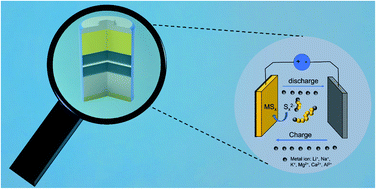

image file: d2ta02217f-p1.tif

Fangyi Shi

Fangyi Shi obtained her bachelor's degree from the Powder Metallurgy Research Institute, Central South University, China, in 2015. Now, she is studying for a PhD degree at the Hong Kong Polytechnic University. Her research interests include metal sulfur batteries and in situ characterization.

image file: d2ta02217f-p2.tif

Shu Ping Lau

Shu Ping Lau is a Chair Professor in the Department of Applied Physics at the Hong Kong Polytechnic University. He obtained his PhD from the University of Wales Swansea. Prof. Lau's current research focuses on nanomaterials and energy materials, particularly the synthesis of 2D materials for optoelectronics, electrocatalysis, and energy storage applications.

image file: d2ta02217f-p3.tif

Zheng-Long Xu

Zheng-Long Xu is an assistant professor in the Department of Industrial and Systems Engineering at The Hong Kong Polytechnic University. He received his BSc in Materials Science and Engineering from Zhejiang University and PhD in Mechanical Engineering from The Hong Kong University of Science and Technology. His research group at PolyU focuses on developing new materials and devices for post-Li battery chemistries (i.e., Li–S, Na-ion, and Ca-ion batteries) and operando characterization technologies (i.e., in situ TEM).


1. Introduction

Rechargeable batteries are expected to be promising systems for dealing with the energy crisis and environmental pollution caused by the combustion of fossil fuels.1 Since their successful launch in the 1990s, lithium-ion batteries (LIBs) have dominated the portable power market and are now penetrating into the green transportation sector via propelling electric vehicles. However, the energy density of LIBs has encountered a bottleneck due to the limited capacity (below 300 mA h g−1) of metal oxide cathodes.1,2 Exploring new battery systems with higher energy densities and lower cost than current LIBs is thus crucial to realize further electrification and carbon neutrality of our modern society. Among the few options, metal–sulfur electrochemistry has been considered promising due to the 2-electron redox reaction per sulfur atom, leading to an exceptionally high theoretical capacity of 1672 mA h g−1 for sulfur cathodes. Owing to the appealing properties of low cost ($150 per ton), eco-friendliness, and abundant supply of sulfur, metal–sulfur batteries (MSBs) are regarded as the next-generation energy storage devices.3,4 Li–S batteries (LSBs) have been intensively investigated since the report on a high-performance CMK-3/sulfur cathode by Nazar's group in 2009.5,6 Recently, propelled by the concerns over Li supply due to its limited and uneven distribution in the Earth’s crust, research on Li-free metal–sulfur (i.e., Na–S, K–S, Mg–S, and Ca–S) batteries has been prospering.5,7 MSB systems share a similar cell configuration and working mechanisms. Their properties in terms of metal abundance, electrochemical properties, volume expansion, and energy density are summarized in Table 1.7,8
Table 1 The comparison of metal–sulfur batteries
Metal–sulfur batteries Discharge products Theoretical voltage (E0/V)8 Volume expansion(ΔV, %) Gravimetric energy density (W h kg−1)8 Volumetric energy density (W h l−1)8 Metal abundance (ppm)7
Li–S Li2S 2.24 80 2612 2955 20
Na–S Na2S 1.85 180 1270 1545 23[thin space (1/6-em)]600
K–S K2S/K2S3 1.88 309 916 952 20[thin space (1/6-em)]900
Mg–S MgS 1.77 24 1685 3221 950
Ca–S CaS 2.47 80 1838 3202 41[thin space (1/6-em)]500
Al–S Al2S3 1.23 40 1319 2981 82[thin space (1/6-em)]300


Unlike the intercalation chemistry of conventional LIB cathodes, metal–sulfur electrochemistry involves complicated phase transitions during cycling. Taking the LSB as an example, the discharging process involves the reduction of solid sulfur (S8) to soluble polysulfides (Li2Sn, 4 ≤ n ≤ 8) and then to solid lithium sulfides (Li2Sn, 1 ≤ n ≤ 2).9 During the following charging process, the lithium sulfides are oxidized to elemental sulfur inversely. The sulfur conversion processes are closely related to the starting materials, working conditions, and electrode structures. The soluble intermediates induce primary problems in LSBs, including the polysulfide shuttle effect, the corrosion of Li metal, the depletion of electrolyte due to the reaction of Li and Sx2−, and the isolation of active materials from conductive hosts.1 The precipitation of insulating lithium sulfides from soluble polysulfides is kinetically sluggish, which deteriorates polysulfide diffusion and causes incomplete sulfur utilization. Other categories of problems of LSBs, such as the insulating nature of sulfur species and the large volume expansion of sulfur upon lithiation (i.e., 80%), induce persistent challenges in conversion electrodes. Consequently, large polarization with poor rate capability and inferior cyclability are often prevalent in LSBs.

To address the above fundamental challenges, tremendous efforts have been devoted to engineering the cathode structure/chemistry and understanding the sulfur conversion mechanisms. In the early stage of LSB research, most studies focused on the development of composite cathodes for improved electrochemical performance,10 such as porous carbon/sulfur and electrocatalyst/sulfur cathodes. In recent years, it has been convergently realized that it is imperative to achieve a better understanding of the reaction mechanisms and effective regulation of this system,11 such as the redox process and the chemical/electrochemical reaction kinetics, to further pave the way towards commercial LSBs. Postmortem analyses of cycled LSBs have been conducted to monitor the chemical/physical states of active materials. However, considering that the polysulfide intermediates are air-sensitive and transient, ex situ characterization studies often fail in presenting the full picture of the electrochemical reaction occurring in LSBs. In contrast, various in situ characterization methods, such as in situ X-ray absorption near-edge structure (XANES) and X-ray diffraction (XRD) characterization, allow real-time detection of the chemical structure evolution in working batteries, enabling the decipherment of the complicated reaction processes without sample contaminants.11–22In situ characterization studies not only provide an in-depth understanding of the redox chemistry in MSBs, but also offer fundamental guidelines for the rational design of sulfur cathodes for achieving improved electrochemical performance.11

Some review papers have summarized the sulfur cathode engineering strategies for LSBs by highlighting the improvement in battery performance. However, several fundamental features from the recent developments of MSBs have rarely been explored, namely (i) the electrochemical and chemical working mechanisms in LSBs using different electrolytes, substrates, and catalysts; (ii) the sulfur conversion electrochemistry in Li-free MSB systems regarding the electrode/electrolyte compatibility, reaction kinetics for high valence cations, and the battery failing mechanisms; and (iii) the state-of-the-art understanding of sulfur conversion mechanics through in situ characterization. Here, this paper primarily discusses these aspects (Fig. 1). The reaction processes and strategies to regulate the sulfur conversion in LSBs will be elaborated by elucidating the correlation among starting materials, electrolytes, electrocatalysts, and reaction processes. Moreover, we discuss the most recent findings in Li-free MSBs, including Na–S, K–S, Mg–S, and Al–S cells with emphasis on surveying reaction processes and battery failure mechanisms. Subsequently, advanced in situ characterization tools to reveal the working mechanisms of MSBs are highlighted. Finally, our perspectives are provided on the remaining issues for future research in MSBs.


image file: d2ta02217f-f1.tif
Fig. 1 Schematic illustration of representative strategies to regulate sulfur conversion in metal–sulfur batteries.

2. Li–S batteries

2.1 Reaction mechanisms in a typical Li–S battery

A typical LSB consists of a Li metal anode, a sulfur-based cathode, and a separator soaked with electrolyte inserted between them. The discharge/charge process is the reversible conversion between S8 and Li2S, involving complex phase transitions as shown in Fig. 2a.23,24 The Li–S conversion process in discharge can be categorized into four regions as listed below:9
image file: d2ta02217f-f2.tif
Fig. 2 (a) Schematic illustration of the reaction process and related reaction products of Li–S batteries. Reproduced with permission: Copyright 2019, Royal Society of Chemistry.11 (b) Photo of liquid sulfur converted to solid sulfur. Reproduced with permission: Copyright 2019, National Academy of Sciences.28 (c) The different Li2S growth mechanisms under high current density and low current density. Reproduced with permission: Copyright 2019, Royal Society of Chemistry.42 (d) Schematic diagram of the activation process of Li2S. Reproduced with permission: Copyright 2012, American Chemistry Society.44

Region I (solid–liquid two-phase conversion, α-sulfur is lithiated to Li2S8):

 
α-S8(s) + 2Li+ → Li2S8(l)(1)

Region II (liquid–liquid single-phase conversion, Li2S8 is lithiated to short-chain polysulfides):

 
Li2S8(l) + 2Li+ → Li2S6(l)(2)
 
Li2S6(l) + 2Li+ → Li2S4(l)(3)

Region III (liquid–solid two-phase conversion, Li2S4 is reduced to Li2S2/Li2S):

 
Li2S4(l) + 2Li+ → Li2S2(s)(4)
 
Li2S4(l) + 2Li+ → Li2S(s)(5)

Region IV (solid–solid single-phase conversion, Li2S2 is lithiated to Li2S):

 
Li2S2(s) + 2Li+ → Li2S(s)(6)

The diffusion of lithium polysulfides (LiPSs) is considered the most challenging issue, hindering the practical implementation of LSBs. In the following, we will give in-depth insights into the electrochemical/chemical reactions involving polysulfides in LSBs.

2.1.1 Redox reaction between sulfur and lithium polysulfides. In Region I, sulfur is converted to long-chain LiPSs (Li2S8) with an apparent discharge plateau at approximately 2.4 V, which contributes 209 mA h g−1 (∼12.5% of the theoretical capacity). During charging, the Li2S8 can be reversibly delithiated to sulfur. Interestingly, in situ XRD studies show that the charging product is the monoclinic β-phase instead of the original orthorhombic α-phase.25 β-sulfur is considered stable normally above 96 °C but it can stably exist in the electrochemical system at room temperature (RT).26 Note that β-sulfur can also be obtained by the melt-diffusion method for sulfur/carbon cathodes.27

Another metastable sulfur species generated through electrochemical redox of polysulfides is liquid sulfur, which was recently observed during polysulfide oxidation on an Au substrate.28 Liquid sulfur was also identified to form on the basal plane of two-dimensional (2D) materials (i.e., graphite, MoS2, and WS2).29 If the 2D material is thick (tens of nanometers), however, solid sulfur nucleates at the edge areas. The liquid sulfur formed on the basal plane would be quickly transformed to solid β-sulfur once it comes in contact with the solid sulfur propagating from the edge areas (Fig. 2b). In addition, the formation of liquid sulfur was reported to be substrate-dependent, where no sulfur droplets were observed on glassy carbon, graphene–nickel foam, and carbon-coated aluminum.28,30 Compared to solid sulfur, liquid sulfur resulted in superior reaction kinetics and area capacities due to its unique mobility and reshaping capability.29 Liquid sulfur also creates an opportunity to allow the conversion between sulfur and LiPSs to change from a solid/liquid reaction to a liquid/liquid reaction, which shows promise to design flow batteries and fast-charging batteries. However, studies on liquid sulfur chemistry are still in infancy. Several critical questions remain to be explored, namely (i) liquid sulfur is preserved much below sulfur's melting point (115 °C).28 The origin of this thermodynamically unstable phase is unclear; (ii) liquid sulfur was virtually observed in flooded-electrolyte LSBs, and the scenarios in high sulfur loading (>7 mg cm−2) and lean-electrolyte (<4 μL mg−1) conditions have not been explored; (iii) liquid sulfur is metastable and readily dissolves in electrolyte. Preserving liquid sulfur for reversible liquid LSBs is also challenging.

2.1.2 Redox reaction between long-chain and short-chain polysulfides. In Region II, long-chain Li2S8 is further reduced to short-chain Li2Sx (4 < x ≤ 6) showing a slope from 2.4 to 2.1 V.31 At the end of this stage, the viscosity of the electrolyte reaches the vertex arising from the major product S42−.32 This step associated with the liquid–liquid single-phase reaction is believed to exhibit fast reaction kinetics. The LiPSs’ status is highly subject to electrolyte properties, such as the solvent species, the solubility of LiPSs, and salt concentration.33 The electrolyte structure can also regulate the reaction pathway in Region II. For example, the stable S3˙ radical was generated through S62− dissociation in a high-donor-number (DN) solvent electrolyte (i.e., dimethyl sulfoxide, DMSO, DNDMSO = 29.8), whereas a low-DN solvent electrolyte (i.e., dimethoxyethane/dioxolane, DME/DOL, DNDOL = 18) mainly involves S42− formation.32

Apart from the intrinsic LiPS chemistry, the extrinsic behavior of LiPSs (e.g., diffusion, dissolution, and shuttling) can induce both favorable and unfavorable impacts on LSBs. The electronically insulating LiPSs are soluble in ether-based electrolytes. During discharging, they are susceptible to losing contact with the cathode and gradually diffuse to the anode side driven by the concentration gradient or/and electric field, resulting in the corrosion of Li metal and irreversible loss of active materials. During charging, the short-chain LiPSs deposited on Li metal would be re-oxidized and diffuse back to the cathode, leading to low coulombic efficiency and severe self-discharge. Therefore, the shuttling of LiPSs back and forth between electrodes, the so-called shuttling effect, results in amplified electrolyte depletion, capacity degradation, and battery failure.34 Alternatively, LiPSs also play favorable roles in improving the reaction kinetics in LSBs. Upon discharging, LiPSs are able to react with insulating sulfur via chemical disproportionation (e.g., S8 + Li2S4 → Li2S6), thus dragging the insulating sulfur into the electrolyte for further conversion reaction. A similar effect also occurs in the charging process, where liquid LiPSs catalyze the oxidation of Li2S to overcome its dramatically high activation energy barrier.34 In short, soluble LiPS is a double-edged sword that is both harmful and beneficial to the Li–S electrochemistry. How to rationally manipulate the LiPS behavior to reinforce the advantageous properties while suppressing the negative effect is a challenging and rewarding direction for future LSB study.

2.1.3 Redox reaction between short-chain LiPSs and Li2S. The further reduction from soluble Li2S4 to solid Li2S/Li2S2 (Region III) is kinetically sluggish, and the solid–solid conversion kinetics between Li2S and Li2S2 in Region IV is slower. A potential dip is usually observed at the beginning of Region III, due to the centripetal polarization from highly viscous Li2S4 (ref. 35) and the overpotential to drive solid phase nucleation.20 Regions III and IV contribute 1254 mA h g−1 (i.e., 75% of the theoretical capacity), and thus their reaction kinetics, depth, and reversibility play critical roles in the battery performance.

The electrochemical deposition of Li2S2/Li2S from soluble polysulfides involves solid nucleation and growth behavior. Chiang et al.36 demonstrated that the nucleation of lithium sulfides on conductive substrates occurred along the three-phase boundary between solid lithium sulfide precipitates, the conductive substrate, and the polysulfide solution. The deposition behavior is associated with the host surface chemistry,37 separators,38 and electrolyte structures.39 For example, three-dimensional (3D) Li2S precipitation was achieved by decorating carbon hosts with black phosphorus quantum dot (BPQD) catalysts.40 High-DN solvent-based electrolytes can ameliorate the LiPS solubility to promote 3D Li2S deposition.41 In addition, current densities also influenced the deposition morphologies of Li2S2/Li2S.42 It was reported that the precipitation of Li2S2/Li2S at a high current density (360 μA cm−2) followed a surface deposition route but a solution-mediated growth model at a low current density (9 μA cm−2, Fig. 2c). As a result, Li2S would form thin and continuous films with large nucleation density at high current density, and in contrast, large and discrete Li2S particles were observed at low deposition current.42,43 Given the insulating nature of Li2S/Li2S2, the in-solution growth model is more favorable with larger precipitate volumes and higher sulfur utilization than the surface-deposition counterpart.

During the charging process, Li2S2/Li2S would be dissolved and converted to LiPSs. Similar to its precipitation mechanism, dissolution of Li2S2/Li2S only occurs at the three-phase boundary among the Li2S/Li2S2, host, and electrolyte with electronic and ionic conductivities.44 At the beginning of the charging curve (Fig. 2a), a potential hill can be clearly observed, representing an extra driving force to activate the Li2S2/Li2S oxidation.10,44 The potential hill is related to several key parameters, namely (i) the phase and crystallinity of Li2S/Li2S2, (ii) the electronic/ionic conductivity of the substrate, and (iii) the presence of mediators, such as LiPSs. Compared to highly crystalline Li2S/Li2S2, oxidation of the amorphous phase was reported to be easier without residuals after full charging.45 Because of the improved conductivity of few-layer graphene wrapped Li2S, the Li2S@graphene nanocapsules exhibited notable area capacities of 8.1 mA h cm−2 at a high loading of 10 mg cm−2.46 When micronized Li2S is directly used as the cathode, it required an activation voltage of over 3.5 V, and the activation process is displayed in Fig. 2d.47 After the first cycle, the overpotential for charging in the later cycles became much smaller. It is attributed to the presence of LiPSs to mediate the Li2S dissolution.44 Moreover, Li2S–metal/carbon composites,47,48 redox mediators in electrolytes,49,50 and electrocatalysts51,52 have also been demonstrated to be efficient in alleviating the Li2S2/Li2S activation barrier for improved cycling capacities.

2.1.4 Chemical reaction among polysulfides. Apart from electrochemical reactions, chemical reactions among LiPSs also occur in LSBs and contribute capacities. In DMSO and DME/DOL electrolytes, for example, the (electro)chemical reactions can be depicted as follows:53
 
S8 + 2e → S82− electrochemical(7)
 
S84− → 2S42− disproportionation(8)
 
S82− → S62− + 1/4S8 (in DMSO) disproportionation(9)
 
S62− ↔ S3˙ (in DMSO) disproportionation(10)
 
2S42− → 6/7 S82− + 8/7 S12− disproportionation(11)

Taking the electrochemical reaction into consideration as well, we can find that the reaction process in LSBs is very complex. In addition, different solvents would induce different reaction pathways (both chemical and electrochemical reactions). For example, the disproportionation reactions in eqn (9) and (10) are prone to happen in electron-pair donor solvents with high dielectric constant (i.e., DMSO). Some disproportionation reactions are disadvantageous to battery cycling. The solid products generated in the disproportionation reactions of LiPSs (eqn (9) and (11)) would increase the interfacial resistance by passivating electrode surfaces.54 The disproportionation between LiPSs may also induce LiPS accumulation and diffusion.55 Therefore, understanding and regulating the chemical reactions are of significance to draw a whole picture of sulfur conversion chemistry and guide the Li2S or S8 activation through selected disproportionation routes.56

2.2 Li–S conversion chemistry in other sulfur-containing materials

It is clearly observed from the above content that the formation and dissolution of LiPSs are inevitable and disruptive in LSBs. Apart from elaborating LiPS-retaining strategies,57 avoiding and suppressing the existence of LiPSs in the sulfur conversion process can also improve the LSB cyclability. Some sulfur-containing compounds, including small sulfur molecules, organosulfur polymers, and metal sulfides, can meet this requirement.
2.2.1 Small sulfur allotropes. Confinement of small sulfur allotropes S2–4 in microporous carbon (pore size ∼0.5 nm, Fig. 3a) is a successful example to avoid LiPS diffusion in bulk electrolytes through a solid–solid conversion.58,59 The narrow pores can successfully prevent the direct contact between sulfur molecules and electrolytes by desolvating the solvated-Li before solid Li diffusion in the carbon host (Fig. 3b).58 Therefore, the electrode can be cycled in both ether-based and carbonate-based electrolytes (Fig. 3c). The smaller sulfur molecules showed excellent cycling stability with capacities above 600 mA h g−1 after 500 cycles at 400 mA g−1.
image file: d2ta02217f-f3.tif
Fig. 3 (a) Sulfur confined by CNTs with 0.5 nm-sized pores. Reproduced with permission: Copyright 2012, American Chemistry Society.59 (b) Exclusion of carbonate electrolyte molecules from 0.46 nm micropores. (c) Potential curves of S2–4 in a carbonate-based electrolyte. Reproduced with permission: Copyright 2014, Wiley-VCH.58 (d) The change of relative amount of S, long-chain Li2Sy, short-chain Li2Sy, and Li2S during the discharge process when using the ultra-microporous carbon/S as the cathode in carbonate solvent-based electrolytes. Reproduced with permission: Copyright 2018, Electrochemical Society.61 (e) The proposed redox reaction process of alucone C–S cathodes in carbonate solvent-based electrolytes. Reproduced with permission: Copyright 2018, Nature Reseach.62

Despite the extended cycle life of LSBs, this approach faces several fundamental challenges. First, the charge-transfer kinetics depend on the electronically conductive carbon, resulting in S2–4/microporous carbon with higher resistance than the ‘open-type’ S8/porous carbon due to the large energy barriers for Li desolvation, solid Li-ion diffusion, and solid–solid Li–S conversion processes. Second, due to the limited space, the sulfur content is restricted to less than 50%,57,58 which is far from sufficient to meet practically high energy LSBs demanding sulfur loadings of above 70 wt% and 7 mg cm−2. Third, the conditions to realize solid–solid reactions are ambiguous. It is argued that solid electrolyte interface (SEI) layers formed on the surface of the sulfur/mesoporous carbon cathode would also trigger the solid–solid reaction,60 disrupting the compulsory micropores. Fourth, the reduction mechanism of S2–4 in microporous carbon is under debate. Some papers proposed that S2–4 is lithiated to long-chain LiPSs, short-chain LiPSs, and finally Li2S, similar to the lithiation of S8, through operando XAS characterization (Fig. 3d).61 Others argued that the redox process between S2–4 and Li only involves sulfur and Li2S without any intermediates, the same as the alucone C–S cathodes in carbonate-based electrolytes (Fig. 3e).62 Therefore, both the electrochemical performance and fundamental understanding of reaction mechanisms of small sulfur allotropes need investigation in future studies.

2.2.2 Organosulfur polymers. Organosulfur polymers consisting of organic groups and sulfur chains have also been widely investigated as promising alternatives to S8 to solve the problems of LiPSs.63 In organosulfur compounds, sulfur atoms are covalently bonded with organic frameworks. This structure can inherently entrap sulfur species, particularly LiPSs, and avoid agglomeration or re-displacement of sulfur during cycling, and thus the sulfur utilization is improved, and the shuttle effect is suppressed by molecular immobilization.63 The electrochemical process of organosulfur compounds can be classified into three types as shown in Fig. 4a.
image file: d2ta02217f-f4.tif
Fig. 4 (a) The different electrochemical processes of different organosulfur compounds.63 Reproduced with permission: Copyright 2020, Royal Society of Chemistry. (b) The general reaction equation of the overall Li/SPAN reaction. Reproduced with permission: Copyright 2014, Multidisciplinary Digital Publishing Institute.71 (c) The photos of a series of liquid phenyl polysulfides. Reproduced with permission: Copyright 2018, American Chemistry Society.74 (d) Schematic illustration of the CEI formed on CMK-3/Se and CMK-3/S cathodes in a carbonate-based electrolyte. Reproduced with permission: Copyright 2021, Wiley-VCH.76

The first class of organosulfur undergoes the solid–liquid–solid conversion path, resembling the electrochemical process of S8.63 A representative example is the poly(sulfur-random-1,3-diisopropenylbenzene) (S-DIB) which is synthesized by heating polymeric sulfur and DIB together.64 The S-DIB displayed an S8-like discharge/charge potential profile with two typical reaction plateaus. Due to the chemical bonding of the copolymers, pristine S-DIB exhibited a reasonable cycle life of 100 cycles at 0.1C. Consequently, the S-DIB@CNT cathode was prepared with enhanced electrical and ionic conductivities,65 and it presented a high initial capacity of 1300 mA h g−1 and a cycling capacity of 880 mA h g−1 at 1C. Inspired by the S-DIB structure, organosulfur polymers containing conjunction units of benzene rings, thiophene, and thiazine have also been exploited for improved battery performance.66 Zhou et al.67 prepared a linear copolymer containing thiokol rubber-like poly(methylene tetrasulfide) to stabilize LiPSs by forming strong chemical bonds (e.g., Li–S2–CH2–S–Li or Li–S–CH2CH2–S–Li). For this kind of organosulfur compound, the future study should pay attention to two key parameters, namely (i) the length of the sulfur chain and the organic unit, which determines the physicochemical stability and the sulfur content; (ii) the bandgap of polymers, which governs their conductivity and rate capability in LSBs.

The second class of organosulfur polymers only undergoes solid–solid reaction without the LiPS formation.68,69 Sulfurized polyacrylonitrile (SPAN) is one of the most attractive examples with remarkable electrochemical cycling stability in carbonate-based electrolytes.70 SPAN can be simply produced by heating mixtures of sulfur and acrylonitrile, which is polymerized and sulfurized into a conjugated structure as shown in Fig. 4b. During lithiation/delithiation, it was proposed that SPAN underwent a solid-phase conversion where the C–S bonds were reversibly broken and reformed.71 It is noted that there are two models to explain the sulfur storage in SPAN. One is sulfur chains act as bridges to connect the conjugated PAN skeleton, another is the sulfur is siding chains on the conjugated PAN.72 Although SPAN can avoid the shuttle effect, this kind of material also has problems, such as low sulfur loading (∼40%), poor conductivity, and sluggish redox kinetics. In order to improve the conductivity and reaction kinetics, Wang et al.73 reported a freestanding fibrous SPAN/CNT cathode. After activation, the cathode could maintain a reversible capacity of 1400 mA h g−1 over 200 cycles at 200 mA g−1, and 1180 mA h g−1 over 800 cycles at 800 mA g−1. Chen et al.72 reported a Se-doped SPAN (SexSPAN) cycling in carbonate-based and ether-based electrolytes. Interestingly, different from the solid–solid phase transition of pure SPAN in ether electrolytes,73 a solid–liquid–solid transition path was detected for SexSPAN with high rate capabilities. This study suggests that the sulfur conversion processes and electrochemical performance of SPAN are tunable by heteroatom doping. In addition to SPAN, sulfur-rich organosulfur materials with short sulfur-chains (S2–4) have also been reported to show LiPS-free cycling performance. Shadike et al.68 incorporated the 2,3,4,6,8,9,10,12-octathia biscyclopenta[b,c]-5,11-anthraquinone-1,7-dithione (TPQD) skeleton with high capacity and soluble 1-4-benzoquinone (BQ) into TPQD-BQ organosulfides. The organic cathode delivered high capacities, great rate capability and stable cycling performance in LSBs. Zhang et al.69 synthesized disulfide polymer (DSP) and trisulfide polymer (TSP) cathode materials. The electrolyte in optical cells containing TSP remained colorless during cycling, manifesting no LiPS formation.

As for the third type of organosulfur, they are usually small molecules in the liquid phase, undergoing a liquid–solid transformation in LSBs.63 Bhargav et al.74 synthesized phenyl polysulfides C6H5SxC6H5 (4 ≤ x ≤ 6) as a liquid cathode, as shown in Fig. 4c. During lithiation, the phenyl polysulfides were reduced to solid Li2S and phenyl-SLi. Due to the liquid–solid conversion, the cell delivered great performance with a lean electrolyte, for example, an area capacity of 7.6 mA h cm−2 was retained after 500 cycles at 1C under an E/S ratio of 3 μl mg−1.

2.2.3 Inorganic sulfur compounds. When some sulfur-containing inorganic compounds exhibit working voltages close to 2 V vs. Li/Li+ and sulfur content of >40 wt%, they are regarded as sulfur-equivalent cathodes in LSBs.75 Ye et al.75 reported an amorphous MoS3 as a LSB cathode. MoS3 was proposed to have a chain-like structure consisting of Mo bridged by sulfide and disulfide ligands. The operando XAS spectrum was obtained to learn the reaction mechanisms of the MoS3 cathode. It shows that both the sulfur and Mo were reduced during lithiation, but they did not form Li2S or polysulfides. The Li-ions were supposed to accumulate at the bridge sites between two adjacent sulfur atoms. No disintegration of sulfur or MoS3 took place during cycling. As a result, the MoS3 cathode delivered a high capacity of ∼383 mA h g−1 after 1000 cycles at 0.45 A g−1. Selenium (Se), an element in the same group as oxygen and sulfur, has also been compounded with S to form SexSy as sulfur-equivalent cathodes in LSBs. It was found that the Se in CMK-3/SexSy could induce the formation of a thin cathode electrolyte interface (CEI) layer on cathodes in carbonate electrolytes.76 As shown in Fig. 4d, electrolyte molecules would be blocked by the CEI to attack polysulfides or polyselenides encapsulated within the carbon host. The thickness of the CEI layer signified a positive relationship with the Se content. Thus, optimal CMK-3/Se5S3 with a desirably thick CEI achieved a remarkable capacity retention of 609 mA h g−1 after 300 cycles at 1 A g−1.77

Overall, in the past decade, tremendous progress has been achieved in understanding the fundamental mechanisms of sulfur conversion chemistry in LSBs. Inherently, the Li–S conversion behavior is determined by the stage of reaction, the nature of starting materials, and the intermediate chemical species. It is also observed that the complicated reaction processes involve both favorable (i.e., disproportionation reaction to dissolve insulating sulfur or Li2S) and unfavorable (i.e., sluggish conversion of polysulfides) steps. To improve the electrochemical performance, effective strategies have been developed to regulate the sulfur conversion processes which are interpreted in the following section.

2.3 Regulating the sulfur conversion chemistry

2.3.1 Current collector engineering. The current collector functions as the bridge between electric circuits and electrode materials.78 It also has a great impact on the electrochemical behavior of LSBs. In general, the sulfur cathode is fabricated by casting a mixture of active materials, binders, and conductive carbon black on Al foil.79 Other 2D films or foil materials such as Ni, Pt, Cu, and carbon cloth (CC) have also been investigated as potential current collectors. It is found that Cu and Ni are unstable as they are corroded by polysulfides or components in the electrolytes.80 LSBs with CC and graphene film current collectors exhibit better electrochemical performance than the Al counterpart,81 attributable to their larger surface area and better anti-corrosion capability.82

3D current collectors have also been studied as promising alternatives to their 2D counterparts in view of their interconnected conductive networks, large surface area, and abundant ion diffusion channels, all of which are important for high sulfur loading and fast reaction kinetics.83 For example, 3D carbon nanotube (CNT) films have been prepared as current collectors for LSBs. Compared with 2D Al foil and graphene current collectors, LSBs with 3D CNT current collectors displayed much superior electrochemical performance (Fig. 5a) with a high cycling ability (95 cycles with 0.029% decay rate) under high sulfur loadings.82 Other carbon materials have also been built into 3D current collectors, such as graphene foam (GF)84 and 3D melamine formaldehyde-based carbon foam (MFC).85 However, the nonpolar carbon cannot entrap LiPSs to suppress the shuttle effect in LSBs.


image file: d2ta02217f-f5.tif
Fig. 5 (a) Comparison of 2D Al current collectors, 2D graphene foam current collectors, and 3D CNT current collectors. Reproduced with permission: Copyright 2016, Wiley-VCH.82 (b) Schematic illustration of the sulfur species evolution on Ni, C, and Al substrates during charging and discharging processes. Reproduced with permission: Copyright 2020, The American Association for the Advancement of Science.30 (c) The comparison of electrocatalytic electrodes and absorption electrodes. Reproduced with permission: Copyright 2018, Elsevier.96 (d) Schematic showing the promotion of Li2S dissolution to LiPSs on metal sulfides. Reproduced with permission: Copyright 2017, National Academy of Sciences.52

To regulate the entrapment and catalytic capability of current collectors for high-performance LSBs, surface modifications have been conducted for light and 3D carbon current collectors.86 For example, we have prepared MoS2/carbon nanofiber (CNF) films by electrospinning.37 Then, a catholyte containing polysulfides and electrolyte was dropped on MoS2/CNF films as cathodes. Owing to the 1T MoS2 catalyst and the 3D conductive carbon network, MoS2/CNF/Li2S6 delivered a remarkable capacity retention of 9.3 mA h cm−2 after 300 cycles with an exceptionally high sulfur loading of 12.9 mg cm−2 and a lean electrolyte loading of 4.6 μl mg−1. A Mo2C decorated N-doped CNF current collector has also been proved to effectively mitigate the shuttle effect by taking advantage of the strong LiPS affinity for MoC2.87 A pyrrole polymer with strong chemical bonding with LiPSs was introduced into GF current collectors. The pyrrole GF/S cathode displayed a great cycling ability (over 100 cycles with 81% capacity retention) and high specific capacity (1220 mA h g−1).88 In addition to polysulfide entrapment, functional current collectors have also been designed to regulate the LiPS conversion kinetics and the Li2S deposition behavior. For example, the Co,N-CNTs-CNS (carbon nanosheet)/CFC (carbon fiber cloth) current collector induced a 3D deposition of Li2S.89 Compared to the routine 2D growth of Li2S, the 3D structure of Li2S enables higher LiPS utilization and thus effectively suppresses their diffusion to bulk electrolytes.

Apart from the discharging (or lithiation) process, the current collectors also play a non-negligible role in the charging process in LSBs. Using in situ optical microscopy, Zhou et al.30 observed distinct sulfur growth behavior on Al, C, and Ni current collectors. They found that solid sulfur emerged on the carbon surface, while liquid sulfur droplets grew on Ni substrates (Fig. 5b). The different sulfur growth behaviors were attributed to different binding energies of S8 with Ni, C, or Al substrates through DFT calculations. The moderate interaction between Ni and S8 (−1.4 eV vs. −0.93 eV for S8 on C, −5.44 eV for S8 on Al) was the precondition for sulfur droplet formation. As aforementioned, liquid sulfur enables high mobility and fast phase transition, thus accelerating the reaction kinetics in LSBs. Consequently, a lightweight, 3D Ni-coated melamine current collector was synthesized for high-rate and long-life LSBs. Similarly, two-dimensional materials (i.e., MoS2 and graphene)29 or deposited Au layer90 current collectors have also been reported to generate the liquid sulfur product with high area capacities in on-chip micro-LSBs.

Overall, the nature of current collectors is important in influencing the electrochemical behavior in both discharging and charging processes. Self-supporting and 3D current collectors are desirable as high-loading sulfur hosts. Functional materials on 3D networks are also recommended to accelerate the Li–S redox kinetics. Research on the impact of current collectors on the charging process is still in the initial stage. More efforts are expected to unveil the reasons for current collectors regulating the whole charging/discharging cycle in LSBs.

2.3.2 Electrocatalyst design. One of the fundamental challenges in sulfur utilization is the insulating nature of sulfur species. Therefore, tremendous efforts have been made to design carbon nanomaterials as highly conductive hosts for sulfur particles. Although improvement in electrochemical performance has been witnessed by compositing sulfur and conductive carbon, the long-term and high-rate capacities of such sulfur/carbon cathodes are often jeopardized due to the eventual dissolution of polysulfides caused by the weak interaction between polar polysulfides and nonpolar carbon. In this respect, studies on electrocatalysts, enabling chemical trapping and catalytic conversion of polysulfides, have recently been carried out and they demonstrated their effectiveness in regulating sulfur conversion chemistry for high-performance LSBs. According to their functions and the report timeline, electrocatalysts can be divided into four categories, namely chemical adsorbers, adsorption–diffusion–conversion catalysts, bi-directional catalysts, and selective catalysts.

In the early stage of catalyst study for LSBs, it was believed that polar materials, such as N-doped carbon, metal oxides, and dichalcogenides, can form polar–polar interactions or Lewis acid-based bonding with LiPSs, thus preventing their diffusion.91 One of the typical examples is mesoporous silica, which was added in the CMK-3/S composite as a sulfur reservoir to trap and store the soluble polysulfides during cycling, thus leading to better cycling stability than that of pure CMK-3/S.92 Similarly, TiO2, NiO and CoO93–95 have also been investigated to block the LiPS diffusion. However, it was quickly found that improvement in battery performance using these materials was limited because the entrapped LiPSs cannot be effectively converted to Li2S due to the poor electronic conductivities of these catalysts (Fig. 5c).96

To improve the sulfur usage rate and suppress LiPS diffusion, conductive catalysts were then reported to supply a consecutive LiPS adsorption–diffusion–conversion pathway.97 Taking black phosphorus (BP) as an example, it possesses good bulk conductivity, a fast Li-ion diffusion constant, and high binding energies with polysulfides. Few-layered BP sheets were therefore adopted in separators98 or current collectors99 to suppress the diffusion of LiPSs. Through DFT calculations, we discovered that BP presented edge-selective catalytic properties, where the zig–zag terminated BP resulted in stronger binding energies with polysulfides at the edges than at terrace sites.40 This finding suggests that we can largely increase the catalytic properties by downsizing BP flakes into BPQDs. The electrochemical performance revealed that BPQDs have a robust catalytic capability, and the porous carbon/S/BPQD cathodes presented rapid reaction kinetics and no shuttling of polysulfides. Another representative electrocatalyst worth mentioning is the TiO2/TiN heterostructure enabling smooth trapping–diffusion–conversion of polysulfides towards stable LSBs.100 The heterostructure combined the merits of highly adsorptive TiO2 (for trapping) and conductive TiN (for conversion), thus providing a complete strategy to synchronously realize LiPS adsorption and conversion. Other polar materials (i.e., metal oxides, metal sulfides, and metal nitrides)101 and single-atom catalysts (i.e., Co–N–C and Fe–N–C)102 have also been developed to enhance the reduction of LiPSs into Li2S.

The catalytic oxidation of Li2S during charging is equally important to obtain highly reversible LSBs. Zhou et al.52 illustrated that VS2-, TiS2- and CoS2-modified cathodes promoted the dissolution and conversion of Li2S to LiPSs (Fig. 5d). Owing to the high binding energy between the isolated Li-ions and sulfur in sulfides, the metal sulfides would lower the energy barrier for the oxidation of Li2S to improve the Li2S decomposition kinetics. Inspired by the outstanding catalytic capability of Pt and Ni in fuel cells, noble metals were also investigated to reduce the energy barrier for the oxidation process of lithium sulfides to soluble LiPSs.103 However, most of the synthesized catalysts function in one direction (reduction or oxidation) because of their intrinsic electron donor or acceptor nature, which is unsatisfactory to accelerate the discharge/charge reactions in LSBs simultaneously. To mitigate this challenge, a TiO2–Ni3N2 heterostructure104 was prepared as a bidirectional catalyst. Typically, TiO2 traps while Ni3N2 catalytically reduces LiPSs during discharging, and both TiO2 and Ni3N2 catalyze the Li2S dissolution during charging. The sulfur cathode containing TiO2–Ni3N2 delivered a low capacity decay rate of 0.038% per cycle over 900 cycles, accordingly.

When we recall the sulfur conversion processes in Section 2.1, it is found that the transformation of polysulfides from high order to low order is generally fast, but the kinetics of further reducing Li2S4 to solid Li2S2/Li2S is slow. The kinetics mismatch would lead to saturation of polysulfides on the surface of catalysts and stall further LiPS adsorption. Therefore, precisely regulating sulfur conversion to ensure compatible LiPS formation and consumption speeds becomes another challenging issue for electrocatalyst design. Hua et al.105 reported an In2O3 catalyst that would selectively decelerate the conversion from S to LiPSs, while accelerating the reduction of Li2S4 to Li2S. This catalysis could alleviate the accumulation of LiPSs around the cathode to suppress the shuttle effect, leading to enhanced electrochemical performance. The dynamically changing catalytic mechanism was unveiled by in situ Raman analysis. It showed that In2O3 was reversibly converted to LiInS2 to accelerate LiPS deposition to insoluble Li2S during discharging, while LiInS2 was converted back to In2O3 for activating Li2S oxidation during the following charging process. Similarly, Li et al.106 reported a stepwise polysulfide conversion catalyst, defect-rich Co3O4/TiO2 (denoted as p-Co3O4/n-TiO2-HPs). The Co3O4 physicochemically immobilized pristine sulfur and controlled the reduction of S8 to Li2S4, while the TiO2 dots facilitated the diffusion and reduction of Li2S4 to solid Li2S, which is attributed to the p-Co3O4/n-TiO2 built-in electric field. As a result, the precisely regulated LSB delivered an exceptionally high rate capability at 10C with a low capacity decay rate of 0.07% per cycle over 500 cycles.

In summary, different kinds of materials display specific functions to catalyze the redox reactions of LSBs. Heterostructures signify the most promising strategy, which can combine specific functions of different catalysts into one structure, thus precisely regulating the sulfur conversion dynamics and kinetics for complex Li–S systems. Despite the encouraging progress, the investigations on electrochemical catalysts are still in the very beginning stage with a large room to explore. Several directions are suggested, namely (i) understanding and in situ evaluation of the structural evolution of catalysts during cycling, (ii) reducing the content of electrochemically inert catalysts in LSBs, and (iii) understanding the catalytic mechanisms under extreme conditions, such as high sulfur loading, lean electrolyte, and extreme working temperatures.

2.3.3 Electrolyte engineering. The electrolyte chemistry indicates considerable abilities to regulate the sulfur conversion behavior, thus critically affecting the energy density and cycling performance of LSBs. 1 M LiTFSI in equal volume DME and DOL is the most common electrolyte formula for LSBs. The DME/DOL solvent presents limited LiPS dissolvability, enabling ready saturation of short-chain polysulfides, particularly under lean electrolyte conditions.107,108 To mitigate this issue, Cheng et al.109 designed a novel ε-caprolactam/acetamide-based eutectic-solvent electrolyte, which had the ability to completely dissolve Li2S8 and Li2S (Fig. 6a). The phase transformation from ‘solid–liquid–solid’ in DME/DOL was turned to ‘solid–liquid’ in this new electrolyte. Therefore, the core problems of voltage polarization and Li2S activation can be settled. Dominko et al.61 studied the sulfur reduction processes in ether-based electrolytes (TEGDME[thin space (1/6-em)]:[thin space (1/6-em)]DOL with high LiPS solubility), fluorinated ether-based electrolytes (TTFE[thin space (1/6-em)]:[thin space (1/6-em)]DOL with low LiPS solubility), and carbonate-based electrolytes (EC[thin space (1/6-em)]:[thin space (1/6-em)]DMC, with S2–4/microporous carbon cathode, no LiPS formation) by XAS characterization. In all three cases, the sulfur reduction went through the same processes, sulfur → long-chain LiPSs → short-chain LiPSs → Li2S/Li2S2, with a difference in the type of polysulfides formed in the corresponding steps of discharge. When the sulfur was converted to LiPSs, the potential of the discharge plateau in the ether-based electrolyte was higher than that in the fluorinated ether-based electrolyte, indicating a positive relationship between LiPS solubility in the electrolyte and overpotential for discharging. The discharging product in the carbonate-based electrolyte was a mixture of Li2S and Li2S2 (molar ratio of 2[thin space (1/6-em)]:[thin space (1/6-em)]1), which is different from the end-product of Li2S in coexistence with polysulfides in ether-based electrolytes.
image file: d2ta02217f-f6.tif
Fig. 6 (a) Li2S, Li2S2, Li2S4, Li2S6, and Li2S8 dissolved in an ε-caprolactam/acetamide based eutectic solvent electrolyte. Reproduced with permission: Copyright 2019, Wiley-VCH.109 (b) Sulfur reaction pathways in DOL[thin space (1/6-em)]:[thin space (1/6-em)]DME and DMSO. Reproduced with permission: Copyright 2016, American Chemical Society.32 (c) The relationship between solvent properties (i.e., donicity, Li2S solubility, and mobility) and battery performance. Reproduced with permission: Copyright 2019, Wiley-VCH.112

The solvents with different DN can affect the Li–S redox pathways, intermediate species, and Li2S deposition morphologies.32 As shown in Fig. 6b, in the high-DN solvent electrolyte (i.e., DMSO, DN = 29.8), Li–S reactions undergo multiple electrochemical and chemical reactions involving S82−, S62−, S42−, and S3˙ where S3˙ is the most stable intermediate to convert to solid lithium sulfides. However, in the low-DN-solvent electrolyte (i.e., DOL[thin space (1/6-em)]:[thin space (1/6-em)]DME), S42− was the main intermediate before Li2S2/Li2S deposition. It is clear that the presence of S3˙ is solvent-dependent. The reaction pathway involving the S3˙ radical was favorable to promote sulfur utilization by exacerbating dissociations to allow full conversion of sulfur and lithium sulfides.110 High-DN-solvent DMSO is favourable for S3˙ formation, but it presents poor anodic stability against metallic Li. Note that the high-DN solvent always presents a high dielectric constant (ε).32 Tetramethylurea (TMU) with better compatibility with Li metal and comparably high ε (ε = 23.6) was investigated to form active S3˙ radicals.107 Large amounts of S3˙ in the DOL/TMU co-solvent were confirmed by Raman characterization. The presence of S3˙ radicals enabled the efficient conversion of Li2S in TMU during charging and the deposition of thick and porous Li2S during discharging, whereas an appreciable performance was not observed in the DOL/DME electrolyte. The pouch cells using the TMU electrolyte delivered a remarkable capacity of 1524 mA h g−1 and a high energy density of 324 W h kg−1.

Although high DN solvents can facilitate the rapid and complete conversion of sulfur and Li2S by increasing polysulfide dissolution, other electrolyte properties such as ionic conductivity, viscosity, and electrode wettability also govern the Li2S deposition behavior. Pan et al.111 explored Li2S deposition in three representative solvents, including tetramethylene sulfone (TMS) with low-DN, DOL[thin space (1/6-em)]:[thin space (1/6-em)]DME with mid-DN, and DMSO with high-DN. SEM images showed that the deposited Li2S on the carbon nanofiber surface was in the form of thin films in TMS, micro-sized “flower-like” sheets in DOL[thin space (1/6-em)]:[thin space (1/6-em)]DME, and small nanoparticles in DMSO. Although DMSO indicated 3D growth of Li2S, the relatively small Li+ diffusion coefficient restricted the growth of small nucleation seeds into 3D Li2S, causing inferior sulfur utilization and cycling capacities to those in the DOL[thin space (1/6-em)]:[thin space (1/6-em)]DME-based electrolyte. Li et al.112 studied the effects of DN (high DN induces Li2S 3D deposition), dielectric constant (high ε leads to high Li2S solubility) and viscosity (high η leads to low polysulfide mobility and poor wettability) on the electrochemical deposition behavior of Li2S (Fig. 6c). Among ether-based solvents, DME (G1) with low DN and Li2S solubility displayed fast 2D lattice growth of Li2S films and passivated the electrode surface impeding the further reduction reaction. The low Li2S solubility and high viscosity of the TEGDME (G4) electrolyte induced insufficient sulfur utilization as well. In the high DN electrolyte group, the sulfur cathode displayed the largest discharge capacity of 1100 mA h g−1 in the DMA solvent due to the high Li2S solubility, suitable DN and high ionic mobility. The battery with the highest-DN DMSO electrolyte displayed the smallest discharging capacity of 220 mA h g−1 because of the ultralow Li2S solubility.

The polysulfide dissociation behavior can be tuned using the lithium salt species and concentration in electrolytes. Chu et al.113 investigated how the salt anions with different DN could tailor the Li2S deposition behavior. Lithium bromide (LiBr), lithium triflate (LiTf), and lithium bistriflimide (LiTFSI) with DN = 33.7, 16.9, and 5.4, respectively, were dissolved in DOL/DME as electrolytes. The battery with LiBr and LiTf-based electrolytes exhibited superior reversible capacities to that of LiTFSI electrolytes (1535, 1214 vs. 400 mA h g−1) due to the high efficiency of Li2S deposition and decomposition. 3D Li2S micron particles were deposited on CC in LiTf and LiBr electrolytes, while a 2D passivating film was detected in LiTFSI electrolyte. The 3D deposition was related to the precipitated Li2S possessing strong adsorption to S2−. The free S2− anions preferred to deposit on the surface of precipitated Li2S seeds, resulting in a 3D growth of Li2S under the action of high DN anions to promote free S2− formation. Suo et al.114 reported a solvent-in-salt electrolyte with high LiTFSI concentration in DOL[thin space (1/6-em)]:[thin space (1/6-em)]DME. In the 7 M highly concentrated electrolyte, few free solvent molecules significantly limited the dissolution and diffusion of LiPSs. LSBs with solvent-in-salt electrolytes delivered an initial capacity of 1041 mA h g−1 and 74% capacity retention after 100 cycles. However, high salt concentration causes problems of high cost, low ionic conductivity, and high viscosity.

Adding electrolyte additives to diluent electrolytes is another promising way to regulate LiPS dissociation in LSBs. ZrO(NO3)2 with strong negative charge nature was employed as an additive to regulate LiPS shuttling by exerting a strong repulsion force on LiPSs.115 Yang et al.17 introduced the bis(4-nitrophenyl) carbonate (BNC) additive to suppress LiPS diffusion by reaction with soluble Li2S8 to form lithium 4-nitrophenolate (LiNPH) and insoluble lithium sulfides (Fig. 7a). Cobalt hexadecachlorophthalocyanine (CoPcCl) was added to electrolytes to lower the energy barrier for Li2S decomposition as well as improve the LiPS conversion kinetics.116 A nickel chloride dimethoxyethane adduct (NiDME) additive was also prepared to interact with Li2Sn to form NiCl2.39 NiCl2 could suppress LiPS diffusion and accelerate its conversion, and the NiCl2 was returned to NiDME when NiCl2·˙Li2Sn is oxidized to sulfur during charging (Fig. 7b).


image file: d2ta02217f-f7.tif
Fig. 7 (a) Schematic illustration of the reaction of bis(4-nitrophenyl) carbonate (BNC) with soluble Li2S8 to produce lithium 4-nitrophenolate (LiNPH) and insoluble sulfur species. Reproduced with permission: Copyright 2019, American Chemical Society.17 (b) Schematic demonstration of the NiDME additive working in a LSB. Reproduced with permission: Copyright 2020, Elsevier.39 (c) The comparison of shuttle effect suppression ability between Celgard (up) and UIOSLi SSE (down). Reproduced with permission: Copyright 2020, Wiley-VCH.119

Solid-state electrolytes (SSEs) and hybrid electrolytes (e.g., gel polymer electrolytes (GPEs) and solid–liquid hybrid electrolytes) have also been investigated to manipulate the sulfur conversion behavior. For example, a GPE with titanium-oxo cluster (TOC) fillers can suppress Li2S6 dissolution due to the dense polymer matrix.117 Fang et al.118 designed a polyvinylidene fluoride (PVDF) wrapped sulfur cathode to work in a poly(ethylene oxide) (PEO)-GPE. This solid-state LSB exhibited a single-step solid–solid reaction without intermediary product generation. In order to improve the utilization of active materials and thermal stability of LSBs, SSEs have also been developed for LSBs.119,120 Chiochan et al.119 reported a metal–organic framework (MOF)-based solid electrolyte which used the Universitetet i Oslo (UIO) structure with a lithium sulfonate (–SO3Li) group (UIOSLi). The UIOSLi SSE can provide a great Li+ transport pathway and prevent LiPS diffusion simultaneously. Compared with the Celgard separator, the UIOSLi SSE showed excellent shuttling inhibition capability even after 7 days (Fig. 7c), which resulted in good cycling stability of the UIOSLi SSE-based LSB with the Li2S6 catholyte at 0.2C after 250 cycles (capacity decay rate of 0.06% per cycle). The Li7P2.9S10.85Mo0.01 ceramic electrolyte can also prevent the formation of LiPSs via a solid–solid reaction with one discharge plateau.121 It is noted that for both SSEs and GPEs, the slow Li-ion migration kinetics and the high electrode/electrolyte interfacial impedance are the key challenges impeding high-power LSBs.

In summary, the sulfur conversion chemistry is highly dependent on different electrolyte chemistries, such as the physicochemical properties of the solvent, the salt concentration and anion species, electrolyte additives, and the electrolyte phases. In the past years, what was greatly ignored in electrolyte engineering is the lack of understanding of LSB electrochemistry under lean electrolyte conditions. The sulfur conversion mechanisms, reaction kinetics, reactant distribution, and electrode compatibility are largely different from those evaluated in flooded electrolytes. GPE and SSE studies are just in their beginning stage, which demands more research in the future.

2.3.4 Separator engineering. The separator is another critical component in a LSB system. The membranes inserted between cathodes and anodes intrinsically function to avoid internal short circuits but provide ion transport channels. Recently, modification of separators has attracted extensive attention for suppressing the shuttle effect, boosting the reaction kinetics, and improving sulfur utilization in LSBs.

Among the strategies to mitigate the shuttle effect (trapping effect, shield effect and sieve effect), the trapping effect is the most common method. Functional separators can trap soluble LiPSs through physical, chemical and catalytic absorption effects.122 Functional separators can trap LiPSs through physical blocking or/and chemical absorption. The trapped LiPSs on separators can be reutilized on conductive and catalytic surfaces, thus simultaneously achieving shuttle-free performance and high sulfur utilization. For instance, Hong et al.123 reported a Ce-based metal–organic framework (MOF)/CNT coated separator. The porous CNT network with great electrical conductivity can physically trap LiPSs and reuse them on the secondary current collector. Moreover, the conversion of LiPSs was accelerated by the Ce-MOF catalyst. The synergistic effects of CNTs and Ce-MOFs effectively concealed the accumulation of LiPSs on separators. Desirable separators can also benefit the Li metal anodes. Li et al.124 prepared a Janus separator to regulate the reaction on the cathode side and suppress the lithium dendrites. In particular, the single-atom Ru/reduced graphene oxide (rGO@Ru SAs) layer on the separators facing sulfur cathodes could immobilize and catalyze the LiPS conversions, whereas the layer of boron nitride nanosheets/cellulose nanofibers (BNNs@CNFs) toward the anode side homogenized the Li-ion flux for dendrite-free Li plating. Moreover, conductive coatings (i.e., CNTs,123 GO124 and MXenes125) on separators are also effective to decrease the interfacial resistance for improved sulfur utilization.

In short, to regulate sulfur conversion, separators should be endowed with multifunction, including the effective entrapment of LiPSs, the reuse of trapped sulfur, and the catalysis of Li–S redox kinetics.

3. Li-free metal sulfur batteries

Following the great advances in LSBs, the sulfur cathode has been coupled with other alkali or alkaline earth metal anodes, such as Na, K, Mg, Ca, and Al, for Li-free MSBs. These metals are either available in the ocean or much richer than Li in the Earth's crust. In addition to addressing the concerns over unsustainability issues of Li metal anodes, some of these metals also have high reduction potentials or/and dendrite-free stripping/plating properties, and thus can contribute to high energy and safe MSBs. Briefly, the newly emerged “metal–sulfur” systems with similar conversion reactions to LSBs demonstrate great promise in either approaching high energy density or lowering the battery cost for large-scale applications. Li-free MSBs suffer from more sluggish reaction kinetics than LSBs, possibly due to the larger ionic radiuses (e.g., Shannon's ionic radius of 0.76 for Li+, 1.02 for Na+, 1.38 for K+, and 1.0 for Ca2+) and the higher polarization strength of multivalent ions.126 In this section, we survey the state-of-the-art progress in understanding the mechanics and battery failure mechanisms of Li-free MSBs.

3.1 Na–S batteries

Sodium has similar physical and chemical properties to lithium and is an economically attractive substitute for lithium.127 Indeed, the Na–S battery is nothing new, and has been successfully commercialized for stationary energy storage applications at high operating temperatures (300–350 °C) to melt electrodes and activate the solid beta-alumina electrolyte.128,129 Unfortunately, the high operation temperature blocks its widespread application, particularly in electric vehicles. In this context, room-temperature sodium–sulfur batteries (RT-SSBs) have come into the research community's view in recent years to adopt the advantages of sulfur cathodes at low temperature and safer working conditions.130,131 By taking advantage of the knowledge gained from LSBs, RT-SSBs have demonstrated discernible progress in fundamental understanding and improvement in battery performance.

A typical RT-SSB resembles the configuration of LSBs consisting of a sulfur/carbon cathode, a Na metal anode, and a separator filled with an organic electrolyte (Fig. 8a).129 During sodiation, the Na metal is oxidized to Na ions, which travel through the electrolyte/separator to reach the sulfur cathode. By accepting Na ions, sulfur will be reduced into sodium polysulfides (Na2Sn, 4 ≤ n ≤ 8) followed by Na2S. RT-SSBs offer a high theoretical capacity of 1672 mA h g−1 and an energy density of 1230 W h kg−1 with Na2S as the final product. During the following charging process, Na2S will be oxidized back to sulfur. Na ions are reduced to Na metal, synchronously. The overall redox reactions can be described as:

 
S + 2Na+ + 2e ↔ Na2S(12)


image file: d2ta02217f-f8.tif
Fig. 8 (a) The schematic of room temperature sodium–sulfur batteries. Reproduced with permission: Copyright 2017, Wiley-VCH.129 (b) The discharge potential curve and the comparison between the theoretical (red) and practical discharge capacities (black). Reproduced with permission: Copyright 2014, Wiley-VCH.132 (c) Sulfur encapsulated in the interconnected mesoporous carbon hollow nanospheres. Reproduced with permission: Copyright 2016, American Chemical Society.135 (d) Small sulfur molecules (S2–4) confined in microporous carbon and the corresponding discharge curves. Reproduced with permission: Copyright 2014, Wiley-VCH.138 (e) The schematic illustration of the hollow nickel unit to accommodate the volumetric expansion of sulfur and the catalytic effect of nickel atoms. Reproduced with permission: Copyright 2020, Wiley-VCH.143 (f) Sulfur reaction mechanisms in FeS2@ hierarchical carbon and pure hierarchical carbon. Reproduced with permission: Copyright 2020, Wiley-VCH.144

A series of sodium polysulfides are generated between the two solid-state end-products, similar to that in LSBs. The chemical composition and structures of reaction products at different discharging stages are illustrated in Fig. 8b,132 which can be divided into four consecutive stages. At approximately 2.2 V, elemental sulfur is reduced into soluble Na2S8 (Stage I):

 
S8 + 2Na+ + 2e → Na2S8(13)

In the sloping region between 2.2 and 1.65 V, a liquid–liquid reaction between Na2S8 and Na2S4 occurs (Region II):

 
Na2S8 + 2Na+ + 2e → 2Na2S4(14)

Subsequently, the soluble Na2S4 is further reduced to insoluble Na2S3, Na2S2, or Na2S at approximately 1.65 V (Region III):

 
Na2S4 + 2/3Na+ + 2/3e → 4/3Na2S3(15)
 
Na2S4 + 2Na+ + 2e → 2Na2S2(16)
 
Na2S4 + 6Na+ + 6e → 4Na2S(17)

Residual Na2S2 is finally reduced to Na2S in the sloping range of 1.65 to 1.20 V (Region IV):

 
Na2S2 + 2Na+ + 2e → 2Na2S(18)

RT-SSBs inherit the intrinsic challenges of sulfur cathodes, such as the insulative nature of sulfur and sodium sulfides, volume expansion, and polysulfide shuttle effects.133 RT-SSBs also suffer from problems such as the low reactivity of sulfur/Na2Sx and the slow Na ion diffusion in electrolytes.134 In this context, smart cathode structures, catalysts, and electrolytes have been investigated. In order to improve the conductivity and sulfur utilization in RT-SSBs, similar to LSBs, various porous carbon materials have been prepared for sulfur/carbon cathodes. For example, Wang et al.135 reported interconnected mesoporous carbon hollow nanospheres (iMCHS) as an effective matrix to hold sulfur particles (Fig. 8c). The mesoporous carbon shell provided conductive paths to individual sulfur particles, thereby ensuring high sulfur utilization. As a result, the iMCHS/S cathode delivered a high capacity of 292 mA h g−1 after 200 cycles. Further, functionalized and heteroatom-doped porous carbon materials were prepared to chemically adsorb polysulfides.136,137 Xiao et al.136 synthesized S,N-doped porous carbon with 3D tubular holes for sulfur storage. The uniform dispersion and incorporation of sulfur through covalent bonds in the carbon host were enabled by a vapor-infiltration method at high temperatures. Interestingly, the covalently bonded sulfur inhibited the formation of soluble polysulfides during cycling in the 1 M NaClO4 PC electrolyte. Together with the strong polarity of the S,N-doped carbon to restrict sulfur diffusion, the cathode showed excellent long-term cycling stability for 1000 cycles and a rate capability of 543 mA h g−1 at 5 A g−1. Ultra-microporous carbon/sulfur138 and SPAN139 have proven successful in LSBs and have also been used in RT-SSBs to eliminate the problematic polysulfides by transforming the Na–S reaction from “solid–liquid–solid” to “solid–solid” phase transformations. As shown in Fig. 8d, metastable small sulfur molecules (S2–4) were confined in microporous carbon.138 In the confined space, NaS2 can only be converted to small S2–4 molecules instead of the large S8 ring during charging, further excluding the possible formation of soluble polysulfides. The “solid–solid” conversion SSBs lead to a high specific capacity of 1610 mA h g−1 after 200 cycles.

Although porous carbon can physically constrain polysulfides for enhanced reversibility in RT-SSBs, carbon alone is apparently insufficient to accelerate the Na–S conversion.140 The use of catalysts has become the main stream to improve electrochemical performance by engineering active sites to accelerate the diffusion–conversion process of polysulfides.141,142 For metal catalysts in RT-SSBs, Zhang et al.130 loaded transition-metal (M = Fe, Cu, and Ni) nanoclusters on hollow carbon nanospheres (HC)/sulfur composites. The M–S chemical bonds assisted the immobilization of sulfur and enhanced the activity and conductivity of the cathode. The battery thus remained at a high capacity of 394 mA h g−1 after 1000 cycles at 0.1 A g−1. Ni is another representative metallic catalyst in RT-SSBs. Guo et al.143 reported a 3D network (Ni-NCFs) host composed of nitrogen-doped carbon fibers (NCFs) and Ni hollow spheres. Each nickel hollow sphere could fully accommodate the volume expansion of sulfur during cycling and the nickel atoms displayed great catalytic effects (Fig. 8e). The cross-linked carbon fibers surrounding the nickel hollow spheres allowed the electrons to transport unimpeded, thus enhancing the conductivity of the electrodes. The results showed that the conductive Ni-NCF host could accelerate the electrochemical reaction kinetics by catalyzing the transformation of liquid polysulfides to solid Na2S. Yan et al.144 prepared an FeS2 nanograin/hierarchical carbon matrix (FeS2@NCM) as the host. The hierarchical carbon confined polysulfides and the FeS2 nanograins absorbed and catalyzed polysulfides. Compared to the pure HCM, the FeS2@NCM exhibited better reaction kinetics (Fig. 8f). The cell delivered a reversible capacity of 395 mA h g−1 after 850 cycles at 1 A g−1.

3.2 K–S batteries

As another member of alkali MSBs, the K–S battery (KSB) technology is just demonstrated to be possible compared to the Li–S and Na–S systems. Similar to LSBs, the reaction process of KSBs also involves complicated chemical and electrochemical reactions (Fig. 9a).145 Besides the specified problems of Li/Na–S batteries that also exist for KSBs, potassiation of sulfur cathodes has a much larger volume change (300% for S → K2S vs. 80% for S → Li2S).146 Moreover, the detailed reaction processes in KSBs are still under debate owing to the difficulties in analyzing potassium polysulfides such as K2S8, K2S5, and K2S3.147 The final discharging products can be K2S3 (Fig. 9b),148 K2S2,145 or K2S147,149 (Fig. 9c), depending on the electrode material and electrolyte structure. The reaction pathway for most KSBs is that sulfur is reduced to long-chain polysulfides, short-chain polysulfides, and finally to K2S3 (Fig. 9c). The discharge, charge, and overall reactions are shown below:
 
Discharge: 3S + 2K+ + 2e → K2S3(19)
 
Charge: K2S3 → 3S + 2K+ + 2e(20)
 
Overall: 3S + 2K ↔ K2S3(21)

image file: d2ta02217f-f9.tif
Fig. 9 (a) The electrochemical reactions and chemical reactions in K–S batteries. Reproduced with permission: Copyright 2018, American Chemical Society.145 (b) The schematic of potassium–sulfur battery reaction process with the discharging product K2S3. Reproduced with permission: Copyright 2020, American Chemical Society.154 (c) The schematic of potassium–sulfur battery reaction process in microporous carbon with the discharging product K2S. Reproduced with permission: Copyright 2019, American Chemical Society.151 (d) The schematic of the sulfur discharge reaction mechanism. Reproduced with permission: Copyright 2017, Wiley-VCH.159

K2S3 being the final product rather than K2S may be caused by the low reactivity between sulfur and large K ions in the liquid electrolyte.

A survey of the recent progress in KSB research indicates that the knowledge gained on the path of developing LSBs and RT-SSBs provides paramount guidance towards dealing with the shuttle effect and slow reaction kinetics in KSBs.147–151 For example, the ultramicroporous carbon/S2–4 cathode succeeded in long-term LSBs,58,59 and RT-SSBs138 were also studied in KSBs.151 XPS and theoretical calculation analyses revealed that K2S is the final potassiation product through the “solid–solid” reaction of 2K + S → K2S, leading to a theoretical capacity of 1672 mA h g−1. The reaction product is different from the K2S3 for CMK-3/S148 and the K2S2 for K2S2/C.145 Such a disparity was interpreted by theoretical calculations which proposed a disproportionation reaction of K2S2 to form thermodynamically stable K2S as the final potassiation product. The microporous carbon/small sulfur cathode showed a reversible capacity of 869.9 mA h g−1 after 150 cycles. A modified separator, highly concentrated electrolyte, and electrocatalyst have also been developed to regulate K–S conversions.147,152 For example, to promote the reduction kinetics from K2S3 to K2S, Lai et al.153 reported imidazole-solvated copper catalysts to weaken the S–S bond of K2S3 and promote the formation of K2S, thus achieving a high sulfur capacity of 922 mA h g−1. In order to suppress the polysulfide diffusion in KSBs, Ge et al.154 prepared N-doped Co nanoclusters as a catalyst and coupled them with N-doped porous carbon. Both the N-doped carbon and Co nanoclusters can entrap polysulfides. Polysulfides can be smoothly converted on the surface of the Co nanocluster catalyst, thus fundamentally suppressing the shuttle effect in KSBs.

3.3 Mg–S batteries

Mg–S batteries have the highest volumetric energy density and lowest volume expansion among MSBs (as shown in Table 1). In addition, they display superior safety due to the nonvulnerable Mg dendrite formation during Mg plating/stripping in Mg anodes. The safe Mg–S batteries would be able to deliver a high theoretical capacity of 1675 mA h g−1 and an energy density of 1330 W h kg−1 by forming a Mg2S final product. The high abundance of both sulfur and Mg also makes Mg–S batteries appealing as sustainable energy storage systems. The key challenge impeding the development of Mg–S batteries is now the lack of compatible electrolytes for the high-valent Mg metal and effective transport of Mg2+ between anodes and cathodes.155

The first Mg–S battery was reported in 2011 using a non-nucleophilic electrolyte derived from hexamethyldisilazide magnesium chloride (HMDSMgCl) and AlCl3,156 which broke the long-term difficulty in finding a non-nucleophilic electrolyte that was chemically compatible with both the sulfur cathode and Mg metal anode. Although this pioneering work only cycled two times with a capacity degradation from 1200 to 395 mA h g−1, it constituted the first step toward developing reversible Mg–S batteries. Later, the method to synthesize chloride electrolytes was simplified by a one-step reaction between magnesium-bis(hexamethyldisilazide) [(HMDS)2Mg] and AlCl3 in different ethers. The simplified synthesis route made it possible to further study and curb the Mg–S reaction pathways.157 When a S/CMK400PEG cathode was discharged in the diglyme/PP14TFSI/(HMDS)2Mg electrolyte, it was found that S8 was reduced to soluble Mg polysulfide (MgS4), insoluble MgS2, and finally to MgS, indicating an overall electrochemical reaction of S + Mg → MgS.158 Similar to LSBs, the reduction process associated with soluble polysulfides is much faster than the solid conversion from polysulfides to MgS (Fig. 9d).159 Bieker et al.160 studied the chemical stability and solubility of chemically prepared Mg2S8 and Li2S8 in various electrolytes by UV/vis spectroscopy. They found that the magnesium polysulfide has very similar disproportionation and dissociated equilibria to that observed for LiPSs. This finding implicates the possibility of cycling Mg–S batteries in a high-ε electrolyte to amplify the formation of beneficial S3˙.161

The unfavorable electrolyte has thus far been considered the ‘Achille's heel’ on the path of developing stable Mg–S batteries. To mitigate this challenge, Mg[TFSI]2-diglyme was cycled in Mg–S cells, but it failed quickly due to the severe passivation layer of MgS and S–O on the Mg metal. MgCl2 was added to the above electrolyte to facilitate Mg plating by removing the detrimental passivation layers on Mg, thus giving rise to a 69% capacity retention after 110 cycles.162 Nevertheless, chloride-containing electrolytes would severely corrode the Mg metal. The research community further explored non-corrosive electrolytes for stable Mg–S batteries. Zhao et al.163 investigated a magnesium fluoroalkoxy borate electrolyte (MgBOR(hfip)/DME) for Mg–S batteries. The Cl-free Mg electrolyte allowed 100 times Mg stripping/plating with high coulombic efficiencies of >98%. The compatibility between the MgBOR(hfip) electrolyte and sulfur cathodes was also demonstrated to be excellent with a reversible capacity of 200 mA h g−1 after 100 cycles. Furthermore, the LiTFSI additive was introduced into the (HMDS)2Mg-based electrolyte to enhance the reversibility of Mg–S chemistry.164 Two possible mechanisms were suggested for the enhanced reversibility: (i) Li+ may participate in the cathode reaction to form hybrid Mg/Li polysulfides, or (ii) the hard Lewis acid Li+ coordinates to low order Mg-polysulfides, thus enhancing the solubility and lowering the reoxidation energy barrier of polysulfides, finally making them electrochemically active. The LiTFSI-mediated electrolyte increased the reversible capacity from 200 mA h g−1 to 1000 mA h g−1 for more than 30 cycles.

The performance improvement in Mg–S batteries has also been demonstrated by using highly conductive carbon materials as sulfur hosts. For instance, sulfur particles were incorporated into carbon black, carbon nanotubes, and graphene to improve the sulfur utilization in Mg–S batteries.165–170 Li et al.169 reported a N,Co co-doped carbon framework as an effective S support where the Co catalyst, polar N-dopant and porous carbon structure work synergistically to improve the capacity reversibility, rate and cycling performance. Furthermore, microporous carbon/small sulfur electrodes were also explored to decrease the shuttle effect in Mg–S batteries.168

3.4 Ca–S batteries

In comparison to the Mg–S battery research, another type of alkaline-earth metal battery, namely the Ca–S battery, has just been demonstrated as proof-of-concept. The volume capacity and reduction potential of the Ca metal are close to those of metallic Li (2073 mA h cm−3vs. 2044 mA h cm−3 and −2.9 V vs. SHE vs. −3.04 V vs. SHE).171,172 Fortunately, Ca exhibits a much higher elemental abundance of 41[thin space (1/6-em)]500 ppm than the 20 ppm of Li in the Earth's crust (Table 1). These merits suggest that divalent Ca possesses high potential to be coupled with sulfur cathodes as high-energy and safe Ca–S batteries. However, the lack of compatible electrolytes for the reversible Ca metal anode and sulfur cathode restricts the Ca–S technology. So far, only three papers showed reversible Ca–S batteries.

Yu et al.173 introduced a LiCF3SO3 mediator into the Ca(CF3SO3)/TEGDME electrolyte to realize the first reversible Ca–S battery in 2019. The Li-ions in the electrolyte can react with the redox products of calcium polysulfides and facilitate ion diffusion in the bulk electrolyte and the SEI layer. This pioneering Ca–S cell showed a high discharge capacity of 800 mA h g−1. However, these cells consumed LiCF3SO3 to form irreversible Li2S, leading to the loss of capacity and limited lifetime of the batteries. Later, Li et al.174 reported a high-voltage Ca–S cell (2.1 V) with the novel electrolyte calcium tetrakis(hexafluoroisopropyloxy) borate, Ca[B(hfip)4]2/DME. In the ether-based electrolyte, the reduction pathway of sulfur is very similar to that in LSBs, e.g., sulfur was reduced to soluble polysulfides and then to solid CaS (Fig. 10a).171 Insights into the electrochemical mechanism governing the Ca–S chemistry were also intensively examined by X-ray photoelectron spectroscopy and X-ray absorption spectroscopy.171 These investigations demonstrate the possibility of exploring high-energy and sustainable Ca–S batteries.


image file: d2ta02217f-f10.tif
Fig. 10 (a) Schematic diagram of the Ca–S battery reaction process. Reproduced with permission: Copyright 2020, American Chemical Society.171 (b) Schematic diagram of the reaction process and problems of aluminum–sulfur batteries in an ionic liquid electrolyte. Reproduced with permission: Copyright 2021, Royal Society of Chemistry.185 (c) The cycling performance of Al–S batteries using a microporous activated carbon/sulfur cathode. Reproduced with permission: Copyright 2016, Wiley-VCH.177 (d) Introducing Li+-ion mediation into the [EMIM]AlCl4 ionic liquid in an Al–S battery system. Reproduced with permission: Copyright 2017, Elsevier.187 (e) The charge and discharge curves of sulfur oxidation (S and AlSCl7) and sulfur reduction (S and Al2S3) of Al–S batteries. Reproduced with permission: Copyright 2021, Springer Nature.178

3.5 Al–S batteries

Al–S batteries hold the potential to be the cheapest MSBs because Al is the most abundant metal element in the Earth's crust. Each Al atom provides 3 electron transfers, thus achieving a high specific gravimetric capacity of 2980 mA h g−1 and volumetric capacity of 8050 mA h cm−3, due to its relatively high density of 2.7 g cm−3. Al–S batteries can attain a high theoretical energy density of 1300 W h kg−1 at an operating voltage of 1.23 V. Batteries assembled with high capacity and low-cost Al and sulfur have attracted increasing research attention.

The study of Al–S batteries can be traced back to the 1980s when the first nonaqueous Al–S battery was proposed by Marassi et al.175 in 1977, and the aqueous Al–S battery was initiated by Licht et al.176 in 1993. Although the concept was proposed almost 30 years ago, the development of reversibly high-energy Al–S batteries is still in its infancy. The main challenge lies in the lack of compatible electrolytes and feasible cathodes.177,178 Different from other MSBs operated in ether or carbonate-based electrolytes, most Al–S batteries operate in ionic liquid electrolytes or deep eutectic solvent-based electrolytes. The mixture of anhydrous aluminum chloride (AlCl3) and 1-ethyl-3-methylimidazolium chloride (EMIC) ionic liquid is by far the most widely used electrolyte in Al–S batteries.179–184 The Al–S reaction process in [EMIC]/AlCl3 is described as follows (Fig. 10b):185

 
Anode: 2Al + 14AlCl4 ↔ 8Al2Cl7 + 6e(22)
 
Cathode: 8Al2Cl7 + 6e + 3S ↔ Al2S3 + 14AlCl4(23)
 
Overall: 2Al + 3S ↔ Al2S3(24)

In an ionic liquid electrolyte system, a microporous carbon/S cathode was cycled as a rechargeable Al–S battery.177 By confining sulfur in micropores, the sulfur and Al undergo solid-state conversion. The microporous C/S cathode delivered a high capacity of 1000 mA h g−1, even after 20 cycles (Fig. 10c). The successful implementation of the Al–S cell is attributed to the improved oxidation kinetics of AlSx by encapsulating sulfur from electrolyte attack and shortening the ion diffusion path with nanostructures. It is noted that there is not yet a standard electrolyte developed for Al–S systems, and thus detailed battery reaction mechanisms are elusive and preliminary.

In order to extend the cycle life of Al–S batteries, a carbonized metal–organic framework (MOF) with Cu was prepared to hold sulfur particles.186 The Cu in the carbon matrix can improve the conductivity of the matrix so that it decreased the sulfur conversion barrier. In addition, XRD and Auger spectrum analyses revealed S–Cu ionic clusters in the carbonized MOF/S composite, which facilitated the redox reaction and sulfur reversibility during cycling. As a result, the Al–S battery achieved a reversible capacity of 460 mA h g−1 at the 500th cycle. To modify the electrolyte structure, Yu et al.187 introduced LiCF3SO3 into the [EMIM]AlCl4 ionic liquid (denoted as Li+–Al[EMI]Cl4, see Fig. 10d). The presence of the Li+-ion mediator led to more soluble short chain Al polysulfides, which lowered the electrochemical kinetic barrier for the reduction or oxidation of Al polysulfides. XPS results and DFT calculations further suggested that the Li+ ions promoted the reactivation of sulfide species by suppressing the formation of Al[double bond, length as m-dash]S bonds upon full discharging. Operating in the Li+-mediated electrolyte, the Al–S battery achieved 50 cycles with a residual capacity of 600 mA h g−1. To mitigate the high dissociation energy from Al2Cl7 to Al3+ in the [EMIM]AlCl4 ionic liquid electrolyte, Br atoms were incorporated to form Al2Cl6Br for lower dissociation energies, which is another efficient method to improve the kinetic process in the Al–S system.188 Another main obstacle for the Al–S system is the low reduction potential of sulfur (∼1 V vs. SHE) in [EMIM]AlCl4. Li et al.178 reported replacing EMIC with urea to cooperate with AlCl3 for high voltage Al–S batteries. The reaction pathway changed from the redox of sulfur ↔ Al2S3 in the EMIC/AlCl3 electrolyte to AlSCl7 ↔ sulfur in the AlCl3/urea electrolyte. The latter contributed a ∼1.8 V discharging potential, which is much higher than the ∼0.5 V for the former reaction path (Fig. 10e). Benefiting from the high electrochemical potential, the Al–S battery can run 200 cycles at around 1.8 V.

According to the above examinations of the Li-free MSBs, it is found that studies on the emerging battery systems are evidently in the early stage. Compared to LSBs, the high abundance of elemental resources and potentially high energy density of Li-free metal anodes (Table 1) motivate the exploration of these new MSB technologies. However, studies show that the emerging MSBs inherit the critical issues of LSBs, such as the insulation of active materials and polysulfide shuttling effects, coupled with emerging challenges associated with the lack of a suitable electrolyte for stable metal anode stripping/plating, sluggish reaction kinetics and poor cycling efficiencies. In particular, MSBs using alkali-metal anodes (i.e., Na and K) face severe safety issues arising from the high chemical activity and dendrite-plating behavior of Na and K metals. Although alkaline-earth MSBs (Mg–S, Ca–S, and Al–S) pose better safety due to the dense and dendrite-free plating of metal anodes, these systems encounter problems of sluggish ion conductivity, the lack of a compatible electrolyte, and poor cycling stability. A general problem of Li-free MSBs is the huge volume expansion of sulfur particles during discharging (i.e., 309% in K–S batteries and 180% for Na–S batteries), stemming from the larger ionic radius of Na+ and K+ than that of Li+. It could cause cathode degradation and rapid battery failure. Last but not least, fundamental understandings of the Li-free MSBs are far from sufficient. Some contradictory descriptions of the K–S reaction are even reported. Therefore, intensive experimental and theoretical characterization studies are recommended to unveil their working processes before attempting to achieve high-performance Li-free MSBs.

To better explore the development direction of high-performance Li-free MSBs, we have summarized the performance of the state-of-the-art Li-free MSBs in Table 2. For the cathode structures, sulfur particles are widely incorporated into carbon hosts and catalysts to improve the electrochemical performance, similar to that in LSBs. Interestingly, different electrolytes are utilized for one MSB system, such as NaClO4 in TEGDME or NaPF6 EC/DMC for Na–S batteries, potentially due to immature electrolyte chemistry. Exploring desirable electrolyte systems is certainly a crucial topic for these emerging MSB technologies. Except for Na–S batteries, most Li-free MSBs present moderate cycle life and low sulfur utilization, and hence more effort is required for engineering sulfur cathodes in future studies.

Table 2 Summary of the performance of the representative lithium-free metal–sulfur batteries
Materials Electrolyte Sulfur content (wt%)/or sulfur loading (mg cm−2) Initial discharge capacity (mA h g−1) Discharge (mA h g−1) @n cycles Current density (mA gs−1)
Na–S
S/porous carbon fibers127 NaTFSI (2 M)/PC[thin space (1/6-em)]:[thin space (1/6-em)]FEC (1[thin space (1/6-em)]:[thin space (1/6-em)]1) + InI3 (10 mM) 1.57 mg cm−2 1170 1007@50 167
S/Fe-HC130 NaClO4 (1 M)/EC[thin space (1/6-em)]:[thin space (1/6-em)]DMC (1[thin space (1/6-em)]:[thin space (1/6-em)]1) + 5 wt% FEC 40% 1023 394@1000 100
S/MOF-C136 NaClO4 (1 M)/P + 5 wt% FEC 37% 650 467@100 100
360 270@1000 1000
SPAN139 Na(PF)6/EC[thin space (1/6-em)]:[thin space (1/6-em)]DMC (1[thin space (1/6-em)]:[thin space (1/6-em)]1) 37.4% 1502 1405@100 2700
S/ZnS and CoS2 (ref. 141) NaClO4 (1 M)/EC[thin space (1/6-em)]:[thin space (1/6-em)]DMC (1[thin space (1/6-em)]:[thin space (1/6-em)]1) ] + 5 wt% FEC 45.6% ∼1410 570@1000 200
∼900 250@2000 1000
S/Ni–N-doped carbon fibers143 NaClO4 (1 M)/TEGDME 45% 431 233@270 1673
S/carbon nanocage/FeS2 (ref. 144) NaClO4 (1 M)/EC[thin space (1/6-em)]:[thin space (1/6-em)]DMC (1[thin space (1/6-em)]:[thin space (1/6-em)]1) + 3 wt% FEC 45.85% 1471 524@300 100
500 395@850 1000
S/Ni-MOF201 NaClO4 (1 M)/EC[thin space (1/6-em)]:[thin space (1/6-em)]DMC (1[thin space (1/6-em)]:[thin space (1/6-em)]1) + 5 wt% FEC 38.88% ∼470 347@1000 ∼1673
∼380 241@1000 ∼3346
S/NiS2@N-doped CNT202 NaClO4 (1 M)/EC[thin space (1/6-em)]:[thin space (1/6-em)]DMC (1[thin space (1/6-em)]:[thin space (1/6-em)]1) + 3 wt% FEC 22.4% 960 401@750 1000
S/Mo2N–W2N@spherical carbon208 NaTFSI (2 M)/PC[thin space (1/6-em)]:[thin space (1/6-em)]FEC (1[thin space (1/6-em)]:[thin space (1/6-em)]1) 34.16% ∼1050 517@400 1000
[thin space (1/6-em)]
K–S
S/CNT145 KFSI (0.6 M)/DME 70% 720 184@5 50
S/CNF147 KCF3SO3 (1 M)/TEGDME 50% 1160 ∼600@50 ∼167
SPAN149 KPF6 (0.5 M)/EC[thin space (1/6-em)]:[thin space (1/6-em)]DMC (1[thin space (1/6-em)]:[thin space (1/6-em)]1) 45.5% 1050 997.5@100 837.5
Microporous carbon/S151 KPF6 (0.8 M)/EC[thin space (1/6-em)]:[thin space (1/6-em)]DEC 20% ∼1220 (2nd) 870@150 20
S/CMK-S152 KTFSI (5 M)/DEGDME 60.8% 606 ∼300@10 10
S/Vulcan carbon153 Cu(TFS)2 (0.3 M)/KTFS (0.1 M)/Me–Im 56% ∼650 ∼540@200 800
Co,N-doped carbon/S154 KPF6 (0.8 M)/EC[thin space (1/6-em)]:[thin space (1/6-em)]DEC (1[thin space (1/6-em)]:[thin space (1/6-em)]1) 63.4% 657.1 355.3@150 200
Iodine-doped/Span238 KPF6 (0.8 M)/EC[thin space (1/6-em)]:[thin space (1/6-em)]DEC (1[thin space (1/6-em)]:[thin space (1/6-em)]1) 17.7% 994 768@500 ∼837.5
[thin space (1/6-em)]
Mg–S
S/Ketjenblack161 LAGP/Mg (TFSI)2 or Li(TFSI)2/DMSO (cathode) 76% ∼1500 700@300 ∼668
Phenylmagnesium chloride solution/THF/AlCl3/LiCl
S@CMK-3 (ref. 163) Mg(B(hfip)4)2 (0.8 M)/DEG[thin space (1/6-em)]:[thin space (1/6-em)]TEG (1[thin space (1/6-em)]:[thin space (1/6-em)]1) 41.25% 800 200@100 167
S/CNT166 0.5 M [Mg4Cl6(DME)6][B(HFP)4]2 64% 1247 1019@100 500
S/Co,N-doped MOF169 Mg(HMDS)2 (0.5 M)/AlCl3 (1 M)/LiTFSI (1 M)/DGE 29.2 600 ∼400@200 1673
S@microporous carbon168 (PhMgCl)2–AlCl3 (0.4 M)/LiCl (1 M)/THF 64.7% 878 368.0@200 167
S/activated carbon cloth170 0.4 Mg[B(hfip)4]2/DME ∼10% 930 200@100 ∼167
S/MOF derivative carbon169 (HMDS)2Mg–2AlCl3/LiTFSI 32.97% 600 400@200 1673
S@mesoporous carbon239 THFPB (0.5 M)/MgF2 (0.05 M)/DME 85% 1081 ∼900@30 50
S@rGO240 (HMDS)2Mg/2AlCl3/MgCl2/TEGDME 49% ∼1000 388@40 20
[thin space (1/6-em)]
Ca–S
S/activated carbon cloth171 Ca[B(hfip)4]2 (0.5 M)/DME 10% ∼900 200@15 ∼167
S/CNF paper173 LiCF3SO3 (0.5)/Ca (CF3SO3)2 (0.2)/TEGDME 2 mg cm−2 ∼800 300@20 ∼167
S/Ketjenblack174 Ca[B(hfip)4]2 (0.25 M)/DME 53% ∼920 120@15 n/a
[thin space (1/6-em)]
Al–S
S/CNT178 Urea–AlCl3 (1[thin space (1/6-em)]:[thin space (1/6-em)]1.3) 18% 225 ∼120@200 200
S/activated CNF179 EMICl–AlCl3 (1[thin space (1/6-em)]:[thin space (1/6-em)]1.3) 33% 1220 ∼600@10 ∼84
S/SPAN180 EMICl–AlCl3 (1[thin space (1/6-em)]:[thin space (1/6-em)]1.5) 10% 320 ∼201@21 25
BN/S/C181 EMICl–AlCl3 (1[thin space (1/6-em)]:[thin space (1/6-em)]1.5) 10% ∼700 532@300 100
S/CNT182 EMICl–AlCl3 (1[thin space (1/6-em)]:[thin space (1/6-em)]1.5) 58.8% 2129 375@10 50
Urea–AlCl3 (1[thin space (1/6-em)]:[thin space (1/6-em)]1.5) 58.8% 2359 125@10 50
S/Co-based MoF183 EMICl–AlCl3 (1[thin space (1/6-em)]:[thin space (1/6-em)]1.3) 42% 693 ∼160@160 300
S/carbonized-MOF186 EMICl–AlCl3 (1[thin space (1/6-em)]:[thin space (1/6-em)]1.3) n/a 1200 ∼460@500 1000
S/activated CNF187 LiCF3SO3 (0.5 M)/EMICl–AlCl3 (1[thin space (1/6-em)]:[thin space (1/6-em)]1.25) 33% 1000 ∼600@50 ∼170
S/CMK-3 (ref. 188) EMIBr–AlCl3 (1[thin space (1/6-em)]:[thin space (1/6-em)]1.3) 40% 1500 ∼180@20 251
NBMPBr–AlCl3 (1[thin space (1/6-em)]:[thin space (1/6-em)]1.3) 40% 1390 ∼450@20 251


4. In situ characterization to understand sulfur conversion mechanisms

The multi-step metal–sulfur reactions occurring during cycling lead to complex reaction mechanisms. An in-depth and systematic understanding of the reaction processes in MSBs will be beneficial to offer radical strategies to address the fundamental problems hindering their practical applications.8 Manifold in situ/operando characterization methods have been undertaken to unveil the underlying mechanisms in MSBs, such as transmission electron microscopy (TEM),13,93,189–191 ultraviolet-visible (UV-vis) absorption spectroscopy,32,192–195 XANES,196–199 and XRD.20,178,199–202 Each characterization method has its specific strength in disclosing the structural or/and compositional evolutions.

In situ XRD is an effective method to probe the phase evolutions during charging and discharging, particularly for crystalline S8 and metal sulfides.20,178,200 As mentioned in Section 2.1, the in situ XRD study demonstrated the irreversibility of the α-sulfur phase after the 1st cycle in LSBs.25 Soluble LiPSs have long been considered undetectable by XRD, due to their lack of long-range order and rapid molecular reorientation in the bulk electrolyte. This was taken for granted until Conder et al.9 found that long-chain LiPSs were visible when adsorbed at the silica surface of a glass-fiber separator. During lithiation, two broad peaks at 25.56° and 28.32° were formed along with the rapid disappearance of crystalline α-sulfur peaks. The new peaks were assigned to long-chain LiPSs, whose intensity decreased over time towards the end of discharging processes, indicating the reduction of LiPSs into lithium sulfides (Fig. 11a). However, the LiPS peaks did not completely disappear during the whole discharging/charging process, indicating that the long-chain LiPSs adsorbed on glass-fiber separators were preserved, and for this reason, a lot of irreversible charge capacities were observed during cycling. They also directly monitored LiPSs in electrolytes without silica absorbers, and found negligible XRD peaks, indicating the importance of adsorption to form organized LiPS layers. In situ XRD has also been utilized to probe the phase evolutions in RT-SSBs.18,27 By monitoring the reaction process of a NiS2/N-doped CNT/S cathode, it was observed that the XRD peak of crystalline sulfur disappeared after the first cycle, and reversible (dis)appearance of polysulfides (Na2Sx) and Na2S occurred in the following cycles, illustrating a polysulfide and sodium sulfide conversion mechanism (Fig. 11b).202 The reversible redox process between AlSCl7 and S, S and Al2S3 in Al–S batteries has also been verified by in situ XRD measurements (Fig. 11c).178


image file: d2ta02217f-f11.tif
Fig. 11 (a) In situ XRD of Li–S batteries during the discharge and charge process. Reproduced with permission: Copyright 2017, Springer Nature.9 (b) In situ XRD of Na–S batteries and no sulfur signal at the end of the charge state. Reproduced with permission: Copyright 2019, Springer Nature. (c) In situ XRD of the sulfur oxidation and reduction process in Al–S batteries. Reproduced with permission: Copyright 2021, Springer Nature.178 (d) In situ XRD contour images of MoB/S and C/S cathodes of Li–S batteries, and the corresponding charging–discharging curve. Reproduced with permission: Copyright 2020, Wiley-VCH.207

Apart from monitoring the intrinsic reaction processes, in situ XRD studies can provide circumstantial evidence for the favorable catalytic effect in MSBs.203–206 According to the clear appearance and disappearance of sulfur and Li2S peaks during cycling in an in situ XRD test, Ye et al.205 demonstrated that the heterostructure MoN-VN catalyst could regulate the LiPS diffusion and complete sulfur conversion during cycling, which was in sharp contrast to the MoN/S cathode retaining the α-S8 peaks during the whole discharging process. This result was in accordance with the high capacity of 708 mA h g−1 at 2C for MoN-VN-based LSBs. He et al.207 compared the XRD patterns of carbon/S and MoB/S cathodes using synchrotron in situ XRD measurement. Residual α-S8 peaks were detectable but the peaks for the lithiation product Li2S were indiscernible at the end of discharge for C/S, whereas the α-S8 peaks in MoB/S cathodes disappeared completely at the initial discharge which is associated with the increasing peak intensity of Li2S (Fig. 11d). Such distinctive results illustrated that the MoB catalyst can restrict LiPS diffusion and facilitate the Li2S deposition/dissolution. Similarly, in situ XRD characterization illustrated the reversible redox between S and Na2S in a Mo2N–W2N catalyst-mediated RT-SSB.208In situ XRD has also been of service to identify the selective catalytic mechanisms in RT-SSBs. The distinctive XRD peak change from Na2S4 to Na2S illustrates that in RT-SSBs with the Fe single-atom catalyst, short-chain polysulfides are readily catalyzed into Na2S. However, the generation of long-chain polysulfides is catalytically promoted in single-atom Pt modified RT-SSBs.22

Besides keeping track of sulfur phase change, in situ XRD is also a powerful tool to probe the phase evolution of electrocatalysts in MSBs.209,210 Wang et al.209 demonstrated the function of niobium tungsten oxide (NWO) in a working LSB. In the discharging process, the NWO peaks shifted to lower angles due to the formation of LixNWO. The LixNWO was demonstrated to play a unique role in promoting the LiPS conversion efficiency by acting as a Li-transfer bridge between LiPSs and Li2S, thus jumping across the sluggish solid–solid conversion from Li2S2 to Li2S. In addition, the LixNWO exhibited stronger chemical interactions with LiPSs. Likewise, Liu et al.210 observed the reversible lithiation and delithiation of the TiS2 catalyst in TiS2/S cathodes. This work claimed that the lithiated TiS2 was the conductive catalyst and strong LiPS adsorber, rather than TiS2, revealing the dynamic nature of electrocatalysts during discharging/charging in LSBs. For Mg–S batteries, reversible chlorination of the Ag metal catalyst to prevent Ag2S formation for shielding the sulfur active material was demonstrated by an in situ XRD study.21

In situ TEM is a powerful tool to understand the electrochemical reaction dynamics of MSBs at high spatial and temporal resolutions by revealing the morphological evolution, phase change and chemical composition transformations.13,93,189–191 By observing the lithiation process of sulfur particles sealed in CNTs under in situ TEM, Kim et al.14 reported that sulfur was directly reduced to Li2S without the formation of any intermediates and the Li–S reaction front was flat, suggesting the interface of Li2S/S to be possibly electrically conductive (Fig. 12a). Our group studied the volume expansion of sulfur particles in meso- and microporous CNFs during lithiation by using in situ TEM.13 It was found that the lithiation product, Li2S, was constrained within the microporous CNFs with only ≈35% volume expansion and the carbon host remained intact without fracture. In contrast, the mesoporous CNF/S electrode exhibited a larger volume expansion of over 61% and overflowing of Li2S, a testament to its poor cycling stability in real batteries. Unlike the direct Li2S formation in LSB studies, under the same measurement conditions, sodiation of sulfur involved a series of intermediates, including Na2Sx (x ≥ 6), Na2S5, Na2S4, and Na2S2, before approaching Na2S (Fig. 12b).191 More interestingly, a large proportion of sulfur would not be converted to Na2S in RT in situ TEM study. When increasing the operating temperature to 200–300 °C, the discharge product would be Na2S2 and Na2S without sulfur residuals, which was attributable to the improved electron/ion transport kinetics at high temperatures.


image file: d2ta02217f-f12.tif
Fig. 12 (a) In situ TEM showing sulfur reduced to Li2S directly in Li-CNT/S solid-state batteries. Reproduced with permission: Copyright 2015, Wiley-VCH.14 (b) In situ TEM showing the evolution of sulfur going through Na2Sx (x ≥ 6), Na2S5, Na2S4, Na2S2, and Na2S in Na-CNT/S solid-state batteries. Reproduced with permission: Copyright 2021, Wiley-VCH.191 (c) Schematic illustration of a graphene liquid battery and in situ TEM images of the Li2S nucleation and growth in TiO2–TiN hollow spheres. Reproduced with permission: Copyright 2019, Royal Society of Chemistry.93 (d) Schematic of the in situ devices and sulfur distribution at initial, discharge, and open circuit voltage stages. Reproduced with permission: Copyright 2020, American Chemical Society.211

Although these open-cell setups using metal/metal oxide as the counter electrode/electrolyte could provide useful information on the metal–sulfur reactions, they are infeasible to study the formation and conversion of soluble polysulfides in real batteries. To mitigate this issue, our group has taken the first step towards realizing real-time observation of the nucleation and growth of solid lithium sulfides from soluble polysulfides by employing a graphene liquid cell (GLC)-based liquid in situ TEM technique (Fig. 12c).93 By analyzing the lithiation of sulfur in a series of hollow spheres, including nonpolar carbon, polar/nonpolar TiO2–TiN/C spheres, and nonpolar/polar C/TiO2–TiN spheres, it was found that the sulfur host with inner polar materials resulted in the most favorable formation of lithium sulfides without the risk of polysulfide diffusion. For the C (outer wall)/TiO2–TiN (inner wall)/S structure, it is presented that the formation of lithium sulfides followed diffusion-controlled-to-reaction-limited growth kinetics and a crystalline-to-amorphous phase transition. The correlations established among the nucleation and growth dynamics of lithium sulfides, the immobilization of polysulfides and the chemical nature of host materials not only provided a whole picture of the unique liquid/solid transition in LSBs but also offered fundamental guidelines to design high-performance sulfur cathodes. In order to understand the polysulfide electrochemistry, Wang et al.211 constructed a hollow CNT/S-ionic liquid electrolyte cell that allowed real-time imaging of polysulfide evolution in LSBs using an environmental TEM (Fig. 12d). They found that the long-chain LiPSs would be coordinated immediately by Py14+ cations in an ionic liquid electrolyte, which was mitigated by adding low polarized solvents in the electrolyte thus providing a rapid polysulfide-to-Li2S transition.

In situ UV is a useful tool to qualitatively/quantitatively determine soluble polysulfides in MSBs.212 The peaks referring to Li2S8, Li2S6, Li2S4, and Li2S2 can be clearly distinguished by UV-vis (Fig. 13a), which makes in situ UV feasible to give insights into the sulfur chemistry in a bulk electrolyte.32,192,193 Xu et al.193 analyzed the LiPS transformation in sulfhydryl-functionalized graphene nanosheets with a sulfur copolymer (S-GSH) cathode. With the proceeding of the discharge process, S-GSH was mainly converted to Li2S2 and Li2S4, and then with further lithiation, the Li2S4 and Li2S2 intermediates were transformed to Li2S3 and Li2S, respectively. During charging, the peaks referring to long-chain polysulfides were trivial. It was thus concluded that the sulfur conversion for S-GSH in LSBs is mainly based on S–S bond breakage/formation associated with the formation of short-chain LiPSs. The absence of highly soluble long-chain LiPSs has a prominent effect on immobilizing sulfur and ensuring superior cycling reversibility to conventional S/rGO counterparts. As mentioned in Section 2.3, the S3˙ radical is essential to accelerate the Li2S precipitation, particularly under lean electrolyte conditions. By using in situ UV, Zou et al.32 explored the relationship among polysulfide species, reaction pathways and the DN of solvent in LSBs. They demonstrated that the light S3˙ radical was the main reaction intermediate in a high-DN solvent (i.e., DMSO), while in a low-DN solvent (DOL[thin space (1/6-em)]:[thin space (1/6-em)]DME), S42− was a major intermediate. Through monitoring the signal changes of polysulfides in electrolytes, Zou et al.213 proposed that large-size alkali metal cations (i.e., Rb+ and K+) could be more effective in stabilizing short-chain polysulfides than Na+ and K+. For Mg–S batteries, the polysulfide structures and concentration evolution in a glyme-based electrolyte were surveyed by in situ UV-vis.214 A reaction pathway was proposed with S8, S62− and S42− being present in the electrolyte as shown in Fig. 13b.


image file: d2ta02217f-f13.tif
Fig. 13 (a) Schematic of the in situ UV-vis devices and related peaks of different sulfur species. Reproduced with permission: Copyright 2016, American Chemical Society.193 (b) Schematic illustration of the proposed reaction process of the Mg–S battery based on the operational UV-vis spectroscopy and imaging results. Reproduced with permission: Copyright 2021, American Chemical Society.214 (c) In situ UV-vis spectrum when using the poly (ethylene oxide) electrolyte and using an ultra-high ion-conducting gel polymer electrolyte. Reproduced with permission: Copyright 2019, Elsevier.194

According to the change in UV-vis reflection intensity, the concentration of sulfur species can also be quantitatively analyzed, which is of importance to precisely confirm the polysulfide regulation effect.194 For example, Zhou et al.194 monitored the concentration of LiPSs on the surface of the anode side to check whether the ultra-high ion-conducting gel polymer (SHGP) electrolyte can suppress the shuttle effect. With the proceeding of the discharge process, the LiPS reflection intensity changes of LSBs assembled with poly(ethylene oxide) (PEO) and SHGP electrolytes are shown in Fig. 13c. The concentrations of soluble Li2S8 and Li2S6 maintained smaller values for an SHGP-assembled LSB, which indicates the effective blocking of LiPS diffusion. For RT-SSBs, soluble long-chain polysulfides would cause a shuttle effect and self-discharge, while insoluble short-chain polysulfides would slow down the reaction kinetics and passivate conductive hosts. In situ UV-vis analyses of an ultra-microporous carbon/small sulfur cathode showed no polysulfides during cycling, a testament to its excellent reversiblity.19

In summary, in situ characterization techniques have been developed to provide deep insights into the phase transformation, metal polysulfide migration, and preservation of active materials with catalysts in MSBs. Apart from the representative in situ XRD, TEM and UV-Vis tools mentioned above, other advanced ex situ/in situ techniques such as Raman, FTIR, and NMR143,215 have also been widely applied to explore the fundamental issues underpinning the MSB shuttle effect, for example, metal sulfide formation dynamics and the interaction of polysulfide intermediates with electrolytes and catalysts. The summary of representative in situ/operando characterization studies for MSBs is listed in Table 3. It is believed that a combination of various techniques offering characterized information would lead to a more integrated and insightful understanding of metal–sulfur mechanics for advanced MSBs.

Table 3 Capabilities, limitations and application examples of in situ characterization techniques for metal–sulfur batteries
In situ techniques Capabilities Limitations Application in metal–sulfur battery study
XRD Monitor phase transitions of sulfur species during cycling Direct observation of soluble polysulfides by XRD remains challenging (1) Probe sulfur and sulfur species evolution during cycling9,20,178,219
(2) Provide evidence for the profitable catalytic effect203–206
(3) Probe the phase evolution of electrocatalysts21,209,210
XANES Probe S element reduction and oxidation state changes no matter whether it is crystal or amorphous, solid or liquid X-ray absorption fine structure is affected by the sulfate groups in the salt or the solvent (1) Study the capacity degradation mechanism198,220
Monitor the contributions of different sulfur compounds in the cathode during cycling (2) Explore the reaction process and intermediates during the redox process61,178,198,199
(3) Provide evidence for the profitable catalytic effect221,222
XPS Study chemical composition, charge transfer, and chemical bonds on the surface The cell design is complex (1) Analysis of interfaces of the electrode and electrolyte223–225
(2) Provide evidence for the profitable catalytic effect. (semi-in situ XPS)226
NMR Monitor changes in the chemical structure which involves detection of radio frequency The experimental setup is expensive Explore the reaction process143,150,171,227
Quantitative tracking of the species concentration Achieving resolution below 100 μm is hard
The alternating currents in the EC and NMR cause interferences
Raman Monitor the compositional and structural changes of sulfur species/related species in the electrolyte or the surface of the electrode Hard to detect the signal of low-concentration soluble polysulfides (1) Explore the reaction process143,150,171,227
(2) Provide evidence for the profitable catalytic effect227,228
(3) Identify reaction intermediates in the electrolyte178,188,229
(4) Provide evidence for suppression of the shuttle effect230–232
UV-vis Monitor the evolution of soluble polysulfides qualitatively and quantitatively Limited detection of solid metal sulfides and it cannot be applied in solid-state batteries as well as carbonate-based electrolytes (1) Exploration of the conversion process between sulfur and sulfur species32,192,193
(2) Monitor the shuttle effect15–18
FTIR Detect the chemical information of surface species The reflection is quite low for conductive carbon additives (1) Detect polysulfides and electrolyte interactions233
(2) Quantify the order and concentration of soluble LiPSs in the electrolyte during cycling234
AFM Observe the surface morphology and structure The large volume change may make trackable features in the topography unrecognizable Observe the interfacial evolution of the electrode/electrolyte235–237
TEM (1) Morphology change of solid sulfur and metal sulfides (1) Open-cell setups cannot be applied in liquid electrolyte systems (1) Monitor the chemical composition transformation and volume expansion of the lithiation/delithiation process13,93,189,190
(2) Phase change and chemical composition transformations (2) The lithiation process of graphene liquid cells is ignited by electron beam, but it cannot achieve the cycling process (2) Observe the nucleation and growth of metal sulfides93,190


5. Summary and perspective

In recent years, tremendous interest has been aroused to investigate MSBs as promising alternatives to conventional LIBs, due to the exceptionally high theoretical energy densities and the low cost of sulfur materials. This review is dedicated to summarizing the most recent advances in understanding sulfur conversion mechanisms and effective regulation strategies to achieve long-life and high-energy MSBs. We have initially summarized the current progress in LSBs and emphasized the Li–S reaction mechanisms and the roles of the current collectors, electrolytes and electrocatalysts in regulating the LiPS diffusion, reaction kinetics, and Li2S deposition behavior. It is unambiguous that the research community has built systemic understanding of Li–S electrochemistry with significantly improved battery performance. As a follow-up battery technology developed from Li–S, Li-free MSBs made with Na, K, Mg, Ca, and Al-metal anodes have also been summarized and explored in terms of the electrochemical reaction processes, electrode materials and challenges. It shows that the strategies developed for LSBs have also been adopted to explore the electrochemical reactions in Li-free MSBs. The polysulfide immobilizing methods and the catalyst design to accelerate sulfur conversion kinetics, for example, have been demonstrated to be useful in both LSBs and Li-free MSBs. In situ characterization tools have been demonstrated as imperative and constructive for gaining insights into the complex sulfur conversion mechanisms in MSBs. Although discernible progress has been achieved so far, various fundamental challenges need to be addressed to promote the further development of MSBs. Based on the progress summarized in this review, we propose several suggestions for future studies of MSBs (Fig. 14).
image file: d2ta02217f-f14.tif
Fig. 14 The schematic illustration of the prospects of metal–sulfur batteries.

5.1 Understanding the reaction mechanisms in MSBs

With the assistance of in situ/ex situ characterization techniques, we have gained comprehensive insights into Li–S reactions. However, the charge–discharge mechanisms of Li-free MSBs are still quite ambiguous. For example, there are contradictory descriptions of the first discharge step for Mg–S batteries, i.e., some papers report the reduction of S8 to MgS4 (ref. 216), whereas others report MgS8 as the reduction product.217 For the well-established LSB system, the studies of sulfur conversion chemistry under lean-electrolyte and high-loading conditions are very limited. The Li–S reaction processes observed under idealized conditions (i.e., electrolyte/sulfur, E/S ratio >10 μL mg−1) would be significantly different from those under practical conditions (i.e., E/S < 4 μL mg−1). Without comprehensively understanding the conversion mechanisms of metal–sulfur systems, it would be puzzling and difficult to achieve rational regulation of advanced electrode materials for high-performance MSBs.

5.2 Suitable electrolytes for Li-free MSBs

There are few established electrolytes for the emerging Li-free MSBs. For example, the poor reversibility of Ca metal plating/stripping processes in ether electrolytes also considerably contributed to the short cycle life of a Ca–S battery.174 Thus, further research should pay more attention to the exploitation of new electrolyte systems for Li-free MSBs. When developing an electrolyte, some principles or lessons should be followed, namely (i) the electrolytes should present compatibility with the sulfur species on the cathode side and the ability for reversible metal plating/stripping on the anode side. (ii) Their ability to obstruct polysulfide migration is also required to achieve desirable reversibility and thus long battery cycling life. (iii) The importance of solvents should not be underrated, given their direct influence on stable polysulfide species (i.e., S42− in DME/DOL and S3˙ in DMSO) and the metal sulfide deposition morphologies.161

5.3 Catalyst design

Catalyst materials, particularly those with selective and bidirectional catalytic properties, have been demonstrated to successfully regulate sulfur conversion kinetics in advanced LSBs. Catalysts can be widely employed in sulfur hosts, current collectors, and separators. Boosting the catalytic efficiency is thus critical to achieving great electrochemical performance. Separators modified with “single-atom array mimic” and ultrathin metal–organic framework (MOF) nanosheets would immobilize the LiPS diffusion and guide dendrite-free Li metal deposition.218 Some studies have also proved the effectiveness of catalysts in improving the performance of Li-free MSBs. For instance, in a K–S battery system, the operating voltage is limited to 2.4 V with K2S3 formation for the CMK-3/S cathode,148 whereas the charge voltage can reach 2.8 V with the final K2S product for an imidazole-solvated copper catalyst mediated cathode.153 However, the functional mechanisms and structural design for catalysts in Li-free MSBs are still elusive, and thus more investigations in future studies are required. It is our belief that advances in a more fundamental understanding of the operating principles of various metal–sulfur chemistries by intensive studies in the future will definitely accelerate the implementation of MSBs in practical applications.

5.4 Approach to practical MSBs

Great advances have been achieved in developing high-performance LSBs with impressive values reported in the literature, such as cycle life of 2000 cycles,209,210 high rate capability at 40C,211,212 or high capacities of over 1200 mA h g−1.213,214 However, most of these studies were conducted using coin cell configurations with limited active materials and excessive amounts of electrolytes, which created a huge gap between the achievements in the lab and the expectations from the real world. To approach practical LSBs, several key parameters, namely a low E/S ratio, limited lithium anode and high sulfur loadings, should be emphasized in future studies.215 Effective regulation of sulfur conversions will become more challenging, because of the low charge transfer kinetics, highly concentrated LiPSs and rapid failure of Li metal in practical cells. To circumvent these problems, we suggest developing powerful catalysts with high efficiency and selective and bi-directional catalytic capability to accelerate the redox kinetics and prevent LiPS accumulation in sulfur cathodes. The emerging electrolyte engineering strategies, such as highly solvating and sparingly solvating electrolyte structures, are also promising to prevent ‘dead sulfur’ formation in lean-electrolytes. Moreover, we also recommend transferring the know-how gained from dendrite-free Li metal studies to promote the LSB technology. With these guidelines and relentless efforts, Li–S technology is believed to offer its energy storage contribution to real markets in the near future. The study of Li-free MSBs is still in the infancy stage, and intensive fundamental studies are required to unveil the working mechanisms before following the success of LSBs in performance achievement.

Conflicts of interest

There are no conflicts to declare.

Acknowledgements

This work described in this paper was fully supported by grants from the Research Grants Council of the Hong Kong Special Administrative Region, China (Project No. PolyU25216121, PolyU15303219), the National Natural Science Foundation of China for Young Scholar (Project No. 52102310), and the Research Committee of the Hong Kong Polytechnic University under project codes A-PB1M, 1-BBXK and G-UAMV.

Notes and references

  1. Z. W. Seh, Y. Sun, Q. Zhang and Y. Cui, Chem. Soc. Rev., 2016, 45, 5605–5634 RSC.
  2. S. F. Ng, M. Y. L. Lau and W. J. Ong, Adv. Mater., 2021, 33, e2008654 CrossRef PubMed.
  3. M. Salama, Rosy, R. Attias, R. Yemini, Y. Gofer, D. Aurbach and M. Noked, ACS Energy Lett., 2019, 4, 436–446 CrossRef CAS.
  4. S. H. Chung and A. Manthiram, Adv. Mater., 2019, 31, e1901125 CrossRef PubMed.
  5. S. Dorfler, S. Walus, J. Locke, A. Fotouhi, D. J. Auger, N. Shateri, T. Abendroth, P. Hartel, H. Althues and S. Kaskel, Energy Technol., 2021, 9, 2000694 CrossRef PubMed.
  6. X. Ji, K. T. Lee and L. F. Nazar, Nat. Mater., 2009, 8, 500–506 CrossRef CAS PubMed.
  7. F. Shi, C. Chen and Z.-L. Xu, Adv. Energy Mater., 2021, 3, 275–301 CAS.
  8. H. Ye and Y. Li, InfoMat, 2022, e12291 CAS.
  9. J. Conder, R. Bouchet, S. Trabesinger, C. Marino, L. Gubler and C. Villevieille, Nat. Energy, 2017, 2, 17069 CrossRef CAS.
  10. Y. Son, J.-S. Lee, Y. Son, J.-H. Jang and J. Cho, Adv. Energy Mater., 2015, 5, 1500110 CrossRef.
  11. L. Zhang, T. Qian, X. Zhu, Z. Hu, M. Wang, L. Zhang, T. Jiang, J. H. Tian and C. Yan, Chem. Soc. Rev., 2019, 48, 5432–5453 RSC.
  12. Z. Wang, Y. Tang, L. Zhang, M. Li, Z. Shan and J. Huang, Small, 2020, 16, e2001899 CrossRef PubMed.
  13. Z.-L. Xu, J.-Q. Huang, W. G. Chong, X. Qin, X. Wang, L. Zhou and J.-K. Kim, Adv. Energy Mater., 2017, 7, 1602078 CrossRef.
  14. H. Kim, J. T. Lee, A. Magasinski, K. Zhao, Y. Liu and G. Yushin, Adv. Energy Mater., 2015, 5, 1501306 CrossRef.
  15. H. Liu, W.-H. Lai, Y. Liang, X. Liang, Z.-C. Yan, H.-L. Yang, Y.-J. Lei, P. Wei, S. Zhou, Q.-F. Gu, S.-L. Chou, H. K. Liu, S. X. Dou and Y.-X. Wang, J. Mater. Chem. A, 2021, 9, 566–574 RSC.
  16. W. Chen, T. Qian, J. Xiong, N. Xu, X. Liu, J. Liu, J. Zhou, X. Shen, T. Yang, Y. Chen and C. Yan, Adv. Mater., 2017, 29, 1605160 CrossRef PubMed.
  17. T. Yang, T. Qian, J. Liu, N. Xu, Y. Li, N. Grundish, C. Yan and J. B. Goodenough, ACS Nano, 2019, 13, 9067–9073 CrossRef CAS PubMed.
  18. X. Liu, T. Qian, J. Liu, J. Tian, L. Zhang and C. Yan, Small, 2018, 14, e1801536 CrossRef PubMed.
  19. Q. Guo, S. Li, X. Liu, H. Lu, X. Chang, H. Zhang, X. Zhu, Q. Xia, C. Yan and H. Xia, Adv. Sci., 2020, 7, 1903246 CrossRef CAS PubMed.
  20. S. Waluś, C. Barchasz, R. Bouchet, J.-C. Leprêtre, J.-F. Colin, J.-F. Martin, E. Elkaïm, C. Baehtz and F. Alloin, Adv. Energy Mater., 2015, 5, 1500165 CrossRef.
  21. Y. Xu, Y. Zhao, S. Zhao, J. Zhang, J. Li, J. Guo and Y. Zhang, Energy Storage Mater., 2021, 42, 513–516 CrossRef.
  22. W. H. Lai, H. Wang, L. Zheng, Q. Jiang, Z. C. Yan, L. Wang, H. Yoshikawa, D. Matsumura, Q. Sun, Y. X. Wang, Q. Gu, J. Z. Wang, H. K. Liu, S. L. Chou and S. X. Dou, Angew. Chem., Int. Ed., 2020, 59, 22171–22178 CrossRef CAS PubMed.
  23. H. Yuan, H.-J. Peng, J.-Q. Huang and Q. Zhang, Adv. Mater. Interfaces, 2019, 6, 1802046 CrossRef CAS.
  24. F. Qi, Z. Sun, X. Fan, Z. Wang, Y. Shi, G. Hu and F. Li, Adv. Energy Mater., 2021, 11, 2100387 CrossRef CAS.
  25. S. C. Jung and Y.-K. Han, J. Power Sources, 2016, 325, 495–500 CrossRef CAS.
  26. C. Villevieille and P. Novák, J. Mater. Chem. A, 2013, 1, 13089 RSC.
  27. B. He, W.-C. Li, Y. Zhang, X.-F. Yu, B. Zhang, F. Li and A.-H. Lu, J. Mater. Chem. A, 2018, 6, 24194–24200 RSC.
  28. N. Liu, G. Zhou, A. Yang, X. Yu, F. Shi, J. Sun, J. Zhang, B. Liu, C. L. Wu, X. Tao, Y. Sun, Y. Cui and S. Chu, Proc. Natl. Acad. Sci. U. S. A., 2019, 116, 765–770 CrossRef CAS PubMed.
  29. A. Yang, G. Zhou, X. Kong, R. A. Vila, A. Pei, Y. Wu, X. Yu, X. Zheng, C. L. Wu, B. Liu, H. Chen, Y. Xu, D. Chen, Y. Li, S. Fakra, H. Y. Hwang, J. Qin, S. Chu and Y. Cui, Nat. Nanotechnol., 2020, 15, 231–237 CrossRef CAS PubMed.
  30. A. Y. Guangmin Zhou, G. Gao, X. Yu, J. Xu, C. Liu, Y. Ye, A. Pei, Y. Wu, Y. Peng, Y. Li, L. Zheng, K. Liu, L.-W. Wang and Y. Cui, Sci. Adv., 2020, 6, eaay5098 CrossRef PubMed.
  31. S. S. Zhang and D. T. Tran, J. Power Sources, 2012, 211, 169–172 CrossRef CAS.
  32. Q. Zou and Y. C. Lu, J. Phys. Chem. Lett., 2016, 7, 1518–1525 CrossRef CAS PubMed.
  33. Y. Liu, Y. Elias, J. Meng, D. Aurbach, R. Zou, D. Xia and Q. Pang, Joule, 2021, 5, 2323–2364 CrossRef CAS.
  34. X. Yu and A. Manthiram, Phys. Chem. Chem. Phys., 2015, 17, 2127–2136 RSC.
  35. J. Yan, X. Liu and B. Li, Adv. Sci., 2016, 3, 1600101 CrossRef PubMed.
  36. F. Y. Fan, W. C. Carter and Y. M. Chiang, Adv. Mater., 2015, 27, 5203–5209 CrossRef CAS PubMed.
  37. Z.-L. Xu, N. Onofrio and J. Wang, J. Mater. Chem. A, 2020, 8, 17646–17656 RSC.
  38. G. Zeng, Y. Liu, D. Chen, C. Zhen, Y. Han and W. He, Adv. Energy Mater., 2021, 11, 2102058 CrossRef CAS.
  39. C. Luo, X. Liang, Y. Sun, W. Lv, Y. Sun, Z. Lu, W. Hua, H. Yang, R. Wang, C. Yan, J. Li, Y. Wan and Q.-H. Yang, Energy Storage Mater., 2020, 33, 290–297 CrossRef.
  40. Z. L. Xu, S. Lin, N. Onofrio, L. Zhou, F. Shi, W. Lu, K. Kang, Q. Zhang and S. P. Lau, Nat. Commun., 2018, 9, 4164 CrossRef PubMed.
  41. Q. Lin, L. Huang, W. Liu, Z. Li, R. Fang, D. W. Wang, Q. H. Yang and W. Lv, Phys. Chem. Chem. Phys., 2021, 23, 21385–21398 RSC.
  42. L. Kong, J.-X. Chen, H.-J. Peng, J.-Q. Huang, W. Zhu, Q. Jin, B.-Q. Li, X.-T. Zhang and Q. Zhang, Energy Environ. Sci., 2019, 12, 2976–2982 RSC.
  43. T. Zhang, M. Marinescu, S. Walus, P. Kovacik and G. J. Offer, J. Electrochem. Soc., 2017, 165, A6001–A6004 CrossRef.
  44. Y. Yang, G. Zheng, S. Misra, J. Nelson, M. F. Toney and Y. Cui, J. Am. Chem. Soc., 2012, 134, 15387–15394 CrossRef CAS PubMed.
  45. H. Noh, J. Song, J.-K. Park and H.-T. Kim, J. Power Sources, 2015, 293, 329–335 CrossRef CAS.
  46. G. Tan, R. Xu, Z. Xing, Y. Yuan, J. Lu, J. Wen, C. Liu, L. Ma, C. Zhan, Q. Liu, T. Wu, Z. Jian, R. Shahbazian-Yassar, Y. Ren, D. J. Miller, L. A. Curtiss, X. Ji and K. Amine, Nat. Energy, 2017, 2, 17090 CrossRef CAS.
  47. M. R. Kaiser, Z. Han, J. Liang, S.-X. Dou and J. Wang, Energy Storage Mater., 2019, 19, 1–15 CrossRef.
  48. Y. Feng, Y. Zhang, G. Du, J. Zhang, M. Liu and X. Qu, New J. Chem., 2018, 42, 13775–13783 RSC.
  49. L. C. Gerber, P. D. Frischmann, F. Y. Fan, S. E. Doris, X. Qu, A. M. Scheuermann, K. Persson, Y. M. Chiang and B. A. Helms, Nano Lett., 2016, 16, 549–554 CrossRef CAS PubMed.
  50. C. Y. Chen, H. J. Peng, T. Z. Hou, P. Y. Zhai, B. Q. Li, C. Tang, W. Zhu, J. Q. Huang and Q. Zhang, Adv. Mater., 2017, 29, 1606802 CrossRef PubMed.
  51. D.-Q. Cai, J.-L. Yang, T. Liu, S.-X. Zhao and G. Cao, Nano Energy, 2021, 89, 106452 CrossRef CAS.
  52. G. Zhou, H. Tian, Y. Jin, X. Tao, B. Liu, R. Zhang, Z. W. Seh, D. Zhuo, Y. Liu, J. Sun, J. Zhao, C. Zu, D. S. Wu, Q. Zhang and Y. Cui, Proc. Natl. Acad. Sci. U. S. A., 2017, 114, 840–845 CrossRef CAS PubMed.
  53. Y.-C. Lu, Q. He and H. A. Gasteiger, J. Phys. Chem. C, 2014, 118, 5733–5741 CrossRef CAS.
  54. M. Li, Y. Zhang, Z. Bai, W. W. Liu, T. Liu, J. Gim, G. Jiang, Y. Yuan, D. Luo, K. Feng, R. S. Yassar, X. Wang, Z. Chen and J. Lu, Adv. Mater., 2018, 30, e1804271 CrossRef PubMed.
  55. J. Guo, Y. Huang, S. Zhao, Z. Li, Z. Wang, G. Shao and J. Liu, ACS Nano, 2021, 15, 16322–16334 CrossRef CAS PubMed.
  56. H. Wang, Y. Shao, H. Pan, X. Feng, Y. Chen, Y.-S. Liu, E. D. Walter, M. H. Engelhard, K. S. Han, T. Deng, G. Ren, D. Lu, X. Lu, W. Xu, C. Wang, J. Feng, K. T. Mueller, J. Guo, K. R. Zavadil and J.-G. Zhang, Nano Energy, 2020, 76, 105041 CrossRef CAS.
  57. G. Li, S. Wang, Y. Zhang, M. Li, Z. Chen and J. Lu, Adv. Mater., 2018, 30, e1705590 CrossRef PubMed.
  58. Z. Li, L. Yuan, Z. Yi, Y. Sun, Y. Liu, Y. Jiang, Y. Shen, Y. Xin, Z. Zhang and Y. Huang, Adv. Energy Mater., 2014, 4, 1301473 CrossRef.
  59. S. Xin, L. Gu, N. H. Zhao, Y. X. Yin, L. J. Zhou, Y. G. Guo and L. J. Wan, J. Am. Chem. Soc., 2012, 134, 18510–18513 CrossRef CAS PubMed.
  60. E. Markevich, G. Salitra, A. Rosenman, Y. Talyosef, F. Chesneau and D. Aurbach, J. Mater. Chem. A, 2015, 3, 19873–19883 RSC.
  61. R. Dominko, A. Vizintin, G. Aquilanti, L. Stievano, M. J. Helen, A. R. Munnangi, M. Fichtner and I. Arcon, J. Electrochem. Soc., 2017, 165, A5014–A5019 CrossRef.
  62. X. Li, M. Banis, A. Lushington, X. Yang, Q. Sun, Y. Zhao, C. Liu, Q. Li, B. Wang, W. Xiao, C. Wang, M. Li, J. Liang, R. Li, Y. Hu, L. Goncharova, H. Zhang, T. K. Sham and X. Sun, Nat. Commun., 2018, 9, 4509 CrossRef PubMed.
  63. X. Zhang, K. Chen, Z. Sun, G. Hu, R. Xiao, H.-M. Cheng and F. Li, Energy Environ. Sci., 2020, 13, 1076–1095 RSC.
  64. W. J. Chung, J. J. Griebel, E. T. Kim, H. Yoon, A. G. Simmonds, H. J. Ji, P. T. Dirlam, R. S. Glass, J. J. Wie, N. A. Nguyen, B. W. Guralnick, J. Park, A. Somogyi, P. Theato, M. E. Mackay, Y. E. Sung, K. Char and J. Pyun, Nat. Chem., 2013, 5, 518–524 CrossRef CAS PubMed.
  65. G. Hu, Z. Sun, C. Shi, R. Fang, J. Chen, P. Hou, C. Liu, H. M. Cheng and F. Li, Adv. Mater., 2017, 29, 1603835 CrossRef PubMed.
  66. H. Kim, J. Lee, H. Ahn, O. Kim and M. J. Park, Nat. Commun., 2015, 6, 7278 CrossRef CAS PubMed.
  67. H. Zhou, F. Yu, M. Wei, Y. Su, Y. Ma, D. Wang and Q. Shen, Chem. Commun., 2019, 55, 3729–3732 RSC.
  68. Z. Shadike, H. S. Lee, C. Tian, K. Sun, L. Song, E. Hu, I. Waluyo, A. Hunt, S. Ghose, Y. Hu, J. Zhou, J. Wang, P. Northrup, S. M. Bak and X. Q. Yang, Adv. Energy Mater., 2019, 9, 1900705 CrossRef.
  69. X. Zhang, G. Hu, K. Chen, L. Shen, R. Xiao, P. Tang, C. Yan, H.-M. Cheng, Z. Sun and F. Li, Energy Storage Mater., 2022, 45, 1144–1152 CrossRef.
  70. Z. Pan, D. J. L. Brett, G. He and I. P. Parkin, Adv. Energy Mater., 2022, 2103483 CrossRef CAS.
  71. S. Zhang, Energies, 2014, 7, 4588–4600 CrossRef.
  72. X. Chen, L. Peng, L. Wang, J. Yang, Z. Hao, J. Xiang, K. Yuan, Y. Huang, B. Shan, L. Yuan and J. Xie, Nat. Commun., 2019, 10, 1021 CrossRef PubMed.
  73. X. Wang, Y. Qian, L. Wang, H. Yang, H. Li, Y. Zhao and T. Liu, Adv. Funct. Mater., 2019, 29, 1902929 CrossRef.
  74. A. Bhargav, M. E. Bell, J. Karty, Y. Cui and Y. Fu, ACS Appl. Mater. Interfaces, 2018, 10, 21084–21090 CrossRef CAS PubMed.
  75. H. Ye, L. Ma, Y. Zhou, L. Wang, N. Han, F. Zhao, J. Deng, T. Wu, Y. Li and J. Lu, Proc. Natl. Acad. Sci. U. S. A., 2017, 114, 13091–13096 CrossRef CAS PubMed.
  76. B. He, D. Liu, Z. Cheng, Z. Miao, Z. Rao, H. Zhang, L. Yuan, Z. Li and Y. Huang, Adv. Energy Mater., 2021, 12, 2102832 CrossRef.
  77. H. Du, S. Feng, W. Luo, L. Zhou and L. Mai, J. Mater. Sci. Technol., 2020, 55, 1–15 CrossRef.
  78. P. Zhu, D. Gastol, J. Marshall, R. Sommerville, V. Goodship and E. Kendrick, J. Power Sources, 2021, 485, 229321 CrossRef CAS.
  79. W. Yang, R. Huang, Z. Ni, H. Cheng, S. Zhou, Y. Wang, X. Li, Y. Zhang and Y. Zhang, Ionics, 2022, 28, 1713–1738 CrossRef CAS.
  80. I. Raguzin, S. Choudhury, F. Simon, M. Stamm and L. Ionov, Adv. Mater. Interfaces, 2017, 4, 1600811 CrossRef.
  81. A. Benítez, F. Luna-Lama, A. Caballero, E. Rodríguez-Castellón and J. Morales, J. Energy Chem., 2021, 62, 295–306 CrossRef.
  82. H.-J. Peng, W.-T. Xu, L. Zhu, D.-W. Wang, J.-Q. Huang, X.-B. Cheng, Z. Yuan, F. Wei and Q. Zhang, Adv. Funct. Mater., 2016, 26, 6351–6358 CrossRef CAS.
  83. Y. Hu, W. Chen, T. Lei, Y. Jiao, J. Huang, A. Hu, C. Gong, C. Yan, X. Wang and J. Xiong, Adv. Energy Mater., 2020, 10, 2000082 CrossRef CAS.
  84. Y. Wang, J. Huang, X. Chen, L. Wang and Z. Ye, Carbon, 2018, 137, 368–378 CrossRef CAS.
  85. Q. Zhao, Q. Zhu, J. Miao, Z. Guan, H. Liu, R. Chen, Y. An, F. Wu and B. Xu, ACS Appl. Mater. Interfaces, 2018, 10, 10882–10889 CrossRef CAS PubMed.
  86. L. Kong, H.-J. Peng, J.-Q. Huang and Q. Zhang, Nano Res., 2017, 10, 4027–4054 CrossRef CAS.
  87. C. Shang, L. Cao, M. Yang, Z. Wang, M. Li, G. Zhou, X. Wang and Z. Lu, Energy Storage Mater., 2019, 18, 375–381 CrossRef.
  88. K. Zhang, K. Xie, K. Yuan, W. Lu, S. Hu, W. Wei, M. Bai and C. Shen, J. Mater. Chem. A, 2017, 5, 7309–7315 RSC.
  89. D. Fang, Y. Wang, C. Qian, X. Liu, X. Wang, S. Chen and S. Zhang, Adv. Funct. Mater., 2019, 29, 1900875 CrossRef.
  90. G. Zhou, A. Yang, Y. Wang, G. Gao, A. Pei, X. Yu, Y. Zhu, L. Zong, B. Liu, J. Xu, N. Liu, J. Zhang, Y. Li, L. W. Wang, H. Y. Hwang, M. L. Brongersma, S. Chu and Y. Cui, Nat. Commun., 2020, 11, 606 CrossRef CAS PubMed.
  91. X. Tang, Z. Xu, Z. Sun, J. Zhou, X. Wu, H. Lin, J. Rong, S. Zhuo and F. Li, Energy Technol., 2019, 7, 1900574 CrossRef CAS.
  92. X. Ji, S. Evers, R. Black and L. F. Nazar, Nat. Commun., 2011, 2, 325 CrossRef PubMed.
  93. Z.-L. Xu, S. J. Kim, D. Chang, K.-Y. Park, K. S. Dae, K. P. Dao, J. M. Yuk and K. Kang, Energy Environ. Sci., 2019, 12, 3144–3155 RSC.
  94. L. Hu, C. Dai, H. Liu, Y. Li, B. Shen, Y. Chen, S.-J. Bao and M. Xu, Adv. Energy Mater., 2018, 8, 1800709 CrossRef.
  95. N. Wang, B. Chen, K. Qin, E. Liu, C. Shi, C. He and N. Zhao, Nano Energy, 2019, 60, 332–339 CrossRef CAS.
  96. M. Yu, S. Zhou, Z. Wang, Y. Wang, N. Zhang, S. Wang, J. Zhao and J. Qiu, Energy Storage Mater., 2019, 20, 98–107 CrossRef.
  97. H. Wang, W. Zhang, J. Xu and Z. Guo, Adv. Funct. Mater., 2018, 28, 1707520 CrossRef.
  98. J. Sun, Y. Sun, M. Pasta, G. Zhou, Y. Li, W. Liu, F. Xiong and Y. Cui, Adv. Mater., 2016, 28, 9797–9803 CrossRef CAS PubMed.
  99. L. Li, L. Chen, S. Mukherjee, J. Gao, H. Sun, Z. Liu, X. Ma, T. Gupta, C. V. Singh, W. Ren, H. M. Cheng and N. Koratkar, Adv. Mater., 2017, 29, 1602734 CrossRef PubMed.
  100. T. Zhou, W. Lv, J. Li, G. Zhou, Y. Zhao, S. Fan, B. Liu, B. Li, F. Kang and Q.-H. Yang, Energy Environ. Sci., 2017, 10, 1694–1703 RSC.
  101. F. Wang, J. Li, J. Zhao, Y. Yang, C. Su, Y. L. Zhong, Q.-H. Yang and J. Lu, ACS Mater. Lett., 2020, 2, 1450–1463 CrossRef CAS.
  102. Z. Du, X. Chen, W. Hu, C. Chuang, S. Xie, A. Hu, W. Yan, X. Kong, X. Wu, H. Ji and L. J. Wan, J. Am. Chem. Soc., 2019, 141, 3977–3985 CrossRef CAS PubMed.
  103. Y. Liu, W. Kou, X. Li, C. Huang, R. Shui and G. He, Small, 2019, 15, e1902431 CrossRef PubMed.
  104. R. Wang, C. Luo, T. Wang, G. Zhou, Y. Deng, Y. He, Q. Zhang, F. Kang, W. Lv and Q. H. Yang, Adv. Mater., 2020, 32, e2000315 CrossRef PubMed.
  105. W. Hua, H. Li, C. Pei, J. Xia, Y. Sun, C. Zhang, W. Lv, Y. Tao, Y. Jiao, B. Zhang, S. Z. Qiao, Y. Wan and Q. H. Yang, Adv. Mater., 2021, 33, 2101006 CrossRef CAS PubMed.
  106. H. Li, C. Chen, Y. Yan, T. Yan, C. Cheng, D. Sun and L. Zhang, Adv. Mater., 2021, 33, e2105067 CrossRef PubMed.
  107. G. Zhang, H. J. Peng, C. Z. Zhao, X. Chen, L. D. Zhao, P. Li, J. Q. Huang and Q. Zhang, Angew. Chem., Int. Ed., 2018, 57, 16732–16736 CrossRef CAS PubMed.
  108. M. Zhao, B. Q. Li, H. J. Peng, H. Yuan, J. Y. Wei and J. Q. Huang, Angew. Chem., Int. Ed., 2020, 59, 12636–12652 CrossRef CAS PubMed.
  109. Q. Cheng, W. Xu, S. Qin, S. Das, T. Jin, A. Li, A. C. Li, B. Qie, P. Yao, H. Zhai, C. Shi, X. Yong and Y. Yang, Angew. Chem., Int. Ed., 2019, 58, 5557–5561 CrossRef CAS PubMed.
  110. M. Cuisinier, C. Hart, M. Balasubramanian, A. Garsuch and L. F. Nazar, Adv. Energy Mater., 2015, 5, 1401801 CrossRef.
  111. H. Pan, J. Chen, R. Cao, V. Murugesan, N. N. Rajput, K. S. Han, K. Persson, L. Estevez, M. H. Engelhard, J.-G. Zhang, K. T. Mueller, Y. Cui, Y. Shao and J. Liu, Nat. Energy, 2017, 2, 813–820 CrossRef CAS.
  112. Z. Li, Y. Zhou, Y. Wang and Y.-C. Lu, Adv. Energy Mater., 2019, 9, 1802207 CrossRef.
  113. H. Chu, H. Noh, Y. J. Kim, S. Yuk, J. H. Lee, J. Lee, H. Kwack, Y. Kim, D. K. Yang and H. T. Kim, Nat. Commun., 2019, 10, 188 CrossRef PubMed.
  114. L. Suo, Y. S. Hu, H. Li, M. Armand and L. Chen, Nat. Commun., 2013, 4, 1481 CrossRef PubMed.
  115. J. Li, L. Zhang, F. Qin, B. Hong, Q. Xiang, K. Zhang, J. Fang and Y. Lai, J. Power Sources, 2019, 442, 227232 CrossRef CAS.
  116. Z. Shi, L. Wang, H. Xu, J. Wei, H. Yue, H. Dong, Y. Yin and S. Yang, Chem. Commun., 2019, 55, 12056–12059 RSC.
  117. F. Pei, S. Dai, B. Guo, H. Xie, C. Zhao, J. Cui, X. Fang, C. Chen and N. Zheng, Energy Environ. Sci., 2021, 14, 975–985 RSC.
  118. R. Fang, H. Xu, B. Xu, X. Li, Y. Li and J. B. Goodenough, Adv. Funct. Mater., 2020, 31, 2001812 CrossRef.
  119. P. Chiochan, X. Yu, M. Sawangphruk and A. Manthiram, Adv. Energy Mater., 2020, 10, 2001285 CrossRef CAS.
  120. R. Fang, B. Xu, N. S. Grundish, Y. Xia, Y. Li, C. Lu, Y. Liu, N. Wu and J. B. Goodenough, Angew. Chem., Int. Ed., 2021, 60, 17701–17706 CrossRef CAS PubMed.
  121. R.-c. Xu, X.-h. Xia, X.-l. Wang, Y. Xia and J.-p. Tu, J. Mater. Chem. A, 2017, 5, 2829–2834 RSC.
  122. Z. Wei, Y. Ren, J. Sokolowski, X. Zhu and G. Wu, InfoMat, 2020, 2, 483–508 CrossRef CAS.
  123. X. J. Hong, C. L. Song, Y. Yang, H. C. Tan, G. H. Li, Y. P. Cai and H. Wang, ACS Nano, 2019, 13, 1923–1931 CAS.
  124. Y. Li, T. Gao, D. Ni, Y. Zhou, M. Yousaf, Z. Guo, J. Zhou, P. Zhou, Q. Wang and S. Guo, Adv. Mater., 2022, 34, e2107638 CrossRef PubMed.
  125. N. Li, W. Cao, Y. Liu, H. Ye and K. Han, Colloids Surf., A, 2019, 573, 128–136 CrossRef CAS.
  126. H. Yang, H. Li, J. Li, Z. Sun, K. He, H. M. Cheng and F. Li, Angew. Chem., Int. Ed., 2019, 58, 11978–11996 CrossRef CAS PubMed.
  127. X. Xu, D. Zhou, X. Qin, K. Lin, F. Kang, B. Li, D. Shanmukaraj, T. Rojo, M. Armand and G. Wang, Nat. Commun., 2018, 9, 3870 CrossRef PubMed.
  128. K. B. Hueso, M. Armand and T. Rojo, Energy Environ. Sci., 2013, 6, 734–749 RSC.
  129. Y. X. Wang, B. Zhang, W. Lai, Y. Xu, S. L. Chou, H. K. Liu and S. X. Dou, Adv. Energy Mater., 2017, 7, 1602829 CrossRef.
  130. B. W. Zhang, T. Sheng, Y. X. Wang, S. Chou, K. Davey, S. X. Dou and S. Z. Qiao, Angew. Chem., Int. Ed., 2019, 58, 1484–1488 CrossRef CAS PubMed.
  131. D. Liu, Z. Li, X. Li, Z. Cheng, L. Yuan and Y. Huang, ChemPhysChem, 2019, 20, 3164–3176 CrossRef CAS PubMed.
  132. X. Yu and A. Manthiram, ChemElectroChem, 2014, 1, 1275–1280 CrossRef CAS.
  133. Y. Wang, Y. Zhang, H. Cheng, Z. Ni, Y. Wang, G. Xia, X. Li and X. Zeng, Molecules, 2021, 26, 1535 CrossRef CAS PubMed.
  134. A. Y. S. Eng, V. Kumar, Y. Zhang, J. Luo, W. Wang, Y. Sun, W. Li and Z. W. Seh, Adv. Energy Mater., 2021, 11, 2003493 CrossRef CAS.
  135. Y. X. Wang, J. Yang, W. Lai, S. L. Chou, Q. F. Gu, H. K. Liu, D. Zhao and S. X. Dou, J. Am. Chem. Soc., 2016, 138, 16576–16579 CrossRef CAS PubMed.
  136. F. Xiao, X. Yang, H. Wang, J. Xu, Y. Liu, D. Y. W. Yu and A. L. Rogach, Adv. Energy Mater., 2020, 10, 2000931 CrossRef CAS.
  137. Z. Yang, R. Xiao, X. Zhang, X. Wang, D. Zhang, Z. Sun and F. Li, Energy Environ. Sci., 2021, 1–18 Search PubMed.
  138. S. Xin, Y. X. Yin, Y. G. Guo and L. J. Wan, Adv. Mater., 2014, 26, 1261–1265 CrossRef CAS PubMed.
  139. H. Kim, M. K. Sadan, C. Kim, J. Jo, M. Seong, K.-K. Cho, K.-W. Kim, J.-H. Ahn and H.-J. Ahn, Chem. Eng. J., 2021, 426, 130787 CrossRef CAS.
  140. S. Li, Y. Han, P. Ge and Y. Yang, ChemPlusChem, 2021, 86, 1461–1471 CrossRef CAS PubMed.
  141. H. Liu, W. Pei, W. H. Lai, Z. Yan, H. Yang, Y. Lei, Y. X. Wang, Q. Gu, S. Zhou, S. Chou, H. K. Liu and S. X. Dou, ACS Nano, 2020, 14, 7259–7268 CrossRef CAS PubMed.
  142. X. L. Huang, S. X. Dou and Z. M. Wang, Mater. Horiz., 2021, 8, 2870–2885 RSC.
  143. B. Guo, W. Du, T. Yang, J. Deng, D. Liu, Y. Qi, J. Jiang, S. J. Bao and M. Xu, Adv. Sci., 2020, 7, 1902617 CrossRef CAS PubMed.
  144. Z. Yan, Y. Liang, J. Xiao, W. Lai, W. Wang, Q. Xia, Y. Wang, Q. Gu, H. Lu, S. L. Chou, Y. Liu, H. Liu and S. X. Dou, Adv. Mater., 2020, 32, e1906700 CrossRef PubMed.
  145. S. Gu, N. Xiao, F. Wu, Y. Bai, C. Wu and Y. Wu, ACS Energy Lett., 2018, 3, 2858–2864 CrossRef CAS.
  146. J. Ding, H. Zhang, W. Fan, C. Zhong, W. Hu and D. Mitlin, Adv. Mater., 2020, 32, 1908007 CrossRef CAS PubMed.
  147. X. Yu and A. Manthiram, Energy Storage Mater., 2018, 15, 368–373 CrossRef.
  148. Q. Zhao, Y. Hu, K. Zhang and J. Chen, Inorg. Chem., 2014, 53, 9000–9005 CrossRef CAS PubMed.
  149. J.-Y. Hwang, H. M. Kim and Y.-K. Sun, J. Mater. Chem. A, 2018, 6, 14587–14593 RSC.
  150. X. Lu, M. E. Bowden, V. L. Sprenkle and J. Liu, Adv. Mater., 2015, 27, 5915–5922 CrossRef CAS PubMed.
  151. P. Xiong, X. Han, X. Zhao, P. Bai, Y. Liu, J. Sun and Y. Xu, ACS Nano, 2019, 13, 2536–2543 CAS.
  152. L. Wang, J. Bao, Q. Liu and C.-F. Sun, Energy Storage Mater., 2019, 18, 470–475 CrossRef.
  153. N.-C. Lai, G. Cong and Y.-C. Lu, J. Mater. Chem. A, 2019, 7, 20584–20589 RSC.
  154. X. Ge, H. Di, P. Wang, X. Miao, P. Zhang, H. Wang, J. Ma and L. Yin, ACS Nano, 2020, 14, 16022–16035 CrossRef PubMed.
  155. Y. Lu, C. Wang, Q. Liu, X. Li, X. Zhao and Z. Guo, Small Methods, 2021, 5, e2001303 CrossRef PubMed.
  156. H. S. Kim, T. S. Arthur, G. D. Allred, J. Zajicek, J. G. Newman, A. E. Rodnyansky, A. G. Oliver, W. C. Boggess and J. Muldoon, Nat. Commun., 2011, 2, 427 CrossRef PubMed.
  157. Z. Zhao-Karger, X. Zhao, D. Wang, T. Diemant, R. J. Behm and M. Fichtner, Adv. Energy Mater., 2015, 5, 1401155 CrossRef.
  158. J. Zhu, J. Zou, H. Cheng, Y. Gu and Z. Lu, Green Energy Environ., 2019, 4, 345–359 CrossRef.
  159. T. Gao, X. Ji, S. Hou, X. Fan, X. Li, C. Yang, F. Han, F. Wang, J. Jiang, K. Xu and C. Wang, Adv. Mater., 2018, 30, 1704313 CrossRef PubMed.
  160. G. Bieker, J. Wellmann, M. Kolek, K. Jalkanen, M. Winter and P. Bieker, Phys. Chem. Chem. Phys., 2017, 19, 11152–11162 RSC.
  161. Q. Zou, Y. Sun, Z. Liang, W. Wang and Y. C. Lu, Adv. Energy Mater., 2021, 11, 2101552 CrossRef CAS.
  162. T. Gao, S. Hou, F. Wang, Z. Ma, X. Li, K. Xu and C. Wang, Angew. Chem., 2017, 129, 13711–13715 CrossRef.
  163. Z. Zhao-Karger, M. E. Gil Bardaji, O. Fuhr and M. Fichtner, J. Mater. Chem. A, 2017, 5, 10815–10820 RSC.
  164. T. Gao, M. Noked, A. J. Pearse, E. Gillette, X. Fan, Y. Zhu, C. Luo, L. Suo, M. A. Schroeder, K. Xu, S. B. Lee, G. W. Rubloff and C. Wang, J. Am. Chem. Soc., 2015, 137, 12388–12393 CrossRef CAS PubMed.
  165. W. Li, S. Cheng, J. Wang, Y. Qiu, Z. Zheng, H. Lin, S. Nanda, Q. Ma, Y. Xu and F. Ye, Angew. Chem., Int. Ed., 2016, 128, 6516–6520 CrossRef.
  166. A. Du, Z. Zhang, H. Qu, Z. Cui, L. Qiao, L. Wang, J. Chai, T. Lu, S. Dong, T. Dong, H. Xu, X. Zhou and G. Cui, Energy Environ. Sci., 2017, 10, 2616–2625 RSC.
  167. J. Häcker, C. Danner, B. Sievert, I. Biswas, Z. Zhao-Karger, N. Wagner and K. A. Friedrich, Electrochim. Acta, 2020, 338, 135787 CrossRef.
  168. W. Wang, H. Yuan, Y. NuLi, J. Zhou, J. Yang and J. Wang, J. Phys. Chem. C, 2018, 122, 26764–26776 CrossRef CAS.
  169. X. Zhou, J. Tian, J. Hu and C. Li, Adv. Mater., 2018, 30, 1704166 CrossRef PubMed.
  170. Z. Zhao-Karger, R. Liu, W. Dai, Z. Li, T. Diemant, B. P. Vinayan, C. Bonatto Minella, X. Yu, A. Manthiram, R. J. Behm, M. Ruben and M. Fichtner, ACS Energy Lett., 2018, 3, 2005–2013 CrossRef CAS.
  171. A. Scafuri, R. Berthelot, K. Pirnat, A. Vizintin, J. Bitenc, G. Aquilanti, D. Foix, R. Dedryvère, I. Arčon, R. Dominko and L. Stievano, Chem. Mater., 2020, 32, 8266–8275 CrossRef CAS.
  172. Z. L. Xu, J. Park, J. Wang, H. Moon, G. Yoon, J. Lim, Y. J. Ko, S. P. Cho, S. Y. Lee and K. Kang, Nat. Commun., 2021, 12, 3369 CrossRef CAS PubMed.
  173. X. Yu, M. J. Boyer, G. S. Hwang and A. Manthiram, Adv. Energy Mater., 2019, 9, 1803794 CrossRef.
  174. Z. Li, B. P. Vinayan, T. Diemant, R. J. Behm, M. Fichtner and Z. Zhao-Karger, Small, 2020, 16, e2001806 CrossRef PubMed.
  175. G. Mamantov and R. Marassi, US Pat., 4063005, 1997.
  176. D. Peramunage, R. Dillon and S. Licht, J. Power Sources, 1993, 45, 311–323 CrossRef CAS.
  177. T. Gao, X. Li, X. Wang, J. Hu, F. Han, X. Fan, L. Suo, A. J. Pearse, S. B. Lee, G. W. Rubloff, K. J. Gaskell, M. Noked and C. Wang, Angew. Chem., Int. Ed., 2016, 55, 9898–9901 CrossRef CAS PubMed.
  178. H. Li, R. Meng, Y. Guo, B. Chen, Y. Jiao, C. Ye, Y. Long, A. Tadich, Q. H. Yang, M. Jaroniec and S. Z. Qiao, Nat. Commun., 2021, 12, 5714 CrossRef CAS PubMed.
  179. X. Yu and A. Manthiram, Adv. Energy Mater., 2017, 7, 1700561 CrossRef.
  180. W. Wang, Z. Cao, G. A. Elia, Y. Wu, W. Wahyudi, E. Abou-Hamad, A.-H. Emwas, L. Cavallo, L.-J. Li and J. Ming, ACS Energy Lett., 2018, 3, 2899–2907 CrossRef CAS.
  181. K. Zhang, T. H. Lee, J. H. Cha, R. S. Varma, J. W. Choi, H. W. Jang and M. Shokouhimehr, Sci. Rep., 2019, 9, 13573 CrossRef PubMed.
  182. J. Lampkin, H. Li, L. Furness, R. Raccichini and N. Garcia-Araez, ChemSusChem, 2020, 13, 3514–3523 CrossRef CAS PubMed.
  183. X. Xiao, J. Tu, Z. Huang and S. Jiao, Phys. Chem. Chem. Phys., 2021, 23, 10326–10334 RSC.
  184. X. Zheng, R. Tang, Y. Zhang, L. Ma, X. Wang, Y. Dong, G. Kong and L. Wei, Sustainable Energy Fuels, 2020, 4, 1630–1641 RSC.
  185. Sungjemmenla, C. B. Soni and V. Kumar, Nanoscale Adv., 2021, 3, 1569–1581 RSC.
  186. Y. Guo, H. Jin, Z. Qi, Z. Hu, H. Ji and L.-J. Wan, Adv. Funct. Mater., 2019, 29, 1807676 CrossRef.
  187. X. Yu, M. J. Boyer, G. S. Hwang and A. Manthiram, Chem, 2018, 4, 586–598 CAS.
  188. H. Yang, L. Yin, J. Liang, Z. Sun, Y. Wang, H. Li, K. He, L. Ma, Z. Peng, S. Qiu, C. Sun, H. M. Cheng and F. Li, Angew. Chem., Int. Ed., 2018, 57, 1898–1902 CrossRef CAS PubMed.
  189. W. Tang, Z. Chen, B. Tian, H. W. Lee, X. Zhao, X. Fan, Y. Fan, K. Leng, C. Peng, M. H. Kim, M. Li, M. Lin, J. Su, J. Chen, H. Y. Jeong, X. Yin, Q. Zhang, W. Zhou, K. P. Loh and G. W. Zheng, J. Am. Chem. Soc., 2017, 139, 10133–10141 CrossRef CAS PubMed.
  190. Y. Hwa, H. K. Seo, J. M. Yuk and E. J. Cairns, Nano Lett., 2017, 17, 7086–7094 CrossRef CAS PubMed.
  191. Y. Li, Y. Tang, X. Li, W. Tu, L. Zhang and J. Huang, Small, 2021, 17, e2100846 CrossRef PubMed.
  192. X. Ding, S. Yang, S. Zhou, Y. Zhan, Y. Lai, X. Zhou, X. Xu, H. Nie, S. Huang and Z. Yang, Adv. Funct. Mater., 2020, 30, 2003354 CrossRef CAS.
  193. N. Xu, T. Qian, X. Liu, J. Liu, Y. Chen and C. Yan, Nano Lett., 2017, 17, 538–543 CrossRef CAS PubMed.
  194. J. Zhou, H. Ji, J. Liu, T. Qian and C. Yan, Energy Storage Mater., 2019, 22, 256–264 CrossRef.
  195. J. Liu, T. Qian, M. Wang, X. Liu, N. Xu, Y. You and C. Yan, Nano Lett., 2017, 17, 5064–5070 CrossRef CAS PubMed.
  196. V. Celorrio, A. S. Leach, H. Huang, S. Hayama, A. Freeman, D. W. Inwood, D. J. Fermin and A. E. Russell, ACS Catal., 2021, 11, 6431–6439 CrossRef CAS.
  197. N. V. Srinath, A. Longo, H. Poelman, R. K. Ramachandran, J.-Y. Feng, J. Dendooven, M.-F. Reyniers and V. V. Galvita, ACS Catal., 2021, 11, 11320–11335 CrossRef CAS.
  198. Y. Xu, Y. Ye, S. Zhao, J. Feng, J. Li, H. Chen, A. Yang, F. Shi, L. Jia, Y. Wu, X. Yu, P. A. Glans-Suzuki, Y. Cui, J. Guo and Y. Zhang, Nano Lett., 2019, 19, 2928–2934 CrossRef CAS PubMed.
  199. C. Wu, Y. Lei, L. Simonelli, D. Tonti, A. Black, X. Lu, W. H. Lai, X. Cai, Y. X. Wang, Q. Gu, S. L. Chou, H. K. Liu, G. Wang and S. X. Dou, Adv. Mater., 2022, 34, e2108363 CrossRef PubMed.
  200. E. Zhao, K. Nie, X. Yu, Y. S. Hu, F. Wang, J. Xiao, H. Li and X. Huang, Adv. Funct. Mater., 2018, 28, 1707543 CrossRef.
  201. C. Ye, Y. Jiao, D. Chao, T. Ling, J. Shan, B. Zhang, Q. Gu, K. Davey, H. Wang and S. Z. Qiao, Adv. Mater., 2020, 32, e1907557 CrossRef PubMed.
  202. Z. Yan, J. Xiao, W. Lai, L. Wang, F. Gebert, Y. Wang, Q. Gu, H. Liu, S. L. Chou, H. Liu and S. X. Dou, Nat. Commun., 2019, 10, 4793 CrossRef PubMed.
  203. C. Ma, Y. Zhang, Y. Feng, N. Wang, L. Zhou, C. Liang, L. Chen, Y. Lai, X. Ji, C. Yan and W. Wei, Adv. Mater., 2021, 33, e2100171 CrossRef PubMed.
  204. H. Ci, J. Cai, H. Ma, Z. Shi, G. Cui, M. Wang, J. Jin, N. Wei, C. Lu, W. Zhao, J. Sun and Z. Liu, ACS Nano, 2020, 14, 11929–11938 CrossRef CAS PubMed.
  205. C. Ye, J. Yan, H. Jin, A. D. Slattery, K. Davey, H. Wang and S.-Z. Qiao, Angew. Chem., Int. Ed., 2018, 57, 16703–16707 CrossRef CAS PubMed.
  206. J. Qian, F. Wang, Y. Li, S. Wang, Y. Zhao, W. Li, Y. Xing, L. Deng, Q. Sun, L. Li, F. Wu and R. Chen, Adv. Funct. Mater., 2020, 30, 2000742 CrossRef CAS.
  207. J. He, A. Bhargav and A. Manthiram, Adv. Mater., 2020, 32, e2004741 CrossRef PubMed.
  208. S. Zhang, Y. Yao, X. Jiao, M. Ma, H. Huang, X. Zhou, L. Wang, J. Bai and Y. Yu, Adv. Mater., 2021, 33, e2103846 CrossRef PubMed.
  209. L. Wang, Z.-Y. Wang, J.-F. Wu, G.-R. Li, S. Liu and X.-P. Gao, Nano Energy, 2020, 77, 105173 CrossRef CAS.
  210. X.-C. Liu, Y. Yang, J. Wu, M. Liu, S. P. Zhou, B. D. A. Levin, X.-D. Zhou, H. Cong, D. A. Muller, P. M. Ajayan, H. D. Abruña and F.-S. Ke, ACS Energy Lett., 2018, 3, 1325–1330 CrossRef CAS.
  211. Z. Wang, Y. Tang, X. Fu, J. Wang, Z. Peng, L. Zhang and J. Huang, ACS Appl. Mater. Interfaces, 2020, 12, 55971–55981 CrossRef CAS PubMed.
  212. J. H. Tian, T. Jiang, M. Wang, Z. Hu, X. Zhu, L. Zhang, T. Qian and C. Yan, Small Methods, 2019, 4, 1900467 CrossRef.
  213. Q. Zou, Z. Liang, G. Y. Du, C. Y. Liu, E. Y. Li and Y. C. Lu, J. Am. Chem. Soc., 2018, 140, 10740–10748 CrossRef CAS PubMed.
  214. J. Häcker, D. H. Nguyen, T. Rommel, Z. Zhao-Karger, N. Wagner and K. A. Friedrich, ACS Energy Lett., 2021, 7, 1–9 Search PubMed.
  215. D. Zhang, X. Zhang, B. Wang, S. He, S. Liu, M. Tang and H. Yu, J. Mater. Chem. A, 2021, 9, 8966–8974 RSC.
  216. Z. Zhao-Karger, X. Zhao, D. Wang, T. Diemant, R. J. Behm and M. Fichtner, Adv. Energy Mater., 2015, 5, 401155 Search PubMed.
  217. P. Wang, K. Küster, U. Starke, C. Liang, R. Niewa and M. R. Buchmeiser, J. Power Sources, 2021, 515, 230604 CrossRef CAS.
  218. Y. Li, S. Lin, D. Wang, T. Gao, J. Song, P. Zhou, Z. Xu, Z. Yang, N. Xiao and S. Guo, Adv. Mater., 2020, 32, e1906722 CrossRef PubMed.
  219. A. Robba, A. Vizintin, J. Bitenc, G. Mali, I. Arčon, M. Kavčič, M. Žitnik, K. Bučar, G. Aquilanti, C. Martineau-Corcos, A. Randon-Vitanova and R. Dominko, Chem. Mater., 2017, 29, 9555–9564 CrossRef CAS.
  220. C. Zech, P. Hönicke, Y. Kayser, S. Risse, O. Grätz, M. Stamm and B. Beckhoff, J. Mater. Chem. A, 2021, 9, 10231–10239 RSC.
  221. Q. Pang, D. Kundu, M. Cuisinier and L. F. Nazar, Nat. Commun., 2014, 5, 4759 CrossRef CAS PubMed.
  222. X. Yang, X. Gao, Q. Sun, S. P. Jand, Y. Yu, Y. Zhao, X. Li, K. Adair, L. Y. Kuo, J. Rohrer, J. Liang, X. Lin, M. N. Banis, Y. Hu, H. Zhang, X. Li, R. Li, H. Zhang, P. Kaghazchi, T. K. Sham and X. Sun, Adv. Mater., 2019, 31, e1901220 CrossRef PubMed.
  223. C. Zha, D. Wu, X. Gu and H. Chen, J. Energy Chem., 2021, 59, 599–607 CrossRef.
  224. A. Benayad, J. E. Morales-Ugarte, C. C. Santini and R. Bouchet, J. Phys. Chem. A, 2021, 125, 1069–1081 CrossRef CAS PubMed.
  225. M. I. Nandasiri, L. E. Camacho-Forero, A. M. Schwarz, V. Shutthanandan, S. Thevuthasan, P. B. Balbuena, K. T. Mueller and V. Murugesan, Chem. Mater., 2017, 29, 4728–4737 CrossRef CAS.
  226. Y. Zhang, S. Yang, S. Zhou, L. Zhang, B. Gu, Y. Dong, S. Kong, D. Cai, G. Fang, H. Nie and Z. Yang, Chem. Commun., 2021, 57, 3255–3258 RSC.
  227. B. W. Zhang, T. Sheng, Y. D. Liu, Y. X. Wang, L. Zhang, W. H. Lai, L. Wang, J. Yang, Q. F. Gu, S. L. Chou, H. K. Liu and S. X. Dou, Nat. Commun., 2018, 9, 4082 CrossRef PubMed.
  228. Q. Yang, T. Yang, W. Gao, Y. Qi, B. Guo, W. Zhong, J. Jiang and M. Xu, Inorg. Chem. Front., 2020, 7, 4396–4403 RSC.
  229. A. Kumar, A. Ghosh, M. Forsyth, D. R. MacFarlane and S. Mitra, ACS Energy Lett., 2020, 5, 2112–2121 CrossRef CAS.
  230. R. K. Bhardwaj, S. Jayanthi, P. S. Adarakatti, A. K. Sood and A. J. Bhattacharyya, ACS Appl. Mater. Interfaces, 2020, 12, 28120–28128 CrossRef CAS PubMed.
  231. R. K. Bhardwaj, R. Gomes and A. J. Bhattacharyya, J. Phys. Chem. Lett., 2022, 13, 1159–1164 CrossRef CAS PubMed.
  232. J. Wang, S. Cheng, W. Li, L. Jia, Q. Xiao, Y. Hou, Z. Zheng, H. Li, S. Zhang, L. Zhou, M. Liu, H. Lin and Y. Zhang, Nano Energy, 2017, 40, 390–398 CrossRef CAS.
  233. C. Dillard, A. Singh and V. Kalra, J. Phys. Chem. C, 2018, 122, 18195–18203 CrossRef CAS.
  234. N. Saqib, G. M. Ohlhausen and J. M. Porter, J. Power Sources, 2017, 364, 266–271 CrossRef CAS.
  235. X.-C. Hu, Y. Shi, S.-Y. Lang, X. Zhang, L. Gu, Y.-G. Guo, R. Wen and L.-J. Wan, Nano Energy, 2018, 49, 453–459 CrossRef CAS.
  236. S. Y. Lang, Y. Shi, Y. G. Guo, D. Wang, R. Wen and L. J. Wan, Angew. Chem., Int. Ed., 2016, 55, 15835–15839 CrossRef CAS PubMed.
  237. S. Y. Lang, Y. Shi, Y. G. Guo, R. Wen and L. J. Wan, Angew. Chem., Int. Ed., 2017, 56, 14433–14437 CrossRef CAS PubMed.
  238. S. Ma, P. Zuo, H. Zhang, Z. Yu, C. Cui, M. He and G. Yin, Chem Commun., 2019, 55, 5267–5270 RSC.
  239. Z. Zhang, Z. Cui, L. Qiao, J. Guan, H. Xu, X. Wang, P. Hu, H. Du, S. Li, X. Zhou, S. Dong, Z. Liu, G. Cui and L. Chen, Adv. Energy Mater., 2017, 7, 1602055 CrossRef.
  240. D. Muthuraj, A. Ghosh, A. Kumar and S. Mitra, ChemElectroChem, 2018, 6, 684–689 CrossRef.

Footnote

These authors contributed equally.

This journal is © The Royal Society of Chemistry 2022