Bio-inspired ultra-thin microfluidics for soft sweat-activated batteries and skin electronics

Mengge Wu ab, Rui Shi b, Jingkun Zhou bc, Tsz Hung Wong b, Kuanming Yao b, Jian Li bc, Xingcan Huang b, Dengfeng Li bc, Yuyu Gao b, Yiming Liu b, Sihui Hou ab, Junsheng Yu *a and Xinge Yu *bcd
aState Key Laboratory of Electronic Thin Films and Integrated Devices, School of Optoelectronic Science and Engineering, University of Electronic Science and Technology of China (UESTC), Chengdu 610054, China. E-mail: jsyu@uestc.edu.cn
bDepartment of Biomedical Engineering, City University of Hong Kong, Hong Kong, China. E-mail: xingeyu@cityu.edu.hk
cHong Kong Center for Cerebra-Cardiovascular Health Engineering, Hong Kong Science Park, New Territories, Hong Kong, China
dShenzhen Research Institute, City University of Hong Kong, Shenzhen 518057, China

Received 12th February 2022 , Accepted 6th April 2022

First published on 7th April 2022


Abstract

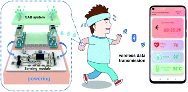
Thin, soft, skin electronics have attracted great attention for their use in the fields of healthcare monitoring and human–machine interfaces. The power supply is always one of the key issues in skin electronics, as it provides electrical energy to sensors, wireless communication modules, chips, and so on. However, traditional batteries generally have limitations such as rigid formats, large volume, or even potential safety issues by hazard materials, which might not be applicable for skin electronics. Herein, we present an ultra-thin, soft and biocompatible sweat-activated battery, combining bio-inspired microfluidics with flexible electronic technologies. The sweat-activated battery can collect the human sweat in seconds and yield a power density up to 122 mW cm−2 and a discharge capacity of 8.33 mA h. The sweat-activated battery can provide sufficient power to drive the state-of-the-art wearable electronics for real-time monitoring physiological signals (including heart rate, blood oxygen and skin temperature) and wireless transmission to smartphones via Bluetooth.


image file: d2ta01154a-p1.tif

Xinge Yu

Dr Xinge Yu is currently an Associate Professor of Biomedical Engineering at City University of Hong Kong (CityU). Xinge Yu's research group is focusing on skin-integrated electronics for biomedical applications. He has published over 120 papers in Nature, Nature Materials, Nature Biomedical Engineering, Nature Communications, PNAS, Science Advances, etc. Dr Yu serves as associate editor/editorial member for 10 journals. Dr Yu is also the recipient of innovators under 35 China (MIT Technology Review), NSFC Excellent Young Scientist Fund (Hong Kong & Macao), New Innovator of IEEE NanoMed, and MINE Young Scientist Award.


Introduction

Thin, soft, skin electronics interfacing with human skin enable continuous and precise monitoring of various physiological signals.1,2 The advanced mechanical and electrical properties of skin electronics offer countless applications foreground in the fields of healthcare, competitive sports, entertainment, and education.3–5 Distinguished with conventional wearable electronics, skin electronics possess incomparable advantages of a comfortable and adhesive interface with the skin, and therefore, exhibit long-term wearability.6,7 Without any doubt, power supply is an indispensable component to support the electronics operation; however, most commercial solutions, i.e. lithium-based batteries and coin cells, might not be the ideal candidates for skin electronics, as they face inevitable hurdles of rigid formats and large volume.8,9 To solve this problem, various approaches such as the development of printed flexible batteries were reported,10 but the toxicity, flammability and environmental issues remain obstacles in directly applying these batteries on human body, especially for implanted devices.11 Recent flexible and biocompatible energy harvesting technologies that are capable of converting ambient light, human motion energy, and body temperature into electrical energy via photovoltaic cells, piezoelectric/triboelectric/thermoelectric nanogenerators, etc., offer a feasible powering solution.12–16 Unfortunately, most of these energy harvesters typically generate pulsed electrical signals with very low power density, which might not be able to drive the signal-processing and data transmission modules in electronics (that usually need power more than tens of milliwatts) and need additional energy storage components such as supercapacitors.9,17,18

The urgency of a general powering solution for skin electronics has driven research on advanced bioenergy-based technologies, which can be realized in flexible biocompatible formats with desirable electrical performance.19,20 Bioenergy generated from human body typically associates with biofluids such as sweat, tears, saliva, and urine. Among them, sweat is a readily acquired human biofluid that contains a great deal of chemicals and reflects the individuals' dynamic health status at the molecular level.21 Furthermore, the wide distribution of sudoriferous glands under the skin allows sweat to be an ideal and sustainable bioenergy source for bioenergy-based batteries.22 Recently, biofuel cells catalyzing glucose and lactate in human sweat for energy conversion have been developed and used in wearable flexible electronics.23,24 For example, Gao et al. reported a lactate biofuel cell, in which human sweat provides lactate for the cell. A power density of 3.5 mW cm−2 was obtained in such lactate biofuel cells, and flexible electronic devices can be driven by the cell with stable performance outputs for tens of hours.24 Nevertheless, the nature of the low surface electron transfer rate and the catalytic conversion rate of enzymes in biofuel cells limit the electrical output, which is far from comparable to that of current commercial batteries.9 A novel, promising and high-power-density sweat-activated battery (SAB) that uses water molecules in sweat as the natural and safe activating cue has been developed with a power density over 16.3 mW cm−2 and used in the skin electronics.19,25–27 The effective collection of sweat is an important indicator for SABs, as it determines the response time and electrical outputs; however, the research in this area is still in their infancy. Reported studies utilized cotton as a sweat collector, which took ∼0.1 mL cm−2 of sweat in hundreds of seconds to allow the battery to discharge stably.25 There is still huge room for the improvement of collection efficiency. In nature, a lot of natural organisms collect and transport water passively via wettability gradient (e.g., lotus leaf and Namib desert beetle's back),28 curvature effect (e.g., shorebird's beak, spider silk, and cactus spine),29 and ratchet mechanism (e.g., butterfly wing and Nepenthes alata peristome)30 for adapting the arid habitat. Microfluidics based on these biological structures may be a desirable solution for SABs to effectively collect sweat.

Herein, we report a thin, soft and biocompatible SAB, which is capable of collecting sweat with extremely high efficiency via a bio-inspired microfluidic system, and thus generates sufficient power for state-of-the-art biosensor modules in continuous multiplexed monitoring of key physiological signals. The microfluidic system is inspired by lizard skin and rice leaf, which incorporates an anisotropic surface, featured with parallel directional capillary channels and adjacent asymmetric saw-tooth-shaped bumps to facilitate the large-scale collection and unidirectional delivery of sweat toward the desired sites. Careful selection of functional materials and optimization of device structures are important; the SAB system is skin-safe, cost-effective and easy to process for flexible and wearable electronics applications, and the redox reaction of SAB cell could be conducted effectively with a yielding output voltage of 1.91 V and a power density up to 122 mW cm−2. To the best of our knowledge, this is the record high performance among all reported flexible sweat batteries and flexible aqueous batteries (Table S1). To identify the powering performance of the SAB, a soft skin-integrated biosensor module was developed and connected with the SAB for demonstrating the ability of continuous monitoring of biophysical signals (heart rate, blood oxygen and skin temperature), data processing, storage, and wireless transmission.

Results and discussion

Overview of the epidermal-integrated SAB platform

Fig. 1(a) shows the schematic illustration of the exploded-view construction for the soft skin-integrated SAB, that contains three parts of silicone (polydimethylsiloxane, PDMS) encapsulation cap, microfluidics, and battery reaction region. Fig. 1(b) and S1 show the integral constructions of the PDMS cap, where the thickness is only 3 mm. The grooves with a size of 7 mm × 25 mm × 2 mm on both sides of the PDMS cap are designed to place the SABs, and the evenly arranged small vacancies (1 mm3) on the top of the grooves are designed for gas circulation, which not only provide the oxygen needed for the cathode chemical reaction but also evaporate the excess sweat from the human body. Meanwhile, the middle flat part of the PMDS cap is used to bond the microfluidic system via van der Waals force. Fig. 1(c) displays the front side view of the microfluidics that guides sweat to arrive at the bottom cotton layer via the capillary force, and then exposes to the middle cotton layer for SAB discharging. Besides, the bottom cotton layer serves as a separator to avoid the direct contact between the magnesium (Mg) foil and human skin. The microfluidics with the relief structure of 0.1 mm height and Young's modulus of ∼67 kPa enable a soft surface to intimately couple with the skin on any location of the body without additional adhesive layers.3,31 The SABs are assembled from an AgO2/graphene mixed cathode (0.8 mm thickness), a dry cotton layer loaded with salt as salt bridges (0.8 mm thickness), and a Mg foil as the anode (0.1 mm thickness). When there is no sweat, the dry cotton layer keeps the SAB in an open circuit state that overcomes the problems of electrolyte leakage, as self- or over-discharge typically happened in traditional energy transformation technologies.32 During perspiration, the middle cotton layer absorbs the sweat to dissolve the KCl microparticles and offer an essential moist environment for electronically connecting the circuit (Fig. S2). In more detail, this cell uses a Mg foil as the anode active material for an oxidation reaction with a standard electrode potential (E°) of +2.37 V, and Ag2O and oxygen as the cathode active materials for a reduction reaction with standard electrode potentials of +0.34 V and +0.40 V, respectively. The salt solution acts as the electrolyte and undergoes a hydrolysis reaction with a standard electrode potential of −0.83 V. The potential difference between the cathode and the anode was calculated to be 1.88–1.94 V, but the actual operating voltage is slightly lower than the theoretical value due to the presence of polarization and interface impedance.33,34 The discharge process can be described by the following three reactions:
 
2Mg(s) → 2Mg2+(s) + 4e, (E° = +2.372 V)(1)
 
Ag2O(s) + H2O(aq) + 2e → 2Ag(s) + 2OH(aq), (E° = +0.34 V)(2-1)
 
O2(g) + 2H2O(aq) + 4e → 4OH(aq), (E° = +0.4 V)(2-2)
 
H2O → 2H+ + OH, (E° = −0.83 V)(3)
where s, g and aq refer to the solid, gaseous and aqueous states. Under this condition, the activated SABs generate useable and stable electricity for powering these microelectronic systems that can perform various functions such as healthcare monitoring, communications, and wireless display. The power density of this system can be regulated by connecting different SABs in series. The reactants and products in the process are all non-toxic and harmless, which make the SABs suitable for portable and wearable power sources. Fig. 1(d) and S3 show the front and side viewing photos of the SAB mounted on the volunteer's wrist. Fig. 1(e)–(g) and S4 show the superior deformability of the SAB platform in front and back views, which indicate that the SAB accommodates most body motions, including bending, twisting, and stretching. A lightweight of 3.89 g and high Young's modulus of ∼67 kPa provide a comfortable interactive interface with the skin, and the simple fabrication and low material cost enable the scalability and commercialization.

image file: d2ta01154a-f1.tif
Fig. 1 Overview of the soft, thin, biocompatible SAB. (a) Schematic illustration of the exploded view for a SAB. (b) Schematic diagram of the PDMS cap in the SAB. (c) Scheme showing the bio-inspired microfluidic system. (d) Photograph of the SAB platform mounted on the volunteer's wrist in the front view. Photographs of the SAB platform under states of (e) bending, (f) twisting and (g) stretching, demonstrating a superior deformability of this SAB platform. Scale bar: 5 mm.

Characteristics of microfluidic platforms

Sweat is one of the ways through which the body actively regulates the temperature and sudoriferous glands located in the dermis of the skin throughout the body. Most of the time, an adult unconsciously evaporates sweat of 600 to 700 mL within 24 h. While in hot summer or under exercising, this number may go up to 1000–3000 mL.17,22 Sufficient sweat provides a green biological source for the activation of a SAB-based energy storage system. However, people's perspiration varies due to individual differences. To solve the problem of too little localized sweat to activate the SAB cell, we designed a bio-inspired microfluidic system capable of spontaneously propelling sweat towards the SAB, and the importance of the bio-inspired microfluidics, including rapid sweat collection speed up to 114 μL s−1, collection capacity close to 100%, and the excellent recycling capacity, was systematically studied and shown in Fig. 2. We screened two candidates with anisotropic micro/nanostructured surfaces as references for the fabrication of microfluidic sweat collectors (Fig. 2(a)): (i) the skin of a Texas horned lizard, which possesses interconnected capillary channels that enable preferential delivery of droplets to the snout, and (ii) rice leaf (Oryza sativa) with the anisotropic arrangement of micropapillae that directly induces droplet rolling toward the plant base. Fascinated by their morphologies and functional principles, we designed a passive microfluidic sweat collector with a multilevel structure. This structure consists of twenty arrays of half-open, longitudinal microgrooves (width of 800 μm, thickness of 200 μm) and adjacent, asymmetric sawtooth-shaped bumps (width decreasing from 600 μm to 175 μm, pitch of 200 μm) (Fig. 2(b)). The parallel microgrooves facilitated continuous flow in the longitudinal direction but inhibited liquid spreading in the transverse directions due to the three-phase contact line (Fig. S5, Note S1). The interconnected sawtooth-shaped capillary channels further extend the liquid transport distance and ensure the flow reaching toward the end of each narrow section (Fig. 2(b)–(d), Note S2). Specifically, we demonstrated the unidirectional liquid transport capability by applying DI water mixed with rosy ink on the microfluidic channel. The liquid was directionally transported to the functionalized area of SAB (Fig. 2(e), S5 and S6, Movies 1 and 2), whereas the movement in the reverse direction was almost negligible.
image file: d2ta01154a-f2.tif
Fig. 2 Working principles and characteristics of the microfluidic system. (a) Photographs of the skin of a Texas horned lizard with interconnected capillary channels, and a rice leaf with anisotropic arrangement of micropapillae. (b)–(d) SEM images of the passive microfluidic sweat collector with a multilevel structure. Scale bar: 1 mm. (e) Photographs of deionized (DI) water mixed with rosy ink on this microfluidic sweat collector at different time periods, showing the design principle of a microfluidic platform. Scale bar: 5 mm. (f) Diagram of several parts of the human epidermis that are prone to sweating. (g) Plot of the relationship between DI water entering microfluidics and the water remaining. (h) Plot of the time taken by DI water to enter the microfluidics to be completely collected. (i) Relationship of the average absorption ratio by a salt bridge vs. the volume of DI water entering the microfluidics. (j) Plot of open-circuit voltages of the SAB with different DI water volumes exposed in a KCl salt bridge. (k) Plot of discharge capacities of the SAB with different concentrations of KCl salt bridges.

Fig. 2(f) shows the schematic illustrations of several parts of the human body that are prone to sweating, which can provide a reference of the installing SABs, such as neck, chest, and back. To explore the drainage capability of microfluidics, we used various volumes of DI water to stimulate the different amounts of perspiration in the human body. By measuring the change in the weight of microfluidics before and after DI water flow, it turned out that DI water was mostly absorbed by the bottom cotton layer, and only a very small amount, even negligible (less than 0.02%), remained in the microfluidics (Fig. 2(g)). Meanwhile, to verify the fast response of this SAB platform, the time taken by water to reach the boundary for the first time (τ1) and the time for complete water absorption by a bottom cotton layer (τ2) were recorded. τ1 is related to the use times of microfluidics changing the surface hydrophilia and is independent of the volume of water. In the first 30 cycles, the rate of flow was 114 μL s−1, but the rate decreased to 39 μL s−1 after recycling 50 times that is needed to renew by oxygen plasma treatment for 10 min. As demonstrated in Fig. 2(h), τ2 increased with the volume of water, especially, it took 39.25 s for 300 μL. Due to the large contact area between the middle and bottom cotton layers with an area ratio of 43%, the incoming water would quickly penetrate from the bottom cotton layer into the middle cotton layer, and then the SAB was activated and the circuit was electronically connected. This whole process took no more than 10 s, and the minimum sweat amount collected by microfluidics to activate the battery is only 20 μL. Fig. 2(i) and Table S2 show the results of the absorption capability of the middle cotton layer, and it was found that the SAB starts to work when 20 μL of water is added to the microchannel, and the electrochemical reaction speed of the SAB reaches the maximum when 100 μL of water is added into the microfluidics while the middle cotton cloth layer was completely soaked. Fig. 2(j) presents the relationship between the water volume in the middle cotton layer and the voltage outputs of the SAB, where the maximum electrical output is 1.91 V as 10 μL water was absorbed, and then the voltage stabilizes at 1.73 V when the water volume was more than 30 μL. Fig. 2(k) shows the discharge capacity of SABs as a function of salt bridge concentration (various quantities of KCl preloaded on the middle cotton layer), where the capacity was measured in the constant current discharge mode with the current set at 1 mA and the initial and cutoff voltages set at 2 V and 0 V, respectively. The capacity first increases with the increase in KCl concentration and then decreases. DI water without any KCl in the SAB yields a capacity of 1.06 mA h, and a maximum discharge capacity of 3.52 mA h can be obtained for a KCl concentration of 200 mM. A further increase in the KCl concentration results in a decrease in the capacity, for instance, 400 mM KCl concentration for 2.87 mA h. This decrement in capacity is due to the highly effective chloride ions (Cl) in the SABs and a trade-off between the stabilizing effect of Cl on the cathode and the corrosive effect of Cl on the Mg foil. The former is because Cl consumes Ag and forms an insoluble AgCl solid, so that the bidirectional reaction between Ag2O and Ag in the cathode becomes a unidirectional reduction reaction.19,35 The latter is due to the corrosiveness of Cl, which accelerates the consumption of the Mg foil and reduces the discharge capacity of the battery.36,37 The change in capacity at such Cl concentration could be negligible in practical applications because the Cl ion concentration in human sweat is well below the threshold limit of 10 mM.38

Characteristics of an SAB

It is well known that the choice of electrodes is vital for the discharge capacity and power density of the battery.39,40 The current as a function of time shown in Fig. 3(a) and S7 shows the corresponding average current values within 5 min of the SABs. The test of the current was performed by metering the open-circuit (OC, Fig. S8) voltage where the circuit connected with a fixed value resistor (five ohms) in series. It is obvious that the SAB with AgO2/graphene yields higher and stable outputs of 1.80 V@340 mA and 1.76 V@327 mA for mixture weight ratios of 1[thin space (1/6-em)]:[thin space (1/6-em)]1 and 2[thin space (1/6-em)]:[thin space (1/6-em)]1, while the discharge stops in SABs with a pure conductive carbon cloth and graphene/carbon cloth-based cathodes after running for 5 min and 10 min basically. The short lifetime is due to that both the pure carbon cloth and the graphene cathode use oxygen as a reactant (eqn (2-2)), but they provide limited binding sites for oxygen and poor solubility of oxygen in water. Further evidence is reflected by the voltage performance differences of SABs with the two mixing ratios of the Ag2O/graphene electrode (Fig. S8). In the first 1 h, the voltages of these two SABs are very similar, while the SAB with a greater Ag2O mixing ratio generates a higher voltage after 1 h, which is mainly because oxygen has been consumed in the early stage as oxygen is more oxidizing than Ag2O (as evidenced by the standard electrode potential of 0.4 V for oxygen and only 0.34 V for Ag2O.41,42); simultaneously, Ag2O dominates the reduction at the cathode. In addition, we introduced the carbon cloth as a conductive substrate of the cathode to load the active material of Ag2O and graphenes, and graphene paste as a conductive binder to make the Ag2O powder into a film as well as improve the large resistance of silver oxide (about 106 ohm).43 This simple strategy is compatible with the flexible electronics processes and overcomes the complicated processing steps such as sintering, applying binder and cold processing in traditional Ag2O-based batteries in electrochemical methods, and centrifugation, washing and drying after precipitation by mixing aqueous solutions containing silver and alkaline solutions in chemical methods.43,44 Besides, superior to the conventional fuel cells, both the cathode and the anode are insulating-binder-free electrodes that guarantee an easy transfer channel for electrons and ions, and a very fast response speed for SAB turning on.
image file: d2ta01154a-f3.tif
Fig. 3 Characteristics of the SAB. (a) Current of the SAB with different cathodes. (b) Effect of different salt loadings within the separator on the output performance of the SAB. (c) Evolution of output performance of the SAB with the pH of the incoming solution. (d) Power density as a function of voltage. (e) Discharge capacity of the SAB with a mass ratio of Ag2O to graphene and a KCl salt bridge of 200 mM, pH = 7.0. (f) Open-circuit voltage vs. the numbers of SABs connected in series within 30 min. Effect of mechanical deformation on the electrical response of the SAB: (g) bending, (h) folding and (i) twisting. Scale bar: 5 mm.

The effect of salt bridge on the electrical output is shown in Fig. 3(b) and S9, and the result indicates that KCl and NaCl would not affect the performance of SABs. However, a huge loss of capacity in SABs with a NH4Cl salt bridge can be found to be resulting from the corrosive nature of NH4Cl to the Mg foil.45 From Fig. 3(c) and S10, it can be observed that a neutral environment helps to establish a more stable solution condition and extend the operating time of the SAB. Based on these findings, we optimized the options of cathode, salt bridge and solution pH value; therefore, an exciting maximum current density of 332 mA cm−2 (Fig. S11) and a maximum power density of 122 mW cm−2 (Fig. 3(d)) can be achieved, which is much greater than that in the existing reports (Table S1). Accordingly, the discharge capacity of the SAB reaches up to 8.33 mA h as its output voltage drops from 1.744 V to 0 V (Fig. 3(e)). To verify the superiority of this SAB, we connected two, three, and four SABs in series to boost the OC voltage to 3.374 V, 4.853 V and 6.526 V (Fig. 3(f)), which are sufficient to meet the power consumption requirements of common flexible electronics such as wireless communication and signal processing.46 Besides, our SABs are soft to work stable under various mechanical deformations. Benefiting from the soft materials and simple device structures, the SABs can give a stable output voltage of about 1.75 V after bending to 30°, 60°, and 90° (Fig. 3(g)). In the folding test, the output voltage of the SAB shows a decrease from 1.74 V to ∼1.52 V under 180° folding in the middle, while the SAB can recover to its initial performance after releasing (Fig. 3(h)). Similarly, the twisting results presented in Fig. 3(i) also indicate the great flexibility and robust feature of the SAB, as only very small and recoverable jitters appear in the voltage profile during the twisting.

On-body real-time physiological signal monitoring, Bluetooth data transmission, and display in self-developed apps, powered by SABs

A soft, lightweight microelectronic module for real-time biophysical signal monitoring powered by our SAB platform was developed to demonstrate the practical application of the SABs. The microelectronic module is based on the state-of-the-art skin electronics that contains a sensing module, a Bluetooth module for data transmission and self-developed software. Advances in material selection and system integration enable the skin electronic mounting on the skin to track biophysical signals during exercise for a long term (Fig. 4(a)). Fig. 4(b) and S12 show the exploded view and simplified block diagram of the skin electronic. A photograph of the biosensing module appears in Fig. S13. After exercise and perspiration, the sweat can be collected by the microfluidics, and then SABs are activated to yield a 3.4 V voltage to drive the biosensing module. Here, the real sweat generated by the volunteers during their exercise successfully activated the SABs, demonstrating that our SAB system has no restrictions on sweat conditions and, in turn, proves the universality and superiority of this SAB system. Data are collected from a biophysical sensor module (heart rate, blood oxygen and temperature) and converted into two-byte formats to be transmitted by the Bluetooth module and displayed in the self-developed graphic user interface (GUI) on smartphones (Fig. 4(c)). During exercise, the smart phone could pair with the skin electronic mounted on various locations of the body (i.e., forehead, chest and back), thus allowing users to check real-time physiological biomarkers, adjust the exercise states and prevent dehydration.
image file: d2ta01154a-f4.tif
Fig. 4 On-body real-time physiological signal monitoring, Bluetooth data transmission, and display in the self-developed app, powered by SABs. (a) Photograph of the SAB-powered soft electronic system mounted on the human arm. (b) Schematic illustration of the exploded view of the soft microelectronics. (c) Photograph of the data transmission by a Bluetooth module and display on self-developed software in a cellphone. The real-time physiological signals (heart rate, blood oxygen (SpO2), and skin temperature) displayed during 10 min exercise of (d) walking mode and (e) jogging mode.

Upon attaching the skin electronic on a volunteer's wrist, the sensing module can be monitored and the biophysical data during 10 min of continuous walking and jogging can be recorded (Fig. 4(d) and (e)). When walking in a low exercise intensity, the heart rate was 80–90 beats per min (bpm), blood oxygen (SpO2) was stable at 94%, and the skin temperature was roughly within 31–32 °C, indicating that the volunteer was in a good physical condition.47,48 When the exercise intensity increased to moderate jogging, the intensity of cardiac pumping raised to provide sufficient energy for exercise, as reflected by an increase in the heart rate to 130–145 and a slight increase in blood oxygen to 98%. At the same time, prolonged muscle contraction generated tremendous heat, making the skin temperature also increase to 34–36 °C. To explore the maximum runtime of our SAB module, experiments were conducted six times. It was found that the maximum lifetime is about 40–50 min. The results of the real-time physiological signal monitoring during 48 min are shown in Fig. S14. These results highlight the application potentials of the SAB-powered skin electronics for continuous healthcare monitoring. Benefiting from the advantages of lightweight, mechanical flexibility, biocompatibility and high electrical output, the SABs provide great support as a utility and a portable energy source for the rapid development of skin-integrated microelectronics.

Conclusion

In conclusion, we have developed a thin, soft, biocompatible sweat-activated battery platform, which is capable of softly laminating onto a curved skin surface, collecting human sweat, and yielding a high power density up to 122 mW cm−2 and a discharge capacity of 8.33 mA h. The SAB was tested under various mechanical deformations (such as bending, folding, and twisting), demonstrating the robust and ultra-flexible feature, and therefore, the long-term and stable wearability on the human skin. Connecting two SABs in series can generate sufficient power to drive a self-developed skin electronic device for continuously monitoring biophysical indicators (including heart rate, blood oxygen and skin temperature) and transmitting the data to the GUI on smartphones via Bluetooth. The material selection, microfluidics design, integration strategies and working mechanisms of the SAB in this work build a strong foundation for wearable power management.

Experimental section

Fabrication of the SAB

The fabrication began with using laser to cut a polished Mg anode (100 μm thick) and cathode (conductive carbon cloth, WOS1002, 0.4 mm thick, 4.0 ohm sq−1) substrate into 5 mm × 5 mm size. Subsequent blade coating of the mixture of Ag2O and a graphene slurry in weight ratios of 0[thin space (1/6-em)]:[thin space (1/6-em)]1, 1[thin space (1/6-em)]:[thin space (1/6-em)]1, and 2[thin space (1/6-em)]:[thin space (1/6-em)]1 was made on both sides of the cutting carbon cloth, which resulted in a high-efficiency anode current collector, and then, the cathode was dried in an oven at 60 °C for 15 min. The mass of the Mg foil is ∼40 mg and the mass of active materials in carbon cloth is ∼78 mg. A KCl solution of different concentrations, namely, 0 mM, 50 mM, 100 mM, 200 mM, 300 mM and 400 mM with the same volume of 10 μL, corresponding to the amount of KCl of 0 mg, 0.37 mg, 0.75 mg, 1.49 mg, 2.22 mg, and 2.98 mg, respectively, was applied to the middle-patterned cotton layer (0.5 mm × 2.5 mm × 0.8 mm). This was followed by thorough drying at room temperature to obtain a dry salt bridge with different KCl loadings. The Ag2O/graphene cathode, dry salt bridge, and the Mg anode were sequentially stacked with designed chambers and the embedded SBAs were formed. The OC voltage was measured by data acquisition using PowerLab (PL3516/P Powerlab 16/35, AD Instruments, sampling rate: 1000 Hz). The current was calculated by measuring the voltage of five ohms resistor as the load. The discharge capacity and power density were obtained using an electrochemical workstation of CHI660E. The capacity is the product of discharge time and discharge current (setting to 1 mA), and the power density is the product of discharge voltage and current density, in which the current density was calculated from the reaction area of electrodes (0.25 mm2).

Fabrication of the soft microfluidic system

Silicon wafers as substrates were ultrasonically cleaned sequentially with isopropyl alcohol (IPA), acetone, deionized water, and IPA. Before use, they were treated with an oxygen plasma for 15 min. Patterning of the microfluidic system (with a thickness of 100 μm) was achieved by spin coating photoresist (SU8 2050) at 3000 rpm for 30 s, followed by baking at 65 °C for 3 min and 95 °C for 5 min, and then exposed to ultraviolet light (Aligner System, URE 2000) for 5 s and post-baked at 95 °C for 5 min. For development, the samples were rinsed in a fresh SU8 developer for 5 min to yield an SU8 mold with clear microfluidic patterns. To peel off the PDMS more easily, the SU8 mold was soaked in a volatile chlorotrimethylsilane solution for 12 h. Pigmented silicone was added into transparent PDMS (with a curing ratio of 10[thin space (1/6-em)]:[thin space (1/6-em)]1) to yield a white silicon suspension. Then, 4.5 g of this PDMS was casted onto the SU8 mold and cured at 60 °C for 3 h. Upon release, the microfluidic platform with 0.1 mm height a soft relief structure was obtained. To encapsulate the SABs and fix the microfluidic system, PDMS capping with a curing ratio of 30[thin space (1/6-em)]:[thin space (1/6-em)]1 was created by releasing from a tailor-made resin mold made by the 3D printing technology. The SAB platform was obtained by assembling SABs into PDMS capping and then sticking the microfluidic system on PDMS capping by a hot pressing method, which was necessary for contact surfaces to treat with ultraviolet radiation for 15 min.

Fabrication of the soft microelectronic system

The soft skin electronic device consists of a PI substrate (25 μm thickness), a flexible circuit and electronic components. Circuit patterns were obtained by a printed circuit board processing technology, which was followed by plating a 50 nm-thick gold film onto a 10 μm-thick copper substrate. Electronic components including microcontrollers (CC2640R2F, TI), heart rate/SpO2/temperature sensors (MAX30102EFD+, MI), resistors, capacitors, and inductors were soldered on the flexible circuit with solder paste. Ultrathin PDMS (30[thin space (1/6-em)]:[thin space (1/6-em)]1) adhesive layer was used to adhere the flexible electronic system comfortably onto the human epidermis.

Author contributions

M. Wu, R. Shi, and J. Zhou co-conceived the work, designed the experiments, and wrote the initial draft. R. Shi, T. Wong, K. Yao and J. Li performed the microfluidics fabrication and characteristics. X. Huang, Y. Gao, D. Li assisted M. Wu with the fabrication of encapsulation cap and battery. J. Zhou, Y. Liu and S. Hou assisted with design and fabrication of microelectronic module, and test in various exercise modes. J. Yu and X. Yu co-conceived, supervised the work, and revised and edited the final manuscript.

Conflicts of interest

There are no conflicts to declare.

Acknowledgements

This work was supported by the National Natural Science Foundation of China (NSFC) (Grant No. U21A20492, 62122002), City University of Hong Kong (Grants No. 9667221, 9680322), Research Grants Council of the Hong Kong Special Administrative Region (Grant No. 21210820, 11213721), Shenzhen Science and Technology Innovation Commission (Grant No. JCYJ20200109110201713), Hong Kong Centre for Cerebro-cardiovascular Health Engineering (COCHE). This work was also sponsored by the Sichuan Province Key Laboratory of Display Science and Technology, and Qiantang Science & Technology Innovation Center. M. Wu thanks the Academic Support Program for PhD students supported by UESTC.

References

  1. J. A. Rogers, Nat. Nanotechnol., 2017, 12, 839–840 CrossRef CAS PubMed .
  2. H. Jeong, J. Y. Lee, K. Lee, Y. J. Kang, J.-T. Kim, R. Avila, A. Tzavelis, J. Kim, H. Ryu and S. S. Kwak, Sci. Adv., 2021, 7, eabg3092 CrossRef PubMed .
  3. X. Yu, Z. Xie, Y. Yu, J. Lee, A. Vazquez-Guardado, H. Luan, J. Ruban, X. Ning, A. Akhtar and D. Li, Nature, 2019, 575, 473–479 CrossRef CAS PubMed .
  4. Q. Yang, T. Wei, R. T. Yin, M. Wu, Y. Xu, J. Koo, Y. S. Choi, Z. Xie, S. W. Chen and I. Kandela, Nat. Mater., 2021, 20, 1559–1570 CrossRef CAS PubMed .
  5. S. Wang, J. Xu, W. Wang, G.-J. N. Wang, R. Rastak, F. Molina-Lopez, J. W. Chung, S. Niu, V. R. Feig and J. Lopez, Nature, 2018, 555, 83–88 CrossRef CAS PubMed .
  6. D.-H. Kim, N. Lu, R. Ma, Y.-S. Kim, R.-H. Kim, S. Wang, J. Wu, S. M. Won, H. Tao and A. Islam, science, 2011, 333, 838–843 CrossRef CAS PubMed .
  7. J. R. Sempionatto, M. Lin, L. Yin, K. Pei, T. Sonsa-ard, A. N. de Loyola Silva, A. A. Khorshed, F. Zhang, N. Tostado and S. Xu, Nat. Biomed. Eng., 2021, 5, 737–748 CrossRef CAS PubMed .
  8. B. Liu, Y. Jia, C. Yuan, L. Wang, X. Gao, S. Yin and J. Xu, Energy Storage Mater., 2020, 24, 85–112 CrossRef .
  9. M. Wu, K. Yao, D. Li, X. Huang, Y. Liu, L. Wang, E. Song, J. Yu and X. Yu, Mater. Today Energy, 2021, 21, 100786 CrossRef .
  10. L. Yin, J. Scharf, J. Ma, J.-M. Doux, C. Redquest, V. L. Le, Y. Yin, J. Ortega, X. Wei and J. Wang, Joule, 2021, 5, 228–248 CrossRef CAS .
  11. S. Mukherjee, A. Albertengo and T. Djenizian, Energy Storage Mater., 2021, 42, 773–785 CrossRef .
  12. Y. Lei, Y. Chen, R. Zhang, Y. Li, Q. Yan, S. Lee, Y. Yu, H. Tsai, W. Choi and K. Wang, Nature, 2020, 583, 790–795 CrossRef CAS PubMed .
  13. J. Park, Y. Lee, M. Ha, S. Cho and H. Ko, J. Mater. Chem. B, 2016, 4, 2999–3018 RSC .
  14. Y. Song, Z. Shi, G.-H. Hu, C. Xiong, A. Isogai and Q. Yang, J. Mater. Chem. A, 2021, 9, 1910–1937 RSC .
  15. T. H. Wong, Y. Liu, J. Li, K. Yao, S. Liu, C. K. Yiu, X. Huang, M. Wu, W. Park and J. Zhou, Adv. Funct. Mater., 2021, 2111269 Search PubMed .
  16. T. Wong, C. Yiu, J. Zhou, Z. Song, Y. Liu, L. Zhao, K. Yao, W. Park, W. Yoo and E. Song, Soft Science, 2021, 1(10) DOI:10.20517/ss.2021.09 .
  17. J. Lv, I. Jeerapan, F. Tehrani, L. Yin, C. A. Silva-Lopez, J.-H. Jang, D. Joshuia, R. Shah, Y. Liang and L. Xie, Energy Environ. Sci., 2018, 11, 3431–3442 RSC .
  18. G. Wu, S. Sun, X. Zhu, Z. Ma, Y. Zhang and N. Bao, Angew. Chem., Int. Ed., 2022, 61, e202115559 CAS .
  19. A. Bandodkar, S. Lee, I. Huang, W. Li, S. Wang, C.-J. Su, W. Jeang, T. Hang, S. Mehta and N. Nyberg, Nat. Electron., 2020, 3, 554–562 CrossRef CAS .
  20. J. Lv, G. Thangavel, Y. Li, J. Xiong, D. Gao, J. Ciou, M. W. M. Tan, I. Aziz, S. Chen and J. Chen, Sci. Adv., 2021, 7, eabg8433 CrossRef CAS PubMed .
  21. L. Manjakkal, L. Yin, A. Nathan, J. Wang and R. Dahiya, Adv. Mater., 2021, 2100899 CrossRef CAS PubMed .
  22. M. Bariya, H. Y. Y. Nyein and A. Javey, Nat. Electron., 2018, 1, 160–171 CrossRef .
  23. A. Ruff, F. Conzuelo and W. Schuhmann, Nat. Catal., 2020, 3, 214–224 CrossRef CAS .
  24. Y. Yu, J. Nassar, C. Xu, J. Min, Y. Yang, A. Dai, R. Doshi, A. Huang, Y. Song and R. Gehlhar, Sci. Robot., 2020, 5(41), eaaz7946 CrossRef PubMed .
  25. Y. Liu, X. Huang, J. Zhou, J. Li, S. K. Nejad, C. K. Yiu, H. Li, T. H. Wong, W. Park and K. Yao, Nano Energy, 2022, 92, 106755 CrossRef CAS .
  26. Y. L. X. Huang, J. Zhou, S. Nejad, T. Wong, Y. Huang, H. Li, C. Yiu, W. Park, L. Li, J. Su, L. Zhao, K. Yao, Z. Gao, M. Wu, D. Li, R. Shi and X. Yu, npj Flexible Electron., 2022, 6(10) DOI:10.1038/s41528-022-00144-0 .
  27. Y. Liu, X. Huang, J. Zhou, C. K. Yiu, Z. Song, W. Huang, S. K. Nejad, H. Li, T. H. Wong and K. Yao, Adv. Sci., 2022, 9(9), 2104635 CrossRef PubMed .
  28. K. Liu, X. Yao and L. Jiang, Chem. Soc. Rev., 2010, 39, 3240–3255 RSC .
  29. J. Li, J. Li, J. Sun, S. Feng and Z. Wang, Adv. Mater., 2019, 31, 1806501 CrossRef PubMed .
  30. H. Dai, Z. Dong and L. Jiang, Sci. Adv., 2020, 6, eabb5528 CrossRef CAS PubMed .
  31. M. Wu, Z. Gao, K. Yao, S. Hou, Y. Liu, D. Li, J. He, X. Huang, E. Song and J. Yu, Mater. Today Energy, 2021, 20, 100657 CrossRef CAS .
  32. B.-K. Park and S. A. Barnett, J. Mater. Chem. A, 2020, 8, 11626–11631 RSC .
  33. H. Ao, Y. Zhao, J. Zhou, W. Cai, X. Zhang, Y. Zhu and Y. Qian, J. Mater. Chem. A, 2019, 7, 18708–18734 RSC .
  34. H. Kim, J. Hong, K.-Y. Park, H. Kim, S.-W. Kim and K. Kang, Chem. Rev., 2014, 114, 11788–11827 CrossRef CAS PubMed .
  35. X. Zhao, S. Ren, M. Bruns and M. Fichtner, J. Power Sources, 2014, 245, 706–711 CrossRef CAS .
  36. D. Li, J. Wang, D. Chen and P. Liang, J. Power Sources, 2014, 272, 448–456 CrossRef CAS .
  37. N. Job, M. Chatenet, S. Berthon-Fabry, S. Hermans and F. Maillard, J. Power Sources, 2013, 240, 294–305 CrossRef CAS .
  38. D.-H. Choi, J. S. Kim, G. R. Cutting and P. C. Searson, Anal. Chem., 2016, 88, 12241–12247 CrossRef CAS PubMed .
  39. S. K. Das, S. Mahapatra and H. Lahan, J. Mater. Chem. A, 2017, 5, 6347–6367 RSC .
  40. D. Selvakumaran, A. Pan, S. Liang and G. Cao, J. Mater. Chem. A, 2019, 7, 18209–18236 RSC .
  41. A. Holewinski, J.-C. Idrobo and S. Linic, Nat. Chem., 2014, 6, 828–834 CrossRef CAS PubMed .
  42. K. T. Braam, S. K. Volkman and V. Subramanian, J. Power Sources, 2012, 199, 367–372 CrossRef CAS .
  43. N. R. C. Raju, K. J. Kumar and A. Subrahmanyam, J. Phys. D: Appl. Phys., 2009, 42, 135411 CrossRef .
  44. M. Sabzi and S. Mersagh Dezfuli, Int. J. Appl. Ceram. Technol., 2018, 15, 1446–1458 CrossRef CAS .
  45. S. Kim, F. Loose and P. J. Chirik, Chem. Rev., 2020, 120, 5637–5681 CrossRef CAS PubMed .
  46. Y. S. Choi, R. T. Yin, A. Pfenniger, J. Koo, R. Avila, K. Benjamin Lee, S. W. Chen, G. Lee, G. Li and Y. Qiao, Nat. Biotechnol., 2021, 39, 1228–1238 CrossRef CAS PubMed .
  47. B. W. Nelson, C. A. Low, N. Jacobson, P. Areán, J. Torous and N. B. Allen, npj Digit. Med., 2020, 3, 1–9 CrossRef PubMed .
  48. H. U. Chung, A. Y. Rwei, A. Hourlier-Fargette, S. Xu, K. Lee, E. C. Dunne, Z. Xie, C. Liu, A. Carlini and D. H. Kim, Nat. Med., 2020, 26, 418–429 CrossRef CAS PubMed .

Footnote

Electronic supplementary information (ESI) available. See https://doi.org/10.1039/d2ta01154a

This journal is © The Royal Society of Chemistry 2022