
 Open Access Article
 This Open Access Article is licensed under a
 Creative Commons Attribution 3.0 Unported Licence
A La and Nb co-doped BaTiO3 film with positive-temperature-coefficient of resistance for thermal protection of batteries†
Min
Zhang
 a,
Sacha
Fop
ab,
Denis
Kramer
cde,
Nuria
Garcia-Araez
*af and
Andrew L.
Hector
*a
a,
Sacha
Fop
ab,
Denis
Kramer
cde,
Nuria
Garcia-Araez
*af and
Andrew L.
Hector
*a
aSchool of Chemistry, University of Southampton, Highfield, Southampton SO17 1BJ, UK. E-mail: N.Garcia-Araez@soton.ac.uk; A.L.Hector@soton.ac.uk
bISIS Facility, Rutherford Appleton Laboratory, Harwell OX11 0QX, UK
cFaculty of Mechanical Engineering, Helmut-Schmidt University, Holstenhofweg 85, Hamburg 22043, Germany
dSchool of Engineering, University of Southampton, Highfield, Southampton SO17 1BJ, UK
eHelmholtz Zentrum HEREON, Department of Heterogeneous Catalysis, Max-Planck-Strasse 1, Geesthacht 21502, Germany
fThe Faraday Institution, Quad One, Harwell Campus, Didcot OX11 0RA, UK
First published on 3rd May 2022
Abstract
Battery safety is the number one priority for consumers and manufacturers, particularly for large-scale applications like electric vehicles and distributed energy storage systems, where the consequences of thermal runaway events can be devastating. Here we propose a novel approach to prevent battery thermal runaway by using La and Nb co-doped BaTiO3. The material is incorporated into a battery system as a thin film, having no effects on the room temperature operation, but rapidly switching off the battery current at high temperatures due to the positive temperature coefficient of resistivity (PTCR) exhibited by doped BaTiO3. La and Nb as co-dopants of BaTiO3 are found to be critical to ensure good room temperature conductivity combined with a significant PTCR effect. This work demonstrates the use of a purely inorganic PTCR material for thermal runaway protection for the first time. The high mechanical and chemical stability of the BaTiO3-based material proposed here makes it an advantageous competitor to current polymer-based protective switches.
1. Introduction
Thermal runaway of lithium-ion batteries is, by far, the most common cause of battery accidents.1 Thermal runaway is triggered by forcing the battery to operate outside of its specifications, for instance via the application of mechanical abuse (crush or penetration), electrical abuse (short-circuit or overcharge) or thermal abuse (overheat).2–6 The abuse induces degradation reactions inside the battery, and when the rate of heat generation induced by the degradation of the battery exceeds the rate of heat dissipation, then the increase in temperature of the battery accelerates. Thermal runaway is the increasing temperature loop and it can lead to battery fires and explosion.Multiple safety strategies have been developed to prevent thermal runaway, like the incorporation of external devices, such as thermal fuses or safety vents, that cut the current flow through the battery.7,8 Additionally, battery material components producing thermal runaway protection have also been developed, such as thermal shutdown separators, temperature-sensitive electrodes, or thermally polymerizable electrolytes.9–17 These systems are particularly advantageous because the protection is achieved directly inside the battery, without time delays or complications associated with the transmission of the temperature wave to an external device. Indeed, previous studies have found that the internal temperature of commercial prismatic cells vastly exceeds the external surface temperature, even before fire.18,19 However, these internal safety components also have some shortcomings: thermal shutdown separators can ‘meltdown’ at high temperatures, thus shorting the electrodes and producing violent reactions;8,20 temperature-sensitive electrodes usually require complex materials or electrode preparations; and thermally polymerizable electrolytes are not always fully compatible with the battery electrodes.21,22 Thus, the incorporation of additional protection measures is required to ensure safety in large-scale applications.
The core mechanism of internal safety protection against thermal runaway is based on the incorporation of a battery component whose resistivity dramatically increases with temperature, and thus significantly reduces the current flow through the battery. This effect is called ‘positive temperature coefficient of resistivity’ (PTCR) and PTCR materials for battery protection have been successfully demonstrated using a range of functional polymer composites.15,23–30 However, purely inorganic PTCR materials have never been applied inside the batteries to prevent thermal runaway, although the mechanical and high temperature chemical stability of inorganic materials offers advantages over polymer composites (ESI, Tables S1 and S2†).31–35
Here we demonstrate, for the first time, the use of a doped BaTiO3 thin film as an internal PTCR material for battery thermal runaway protection. The PTCR effect in BaTiO3 has been widely used in external devices such as thermistors. BaTiO3 is an insulator, but donor doped BaTiO3 exhibits semiconducting behaviour at room temperature, and an increase in resistivity (PTCR effect) is observed near the Curie temperature, during which a phase transition from a ferroelectric tetragonal to a paraelectric cubic phase occurs.36 The PTCR in BaTiO3 is a grain boundary effect that can be explained by the Heywang–Jonker model.37,38 According to this model, the existence of a potential barrier along the grain boundary is responsible for the increased resistivity of the grain boundary compared to the grain interior. This barrier is generated by a layer of acceptor states at the grain boundary, which attracts electrons from the bulk grain to form an electron depletion layer.37 The acceptor states are formed by oxygen vacancies, barium vacancies, segregated titanium and/or dopant cations, which can act as electron traps at the grain boundary.36,39–42 At room temperature, ferroelectric BaTiO3 exhibits a spontaneous polarization along the tetragonal crystal axis, which decreases the height of the potential barrier at the grain boundary, leading to a low resistivity. Above the Curie temperature, BaTiO3 transitions to a cubic paraelectric phase, the spontaneous polarization vanishes, and the potential barrier becomes fully effective resulting in a rapid increase in resistivity.38
The very dramatic change in resistivity exhibited by BaTiO3-based materials due to the PTCR effect makes them highly promising to stop the current flow through a battery in a thermal runaway event. However, the materials reported previously exhibit either insufficient room temperature conductivity, or high room temperature conductivity but insufficient PTCR effect within the temperature range of battery failure.36 Here we report the use of a La and Nb co-doped BaTiO3 thin film as an internal PTCR material for battery thermal runaway protection. A solid-state-based synthesis method is developed to produce robust self-standing films with a good room temperature conductivity and significant PTCR effect. The effects of La and/or Nb doping on the microstructure, morphology and electrochemical properties of the film are systematically investigated. The optimised film is incorporated into LiFePO4-graphite and LiCoO2-graphite batteries, in between the cathode and the spacer in coin cells. Our results show that the film provides efficient protection during overheating and overcharging without compromising the battery room temperature performance. This study demonstrates that the use of inorganic PTCR materials is a promising internal thermal protection approach, which can reinforce battery safety under abuse conditions.
2. Experimental
2.1. Materials synthesis and characterisation
The undoped, La-doped, Nb-doped and La–Nb-co-doped BaTiO3 samples with various doping amounts were synthesized via a solid-state method. The precursors were BaCO3 (≥99.999% purity, Sigma Aldrich), TiO2 (≥99% purity, Sigma Aldrich), La2O3 (≥99.99% purity, Sigma Aldrich) and Nb2O5 (≥99.99% purity, Sigma Aldrich). The compositions have the formula (Ba1−xLax)(Ti1−yNby)O3, where x = y = 0 for undoped BaTiO3 sample (denoted as BTO); x = 0.003, 0.006, 0.009 and y = 0 for La-doped BaTiO3 samples (denoted as BTO-L3, BTO-L6, BTO-L9); x = 0 and y = 0.002, 0.004, 0.006 for Nb-doped BaTiO3 samples (denoted as BTO-N2, BTO-N4, BTO-N6); x = 0.003 and y = 0.002, 0.004, 0.006 for La–Nb-co-doped BaTiO3 samples (denoted as BTO-L3N2, BTO-L3N4, BTO-L3N6). All the precursors were dried and dehydrated before being fully mixed by grinding in acetone and ball milling in deionized water. The mixture was dried, ground and sieved, then pressed into a pellet, and pre-fired at 1150 °C for 2 h in air. The pre-fired pellet was ground in acetone, and the obtained powder was fully mixed with 0.5 at% BaCO3 and 0.05 at% SiO2 by ball milling in deionized water, then dried and sieved to achieve fine powders. After that, the fine powder was mixed with polyvinyl butyral, dibutyl phthalate, tributyl phosphate, trichloroethylene and ethanol in a weight ratio of about 1![[thin space (1/6-em)]](https://www.rsc.org/images/entities/char_2009.gif) :0.1:0.1:0.05:0.6:0.9 to form a slurry. The slurry was cast onto a tungsten substrate using a doctor-blade method, then the formed sheet was dried at room temperature and cut into circular discs with thickness of ∼200 μm. The discs were heated at 430 °C for 2 days in air to remove the binder and organics, then sintered at 1350 °C for 2 h under 5% H2 in N2. The sintered discs were finally re-oxidised at 800 °C for 1 h in air to obtain the undoped and La and/or Nb doped BaTiO3 PTCR films.
:0.1:0.1:0.05:0.6:0.9 to form a slurry. The slurry was cast onto a tungsten substrate using a doctor-blade method, then the formed sheet was dried at room temperature and cut into circular discs with thickness of ∼200 μm. The discs were heated at 430 °C for 2 days in air to remove the binder and organics, then sintered at 1350 °C for 2 h under 5% H2 in N2. The sintered discs were finally re-oxidised at 800 °C for 1 h in air to obtain the undoped and La and/or Nb doped BaTiO3 PTCR films.
X-ray diffraction measurements were carried out with a Bruker D2 Phaser with Cu-Kα radiation. Rietveld analysis was performed using the GSAS package.43 Raman spectroscopy measurements were carried out with a Renishaw inVia confocal microscope, and the data were analysed using the WiRE 4.1 software. Scanning electron microscopy (SEM) micrographs were collected on a JEOL SM-54220LNT operated at 15 kV, and images were analysed using the ImageJ software and Gaussian function. Electrochemical tests were performed with a Biologic potentiostat. The conductivities and PTCR effects were determined from the current–voltage measurements on undoped and La and/or Nb doped BaTiO3 discs with diameters of ∼11 mm and thicknesses of ∼200 μm, and with a ∼20 nm gold coating evaporated onto each side of the discs. Current–voltage plots were collected at 20 mV s−1 over the range of −0.3 to +0.3 V at different temperatures.
2.2. Battery fabrication, electrochemistry and safety evaluation
LiFePO4 and LiCoO2 electrodes were prepared by mixing LiFePO4 or LiCoO2 (Tatung), conductive carbon black (Super C65, Timcal) and polyvinylidene difluoride (PVDF 5130, Solvay) with a mass ratio of 92:4:4 in N-methyl-2-pyrrolidone (NMP, anhydrous, ≥99.8% purity, Sigma-Aldrich). The slurry was cast onto an Al foil (40 μm thick, ≥99% purity, Advent Research Materials) and dried at 120 °C under vacuum for 12 h. The foil was cut into circular discs with a diameter of 11 mm and pressed at 2 tons to obtain LiFePO4 or LiCoO2 cathodes. Swagelok cells were assembled in an argon-filled glove box with LiFePO4 or LiCoO2 cathodes, lithium foil (Rockwood Lithium) anodes and separators (glass microfiber filter, GF/F grade, Whatman or Celgard 2400 monolayer microporous membrane) soaked in the 1 M LiPF6 in ethylene carbonate/ethyl methyl carbonate (EC:EMC = 3:7 in volume) electrolyte (PuriEL, Soulbrain). Similarly, graphite electrodes for use in full lithium-ion cells were prepared by mixing the graphite (MAGE3, Hitachi), carbon black and PVDF with a mass ratio of 94:3:3 in NMP. The slurry was cast onto a Cu foil (50 μm thick, ≥99% purity, Advent Research Materials) and dried at 120 °C under vacuum for 12 h. The foil was cut into circular discs and pressed at 2 tons to obtain graphite anodes. Coin cells (CR2032) were assembled in an argon-filled glove box with LiFePO4 or LiCoO2 as cathodes and graphite as anodes. The La–Nb-co-doped BaTiO3 PTCR film (thickness ∼200 μm) was placed in between the cathode and the spacer (in coin cell) or between the cathode and the cathode plunger (in Swagelok cell). This robust self-standing PTCR film exhibited enough mechanical strength to resist the pressure in the coin/Swagelok cells without breaking.
Cyclic voltammetry measurements used a scan rate of 0.1 mV s−1 over the voltage range of 2.5–4.1 V. Galvanostatic charge/discharge tests were carried out at various rates of charge/discharge (e.g. 0.1C for a theoretical specific capacity of 170 mA h g−1 corresponds to a specific current of 17 mA g−1) within the voltage range of 2.5–4.1 V (vs. Li+/Li) for LiFePO4 battery (3.0–4.3 V for LiCoO2 battery) at different temperatures. Electrochemical impedance spectroscopy measurements were collected at the open circuit potential with a perturbation amplitude of 10 mV in the frequency range of 0.1 to 200 kHz at different temperatures.
Overcharging tests were carried out by constantly charging the full cells to either reaching 180% state of charge (SOC) or exceeding 10 V voltage at 0.4C current rate, with the voltage variations of the cell versus time being recorded by a Biologic potentiostat. Heating tests were characterised by heating the fully charged coin cells to 150 °C at 4 °C min−1, and keeping the cell at 150 °C for 60 min, with the voltage variations and temperature changes of the cell versus time being recorded by a Biologic potentiostat and a PicoLog TC-08 thermocouple data logger, respectively.
3. Results and discussion
3.1. Microstructure, morphology and electrochemical properties of La/Nb-doped BaTiO3 PTCR materials
The undoped, La-doped, Nb-doped and La–Nb-co-doped BaTiO3 samples with various doping amounts were produced via a solid state synthesis method, to determine the effect of element doping on the microstructure, morphology and electrochemical properties of BaTiO3 samples. Table 1 shows the sample labels used for La and/or Nb doped BaTiO3 samples with various doping amounts.| Sample | Composition | Lattice parameter | Tetragonality | Reliability factor | ||
|---|---|---|---|---|---|---|
| a [Å] | c [Å] | c/a | R wp | R p | ||
| BTO | BaTiO3 | 4.00271(9) | 4.01627(11) | 1.0034 | 0.112 | 0.0897 |
| BTO-L3 | (Ba0.997La0.003)TiO3 | 4.00158(6) | 4.01767(08) | 1.004 | 0.1337 | 0.1063 |
| BTO-L6 | (Ba0.994La0.006)TiO3 | 4.00018(7) | 4.01844(10) | 1.0046 | 0.1116 | 0.089 |
| BTO-L9 | (Ba0.991La0.009)TiO3 | 3.99920(9) | 4.02082(11) | 1.0054 | 0.1026 | 0.083 |
| BTO-N2 | Ba(Ti0.998Nb0.002)O3 | 4.00276(6) | 4.01601(08) | 1.0033 | 0.1345 | 0.1063 |
| BTO-N4 | Ba(Ti0.996Nb0.004)O3 | 4.00288(8) | 4.01451(10) | 1.0029 | 0.1096 | 0.0884 |
| BTO-N6 | Ba(Ti0.994Nb0.006)O3 | 4.00326(6) | 4.01400(08) | 1.0027 | 0.133 | 0.1042 |
| BTO-L3N2 | (Ba0.997La0.003)(Ti0.998Nb0.002)O3 | 3.99985(6) | 4.02231(08) | 1.0056 | 0.1363 | 0.1088 |
| BTO-L3N4 | (Ba0.997La0.003)(Ti0.996Nb0.004)O3 | 4.00083(6) | 4.01978(08) | 1.0047 | 0.129 | 0.1027 |
| BTO-L3N6 | (Ba0.997La0.003)(Ti0.994Nb0.006)O3 | 4.00149(8) | 4.01922(11) | 1.0044 | 0.1329 | 0.1025 |
The XRD patterns of undoped, La-doped, Nb-doped and La–Nb-co-doped BaTiO3 samples (Fig. 1a) show that the tetragonal BaTiO3 phase (space group P4mm) has been prepared throughout with no impurity phases detected after La and Nb doping.44 The shift in the 101/110 reflection positions indicates that the La and Nb doping changes the lattice parameters of BaTiO3. The undoped and doped BaTiO3 samples exhibit a tetragonal structure, as clearly seen by the split of, for example, the 101/110 and 200/002 reflections as shown in Fig. 1a.45 The formation of a tetragonal structure and changes in lattice parameters for La and/or Nb doped BaTiO3 samples can be confirmed via Rietveld fits (ESI, Fig. S1†) to the XRD data. The obtained lattice parameters (a and c) and reliability factors (Rwp, Rp) are listed in Table 1. The La and Nb are likely to substitute on the Ba and Ti site, respectively, as the ionic radii of La3+ (1.36 Å) and Nb5+ (0.64 Å) are close to those of Ba2+ (1.61 Å) and Ti4+ (0.605 Å), respectively.36,46 The Rietveld fits are consistent with this assumption. As shown in Fig. 1b, for La-doped BaTiO3 samples, the lattice parameter a decreases with the increasing amount of La doping from 0 to 0.9 at%, as Ba2+ has been replaced by the aliovalent La3+ with smaller ionic radius. The value of c/a has been used to denote the degree of tetragonal distortion, also known as tetragonality.47 Tetragonality is an important parameter in defining the PTCR characteristics of doped BaTiO3, directly affecting the Curie temperature and the magnitude of the PTCR jump.48,49 The increasing c/a value suggests that the tetragonality of the crystal structure increases with the amount of La doping. For Nb-doped BaTiO3 samples, the lattice parameter a increases with the increasing amount of Nb doping from 0 to 0.6 at%, as the Ti4+ has been replaced by the aliovalent Nb5+ with slightly larger ionic radius, while the lattice parameter c decreases. The resultant decreasing c/a value suggests that the tetragonality of the crystal structure decreases with the increasing amount of Nb doping. For La–Nb-co-doped BaTiO3 samples, the La doping amount remained at 0.3 at%, while the Nb doping amount was increased from 0.2 to 0.6 at%. Comparing with the undoped BaTiO3 sample, the lattice parameter a decreases after co-doping with 0.3 at% La and 0.2 at% Nb, then increases after increasing the Nb doping amount from 0.2 to 0.6 at%. Accordingly, the tetragonality of the crystal structure increases after La and Nb co-doping, then decreases with the increasing Nb doping concentration. This trend is consistent with the results obtained from the Nb-doped BaTiO3 samples. For La–Nb-co-doped BaTiO3 samples, the crystal structure of BaTiO3 has been affected by both La and Nb doping, and the BaTiO3 with 0.3 at% La and 0.2 at% Nb co-doping exhibits the highest tetragonality.
 | ||
| Fig. 1 (a) XRD patterns of undoped, La-doped, Nb-doped and La–Nb-co-doped BaTiO3 samples; enlarged XRD patterns to highlight the shift in the peak position and the split of 101/110 reflections (middle); enlarged XRD patterns of the split of 200/002 reflections (right). (b) Lattice parameters (a, c) and tetragonality (c/a) against samples with various doping elements and amounts (sample labels explained in Table 1). | ||
The formation of a tetragonal structure and changes in tetragonality of undoped, La-doped, Nb-doped and La–Nb-co-doped BaTiO3 samples can also be confirmed by Raman spectroscopy. As shown in Fig. 2a, the Raman spectrum of tetragonal BaTiO3 exhibits the Raman-active modes E(TO), A1(TO) at ∼180 cm−1, A1(TO) at ∼270 cm−1, E(LO + TO), B1 at ∼307 cm−1, E(TO), A1(TO) at ∼515 cm−1 and E(LO), A1(LO) at ∼720 cm−1, while cubic BaTiO3 is Raman-inactive.47,50 It has been reported that the sharp peak at ∼307 cm−1 (shaded in Fig. 2a) is particularly sensitive to the tetragonality of the crystal structure, with its intensity increasing when BaTiO3 becomes more tetragonal.47,50 The integrated intensity of the peak at 307 cm−1 for each sample relative to that of the undoped BaTiO3 sample has been used to qualitatively evaluate the tetragonality after La and/or Nb doping.47,51,52 In Fig. 2b, the relative integrated intensities of the peak at 307 cm−1 are plotted vs. various doping elements and amounts. For La-doped BaTiO3 samples, the integrated intensity of the peak at ∼307 cm−1 increases with the increasing amount of La doping, suggesting that the tetragonality of the crystal structure increases after La doping. For Nb-doped BaTiO3 samples, the tetragonality of the crystal structure decreases after Nb doping, as the integrated intensity of the ∼307 cm−1 peak decreases with the increasing amount of Nb doping. For La–Nb-co-doped BaTiO3 samples, compared with the undoped BaTiO3 sample, the integrated intensity of the peak at ∼307 cm−1 increases after co-doping with 0.3 at% La and 0.2 at% Nb, then decreases when increasing the Nb doping amount from 0.2 to 0.6 at%. The BaTiO3 with 0.3 at% La and 0.2 at% Nb co-doping exhibited the highest tetragonality. This trend is consistent with the result obtained from the XRD Rietveld analysis. Both XRD and Raman characterisations confirmed that La and Nb have been doped into the phase-pure BaTiO3 phase with a concomitant change of tetragonality.
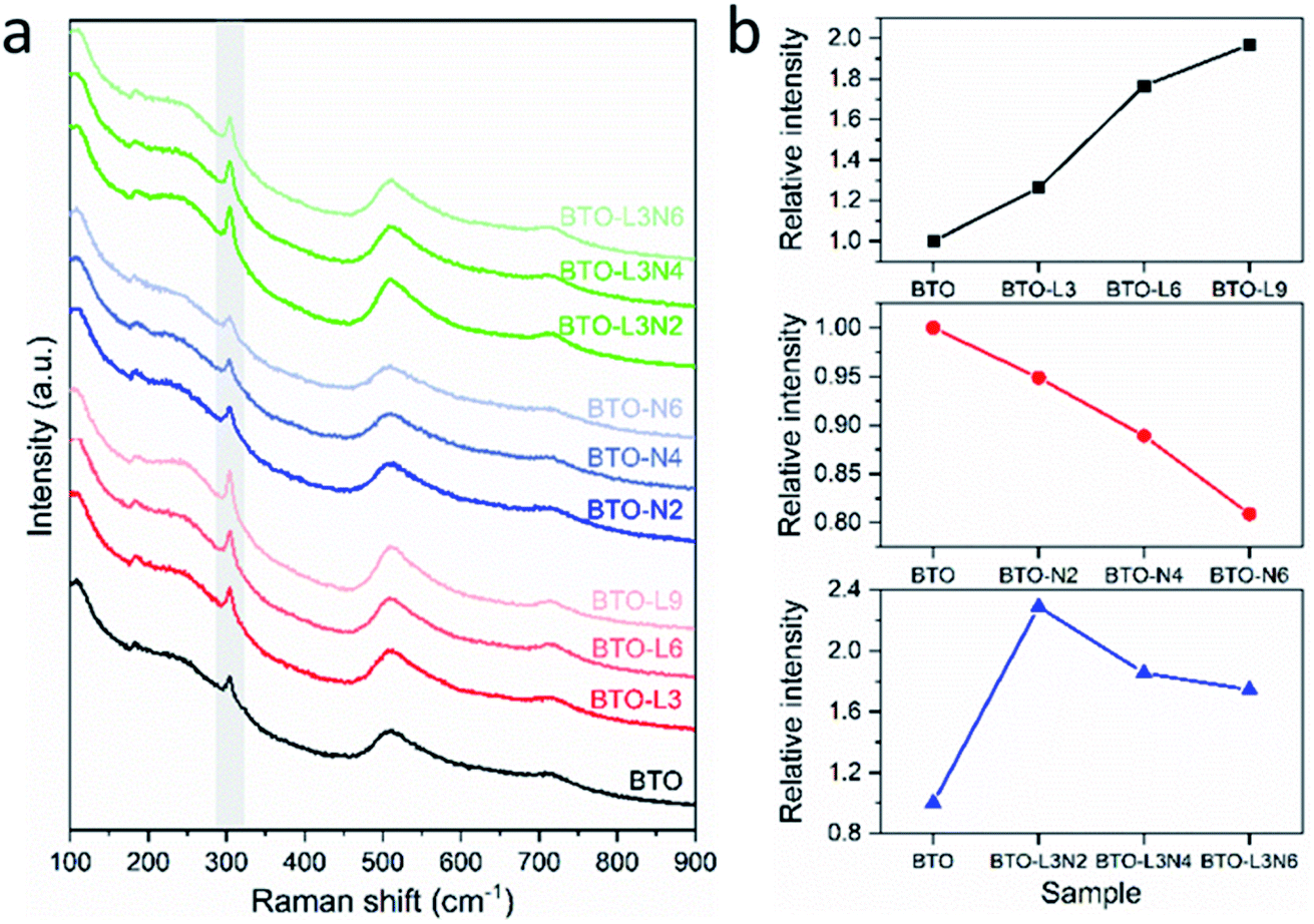 | ||
| Fig. 2 (a). Raman spectra of undoped, La-doped, Nb-doped and La–Nb-co-doped BaTiO3 samples (peaks at ∼307 cm−1 being marked as shaded). (b). Relative integrated intensities of the Raman peak at 307 cm−1, as a function of BaTiO3 samples with various doping elements and amounts (sample labels explained in Table 1). | ||
The grain sizes of undoped, La-doped, Nb-doped and La–Nb-co-doped BaTiO3 samples were determined from analysing SEM images using the ImageJ software, and the size distributions were obtained by fitting with a Gaussian function. The SEM images and grain size distributions of the samples are shown in Fig. 3a and ESI, S2,† and the average grain sizes of the samples are presented in Fig. 3b and Table 2. The undoped BaTiO3 shows an average grain size of 1.33 μm and a wide size distribution. The La and/or Nb doped BaTiO3 samples exhibit slightly smaller average grain sizes of 0.93–1.18 μm and narrower size distributions. As shown in Fig. 3b, the average grain size of the sample decreases with the increasing La or Nb doping concentration. This grain size reduction with La and/or Nb, even with a low doping concentration (≤0.9 at%), could be ascribed to the segregation of small amounts of doped donors and generated acceptors at the grain boundary, thus retarding the grain growth.53–57
 | ||
| Fig. 3 (a) SEM images of BTO, BTO-L3, BTO-N2, BTO-L3N2 samples. (b) Average BaTiO3 grain sizes determined from SEM images, as a function of various doping elements and amounts. (c) Room-temperature conductivity and PTCR effect of undoped, La-doped, Nb-doped and La–Nb-co-doped BaTiO3 samples (sample labels explained in Table 1). | ||
| Sample | Average grain size [μm] | Conductivity [S cm−1] | PTCR | |
|---|---|---|---|---|
| σ max | σ min | lg(σmax/σmin) | ||
| BTO | 1.33 | 4.05 × 10⁻⁷ | 9.55 × 10⁻¹⁰ | 2.63 |
| BTO-L3 | 1.18 | 2.28 × 10⁻³ | 1.77 × 10⁻⁵ | 2.11 |
| BTO-L6 | 0.96 | 4.90 × 10⁻⁵ | 2.33 × 10⁻⁷ | 2.32 |
| BTO-L9 | 0.93 | 7.59 × 10⁻⁷ | 2.23 × 10⁻⁹ | 2.53 |
| BTO-N2 | 1.17 | 2.42 × 10⁻³ | 2.14 × 10⁻⁵ | 2.05 |
| BTO-N4 | 1.06 | 2.27 × 10⁻³ | 2.11 × 10⁻⁵ | 2.03 |
| BTO-N6 | 1.01 | 2.19 × 10⁻³ | 2.13 × 10⁻⁵ | 2.01 |
| BTO-L3N2 | 1.03 | 2.71 × 10⁻³ | 1.58 × 10⁻⁵ | 2.23 |
| BTO-L3N4 | 1.02 | 2.56 × 10⁻³ | 1.54 × 10⁻⁵ | 2.22 |
| BTO-L3N6 | 0.98 | 2.49 × 10⁻³ | 1.58 × 10⁻⁵ | 2.20 |
The variations of the room temperature conductivity and PTCR effect of BaTiO3 samples after Nb and/or La doping are plotted in Fig. 3c. The PTCR effect was defined as the logarithm of the conductivity drop above the Curie temperature of ∼135 °C, with respect to room temperature, and it is denoted as lg(σmax/σmin). The conductivities listed in Table 2 are calculated from the current–voltage plots shown in ESI, Fig. S3.† For La-doped BaTiO3 samples, the 3 at% La-doped BaTiO3 sample (2.28 × 10⁻³ S cm−1) exhibits a much higher conductivity than undoped BaTiO3 (4.05 × 10⁻⁷ S cm−1) at room temperature. This has been attributed not only to the donor-doping electronic compensation of the La3+ substituted Ba2+ to create electronic defects (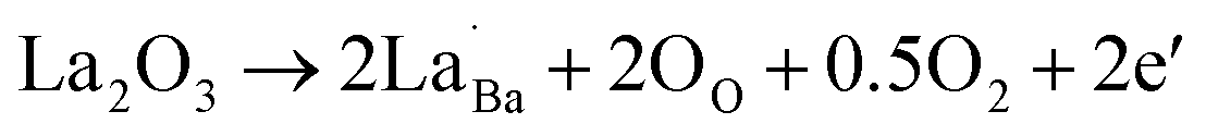 ), but also to the formation of oxygen vacancies to release free electrons (
 ).58,59 The dramatic increase in the room temperature conductivity is generally accompanied by a decrease in PTCR effect as the bulk grains become more conductive and the contribution from the grain boundaries, where the PTCR effect mainly originates, is reduced. However, even though the PTCR effect decreases after 0.3 at% La doping, it still maintains a significant conductivity drop of 2.11 orders of magnitude above the Curie temperature, because the formed oxygen vacancies can act as electron traps at the grain boundary.60 As shown in Fig. 3c, the room temperature conductivity decreases dramatically with increasing La doping amount to 0.6 and 0.9 at%. This has been ascribed to the change of the electronic compensation to ionic compensation via the formation of ionic defects including immobile cation vacancies (
 ).58,59 The BaTiO3 sample with 0.3 at% La doping exhibits the highest conductivity with a significant PTCR effect. For Nb-doped BaTiO3 samples, lower Nb doping concentrations (≤0.6 at%) have been applied to avoid the conductivity drop due to the change from electronic compensation to ionic compensation beyond a critical doping concentration (∼0.6 at% for La doping in this research).61 The Nb-doped BaTiO3 samples exhibit much higher conductivities (≥2.19 × 10⁻³ S cm−1) than undoped BaTiO3 (4.05 × 10⁻⁷ S cm−1) at room temperature (Fig. 3c). This has been ascribed not only to the donor-doping electronic compensation of the Ti4+ substituted by Nb5+, which leads to the creation of electronic defects (
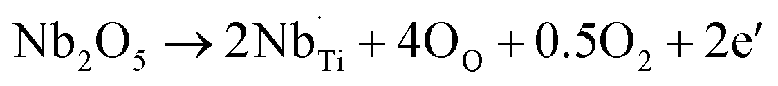 ), but also to the formation of oxygen vacancies (
 ), and subsequent reduction of some Ti4+ to Ti3+.62,63 The PTCR effect weakens after Nb doping, but a significant conductivity drop of ≥2.01 orders of magnitude above the Curie temperature was retained as the oxygen vacancies can act as electron traps at the grain boundary.60 The BaTiO3 sample with 0.3 at% La doping exhibits the highest conductivity with a significant PTCR effect among the La-doped BaTiO3 samples, and the BaTiO3 samples with Nb doping amounts between 0.2 and 0.6 at% show similarly improved conductivities and significant PTCR effects. Therefore, 0.3 at% La and 0.2 to 0.6 at% Nb doping amounts have been selected for La–Nb-co-doped BaTiO3 samples. As shown in Fig. 3c, the conductivity and PTCR effect of BaTiO3 have been affected by both La and Nb doping, and the BaTiO3 with 0.3 at% La and 0.2 at% Nb co-doping exhibits the highest conductivity of 2.71 × 10⁻³ S cm−1 at room temperature with a significant PTCR effect of 2.23 orders of magnitude above the Curie temperature.
3.2. Application of PTCR films for thermal protection of lithium-ion battery materials
The La and Nb co-doped BaTiO3 composition with the best combination of conductivity and PTCR effect (BTO-L3N2) was selected for battery testing. A co-doped BaTiO3 film (thickness ∼200 μm) was placed between the cathode and the spacer (in coin cells) or between the cathode and the electrode plunger (in Swagelok cells) of a battery with a LiFePO4 cathode and a Li anode. The effects of the inorganic BaTiO3-based PTCR film on the thermal and electrochemical performances of the battery were evaluated by cyclic voltammetry, galvanostatic charge/discharge and electrochemical impedance spectroscopy at different temperatures.At room temperature, the LiFePO4 half cells with and without the film exhibit nearly identical cyclic voltammetry curves with redox peaks at 3.26 V and 3.66 V as shown in Fig. 4a, which indicates that the PTCR film had no adverse effect on the performance of the battery, thanks to its high electrical conductivity and good chemical stability. This was confirmed by galvanostatic charge/discharge experiments at 0.1C (Fig. 4b), which show the same specific capacities of 153 mA h g−1 and discharge plateaus at 3.41 V, for the battery with and without the film. The combination of sufficiently high room temperature conductivity and low film thickness results in a negligible ohmic drop in the batteries operated at room temperature (estimation set out in ESI†), which explains why the battery can work in the presence of the PTCR film.
 | ||
| Fig. 4 (a) Cyclic voltammetry at scan rate of 0.1 mV s−1 and (b) 0.1C galvanostatic charge/discharge plots of LiFePO4 half cells with and without the PTCR film at 25 °C; (c) 0.1C galvanostatic charge/discharge plots and (d) electrochemical impedance spectroscopy of batteries with and without the PTCR film at 25 °C and elevated temperatures of 135 °C and 150 °C. | ||
When the temperature was increased to 135 °C, the battery without the PTCR film reached the maximum pre-set capacity of 170 mA h g−1 on charge, followed by discharge with a high discharge capacity of 138 mA h g−1 and a flat discharge plateau of around 3.4 V (Fig. 4c). These results show that, without the PTCR film, the reactions of lithium insertion and extraction proceed without control. In contrast, the battery with the PTCR film showed, at 135 °C, a remarkable increase/drop in charge/discharge voltage, which attained values of ca. 3.65 V and 3.05 V, and delivered a dramatically reduced charge/discharge capacity of 54 and 19 mA h g−1, respectively, thus showing that the current flow was effectively blocked. When the temperature was further raised to 150 °C, the charge and discharge voltage of the battery with the PTCR film quickly reached the pre-set upper and lower limits of 4.1 V and 2.5 V, respectively, delivering practically no charge/discharge capacity. This was attributed to the PTCR effect of the La and Nb co-doped BaTiO3 film, which was insulating above 135 °C. The decrease in conductivity of the PTCR film at high temperature produces a significant ohmic drop (see ESI†), which explains the variations in charge/discharge voltage observed experimentally. Notably, the batteries exposed to these drastic thermal treatments could recover a reasonable capacity when the temperature was changed back to 25 °C (ESI, Fig. S4†), indicating a good reversibility and electrochemical stability of the battery with the PTCR film.
The PTCR effect of the La and Nb co-doped BaTiO3 film can also be directly evidenced by the temperature dependence of the electrochemical impedance spectra (EIS) of the battery. As shown in Fig. 4d, batteries both with and without the PTCR film presented similar EIS spectra at 25 °C, with a semicircle at high frequency and a tail at low frequency, usually ascribed to the charge transfer or contact resistance and Warburg impedance of Li-ion diffusion, respectively. As the temperature increased to 135 °C, the battery without the PTCR film exhibited a slightly larger semicircle, which suggested a small rise of the charge transfer resistance in the battery. This could be tentatively ascribed to electrolyte degradation at high temperature, with a thicker SEI layer formed on the surface of the lithium electrode. However, the battery with the PTCR film showed a considerably enlarged semicircle, which indicated a large increase of the charge transfer or contact resistance in the battery, ascribable to the dramatic increase in resistivity of the PTCR film.
3.3. Preservation of the electrochemical performance of lithium-ion battery materials with PTCR films
The incorporation of the PTCR film for thermal protection should not produce any adverse influence on the electrochemical performance of the batteries in the operating temperature range, either at ambient or at the elevated working temperatures required for many applications.First, the cycling performance of LiFePO4 half cells with and without the PTCR film were compared at the standard ambient temperature of 25 °C, at current rates of 0.1C and 1C. Fig. 5a and b shows that the batteries with and without the PTCR film delivered essentially the same initial discharge capacities of ∼153 and ∼130 mA h g−1 at 0.1C and 1C, respectively, and excellent capacity retentions of ≥96.8% and 105.7% after 50 cycles. For batteries cycled at 1C rate, the increased capacity after 50 cycles can be attributed to a slow penetration of electrolyte into the electrode materials during cycling that enables a better contact between active materials and the electrolyte.64 Fig. S5a and b (ESI†) shows that the coulombic efficiencies of the batteries with and without the PTCR film are essentially the same, thus demonstrating that the PTCR film does not induce side reactions. Fig. S6 (ESI†) shows that the differences observed in the cells with and without PTCR film are smaller than the reproducibility of the experiments.
 | ||
| Fig. 5 Electrochemical performances of LiFePO4 half cells with and without the PTCR film: galvanostatic cycling performances and charge/discharge plots (insets) at a current rate of (a) 0.1C and (b) 1C at 25 °C; (c) the specific discharge capacities at various sequential rates from 0.1C to 5C at 25 °C; (d) galvanostatic cycling performances and charge/discharge plots (inset) at a current rate of 1C at 45 °C. | ||
The rate capabilities of the batteries with and without the PTCR film at 25 °C were also found to be consistent at various sequential current rates from 0.1C to 5C (Fig. 5c and ESI, S5e†). The battery with the PTCR film exhibited specific discharge capacities of 154, 152, 148, 141, 129 and 68 mA h g−1 at 0.1C, 0.2C, 0.5C, 1C, 2C and 5C, respectively, and the discharge capacity was fully recovered when the cycling rate was switched back to 0.1C, indicating that, along with a good rate capability, the battery with the PTCR film possesses a high reversibility and electrochemical stability. Longer cycling studies were conducted at 0.5C rate for 80 cycles (ESI, Fig. S5c and d†), showing a high capacity retention of ≥98.5% over the first 60 cycles, albeit a drop in capacity was observed in further cycling, which are attributed to instabilities/reactivity of the lithium metal counter electrode during continuous cycling at high current densities (ca. 1 mA cm−2 in the experiments in ESI, Fig. S5c and d†).65,66
The cycling performance of batteries with and without the PTCR film were also studied at an elevated working temperature of 45 °C, and these measurements were done at a 1C rate to also evaluate the power capability. The batteries with and without the PTCR film exhibited nearly identical electrochemical behaviour with voltage plateaus of ∼3.52 V at charge and ∼3.34 V at discharge (inset in Fig. 5d). Both batteries delivered initial discharge capacity of ≥131 mA h g−1 at 1C rate, and capacity retention of ≥102.7% after 50 cycles (Fig. 5d), with high coulombic efficiency of ≥99% (ESI, Fig. S5f†).
To further demonstrate the absence of adverse effects from the incorporation of the PTCR films, additional experiments were done with LiCoO2 electrodes, which is one of the most commonly used cathode materials in lithium-ion batteries.67–69 The cycling performance of LiCoO2 half cells with and without the PTCR film at ambient temperature were compared at a current rate of 0.1C. Both batteries exhibited similar initial charge/discharge plots (inset in ESI, Fig. S7†), delivering essentially the same initial specific discharge capacities of ∼157 mA h g−1 at 0.1C and capacity retentions of ≥94.3% after 20 cycles (ESI, Fig. S7†).
In summary, the BaTiO3-based PTCR film had no adverse effect on the battery's electrochemical performance at ambient temperature or 45 °C, which is a common operational temperature range required for battery applications. The absence of loss of capacity or rate capability under operational battery conditions is ascribed to the high electrical conductivity of the PTCR film at the relevant temperatures, as well as its high chemical stability. Additional measurements were also performed with the PTCR film acting as a cathode (thus substituting LiFePO4 or LiCoO2 in the Li-half cells). As expected, the PTCR film delivers very small capacity in galvanostatic cycling and very low currents in cyclic voltammetry experiments (ESI, Fig. S8†), demonstrating that all the capacity measured in LiFePO4 or LiCoO2 half cells with the doped BaTiO3 film can be attributed to the LiFePO4 or LiCoO2 response. Having validated the suitability of the incorporation of a BaTiO3-based film without adverse effects in the battery performance under operating conditions, the next section describes the evaluation of the effect of the PTCR film in batteries under abuse conditions.
3.4. Improving the safety of lithium-ion batteries under abuse conditions with PTCR films
The effectiveness of the inorganic BaTiO3-based PTCR film in improving the safety of practical batteries was evaluated by assembling CR2032 full coin cells with LiFePO4 or LiCoO2 as cathode and graphite as anode (LiFePO4-graphite or LiCoO2-graphite cell), which were then tested under abuse conditions of overcharge and overheating.For the overcharge tests, the LiFePO4-graphite cells with and without the PTCR film were charged at a constant current of 0.4C, until the cell either reached 180% SOC or exceeded a 10 V potential limit. As shown in Fig. 6a, in stage I, during the normal charging process (before 100% SOC), the cells operated as normal, with Li-ions extracted from the LiFePO4 cathode and intercalated into the graphite anode. After the cells were fully charged (≥100% SOC, stage II), the cathode was fully delithiated and no more Li-ions could be extracted, so the voltage of the battery increased until overcharge reactions initiated, at around 4.7 V, and the continuation of the overcharge reactions produced a voltage plateau of around 5.7 V. The behaviour of the batteries with and without the PTCR film is similar in these two stages and it is also in good agreement with previous studies on overcharge tests of lithium-ion batteries.70–74
 | ||
| Fig. 6 (a) Voltage changes during overcharging tests for LiFePO4-graphite cells with and without the BTO-L3N2 PTCR film; (b) temperature dependence of resistivity (PTCR effect) for the BTO-L3N2 film; (c) voltage and temperature changes during heating tests at 150 °C for LiFePO4-graphite cells with and without the BTO-L3N2 PTCR film; (d) distribution diagram of the survival time of cells during heating tests, insets are the cells without (left) and with (right) the PTCR film, photographs being taken after heating tests. | ||
In the following stage III of the overcharge process (Fig. 6a), the cells with and without the PTCR film showed totally different overcharge behaviours. The cell without the PTCR film experienced rapid voltage fluctuations between 5.7 and 6.6 V. Eventually the cell voltage suddenly increased to 13 V at 150% SOC, and it was observed that the cell had swelled. The overcharge tests usually produce degradation reactions such as the decomposition of the electrolyte, SEI destruction, etc., and some of these reactions produced flammable gases and heat, leading to cell swelling and more accelerated degradation.3,23,75–78 In contrast, the cell with the PTCR film maintained a stable voltage of about 5.7 V and the overcharge test continued until the set limit of 180% SOC was reached. Similar phenomena have been observed for the LiCoO2-graphite cells (ESI, Fig. S9†), which failed when reaching 157% SOC during overcharge tests, while the cell with the PTCR film remained stable up to 180% SOC. Clearly, the inorganic PTCR film enabled a stronger tolerance to overcharging.
The overcharge protection produced by the PTCR film can be ascribed to the increase in its resistivity with temperature, as shown in Fig. 6b and ESI, S10.† The La and Nb co-doped BaTiO3 film exhibits a low resistivity of 3.69 × 10² Ω cm at room temperature, and the resistivity starts to rise slowly from 75 °C, then increases rapidly from around 115 °C, reaching a high value of 6.33 × 10⁴ Ω cm at 135 °C. As schematically illustrated in Fig. 7, as the inner pressure and temperature of the battery increases during the overcharging process, due to the heat generated from the side reactions like electrolyte decomposition, the thermal protection mechanism of the PTCR film would be triggered. Its resistance would start to increase, which would, in turn, slow down the cell reactions and restrain heat generation, thus maintaining the battery at a relatively low temperature, and keeping the battery stable.
 | ||
| Fig. 7 Schematic illustrations of the electrochemical and thermal behaviours of LiFePO4-graphite and LiCoO2-graphite cells with and without the PTCR film under abuse conditions of overcharging and overheating. | ||
The effectiveness of the PTCR film in enhancing battery safety was evaluated also by performing a heating test, which is often considered the strictest criterion for the safety evaluation of lithium-ion batteries.23,24 The fully charged LiFePO4-graphite cells with and without the PTCR film were heated to 150 °C at 4 °C min−1, and kept at 150 °C for 60 min, with the voltage and the temperature of the batteries being recorded. As shown in Fig. 6c, both cells showed a decrease of the open circuit voltage from 4.1 V to around 3.3 V as the temperature increased to 150 °C. The battery without the PTCR film could only sustain the heating test at 150 °C for ∼36 min, and suddenly failed with the voltage dropping to 0 V. Similar experiments have shown that such drastic decrease of the cell voltage is due to an internal short circuit of the battery as a result of the shrinking and melting of the separator at high temperature, which can lead to a dramatic rise of the cell temperature and fire.24 In contrast, the battery with the PTCR film remained stable, with an open circuit voltage of around 3.3 V after the temperature reached 150 °C, and sustained the whole heating test, demonstrating safe behaviour. While the cell without the PTCR film showed visible failure of the coin cell seal due to excess pressure after the heating test, the cell with the PTCR film looked unaltered (inset in Fig. 6d). The enhanced stability of the cell with the PTCR film can be attributed, again, to the increase in resistivity with temperature. At the very high temperatures, the PTCR film acts as an insulating layer and, thus, inhibits the electron transport in the battery. The higher resistance of the cell with the PTCR film delayed or hampered the internal short circuit of the cell (schematically illustrated in Fig. 7) and the heat-generating rate of the battery was greatly decreased, thus preventing thermal runaway. To confirm the reproducibility of the protection mechanism offered by the inorganic PTCR film, further heating tests were conducted on ten LiFePO4-graphite full cells with and without the La and Nb co-doped BaTiO3 film (five each). As displayed in Fig. 6d and ESI, S11,† the five batteries without the PTCR films failed the heating test at 150 °C, showing a tolerating duration in the range 28–43 min. Meanwhile, the five batteries with the PTCR films remained stable for the full 60 min, demonstrating the effectiveness of the BaTiO3 film in preventing thermal runaway. Similar phenomena were observed from heating tests performed on LiCoO2-graphite cells (ESI, Fig. S12†). The fully charged battery without the PTCR film could only sustain the heating test for ∼32 min after the temperature reached 150 °C, and suddenly failed with the voltage dropping to 0 V. In contrast, the battery with the PTCR film remained stable, with an open circuit voltage maintained at around 3.7 V at 150 °C, and sustained the whole heating test, demonstrating safe behaviour.
As schematically illustrated in Fig. 7, under abuse conditions of overheating and overcharging, the conventional lithium-ion batteries without the PTCR film would generate a large amount of flammable gases and Joule heat due to the internal short circuit of the cell or side reactions like electrolyte decomposition, leading to uncontrollable increases of the inner pressure and temperature of the battery, thus accelerating the exothermic reactions in the battery, and resulting in a thermal runaway. However, the battery with the PTCR film showed a high thermal stability and good safety performance under abuse conditions. This was attributed to the PTCR effect of the La and Nb co-doped BaTiO3 film, which acted as an insulating layer in the cell at high temperature, inhibiting the electron transport in the battery and restraining the cell reactions and heat generation, thus protecting the cell from thermal runaway. The enhanced safety of the batteries with the PTCR film is particularly important for applications such as electric vehicles, in which it is critical that the unsafe behaviour of one of the cells (e.g. sudden temperature rise, drastic voltage increase or decrease) is not transmitted to the battery pack.79–82 Our results show that the inorganic BaTiO3-based PTCR film effectively prevents unsafe voltage/temperature jumps of the batteries under abuse conditions, thus providing an efficient battery protection strategy.
4. Conclusion
We have developed a La and Nb co-doped BaTiO3 film showing a good room temperature conductivity and significant PTCR effect to be employed as thermal protection layer in lithium-ion batteries. The PTCR film was incorporated into the battery system, acting as an insulating layer at high temperature and inhibiting the electron transport in the battery, thus restraining the cell reactions and heat generation and effectively preventing thermal runaway. Lithium-ion batteries containing the BaTiO3-based PTCR film exhibited not only excellent electrochemical performance at ambient temperature but also a strong tolerance to overheating and overcharging. Our results provide the first example of an inorganic PTCR system enabling efficient thermal stability and safety performance under abuse conditions and without any adverse implications for the electrochemical performance within the working temperature range. Importantly, this self-standing inorganic PTCR film with high chemical stability is not lithium-specific, it can be easily applied in other battery systems for preventing thermal runaway.Conflicts of interest
There are no conflicts to declare.Acknowledgements
The authors thank EPSRC for support under the Industrial Strategy Challenge Fund (EP/R021295/1) and for an early career fellowship to NGA (EP/N024303/1). The raw data associated with figures in this manuscript and the ESI can be found at https://doi.org/10.5258/SOTON/D2206.Notes and references
- P. Sun, R. Bisschop, H. Niu and X. Huang, Fire Technol., 2020, 56, 1361–1410 CrossRef.
- X. Feng, M. Ouyang, X. Liu, L. Lu, Y. Xia and X. He, Energy Storage Mater., 2018, 10, 246–267 CrossRef.
- Q. Wang, P. Ping, X. Zhao, G. Chu, J. Sun and C. Chen, J. Power Sources, 2012, 208, 210–224 CrossRef CAS.
- X. Feng, D. Ren, X. He and M. Ouyang, Joule, 2020, 4, 743–770 CrossRef CAS.
- T. M. Bandhauer, S. Garimella and T. F. Fuller, J. Electrochem. Soc., 2011, 158, R1–R25 CrossRef CAS.
- D. Doughty and E. P. Roth, Electrochem. Soc. Interface, 2012, 21, 37–44 CAS.
- Q. Wang, B. Mao, S. I. Stoliarov and J. Sun, Prog. Energy Combust. Sci., 2019, 73, 95–131 CrossRef.
- P. G. Balakrishnan, R. Ramesh and T. Prem Kumar, J. Power Sources, 2006, 155, 401–414 CrossRef CAS.
- X. Jiang, L. Xiao, X. Ai, H. Yang and Y. Cao, J. Mater. Chem. A, 2017, 5, 23238–23242 RSC.
- M. Baginska, B. J. Blaiszik, T. Rajh, N. R. Sottos and S. R. White, J. Power Sources, 2014, 269, 735–739 CrossRef CAS.
- M. Baginska, B. J. Blaiszik, R. J. Merriman, N. R. Sottos, J. S. Moore and S. R. White, Adv. Energy Mater., 2012, 2, 583–590 CrossRef CAS.
- Y. Shi, H. Ha, A. Al-Sudani, C. J. Ellison and G. Yu, Adv. Mater., 2016, 28, 7921–7928 CrossRef CAS PubMed.
- H. Yang, Z. Liu, B. K. Chandran, J. Deng, J. Yu, D. Qi, W. Li, Y. Tang, C. Zhang and X. Chen, Adv. Mater., 2015, 27, 5593–5598 CrossRef CAS PubMed.
- L. Xia, D. Wang, H. Yang, Y. Cao and X. Ai, Electrochem. Commun., 2012, 25, 98–100 CrossRef CAS.
- H. Li, X. Zhang, C. Zhang, Y. Cao, H. Yang, X. Ai and F. Zhong, Energy Technol., 2020, 8, 2000365 CrossRef CAS.
- M. Wang, A. V. Le, D. J. Noelle, Y. Shi, Y. S. Meng and Y. Qiao, J. Power Sources, 2017, 349, 84–93 CrossRef CAS.
- L. Li, C. Xu, R. Chang, C. Yang, C. Jia, L. Wang, J. Song, Z. Li, F. Zhang, B. Fang, X. Wei, H. Wang, Q. Wu, Z. Chen, X. He, X. Feng, H. Wu and M. Ouyang, Energy Storage Mater., 2021, 40, 329–336 CrossRef.
- Q. Yuan, F. Zhao, W. Wang, Y. Zhao, Z. Liang and D. Yan, Electrochim. Acta, 2015, 178, 682–688 CrossRef CAS.
- D. P. Finegan, E. Darcy, M. Keyser, B. Tjaden, T. M. M. Heenan, R. Jervis, J. J. Bailey, R. Malik, N. T. Vo, O. V. Magdysyuk, R. Atwood, M. Drakopoulos, M. DiMichiel, A. Rack, G. Hinds, D. J. L. Brett and P. R. Shearing, Energy Environ. Sci., 2017, 10, 1377–1388 RSC.
- E. P. Roth, D. H. Doughty and D. L. Pile, J. Power Sources, 2007, 174, 579–583 CrossRef CAS.
- K. Xu, Chem. Rev., 2014, 114, 11503–11618 CrossRef CAS PubMed.
- D. Aurbach, Y. Talyosef, B. Markovsky, E. Markevich, E. Zinigrad, L. Asraf, J. S. Gnanaraj and H.-J. Kim, Electrochim. Acta, 2004, 50, 247–254 CrossRef CAS.
- H. Li, F. Wang, C. Zhang, W. Ji, J. Qian, Y. Cao, H. Yang and X. Ai, Energy Storage Mater., 2019, 17, 275–283 CrossRef.
- W. Ji, F. Wang, D. Liu, J. Qian, Y. Cao, Z. Chen, H. Yang and X. Ai, J. Mater. Chem. A, 2016, 4, 11239–11246 RSC.
- H. Zhong, C. Kong, H. Zhan, C. Zhan and Y. Zhou, J. Power Sources, 2012, 216, 273–280 CrossRef CAS.
- L. Xia, L. Zhu, H. Zhang and X. Ai, Chin. Sci. Bull., 2012, 57, 4205–4209 CrossRef CAS.
- M. Li, Y. Shi, H. Gao and Z. Chen, Adv. Funct. Mater., 2020, 30, 1910328 CrossRef CAS.
- Z. Chen, P.-C. Hsu, J. Lopez, Y. Li, J. W. F. To, N. Liu, C. Wang, S. C. Andrews, J. Liu, Y. Cui and Z. Bao, Nat. Energy, 2016, 1, 1–8 Search PubMed.
- L. Xia, S.-L. Li, X.-P. Ai, H.-X. Yang and Y.-L. Cao, Energy Environ. Sci., 2011, 4, 2845–2848 RSC.
- H. Zhang, J. Pang, X. Ai, Y. Cao, H. Yang and S. Lu, Electrochim. Acta, 2016, 187, 173–178 CrossRef CAS.
- S.-S. Ryu, H.-T. Kim, H. J. Kim and S. Kim, J. Ceram. Soc. Jpn., 2009, 117, 811–814 CrossRef CAS.
- P. Ctibor, H. Ageorges, J. Sedlacek and R. Ctvrtlik, Ceram. Int., 2010, 36, 2155–2162 CrossRef CAS.
- H. Y. Sun, Y. Takeda, N. Imanishi, O. Yamamoto and H.-J. Sohn, J. Electrochem. Soc., 2000, 147, 2462–2467 CrossRef CAS.
- M. Acosta, R. Detsch, A. Grünewald, V. Rojas, J. Schultheiß, A. Wajda, R. W. Stark, S. Narayan, M. Sitarz, J. Koruza and A. R. Boccaccini, J. Am. Ceram. Soc., 2018, 101, 440–449 CrossRef CAS.
- G. Wypych, Handbook of Fillers, ChemTec Publishing, 2016 Search PubMed.
- Y. L. Chen and S. F. Yang, Adv. Appl. Ceram., 2013, 110, 257–269 CrossRef.
- W. Heywang, J. Am. Ceram. Soc., 1964, 47, 484–490 CrossRef CAS.
- G. H. Jonker, Solid-State Electron., 1964, 7, 895–903 CrossRef CAS.
- B. Huybrechts, K. Ishizaki and M. Takata, J. Mater. Sci., 1995, 30, 2463–2474 CrossRef CAS.
- K. M. Holsgrove, D. M. Kepaptsoglou, A. M. Douglas, Q. M. Ramasse, E. Prestat, S. J. Haigh, M. B. Ward, A. Kumar, J. M. Gregg and M. Arredondo, APL Mater., 2017, 5, 066105 CrossRef.
- W. Preis and W. Sitte, J. Electroceram., 2014, 34, 185–206 CrossRef.
- R. D. Roseman and N. Mukherjee, J. Electroceram., 2003, 10, 117–135 CrossRef CAS.
- A. Larson, R. Von Dreele, L. Finger, M. Kroeker and B. Toby, J. Appl. Crystallogr., 2001, 34, 210–213 CrossRef.
- R. Kumari, P. K. Kulriya, S. Mishra, V. Kotari, S. N. Achary, A. K. Tyagi and D. K. Avasthi, J. Am. Ceram. Soc., 2017, 100, 4263–4269 CrossRef CAS.
- M. Yang, C. Wang, Z. Peng and X. Fu, J. Mater. Sci.: Mater. Electron., 2017, 28, 10589–10595 CrossRef CAS.
- R. D. Shannon, Acta Crystallogr., 1976, A32, 751–767 CrossRef CAS.
- M. B. Smith, K. Page, T. Siegrist, P. L. Redmond, E. C. Walter, R. Seshadri, L. E. Brus and M. L. Steigerwald, J. Am. Chem. Soc., 2008, 130, 6955–6963 CrossRef CAS PubMed.
- B. D. Begg, K. S. Finnie and E. R. Vance, J. Am. Ceram. Soc., 1996, 79, 2666–2672 CrossRef CAS.
- M. M. Vijatović Petrović, J. D. Bobić, J. Banys and B. D. Stojanović, Mater. Res. Bull., 2013, 48, 3766–3772 CrossRef.
- M. El Marssi, F. Le Marrec, I. A. Lukyanchuk and M. G. Karkut, J. Appl. Phys., 2003, 94, 3307–3312 CrossRef CAS.
- Y. Shiratori, C. Pithan, J. Dornseiffer and R. Waser, J. Raman Spectrosc., 2007, 38, 1300–1306 CrossRef CAS.
- A. Mansuri, I. N. Bhatti, I. N. Bhatti and A. Mishra, J. Adv. Dielectr., 2018, 8, 1850024 CrossRef CAS.
- S. B. Desu, J. Am. Ceram. Soc., 1990, 73, 3398–3406 CrossRef CAS.
- Y.-M. Chiang and T. Takagi, J. Am. Ceram. Soc., 1992, 75, 2017–2019 CrossRef CAS.
- S. B. Desu, J. Am. Ceram. Soc., 1992, 75, 2020–2024 CrossRef CAS.
- S. B. Desu, J. Am. Ceram. Soc., 1990, 73, 3407–3415 CrossRef CAS.
- M. N. Rahaman and R. Manalert, J. Eur. Ceram. Soc., 1998, 18, 1063–1071 CrossRef CAS.
- B. Ertuğ, in Powder Metallurgy, ed. K. Kondoh, InTech, Rijeka, Croatia, 2012, ch. 4, pp. 73–98, DOI: DOI:10.5772/33930.
- F. D. Morrison, A. M. Coats, D. C. Sinclair and A. R. West, J. Electroceram., 2001, 6, 219–232 CrossRef CAS.
- H. Donnerberg and A. Birkholz, J. Phys.: Condens. Matter, 2000, 12, 8239–8247 CrossRef CAS.
- F. Si, B. Tang, Z. Fang and S. Zhang, Crystals, 2017, 7, 168 CrossRef.
- X. Cheng, D. Zhou, Q. Fu, S. Gong and D. Zhao, J. Mater. Sci.: Mater. Electron., 2012, 23, 2202–2209 CrossRef CAS.
- C. L. Freeman, J. A. Dawson, H.-R. Chen, L. Ben, J. H. Harding, F. D. Morrison, D. C. Sinclair and A. R. West, Adv. Funct. Mater., 2013, 23, 3925–3928 CrossRef CAS.
- R. Dominko, J. M. Goupil, M. Bele, M. Gaberscek, M. Remskar, D. Hanzel and J. Jamnik, J. Electrochem. Soc., 2005, 152, A858–A863 CrossRef CAS.
- A. B. Gunnarsdóttir, S. Vema, S. Menkin, L. E. Marbella and C. P. Grey, J. Mater. Chem. A, 2020, 8, 14975–14992 RSC.
- A. B. Gunnarsdottir, C. V. Amanchukwu, S. Menkin and C. P. Grey, J. Am. Chem. Soc., 2020, 142, 20814–20827 CrossRef CAS PubMed.
- J. W. Fergus, J. Power Sources, 2010, 195, 939–954 CrossRef CAS.
- M. Zhang, N. Garcia-Araez, A. L. Hector and J. R. Owen, J. Mater. Chem. A, 2017, 5, 2251–2260 RSC.
- M. Zhang, N. Garcia-Araez and A. L. Hector, J. Mater. Chem. A, 2018, 6, 14483–14517 RSC.
- D. Ouyang, M. Chen, J. Liu, R. Wei, J. Weng and J. Wang, RSC Adv., 2018, 8, 33414–33424 RSC.
- Y.-B. He, G.-W. Ling, Z.-Y. Tang, Q.-S. Song, Q.-H. Yang, W. Chen, W. Lv, Y.-J. Su and Q. Xu, J. Solid State Electrochem., 2009, 14, 751–756 CrossRef.
- S.-I. Tobishima and J.-I. Yamaki, J. Power Sources, 1999, 81–82, 882–886 CrossRef CAS.
- C. J. Wang, Y. L. Zhu, F. Gao, C. Qi, P. L. Zhao, Q. F. Meng, J. Y. Wang and Q. B. Wu, Int. J. Energy Res., 2020, 44, 5477–5487 CrossRef CAS.
- M. Ouyang, D. Ren, L. Lu, J. Li, X. Feng, X. Han and G. Liu, J. Power Sources, 2015, 279, 626–635 CrossRef CAS.
- T. Ohsaki, T. Kishi, T. Kuboki, N. Takami, N. Shimura, Y. Sato, M. Sekino and A. Satoh, J. Power Sources, 2005, 146, 97–100 CrossRef CAS.
- K. Kumai, H. Miyashiro, Y. Kobayashi, K. Takei and R. Ishikawa, J. Power Sources, 1999, 81–82, 715–719 CrossRef CAS.
- D. P. Finegan, E. Darcy, M. Keyser, B. Tjaden, T. M. M. Heenan, R. Jervis, J. J. Bailey, N. T. Vo, O. V. Magdysyuk, M. Drakopoulos, M. D. Michiel, A. Rack, G. Hinds, D. J. L. Brett and P. R. Shearing, Adv. Sci., 2018, 5, 1700369 CrossRef PubMed.
- Y. Fernandes, A. Bry and S. de Persis, J. Power Sources, 2018, 389, 106–119 CrossRef CAS.
- R. M. Spotnitz, J. Weaver, G. Yeduvaka, D. H. Doughty and E. P. Roth, J. Power Sources, 2007, 163, 1080–1086 CrossRef CAS.
- C. F. Lopez, J. A. Jeevarajan and P. P. Mukherjee, J. Electrochem. Soc., 2015, 162, A1905–A1915 CrossRef CAS.
- J. Lamb, C. J. Orendorff, L. A. M. Steele and S. W. Spangler, J. Power Sources, 2015, 283, 517–523 CrossRef CAS.
- P. Huang, P. Ping, K. Li, H. Chen, Q. Wang, J. Wen and J. Sun, Appl. Energy, 2016, 183, 659–673 CrossRef CAS.
Footnote |
| † Electronic supplementary information (ESI) available. See https://doi.org/10.1039/d2ta00998f |
| This journal is © The Royal Society of Chemistry 2022 |