 Open Access Article
Pd(/Fe3O4)-on-ZIFs: nanoparticle deposition on (nano-)MOFs from ionic liquids†
Olga
Koikolainen
 a,
Linda
Sondermann
a,
Stefan
Roitsch
b,
Ilka
Simon
a,
Linda
Sondermann
a,
Stefan
Roitsch
b,
Ilka
Simon
 a,
Dennis
Dietrich
a,
Vasily
Gvilava
a,
Juri
Barthel
a,
Dennis
Dietrich
a,
Vasily
Gvilava
a,
Juri
Barthel
 c,
Jörg
Thomas
d,
Christoph
Janiak
 *a and
Ishtvan
Boldog
 *a
*a
aInstitut für Anorganische Chemie und Strukturchemie, Heinrich-Heine-Universität Düsseldorf, Universitätsstraße 1, 40225 Düsseldorf, Germany. E-mail: janiak@hhu.de; boldogi@hhu.de
bInstitut für Physikalische Chemie, Universität zu Köln, Luxemburger Str. 116, 50939 Köln, Germany
cGemeinschaftslabor für Elektronenmikroskopie RWTH-Aachen, Ernst Ruska-Centrum für Mikroskopie und Spektroskopie mit Elektronen, 52425 Jülich, Germany
dAbteilung Struktur und Nano-/Mikromechanik von Materialien Transmissionselektronenmikroskopie, Max-Planck-Institut für Eisenforschung GmbH, 40237 Düsseldorf, Germany
First published on 15th March 2022
Abstract
Well-defined spherical Pd-NPs (∼6–12 nm size, 4–17% wt content) were efficiently deposited on nano- or micro- (∼100–2500 nm) crystals of zeolite imidazolate frameworks (ZIFs) from different ionic liquids (ILs, typically 1-butyl-3-methylimidazolium bistriflimidate, [BMIm]NTf2) at 180–230 °C under microwave (MW) heating for 1–10 min. The firm, nearly exclusive on-surface deposition, proven by systematic analysis of TEM micrographs, is achieved via size-exclusion of the IL-solvated PdCl2 precursor. The one-pot high-quality NP deposition from partially stabilizing IL media leads to particularly well-defined metal nanoparticles-on-metal–organic frameworks, MNP-on-MOF(NP)s. They are contraposed to MNP@MOFs or non-specified MNP/MOFs, and are viewed as an extension of MNPs from ionic liquids, securing MNP-agglomeration protection after removal of the IL and reversible redispersion, and offering the functionality of the porous support. Pd-on-ZIF-8-NP (R = Me substituent of the azole ligand) demonstrated the highest stability and morphological quality, while the ZIF-90 analogues with the same sod topology (R = COOH, CHO, CH2CH2NH2) or the triazolate MAF-66 (R = NH2) with dia topology showed lesser stability (particularly for R = COOH and CHO). Ferromagnetic Pd/Fe3O4- and Fe3O4/Pd-on-ZIF-8-NP, ZIF-90-NH2(-NP), and MAF-66 composites with nanoparticulated Fe3O4 (5–13 nm size, 5–22%wt content) demonstrate the feasibility of sequential NP deposition of varied nature. The Pd-on-ZIF composites demonstrated high catalytic activity in the reduction of 4-nitrophenol to 4-aminophenol by NaBH4 in water (TOF 0.38–4.10 vs. 0.088 s−1 for 10%wt Pd/C; amino-functionalization and the presence of Fe3O4 are a major and a minor factor, respectively). The reduction of the same substrate with H2 in apolar media was much slower for the composite catalysts compared to Pd/C (10%wt) due to possible poisoning by the residual IL.
Introduction
Metal nanoparticle synthesis from ionic liquids and stabilization issues
Metal nanoparticles (NPs; 1–100 nm size by definition) and metal nanostructures represent an important class of functional materials, demonstrating prominent, primarily plasmonic, optical (quantum dots), electronic,1 electrochemical,2,3 and magnetic properties4 as well as offering special catalytic5 capabilities due to enhanced active-sites associated with high surface energy. The most promising applications, in which the metal NP is a functional core of a composite, include light emission6 and energy conversion,7,8 various types of (bio)sensing9–11 (primarily plasmonics-based, SPR/SERS), (bio)imaging12 and (photo)therapy and addressed drug-delivery.13The synthesis of metal-NPs (M-NPs and MOx-NPs, respectively) from ionic liquids (ILs) via controlled decomposition or reduction of molecular precursors, such as metal carbonyls or amidinates, is one of the most efficient methods of preparation of very small metal nanoparticles (Rh, Pd, Pt, Ir, Fe, Ru, Co, Au, Ag, Cu, Ni, and others), with sizes typically in the range of 2–10 nm.14,15 The NP colloids in ILs are particularly well stabilized, which is typically explained by the formation of a robust double electric layer in the ionic medium, in accordance with DLVO theory, as well as by the presence of species acting as capping ligands in some cases.
The NP-IL colloids could be used as efficient catalytic systems16 (particularly for hydrogenations, e.g. of arenes17), but their scope is somewhat limited. The colloids could be used as a constituent of biphasic IL–organic reaction media, although not without compatibility limitations. The separation of the NPs from the IL nearly automatically means coagulation issues. It is worth noting that ILs are quite expensive as well as occasionally toxic, and hence their avoidance in the reaction medium is an evident improvement/innovation target. Possible improvements are to use (nanoparticle-)supported ionic liquid phase catalysts18 and even deposition of suspensions onto inorganic supports19 (including porous supports20), which still essentially rely on the presence of ILs in the final materials.
NP immobilization on (macro- vs. nano)particulated (micro)porous supports
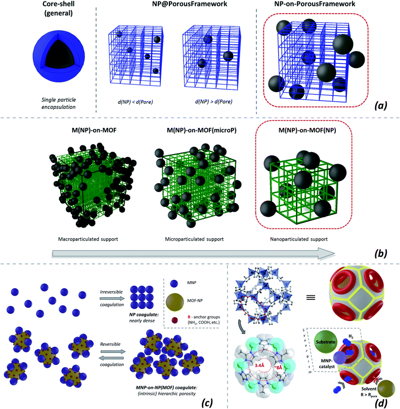
The immobilization of nanoparticles on various macroscopic supports is an established approach,20 aiming for stable, functional, and easily separable materials. Non-porous macroparticulated/monolithic supports allow the immobilized nanoparticulated catalyst to be used economically but decrease the advantage of the neat NPs in terms of high specific surface area. The problem is addressed by porous macroscopic supports,21 like active carbon or zeolites (the resulting materials include NP@host composites22 (Fig. 1b, center) where the nanoparticles are grown in the pores of the (crystalline) host and are larger than the pore-entrances).A possible alternative is to use micro- or even nanoparticulated supports instead of macroparticulated ones. The size of the support particles could be somewhat larger than the size of the supported NPs, yet small enough to grant significant surface areas. The optimized support-particle sizes grant resilience against aggregation/coagulation, potentially allowing the redispersion of the particles upon reaching a certain size (Fig. 1c, center).
There is a fine difference between deposition types when the support is microporous. In this case two possibilities could be envisaged (Fig. 1a): NP@support and/or core–shell particles, i.e. encapsulation within the support particle, and NP-on-support, i.e. localization on the external surface of the support (for non-porous supports only the latter case is valid). The difference is subtle and topological in essence: in the first case, the boundaries of a composite's particle (pore surfaces are not counted as borders) are represented only by the support, while in the second case the particle boundary is represented by both phases.
Direct and ‘inverse’ size-exclusion effect for NP ‘@’ and ‘-on-’ microporous supports (MPS) and the effect of nanoparticulation
The properties of the NP@MPS and NP-on-MPS (Fig. 1c) are close if the support is permeable to all the components of the surrounding medium. However, the two types of materials behave differently when there is a size-exclusion effect for some of the reactants. The size-exclusion regarding the substrate and products is evident and sought after in the NP@MPS case. The ‘inverse’ possibility of locking out the inner part of a microporous support in the NP-on-MPS case is a niche possibility, which could still also be potentially interesting in the role of ‘concentrator’ containers for catalysis and sensing (Fig. 1d).Nanoparticulated NP-on-MPS could be differentiated as an interesting possibility, which retains the high specific surface area of the deposited nanoparticles. Neat and well-formed nanoparticulated NP-on-MPS is an interesting target for optimization, being also a precursor for more complex composite materials.
MNP-on-ZIF(-NP) vs. MNP@ZIFs
Metal–organic frameworks (MOFs) also known as porous coordination polymers/networks (PCPs/PCNs) represent a class of generally crystalline materials capable of demonstrating extremely high surface areas exceeding 6 × 10³ m2 g−1 and marked by particularly high structural and functional tunability.23,24 MOFs25 and MOF-based composites26 are interesting in the context of applications relying on or benefitting from high- or specialized-porosity characteristics.27,28 Promising applications include but are not limited to gas storage and separation,29 catalysis,30–32 sensorics,33 electrochemical energy storage,34 and drug delivery.35The actively researched MOF-based nanomaterials36 are often derived from nanoparticulated MOFs (nanoMOFs or MOFNPs).37 The nanoparticulation of MOFs could be controlled under mild conditions due to the lability of the coordination bonding, which is an advantage in regard to a bottom-up synthesis (cf. with nanoparticulated zeolites, which are a tougher target).
The NP@MOF composites (typically non-nanoparticulated) were actively researched during the last decade.26,38,39 The protected encapsulated functional NPs (Fig. 1a, center) are actively researched for size-exclusive catalysis, typically in catalytic hydrogenations, but also condensation and coupling.40 The support particle size in NP@MOF materials is rarely considered a parameter for variation in contrast to the pore-sizes.
Zeolitic imidazolate frameworks (ZIFs), an important MOF-class, appear to be an excellent choice for the synthesis of the special MNP-on-(nano)MPS materials in a neat form due to the following reasons:
(a) A structural prevalence of large spherical pores with relatively small entrances;
(b) Significant hydrolytic stability compared to other MOF materials;41
(c) Simple tunability of the surface nature and pore-entrance size via different 2-substitution of the imidazole ligands;
(d) Excellent nanoparticulability (i.e. the synthetic procedural simplicity to generate the material in nanoparticulate form and high responsivity of the product morphology to easily control parameters like temperature, concentration, and formation time).42 Importantly, the ZIF nanoparticles (50–100 nm) are generally redispersible, as demonstrated by DLS measurements.43
A large number of publications on MNP/ZIF composites exist, but often no clear differentiation between the MNP@ZIF vs. MNP-on-ZIF deposition is drawn. When a certain morphological type is targeted, it is mostly the MNP@MOF encapsulation of MNPs in ZIFs. Dominant MNP@MOF formation is typically achieved by decomposing small apolar precursors loaded in the pores, e.g. in Pd@ZIF-8 where Pd(acac)2 (ref. 44) or Pd(C3H5)(C5H5)45 are used as precursors, Au@ZIF-8 with Me2Au(acac),46 or Ni@ZIF-8 with Ni(cp)2.47 Alternatively, incipient wetness impregnation with subsequent evaporation of the solvent and reduction is used, but this method often leads to poorly defined NPs like in AgPd@ZIF-8 (ref. 48) and/or not only to ‘@’, but also to partial -on- deposition as in Cu/ZIF-8,49 Pd/ZIF-8,50 and Ru/ZIF-8;51 the -on- deposition, seemingly, might be stimulated by polar precursor solutions with low affinity for the inner pore surfaces. Finally, the morphologically best-defined core–shell M@ZIFs are typically obtained by growing the respective MOF shells around stabilized (typically by PVP) metal NPs39 as for Au@ZIF-8,52 (Au,Ag)@ZIF-8,53 Pt@ZIF-8,54–56 Pd@ZIF-8,57–61 Pd@ZIF-8 [hollow-spheres],62 (Pd,Au)@ZIF-8,63 Ru@ZIF-8 (ref. 64) and ZIF-8/Pd/ZIF-8 (ref. 65) composites,50 or via concurrent growth, e.g. as for M@ZIF-8 (M = Au, Pt, Pd), obtained by anodic crystallization of ZIF-8.66
Well-defined pure MNP-on-ZIF and particularly MNP-on-ZIF-NPs are less typically targeted. The existing approaches could be exemplified by a close example of the gold-coated M-on-MOF ‘Janus’ particles (MOF = ZIF-8, UiO-66, near NP-sized) prepared by casting of prefabricated metal particle colloids, and covering the composite particles by a gold layer67 (the latter step closes the surface). However, relatively numerous are the cases when the precise localization of the nanoparticles is not explicitly discussed, despite the TEM images perhaps indicating prevalent on-surface localization, e.g. in the early influential example of an Au,Ag/ZIF-8 composite68 (the reduction of the precursor in an aqueous medium, as in the last case, might increase the share of on-surface deposition, but it is not always evident, e.g. in Rh@ZIF-8![[thin space (1/6-em)]](https://www.rsc.org/images/entities/char_2009.gif) 69). Among such examples a significant share of MNP-on-ZIFs could be the Pd/ZIF-8 (PdCl2 as a precursor)70,71 or in the first step in the preparation of ZIF-8/(Pd or Au)/ZIF-8 core–shell particles using nearly nanoparticulated supports.65 Predominantly on-surface deposition could also be reached by use of grafting groups, like –COOH in Pd/modif-ZIF-8,72 by casting PVP-stabilized NPs,73 or, crudely, via simple grinding.46
69). Among such examples a significant share of MNP-on-ZIFs could be the Pd/ZIF-8 (PdCl2 as a precursor)70,71 or in the first step in the preparation of ZIF-8/(Pd or Au)/ZIF-8 core–shell particles using nearly nanoparticulated supports.65 Predominantly on-surface deposition could also be reached by use of grafting groups, like –COOH in Pd/modif-ZIF-8,72 by casting PVP-stabilized NPs,73 or, crudely, via simple grinding.46
MNP-on-ZIF-NPs could have particularly small pore-openings, suitable for accumulating small molecules, e.g. for H2 spillover,70 potentially enhancing hydrogenation catalysis. The on-surface localization removes size-selectivity and protection, but potentially allows viable catalyst materials, provided that the on-surface embedding is firm (Fig. 1d). The targeting of morphologically pure MNP-on-MOF(NP)s almost inevitably means a focus on structurally well-defined composite particles, relying on systematic electron microscopy investigation as the primary proof.
In this contribution, we report a series of Pd-on-(nano)ZIF (or Pd-on-ZIF-NP) composites and their ferromagnetic variants, Pd/Fe3O4-on-nanoZIF. The in situ formation and deposition of size-stabilized nanoparticles from ionic liquids at elevated temperatures was hypothesized as a general approach: in a narrow sense as a form of stabilization of IL-based MNPs with retention of high specific surface areas and in a broader sense as a method for preparation of well-formed MNP-on-[nanoparticulated microporous supports]. The assessment of the obtained materials as catalysts in the reduction of nitro-compounds and hydrogenation reactions depending on the type of support-functionalization was aimed at as well.
Experimental
Materials and methods
The nano- and microparticulated MOF supports were synthesized according to published procedures (ESI 4†). The natural propensity of ZIFs to form colloids in different solvents, particularly in alcohols, was employed. The majority of the ZIF-90-R derivatives were synthesized via postsynthetic transformations, performed according to the published procedures. The sizes of the MOF particles were determined in each case using TEM imaging.The ionic liquids for screening were used as delivered by commercial vendors (ESI 2.1†). The primary IL solvent used in this work, [BMIm]NTf2, was synthesized and thoroughly purified on a ∼100 g scale (ESI 3†).
The Fe3O4/Pd- and Pd/Fe3O4-on-MOF composites with two types of deposited NPs (the order of deposition corresponds to the order given in the composite name; see ESI 6, p. 34,† for the naming conventions) were prepared similarly, but in a single-pot two-step way. After treatment in the MW oven, the tube was returned to the glovebox, the second precursor (Fe2(CO)9 in the case of iron) was added, and the treatment in the oven was repeated. The further separation of the composite particles was performed similarly.
The morphology of the composite particles, the uniformity of the elemental distribution, and the average sizes of the constituents were determined by various electron microscopy methods, while the content of Fe and Pd was determined via AAS (the EDX based determinations corresponded sufficiently well to the AAS-based data in general, and in some cases evidently incorrect strong outliers were also detected due to limited sampling size; ESI 6†).
Results and discussion
MOF(-NP) supports
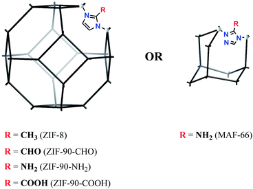
A representative set of ZIF-8 type materials (sod topology) and a MAF material (dia topology) were chosen to verify the feasibility of the MNP-on-MOFNP concept, i.e. the deposition of the metal nanoparticles predominantly on the outer surface of the nanoparticulated MOF material (Fig. 2). To gain a better insight into the deposition of the metal nanoparticles, MOF supports in both nano- and microparticulated (<∼100 nm, “-NP” suffix in the respective names) forms were selectively tested, focusing on the most accessible particle sizes with the general focus on nanoparticulated supports.ZIF-8 was considered as a central target for testing, being the series-progenitor with proven stability and excellent particle size control possibility. The methyl group of the 2-methylimidazolate ligand in ZIF-8 was viewed as being “inert” regarding the deposition of MNPs, compared to other substitution variants.
Pd-deposition on the MOF supports
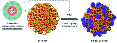
The degassed MOF (nano or micro)particles were mixed with the solution of metal chloride, and the stirred mixture was heated in a microwave (MW) oven for a few minutes (Fig. 3; it is worth noting that the loading of the MW reactor tube was done under inert gas conditions while the used ionic liquids had a low water content. The precautions were rather taken for the comparability of the results). The MW-heating conditions were chosen according to the typical temperatures at which the stabilized MNP colloids form without the MOF support, while additional limited stepwise optimization of the temperature and time was also performed in selected cases (see below).In this work, only the use of PdCl2 is reported in detail. The use of other precursors was less successful (for example, Pd(PPh3)4 instead of PdCl2 yielded well-deposited, but strongly agglomerated Pd-NPs with 1–5 nm sizes, ESI 6.5†). Other platinum group metals were also tested, with successful deposition in several cases. The sizes were dependent on the type of precursor, demonstrating the generality of the approach (one of the most successful examples was Rh-on-ZIF-8-NP starting from Rh6CO16 with nanoparticles of 1–3 nm size, ESI 6.6†).
Screening of Pd-on-ZIF-8-NP preparation regarding different ionic liquids
The results of the screening (Fig. 4) might be interpreted as manifestations of the next tendencies: (a) anions of low nucleophilicity are preferred; (b) the use of imidazolium based ILs might be beneficial; (c) the length of the aliphatic chain has rather a secondary importance. It is interesting to note that in the majority of the unsuccessful attempts the problem was in the deterioration of the ZIF-8 quality, manifested as a change of the particle morphology (particularly illustrative is the case of [BMPy]BF4 with otherwise very well-formed Pd-NPs). For all the subsequent experiments presented in that work, 1-butyl-3-methylimidazolium-bis(trifluoromethylsulfonyl)imide, [BMIm]NTf2, was used. However, the chosen IL is not unique regarding the possibility to perform the synthesis of the MNP-on-MOF materials. The potential drawback of using ILs with small counter anions is that the complete removal of the IL from MOF pores by washing might be complicated (ZIFs impregnated with ILs are known74,75).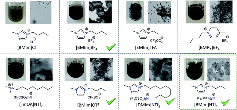 | ||
| Fig. 4 Screening of the Pd-on-ZIF-8-NP formation depending on the used ionic liquid (T = 180–230 °C). | ||
Nanoparticulated Pd-on-MOFNP composites
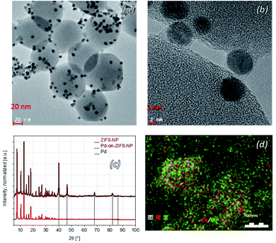
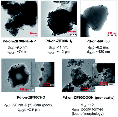
The synthesis of the “benchmark” material for this paper, the Pd-on-ZIF-8-NP, was performed at 230 °C in [BMIm]NTf2 under “standard conditions”, which were used for the synthesis of most other materials of this type featured in this contribution. The Pd-on-ZIF-8-NP arguably has the highest quality, with excellent preservation of the support's crystallinity and morphology, and uniform size of the crystalline Pd-NP nanoparticles (Fig. 5).Other materials, synthesized at 180 or 230 °C (according to screening-based optimization of conditions; see Table S5†), have generally somewhat or significantly lower quality (Fig. 6). It is reasonable to conjecture that the presence of polar groups (particularly H-bond donors) on the imidazolate ligands constituting the MOF support makes the latter less resistant to dissociative dissolution in the IL at the temperature of synthesis. The Pd-on-ZIF-90-COOH has the lowest quality: the MOF-support deteriorates under the conditions of the synthesis.
The large collection of the obtained TEM images (see ESI 6† for a detailed visual report) indicates that the nanoparticles are formed nearly exclusively on the surface of the particles. On none of the images are there any random variations of grayscale intensity between neighboring Pd particles, which would evidently be observed if the Pd-NPs had formed inside the MOF particles. Indeed, the micrograph is a projection and if the location-depth of the Pd-particle relatively to the surface is random, so should vary the grayscale intensity (the Pd-NPs behind a layer of MOF show correspondingly less contrast). Instead, there are zones with comparable contrast, corresponding to deposition on the faces of the MOF-nanoparticles. The effect is particularly clear when the facet of the particle, which is typically a well-formed nano- or microcrystal, is parallel to the viewing/imaging direction. The very high contrast of the respective areas, particularly for microparticles with large facets (e.g.Fig. 6, the case of Pd-on-ZIF-90-NH2 microcrystals), clearly demonstrates a highly dominant, practically exclusive, concentration of the particles on the surface, corresponding to the ‘-on-’ deposition.
The high resolution TEM images indicate the presence of a contact area between the particles and the support, and in some rare cases the particles even feature a thin continuous ‘halo’ around them. The high deposition temperature (230 °C) under MW-heating might cause a minor ‘baking-in’ of the particles onto the surface (at ∼280 °C, ZIF-8 starts to amorphize to form a glass;76 in the presence of 1-ethyl-3-methylimidazolium bis(trifluoromethanesulfonyl)imide the ‘melting’ takes place at 381 °C (ref. 77)).
Fe3O4/Pd-on-MOFNP and Pd/Fe3O4-on-MOFNP ferromagnetic composites
The feasibility of sequential multi-component deposition from ILs on the surface of the ZIF-NPs was tested by using an Fe2(CO)9 precursor, targeting Fe3O4 for the possibility of magnetic separation.Fe2(CO)9 is much less polar than PdCl2 and hence has potentially more affinity for the inner part of the MOF pores compared to the highly polar IL medium. On the other hand, Fe2(CO)9 is a relatively bulky molecule (smallest vdW diameter ∼8 Å), which should keep the molecule outside of the pores.
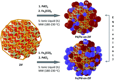
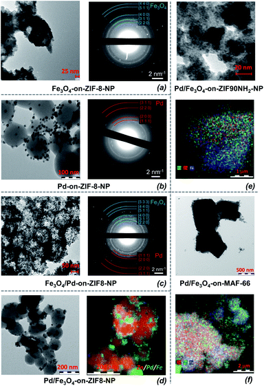
Two-step depositions, targeting Fe3O4/Pd-on-MOFNP and Pd/Fe3O4-on-MOFNP, were performed to compare the resultant materials both morphologically and regarding their catalytic properties (Fig. 7; the metal species are listed in the order of deposition). Both approaches were successfully realized (Fig. 8).
According to the selected area electron diffraction (SAED), the deposited iron is represented practically only by Fe3O4 (magnetite) for all the tested MOF substrates (ESI 6†). Therefore the Fe(0) in the carbonyl is oxidized by the media during the deposition, which is consistent with the elevated temperatures and potential acidity of the ILs (note that samples for the primary TEMs were sampled accurately under inert conditions, i.e. oxidation by air after synthesis is improbable). The size/shape of the Fe3O4 particles is not possible to characterize precisely due to low contrast, but the size of the diffuse “blots” is comparable to the size of the Pd-NPs (i.e. 5–13 nm vs. 6–12 nm across all samples, Table S5;† in some cases, the Fe3O4 aggregates form large blobs, with sizes difficult to determine). Despite the nondescript shape, they are crystallized enough to feature a clear diffraction pattern (Fig. 8).
Morphologically, there are no clear differences between the order of deposition of Fe3O4 and Pd, and the sizes of the Pd particles are roughly the same (i.e. the presence of Fe3O4 does not have a particularly strong influence on the deposition). The two TEM micrographs in Fig. 8 feature local areas with highly different local concentrations of the surface deposited particles for Fe3O4/Pd- and Pd/Fe3O4-on-ZIF-8 materials (such local concentration variations are quite typical for all the samples due to local concentration differences in the MW reactor). However, the character of the deposition is similar: there is a slight tendency towards aggregation, while the deposited material tends to concentrate around spots (which could be viewed as “anchors” of deposition, possibly at local defects, initially having elevated surface energy).
Despite the minor tendency of aggregation, the deposition is quite uniform regarding the distributions of small domains of agglomerated particles (larger differences exist for different samplings, rather due to incomplete homogenization during the deposition). Three types of proof regarding the local uniformity of distribution were selectively collected: TEM elemental imaging (down to a few nm scales), SAED (∼1 μm selected area size), and SEM elemental imaging (1+ μm); the “benchmark” materials based on ZIF-8 were analyzed using all three methods. There is a tendency of forming larger aggregates for larger microparticles, clearly visible in Fig. 8. All the methods confirm local clumping, with the size of the ‘clump’ containing the same element (Fe or Pd) being smaller than and commensurate with the size of a single MOF particle. The largest Fe3O4-containing aggregates of micrometric size (1 μm), which were rather ‘isles’ within areas of more even elemental distribution, were found in Pd/Fe3O4-on-MAF-66 with multi-micrometer sized MOF-support particles. The nanoparticulated MOF supports generally featured commensurate nanometer-sized aggregates. There is also a mild correlation in the concentration distribution of Pd and Fe3O4 which tend to localize in close proximity. However, there is no clear deposition-synergy except the expected non-specific “anchoring” by growing nanostructures with increased surface energy, serving as sites of probable seeding.
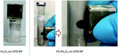
All the obtained Pd/Fe3O4- and Fe3O4-on-ZIF-NP composite particles were found to be indeed ferromagnetic due to the magnetite component (Fig. 9).
An additional note on the purity and uniformity of the MNP-on-ZIF-NP materials
The as-synthesized Pd-on-ZIF-NP materials dominantly consist of composite nanoparticles according to TEM-based methods, particularly elemental-imaging. Large metal particles were typical for non-successful synthetic attempts during the screening. Importantly the distribution of the Pd-NPs on the surface of the supports for the successful experiments is quite uniform. On the other hand, the reaction medium nearly always contains a certain amount of non-deposited Pd-NPs indicated by the deep black color of the solution even after centrifugation (this observation suggests that the deposition proceeds at elevated temperatures). Unlike the MOF nanoparticles, the smaller MNPs form stable colloids, which precipitate much slower under centrifugation, and hence low accelerations during the centrifugation were used. The separated precipitate was washed multiple times with acetonitrile to ensure minimal residual content of the individual non-coagulated Pd-NPs (mixtures of acetonitrile with ILs up to some concentration of the former do not cause immediate coagulation of the Pd-NPs. It is possible that washing with acetonitrile causes some additional precipitation of the particles on the MOF supports. In any case, the washing procedure is, though, one of the potentially poorly scalable operations regarding the purity and uniformity of the product).The problem of the possible impurities in the form of large aggregated Fe3O4 particles is less important for this work due to the aim at Pd-based catalysis. There were no clear indications of frequent large aggregates of pure Fe3O4 by TEM-imaging, supporting the tight “spatial association” of Fe and Pd species, with much better contrast of the conventional TEM images for the latter (seemingly also due to the more crystalline nature of the particles).
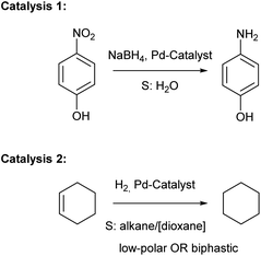
Catalysis 1: reduction of 4-nitrophenol to 4-aminophenol by NaBH4 in water
It is known that Pd/MOF composites59,78–80 are typically good catalysts in the reduction of the nitro-group by NaBH4 (Fig. 10). Accordingly, this type of catalysis was a natural choice for comparing the Pd-on-ZIF composites regarding their catalytic activity depending on functionalization. The reduction was performed in an aqueous solution and the catalyst was added last to a freshly prepared mixture of reactants (the reaction was found to be undetectably slow under the used conditions without the addition of a catalyst). The concentration of the 4-nitrophenol was determined by UV-vis-spectroscopy and the correctness of the determination was checked by HPLC in selected “benchmark” cases, particularly with the Pd-on-ZIF-8-NP composite (the check was deemed important because the spectrophotometric determination detected reliably only the 4-nitrophenol. However, the check of the 4-aminophenol concentration also allows elimination of the possibility of introducing errors via incorrect accounting of intermediary reactants. See ESI 7.1† for further details).Selected data on catalysis by Pd-on-ZIF-8-NP materials are summarized in Fig. 11. It is important to note the preservation of the particle morphology and crystallinity of the composite under the reaction conditions (there is a clear deterioration of the crystallinity of the Pd-NPs, but this is an expected outcome for catalytic species, which are subject to structural transformations that might both increase or decrease the catalytic activity with time). The other composites demonstrated moderately or significantly less preservation of crystallinity, particularly regarding the MOF-support (ESI 7.1†).
The kinetic curves, c(t), for most of the tested materials are shown in Fig. 12 (the curves are given on the individual and not common scale to better show their shape). As the NaBH4 is used in very large excess, the reaction kinetics is assumed to be pseudo-first order, ln(c0/c) = −kt, regarding the concentration of 4-nitrophenol. It is clearly visible that some of the curves could be nearly perfectly fit with an exponential function (particularly in the case of Pd/C), while in some other cases the fit is less good, to some extent for all ZIF-8 based materials, but particularly for the special case of Pd-on-ZIF-8-NP, where a very steep fall in concentration is followed by another section with a much slower decrease. The latter case is conspicuously different: it might indicate a change in the activity of the catalyst (it is worth noting that the Pd-on-ZIF-8-NP has demonstrated the highest morphological and structural stability, except the noted decrease of crystallinity of the Pd-NPs after the catalysis based on the PXRD).
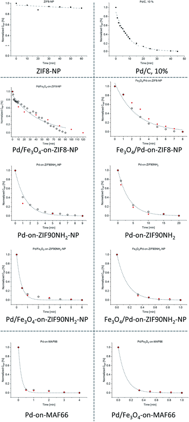 | ||
| Fig. 12 c(t), concentration(time), curves for the tested catalysts in the reduction of 4-nitrophenol by NaBH4 (black points correspond to UV-vis-based data and the red ones to selected HPLC checks). Note that the graphs have different scales (the Fe3O4-on-MOF materials have very small activity; see ESI 7.1†). | ||
The turnover frequency, TOF = nproduct/(ncatalyst × time), which could be expressed in differential form for TOF at time τ as {−(dc/dt)|t=τ × V}/{(mcat × xPd)/(MPd)}, was calculated according to the assumed pseudo-first order kinetics as TON0 = k × c0 × V × MPd/mcat × xPd, i.e. TON at the start of the reaction (see Tables 1, S6, and S7 and ESI 7.1† for a detailed description). The UV-vis based TON0 was cross-checked by HPLC based TON0,l.a values calculated as linear approximation, {[(c0 − c1)/t1] × V × MPd}/{mcat × xPd}, using the first measured point c1(t1). Such approximation is generally less precise compared to the results based on fitting, but in the case of poor fitting, it is deemed preferable. A very strong discrepancy between the TON0 and the cross-checked TON0,l.a. was found only for Pd-on-ZIF-8-NP and the latter value is regarded as more reasonable (selected TON0,l.a. values are given after TON0 values in parentheses for the cases with poor fitting in Table 1; the full list of TON0,l.a.vs. TON0 values is tabulated in Table S6, ESI†).
| Catalyst | x Pd, AAS, % wt | <d> Pd particles, nm | x Fe, AAS, % wt | <d> Fe3O4 particles, nm | <d> MOF-particles, nm | S surf, m2 g−1 | k, s−1 | TOF0, s−1 | TOF0,S, s−1 m−2 |
|---|---|---|---|---|---|---|---|---|---|
| a x is the AAS-based weight content of the respective element (for Pd/C the averaged content is given); <d> is the average size of the particles; Ssurf is the surface area; k is the fitted pseudo-first order reaction rate constant, found from the ln(c/c0)–t regression of the UV-vis spectroscopy-based data; TON0 is the turnover frequency at the start, calculated using the k value; TOF0,S is TON0/S1/2,Pd, where S1/2,Pd is the calculated half surface area of the Pd-particles, i.e. TOF0,S is the Pd-NP surface-specific TON; “n.d.” – the value was not determined with a reasonable precision, e.g. due to poor TEM-contrast; “—” – not applicable. b Poor fit by the pseudo-first order kinetic in the marked cases (ZIF-8 based materials). The alternative TOF in parentheses is estimated as a linear approximation using the first measurement point (HPLC based) and in the given cases it should rather be used instead of the primary value derived from the fitted k reaction rate constant. c The poor-quality samples (Pd-on-ZIF-90-CHO and particularly Pd-on-ZIF-90-COOH) were not investigated in-depth, though minimal catalytic testing was still performed. | |||||||||
| Pd-on-ZIF8-NP | 15.0 | 6 | — | — | 85 | 1646 | 0.00104 | 0.033 (0.473)b | 1.73 (24.8) |
| Pd-on-ZIF90NH2 | 4.6 | 11 | — | — | 1200 | 362 | 0.00368 | 0.38 | 122 |
| Pd-on-ZIF90NH2-NP | 12.3 | 12 | — | — | 88 | 0.00763 | 0.28 | 35.2 | |
| Pd-on-MAF66 | 8.8 | 8 | — | — | 426 | 0.01989 | 1.07 | 130 | |
| Pd-on-ZIF90CHOc | 11.9 | ∼20 | ∼2900 | 0.00150 | 0.06 | — | |||
| Pd-on-ZIF90COOHc | 14.6 | 12 | Poorly defined | 0.00156 | 0.05 | — | |||
| Fe3O4-on-ZIF8-NP | — | — | 11.9 | 5 | 83 | 568 | Low | — | |
| Fe3O4-on-ZIF90NH2 | — | — | 21.5 | 13 | 2500 | Low | — | ||
| Fe3O4-on-ZIF90NH2-NP | — | — | 16.7 | 11 | 81 | Low | — | ||
| Pd/Fe3O4-on-ZIF8-NP | 14.7 | 11 | 9.4 | n.d. | 117 | 0.00051 | 0.014 (0.016)b | 1.21 (1.38) | |
| Pd/Fe3O4-on-ZIF90NH2 | 9.5 | 6 | 10.6 | n.d. | 2400 | 0.07476 | 3.72 | 312 | |
| Pd/Fe3O4-on-ZIF90NH2-NP | 5.1 | 10 | 18.7 | n.d. | 70 | 0.01332 | 1.24 | 322 | |
| Pd/Fe3O4-on-MAF66 | 8.8 | 8 | 11.1 | n.d. | 420 | 0.10243 | 4.10 (1.88)b | 370 (170) | |
| Fe3O4/Pd-on-ZIF8-NP | 5.2 | n.d. | 5.1 | 4.7 | 0.01010 | 0.92 | n.d. | ||
| Fe3O4/Pd-on-ZIF90NH2-NP | 16.7 | n.d. | 20.4 | n.d. | — | 0.09564 | 2.73 | n.d. | |
| Pd/C, 10% | 10.0 | — | — | 900 | 0.00186 | 0.088 | — | ||
The analysis of Table 1 shows that generally all the Pd-containing composites have significantly higher catalytic activity by 1–2 orders of magnitude compared with Pd/C (10%wt, as supplied by Aldrich) except Pd-on-ZIF-8-NP, which has comparable activity (the precision is low due to the problems with ambiguous fitting in this case), and Pd/Fe3O4-on-ZIF-8-NP, which has slightly lower activity (the particles preserved their ferromagnetic properties after recovery). It could be speculated that the Fe3O4, deposited second, shields the Pd particles and this is the reason why the observed activity of Fe3O4/Pd-on-ZIF-8-NP is much higher (by almost two orders of magnitude). However, this explanation remains not quite satisfactory in some cases (e.g. Pd/Fe3O4-on-MAF66).
The highest TOF0 was observed for Pd/Fe3O4-on-MAF-66, where the support is microparticulated. In this case, the presence of Fe3O4 does not preclude the catalysis compared to Pd-on-MAF-66 (unfortunately, catalytic testing, which is essentially selective, was not performed with Fe3O4/Pd-on-MAF-66, which might have had even higher activity). The analysis of the data suggests an increase of activity for the amino-functionalized MOF supports (ZIF-90-NH2 and MAF-66), while the Fe3O4 acts as a mild promotor, increasing the activity further (it is important to stress that the ZIF-substrates, as well as the Fe3O4-on-ZIF composites, did not show significant catalytic activity).
It is important to note that the catalytic performance of the microparticulated supports seemingly does not decrease due to the larger particle sizes of the support. Comparable Pd-loading is reached due to higher density deposition: while the Pd-NPs in Pd-on-ZIF-8 are located quite sparsely, the surface concentration of NPs on the microparticulated supports is high (see Fig. 6 and ESI 7.1†). Still, the composites based on the amino-functionalized ZIF support demonstrate a clear advantage over Pd-on-ZIF-8-NP. This is particularly clear if the surface-specific TOF is analyzed (Table 1). While the observed Pd-NP sizes tend to be slightly larger on amino-functionalized supports, the surface of the exposed catalytic sites is accordingly smaller. The surface specific TOF in the case of composites based on amino-functionalized supports tends to be two orders of magnitude higher compared to ZIF-8 based ones. Such high efficiency of both nano- and microparticulated amino-functionalized composites is rather indirect proof that only surface deposition takes place (the considerable size of 4-nitrophenol/4-aminophenol compared to the pore-entrances in the ZIF-8 support means considerable diffusion limitations).
It is interesting to note in this regard the reported Pd@ZIF-8 nanoparticulated composites.59 These materials showed the highest catalytic activity in the reduction of p-nitrophenol when the share of the on-surface particles was deemed the largest, confirming the diffusion limitations imposed by the ZIF-8 host.
Catalysis 2: cyclohexene hydrogenation in apolar and biphasic media
Palladium on carbon (Pd/C) is a standard catalyst for hydrogenation of alkenes (Fig. 10) and hence a natural benchmark for the assessment of the expected catalytic activity of the Pd-on-ZIF composites in comparison (Table 2). The selected regime of the reaction was dictated by the available means: the amount of cyclohexene was chosen to be very large compared to the amount of catalyst and constituted typically the major part of the reaction medium (octane and decane were used as internal standards for GC-based yield cross-checking; dioxane was also used as a higher polarity additive). It was done for working under a near-constant concentration of the substrate and more reliable reaction progress monitoring via H2 consumption.| Sample name | Pd, % wt | Fe, % wt | Cat. wt, mg | C6H12 wt, g | Reaction mixture compositiona (vol. ratio) | Temp, °C | Time, h | Conversion to C6H14b, % | <TOF>c, s−1 |
|---|---|---|---|---|---|---|---|---|---|
| a C6H12: cyclohexene, C6H14: cyclohexane, Oct: octane, Dec: decane, Diox: dioxane. b GC based conversion of cyclohexene to cyclohexane within the given time (in a few cases H2-based yield is used; see the ESI). For long reaction times, not listed in the table, nearly quantitative yields were reached with Pd/C. c Average TOF, calculated for the whole time-span (underestimation of the rate of the faster reactions). | |||||||||
| Pd-on-ZIF8-NP | 19.7 | 0.0 | 2.00 | 1.62 | C6H12 100 | 80 | 21 | 0.0 | 0.000 |
| Pd-on-ZIF8-NP | 19.7 | 0.0 | 2.15 | 1.18 | C6H12![[thin space (1/6-em)]](https://www.rsc.org/images/entities/char_2009.gif) : :![[thin space (1/6-em)]](https://www.rsc.org/images/entities/char_2009.gif) Diox 95 Diox 95![[thin space (1/6-em)]](https://www.rsc.org/images/entities/char_2009.gif) : :![[thin space (1/6-em)]](https://www.rsc.org/images/entities/char_2009.gif) 5 5 |
80 | 2 | 0.2 | 0.001 |
| Pd/Fe3O4-on-ZIF8-NP | 14.7 | 9.4 | 2.18 | 1.18 | C6H12![[thin space (1/6-em)]](https://www.rsc.org/images/entities/char_2009.gif) : :![[thin space (1/6-em)]](https://www.rsc.org/images/entities/char_2009.gif) Diox 95 Diox 95![[thin space (1/6-em)]](https://www.rsc.org/images/entities/char_2009.gif) : :![[thin space (1/6-em)]](https://www.rsc.org/images/entities/char_2009.gif) 5 5 |
80 | 2 | 0.2 | 0.002 |
| Pd/Fe3O4-on-ZIF90NH2-NP | 5.1 | 18.7 | 2.07 | 1.18 | C6H12![[thin space (1/6-em)]](https://www.rsc.org/images/entities/char_2009.gif) : :![[thin space (1/6-em)]](https://www.rsc.org/images/entities/char_2009.gif) Diox 95 Diox 95![[thin space (1/6-em)]](https://www.rsc.org/images/entities/char_2009.gif) : :![[thin space (1/6-em)]](https://www.rsc.org/images/entities/char_2009.gif) 5 5 |
80 | 2 | 0.6 | 0.012 |
| Fe3O4/Pd-on-ZIF8-NP | 5.2 | 5.1 | 2.01 | 1.16 | C6H12![[thin space (1/6-em)]](https://www.rsc.org/images/entities/char_2009.gif) : :![[thin space (1/6-em)]](https://www.rsc.org/images/entities/char_2009.gif) Diox 95 Diox 95![[thin space (1/6-em)]](https://www.rsc.org/images/entities/char_2009.gif) : :![[thin space (1/6-em)]](https://www.rsc.org/images/entities/char_2009.gif) 5 5 |
80 | 2 | 0.3 | 0.005 |
| Pd-on-ZIF8-NP | 19.7 | 0.0 | 2.11 | 1.18 | C6H12![[thin space (1/6-em)]](https://www.rsc.org/images/entities/char_2009.gif) : :![[thin space (1/6-em)]](https://www.rsc.org/images/entities/char_2009.gif) Diox 95 Diox 95![[thin space (1/6-em)]](https://www.rsc.org/images/entities/char_2009.gif) : :![[thin space (1/6-em)]](https://www.rsc.org/images/entities/char_2009.gif) 5 5 |
80 | 2 | 0.4 | 0.002 |
| Pd-on-ZIF8-NP | 19.7 | 0.0 | 2.01 | 0.32 | C6H12![[thin space (1/6-em)]](https://www.rsc.org/images/entities/char_2009.gif) : :![[thin space (1/6-em)]](https://www.rsc.org/images/entities/char_2009.gif) Dec Dec![[thin space (1/6-em)]](https://www.rsc.org/images/entities/char_2009.gif) : :![[thin space (1/6-em)]](https://www.rsc.org/images/entities/char_2009.gif) H2O H2O![[thin space (1/6-em)]](https://www.rsc.org/images/entities/char_2009.gif) : :![[thin space (1/6-em)]](https://www.rsc.org/images/entities/char_2009.gif) Trit: 20 Trit: 20![[thin space (1/6-em)]](https://www.rsc.org/images/entities/char_2009.gif) : :![[thin space (1/6-em)]](https://www.rsc.org/images/entities/char_2009.gif) 5 5![[thin space (1/6-em)]](https://www.rsc.org/images/entities/char_2009.gif) : :![[thin space (1/6-em)]](https://www.rsc.org/images/entities/char_2009.gif) 75 75![[thin space (1/6-em)]](https://www.rsc.org/images/entities/char_2009.gif) : :![[thin space (1/6-em)]](https://www.rsc.org/images/entities/char_2009.gif) 1 1 |
80 | 2 | 1.7 | 0.002 |
| Pd/Fe3O4-on-ZIF8-NP | 19.6 | 0.0 | 2.03 | 0.32 | C6H12![[thin space (1/6-em)]](https://www.rsc.org/images/entities/char_2009.gif) : :![[thin space (1/6-em)]](https://www.rsc.org/images/entities/char_2009.gif) Dec Dec![[thin space (1/6-em)]](https://www.rsc.org/images/entities/char_2009.gif) : :![[thin space (1/6-em)]](https://www.rsc.org/images/entities/char_2009.gif) H2O H2O![[thin space (1/6-em)]](https://www.rsc.org/images/entities/char_2009.gif) : :![[thin space (1/6-em)]](https://www.rsc.org/images/entities/char_2009.gif) Trit: 20 Trit: 20![[thin space (1/6-em)]](https://www.rsc.org/images/entities/char_2009.gif) : :![[thin space (1/6-em)]](https://www.rsc.org/images/entities/char_2009.gif) 5 5![[thin space (1/6-em)]](https://www.rsc.org/images/entities/char_2009.gif) : :![[thin space (1/6-em)]](https://www.rsc.org/images/entities/char_2009.gif) 75 75![[thin space (1/6-em)]](https://www.rsc.org/images/entities/char_2009.gif) : :![[thin space (1/6-em)]](https://www.rsc.org/images/entities/char_2009.gif) 1 1 |
80 | 2 | 4.1 | 0.006 |
| Pd-on-ZIF90NH2-NP | 4.9 | 0.0 | 2.03 | 0.31 | C6H12![[thin space (1/6-em)]](https://www.rsc.org/images/entities/char_2009.gif) : :![[thin space (1/6-em)]](https://www.rsc.org/images/entities/char_2009.gif) Dec Dec![[thin space (1/6-em)]](https://www.rsc.org/images/entities/char_2009.gif) : :![[thin space (1/6-em)]](https://www.rsc.org/images/entities/char_2009.gif) H2O H2O![[thin space (1/6-em)]](https://www.rsc.org/images/entities/char_2009.gif) : :![[thin space (1/6-em)]](https://www.rsc.org/images/entities/char_2009.gif) Trit: 20 Trit: 20![[thin space (1/6-em)]](https://www.rsc.org/images/entities/char_2009.gif) : :![[thin space (1/6-em)]](https://www.rsc.org/images/entities/char_2009.gif) 5 5![[thin space (1/6-em)]](https://www.rsc.org/images/entities/char_2009.gif) : :![[thin space (1/6-em)]](https://www.rsc.org/images/entities/char_2009.gif) 75 75![[thin space (1/6-em)]](https://www.rsc.org/images/entities/char_2009.gif) : :![[thin space (1/6-em)]](https://www.rsc.org/images/entities/char_2009.gif) 1 1 |
80 | 2 | 31.6 | 0.173 |
| ZIF8-NP | 0.0 | 0.0 | 2.08 | 1.62 | C6H12 100 | 80 | 5 | 0.0 | 0.000 |
| Pd/C, 10%wt | 10.0 | 0.0 | 2.00 | 3.85 | C6H12![[thin space (1/6-em)]](https://www.rsc.org/images/entities/char_2009.gif) : :![[thin space (1/6-em)]](https://www.rsc.org/images/entities/char_2009.gif) Oct 95 Oct 95![[thin space (1/6-em)]](https://www.rsc.org/images/entities/char_2009.gif) : :![[thin space (1/6-em)]](https://www.rsc.org/images/entities/char_2009.gif) 5 5 |
24 | 2 | 8.7 | 0.296 |
| Pd/C, 10%wt | 10.0 | 0.0 | 2.00 | 3.85 | C6H12![[thin space (1/6-em)]](https://www.rsc.org/images/entities/char_2009.gif) : :![[thin space (1/6-em)]](https://www.rsc.org/images/entities/char_2009.gif) Oct 95 Oct 95![[thin space (1/6-em)]](https://www.rsc.org/images/entities/char_2009.gif) : :![[thin space (1/6-em)]](https://www.rsc.org/images/entities/char_2009.gif) 5 5 |
50 | 2 | 26.2 | 0.887 |
| Pd/C, 10%wt | 10.0 | 0.0 | 2.00 | 3.85 | C6H12![[thin space (1/6-em)]](https://www.rsc.org/images/entities/char_2009.gif) : :![[thin space (1/6-em)]](https://www.rsc.org/images/entities/char_2009.gif) Oct 95 Oct 95![[thin space (1/6-em)]](https://www.rsc.org/images/entities/char_2009.gif) : :![[thin space (1/6-em)]](https://www.rsc.org/images/entities/char_2009.gif) 5 5 |
80 | 2 | 52.0 | 1.760 |
| Pd/C, 10%wt | 10.0 | 0.0 | 2.17 | 0.08 | C6H12![[thin space (1/6-em)]](https://www.rsc.org/images/entities/char_2009.gif) : :![[thin space (1/6-em)]](https://www.rsc.org/images/entities/char_2009.gif) Diox 10 Diox 10![[thin space (1/6-em)]](https://www.rsc.org/images/entities/char_2009.gif) : :![[thin space (1/6-em)]](https://www.rsc.org/images/entities/char_2009.gif) 90 90 |
80 | 24 | 38.2 | 0.002 |
| Pd/C, 10%wt | 10.0 | 0.0 | 2.12 | 1.17 | C6H12![[thin space (1/6-em)]](https://www.rsc.org/images/entities/char_2009.gif) : :![[thin space (1/6-em)]](https://www.rsc.org/images/entities/char_2009.gif) Diox 95 Diox 95![[thin space (1/6-em)]](https://www.rsc.org/images/entities/char_2009.gif) : :![[thin space (1/6-em)]](https://www.rsc.org/images/entities/char_2009.gif) 5 5 |
80 | 2 | 14.0 | 0.136 |
| Pd/C, 10%wt | 10.0 | 0.0 | 2.08 | 0.32 | C6H12![[thin space (1/6-em)]](https://www.rsc.org/images/entities/char_2009.gif) : :![[thin space (1/6-em)]](https://www.rsc.org/images/entities/char_2009.gif) Dec Dec![[thin space (1/6-em)]](https://www.rsc.org/images/entities/char_2009.gif) : :![[thin space (1/6-em)]](https://www.rsc.org/images/entities/char_2009.gif) H2O H2O![[thin space (1/6-em)]](https://www.rsc.org/images/entities/char_2009.gif) : :![[thin space (1/6-em)]](https://www.rsc.org/images/entities/char_2009.gif) Trit: 20 Trit: 20![[thin space (1/6-em)]](https://www.rsc.org/images/entities/char_2009.gif) : :![[thin space (1/6-em)]](https://www.rsc.org/images/entities/char_2009.gif) 5 5![[thin space (1/6-em)]](https://www.rsc.org/images/entities/char_2009.gif) : :![[thin space (1/6-em)]](https://www.rsc.org/images/entities/char_2009.gif) 75 75![[thin space (1/6-em)]](https://www.rsc.org/images/entities/char_2009.gif) : :![[thin space (1/6-em)]](https://www.rsc.org/images/entities/char_2009.gif) 1 1 |
80 | 2 | 42.1 | 0.113 |
Additionally, it was done due to the limited size of a catalytic material batch, which should have been divided for multiple experiments. In order to reach high conversion rates in reasonably short times, a relatively high pressure of hydrogen (8 bar) was used at elevated temperature (∼80 °C). Importantly, a pressure of 2 bar at room temperature was principally sufficient for detectable reaction seeds in most of the tested cases, but the reaction rates were too slow for the majority of the less active samples. Therefore, the more aggressive conditions were used for the sake of better comparability.
A large series of experiments, with only some selected results shown in Table 2, allow the conclusion that the activity of the Pd-on-ZIF composites in the alkene hydrogenation reaction is much lower compared to that of Pd/C (10% weight, as supplied by Aldrich), unlike in the reaction of 4-nitrophenol reduction. The experiments and the analysis of the results were optimized towards finding exceptions, and hence a simplified assessment was done by estimating the <TOF> using the whole time range. Such an approach underestimates somewhat the speed of the reaction, resulting in higher yield due to a faster decrease of concentration. However, while very high initial concentrations of cyclohexene (typically >90%) were used, the relative concentration change under a low-to-medium conversion regime was relatively low. Accordingly, the method is valid for qualitative comparisons.
ZIF-8 alone was not an active catalyst, and the presence of Fe-species did not change the activity of Pd-species appreciably (the extent of preservation of Fe3O4 under intensive hydrogenation was not investigated, though quantitative preservation of ferromagnetism after catalysis was confirmed for selected tested cases).
The low activity of Pd-on-ZIFs was observed in nearly all cases. The most evident hypothesis regarding the low catalytic activity of the Pd-on-ZIF materials is the inhibiting role of IL, both as a protective layer in apolar media and via poisoning due to reduction of the sulfur-containing anion. It is worth noting that some other Pd@ZIF-8 materials were reported to be active in hydrogenation of cyclohexene62,81 even if the size-exclusion effect was also observed at least partially,60 while in Au@ZIF-8 (ref. 82) and Pt@ZIF-8 (ref. 83) with thick ZIF-8 shells, which crucially influence diffusion,84 the reaction was negligibly small at least at room temperature. The use of Pd-on-ZIFs in more polar dioxane-based reaction mixtures with higher capabilities regarding the dissolution of ILs proved to be inefficient. Notably, the dioxane-rich mixtures caused a drop in TOF for the Pd/C catalyst.
The catalysis under biphasic conditions (low polar organics, water, Triton X-100 as a surfactant) demonstrated slightly improved rates with one notable exception of Pd-on-ZIF90NH2-NP. The latter was comparable with Pd/C under the same conditions, which still meant an order of magnitude lower rates compared to those of Pd/C in monophasic low polar media. Repeated experiments with the same material showed a high spread of results regarding the former material, which might indirectly support its possible instability. Better purification of the particles from ILs or using sulfur-free ILs might provide better results. The used conditions are rather preliminary, without the focus on using the MOF as a H2-depot, as solvents like octane, decane, or water could easily enter the pores. However, they suggest that the amino-functionalized supports tend to impart the highest activity.
Conclusions
Ionic liquids (ILs) are introduced as a medium for metal nanoparticle (MNP) deposition on nano- or microparticulated ZIF supports, yielding well-formed MNP-on-ZIF(-NP)s. Extensive TEM studies on six composites using different supports confirm that the deposition from the ILs yields nearly exclusively on-surface deposition (the large size of the IL-solvated Pd-species, exceeding the size of the support pores, together with their high polarity and affinity for the PdCl2 precursor offers a straightforward rationalization; cf. with predominant encapsulation when Pd(acac)2 is used in DMF44). The use of ILs opens up broader prospects for MNP-on-MOFNP based materials, as ILs are one of the best media for electrostatic stabilization of nanoparticles, being much less acidic and often more substrate-compatible compared to water. The deposition of Pd-NPs from ILs was presented as a demonstration of a method. According to our preliminary results the deposition method has general applicability, suitable also for deposition of smaller nanoparticles (with sizes of 1–5 nm) starting from metal carbonyls of other noble and transition metals. ILs as a medium for synthesis of MNPs offer synthetic generality, giving access to small nanoparticles of both noble and non-noble metals such as Rh, Pd, Pt, Ir, Ru, Au, Ag, Cu, Fe, Co, Ni, and others.It was shown that morphologically similar ferromagnetic Pd/Fe3O4-on-ZIFs and Fe3O4/Pd-on-ZIFs could be obtained via sequential one-pot deposition. The roughly similar size of Pd nanoparticles in all composites (∼10 nm) and its relatively weak dependence on the presence of the Fe3O4 or the type of support (with somewhat larger particles in the case of amino-functionalized supports) shows that the main initial stabilization comes from the IL-medium. Hence, the approach demonstrates the feasibility of one-pot multi-species deposition of NPs on ZIF-supports. The morphologically and structurally most stable and well-formed composite observed is the Pd-on-ZIF8-NP (regarded in this work as a benchmark), which might be explained by the higher stability of a MOF based on a less polar/hydrophilic ligand in hot ionic liquid during the synthesis and in polar media during the catalytic experiments.
In the reduction of 4-nitrophenol by NaBH4 in water, which was used as a benchmark catalytic reaction, the Pd-on-MOFs demonstrated high performance, matching (ZIF-8 support) or exceeding significantly (ZIF-90-NH2 and MAF-66 amino-functionalized supports) the efficiency of Pd/C (10%). The composites based on microparticulated amino-functionalized ZIF supports, featuring a dense surface layer of Pd-NPs according to TEM analysis, did demonstrate similar performance compared to the sparsely covered nanoparticulated composites, which indirectly reinforces the exclusively on-surface deposition of the Pd-NPs. The poorly formed Pd-on-ZIF composites with R = CHO and COOH functionalization demonstrated significantly lower activity compared to Pd/C, which might be due to their generally lower stability in ILs.
In contrast, the hydrogenation of cyclohexene in apolar media was very unspectacular compared to that of Pd/C, most probably due to the poisoning of the catalyst due to the presence of residual IL. The use of biphasic octane/water media demonstrated a tendency towards improved rates; however, the results are not quite conclusive.
Well-formed MNP-on-ZIFs, with the possibility of introducing multiple nanoparticulated components in one step, are interesting synergistic H2-depots and precursors for derived composites, including electrode materials (nano-particulated precursors could be mixed components in arbitrary proportions for property fine-tuning of the resulting compacted electrode). The future targets revolve around optimization of the synergism of the functional MNPs and porosity of the support in processes, which involve gases, particularly hydrogen.
Conflicts of interest
There are no conflicts to declare.Acknowledgements
The authors gratefully acknowledge the contributions of Dr Karsten Klauke and Dr Marvin Siebels for acquisition of selected TEM images; Dr Laura Schmolke for the help with the Karl Fischer titrations and ion chromatography; Dr Alexa Schmitz for collecting the TG-data, Mrs Annette Ricken for performing the AAS determinations, and Mrs Birgit Tommes for acquiring the IR spectra. We thank the CeMSA@HHU (Center for Molecular and Structural Analytics @ Heinrich Heine University) for recording the mass-spectrometric and the NMR-spectroscopic data. This research was supported by a joint National Natural Science Foundation of China–Deutsche Forschungsgemeinschaft (NSFC-DFG) project (DFG JA466/39-1).Notes and references
- J. C. Lacroix, Q. van Nguyen, Y. Ai, Q. van Nguyen, P. Martin and P. C. Lacaze, Polym. Int., 2019, 68, 607–619 CrossRef CAS.
- C. L. Bentley, M. Kang and P. R. Unwin, J. Am. Chem. Soc., 2019, 141, 2179–2193 CrossRef CAS PubMed.
- R. W. Murray, Chem. Rev., 2008, 108, 2688–2720 CrossRef CAS PubMed.
- R. Hao, R. Xing, Z. Xu, Y. Hou, S. Gao and S. Sun, Adv. Mater., 2010, 22, 2729–2742 CrossRef CAS PubMed.
- D. Astruc, Chem. Rev., 2020, 120, 461–463 CrossRef CAS PubMed.
- H. S. Mader, P. Kele, S. M. Saleh and O. S. Wolfbeis, Curr. Opin. Chem. Biol., 2010, 14, 582–596 CrossRef CAS PubMed.
- S. Kundu and A. Patra, Chem. Rev., 2017, 117, 712–757 CrossRef CAS PubMed.
- C. J. Tang, Y. N. Liu, C. Xu, J. X. Zhu, X. J. Wei, L. Zhou, L. He, W. Yang and L. Q. Mai, Adv. Funct. Mater., 2018, 28, 1704561 CrossRef.
- L. Qin, G. Zeng, C. Lai, D. Huang, P. Xu, C. Zhang, M. Cheng, X. Liu, S. Liu, B. Li and H. Yi, Coord. Chem. Rev., 2018, 359, 1–31 CrossRef CAS.
- J. N. Anker, W. P. Hall, O. Lyandres, N. C. Shah, J. Zhao and R. P. Van Duyne, Nat. Mater., 2008, 7, 442–453 CrossRef CAS PubMed.
- H. Ju, Applied Materials Today, 2018, 10, 51–71 CrossRef.
- J. Ma, X. Wang, J. Feng, C. Huang and Z. Fan, Small, 2021, 17, e2004287 CrossRef PubMed.
- W. H. De Jong and P. J. Borm, Int. J. Nanomed., 2008, 3, 133–149 CrossRef CAS PubMed.
- S. Wegner and C. Janiak, Top. Curr. Chem., 2017, 375, 65 CrossRef PubMed.
- C. Janiak, Z. Naturforsch., B: J. Chem. Sci., 2013, 68, 1059–1089 CrossRef CAS.
- J. D. Scholten, B. C. Leal and J. Dupont, ACS Catal., 2011, 2, 184–200 CrossRef.
- G. Chacón and J. Dupont, ChemCatChem, 2018, 11, 333–341 CrossRef.
- O. Bartlewicz, I. Dąbek, A. Szymańska and H. Maciejewski, Catalysts, 2020, 10, 1227–1247 CrossRef CAS.
- P. Claus and F. Schwab, RSC Catal. Ser., 2014, 2014, 391–409 Search PubMed.
- N. J. Costa and L. M. Rossi, Nanoscale, 2012, 4, 5826–5834 RSC.
- R. J. White, R. Luque, V. L. Budarin, J. H. Clark and D. J. Macquarrie, Chem. Soc. Rev., 2009, 38, 481–494 RSC.
- J. Liu, L. Chen, H. Cui, J. Zhang, L. Zhang and C. Y. Su, Chem. Soc. Rev., 2014, 43, 6011–6061 RSC.
- S. Yuan, L. Feng, K. Wang, J. Pang, M. Bosch, C. Lollar, Y. Sun, J. Qin, X. Yang, P. Zhang, Q. Wang, L. Zou, Y. Zhang, L. Zhang, Y. Fang, J. Li and H. C. Zhou, Adv. Mater., 2018, 30, e1704303 CrossRef PubMed.
- S. Kaskel, The Chemistry of Metal-Organic Frameworks, Wiley-VCH, 2016 Search PubMed.
- H. Furukawa, K. E. Cordova, M. O'Keeffe and O. M. Yaghi, Science, 2013, 341, 1230444 CrossRef PubMed.
- Q. L. Zhu and Q. Xu, Chem. Soc. Rev., 2014, 43, 5468–5512 RSC.
- A. U. Czaja, N. Trukhan and U. Muller, Chem. Soc. Rev., 2009, 38, 1284–1293 RSC.
- P. Silva, S. M. F. Vilela, J. P. C. Tomé and F. A. Almeida Paz, Chem. Soc. Rev., 2015, 44, 6774–6803 RSC.
- J. R. Li, R. J. Kuppler and H. C. Zhou, Chem. Soc. Rev., 2009, 38, 1477–1504 RSC.
- Y. B. Huang, J. Liang, X. S. Wang and R. Cao, Chem. Soc. Rev., 2017, 46, 126–157 RSC.
- S. Chen, W. H. Li, W. Jiang, J. Yang, J. Zhu, L. Wang, H. Ou, Z. Zhuang, M. Chen, X. Sun, D. Wang and Y. Li, Angew. Chem., Int. Ed. Engl., 2022, 61, e202114450 CAS.
- W. Zhang, C. Huang, J. Zhu, Q. Zhou, R. Yu, Y. Wang, P. An, J. Zhang, M. Qiu, L. Zhou, L. Mai, Z. Yi and Y. Yu, Angew. Chem., Int. Ed. Engl., 2022, 61, e202112116 CAS.
- W. P. Lustig, S. Mukherjee, N. D. Rudd, A. V. Desai, J. Li and S. K. Ghosh, Chem. Soc. Rev., 2017, 46, 3242–3285 RSC.
- L. Wang, Y. Han, X. Feng, J. Zhou, P. Qi and B. Wang, Coord. Chem. Rev., 2016, 307, 361–381 CrossRef CAS.
- M. Giménez-Marqués, T. Hidalgo, C. Serre and P. Horcajada, Coord. Chem. Rev., 2016, 307, 342–360 CrossRef.
- S. Dang, Q.-L. Zhu and Q. Xu, Nat. Rev. Mater., 2017, 3, 17075 CrossRef.
- T. Wen, G. Quan, B. Niu, Y. Zhou, Y. Zhao, C. Lu, X. Pan and C. Wu, Small, 2021, 17, e2005064 CrossRef PubMed.
- M. Meilikhov, K. Yusenko, D. Esken, S. Turner, G. Van Tendeloo and R. A. Fischer, Eur. J. Inorg. Chem., 2010, 3701–3714 CrossRef CAS.
- G. Lu, S. Li, Z. Guo, O. K. Farha, B. G. Hauser, X. Qi, Y. Wang, X. Wang, S. Han, X. Liu, J. S. DuChene, H. Zhang, Q. Zhang, X. Chen, J. Ma, S. C. Loo, W. D. Wei, Y. Yang, J. T. Hupp and F. Huo, Nat. Chem., 2012, 4, 310–316 CrossRef CAS PubMed.
- Y. Wang, L. Chen, C. C. Hou, Y. S. Wei and Q. Xu, Org. Biomol. Chem., 2020, 18, 8508–8525 RSC.
- J. J. Low, A. I. Benin, P. Jakubczak, J. F. Abrahamian, S. A. Faheem and R. R. Willis, J. Am. Chem. Soc., 2009, 131, 15834–15842 CrossRef CAS PubMed.
- X. Cai, Z. Xie, D. Li, M. Kassymova, S.-Q. Zang and H.-L. Jiang, Coord. Chem. Rev., 2020, 417, 213366 CrossRef CAS.
- J. Cravillon, R. Nayuk, S. Springer, A. Feldhoff, K. Huber and M. Wiebcke, Chem. Mater., 2011, 23, 2130–2141 CrossRef CAS.
- H. Kobayashi, Y. Mitsuka and H. Kitagawa, Inorg. Chem., 2016, 55, 7301–7310 CrossRef CAS PubMed.
- M. Zhang, Y. Gao, C. Li and C. Liang, Chin. J. Catal., 2015, 36, 588–594 CrossRef CAS.
- H. L. Jiang, B. Liu, T. Akita, M. Haruta, H. Sakurai and Q. Xu, J. Am. Chem. Soc., 2009, 131, 11302–11303 CrossRef CAS PubMed.
- P. Z. Li, K. Aranishi and Q. Xu, Chem. Commun., 2012, 48, 3173–3175 RSC.
- H. Dai, B. Xia, L. Wen, C. Du, J. Su, W. Luo and G. Cheng, Appl. Catal., B, 2015, 165, 57–62 CrossRef CAS.
- L. Shi, X. Zhu, T. Liu, H. Zhao and M. Lan, Sens. Actuators, B, 2016, 227, 583–590 CrossRef CAS.
- Y. Zhao, M. Liu, B. Fan, Y. Chen, W. Lv, N. Lu and R. Li, Catal. Commun., 2014, 57, 119–123 CrossRef CAS.
- M. Yurderi, A. Bulut, M. Zahmakiran, M. Gülcan and S. Özkar, Appl. Catal., B, 2014, 160–161, 534–541 CrossRef CAS.
- F. Liu, X. Liu, J. Ren, G. Xia and R. Song, Nanosci. Nanotechnol. Lett., 2016, 8, 770–773 CrossRef.
- G. Zheng, S. de Marchi, V. Lopez-Puente, K. Sentosun, L. Polavarapu, I. Perez-Juste, E. H. Hill, S. Bals, L. M. Liz-Marzan, I. Pastoriza-Santos and J. Perez-Juste, Small, 2016, 12, 3935–3943 CrossRef CAS PubMed.
- P. Wang, J. Zhao, X. Li, Y. Yang, Q. Yang and C. Li, Chem. Commun., 2013, 49, 3330–3332 RSC.
- C. J. Stephenson, J. T. Hupp and O. K. Farha, Inorg. Chem. Front., 2015, 2, 448–452 RSC.
- C. Li, M. Zhang, X. Di, D. Yin, W. Li and C. Liang, Chin. J. Catal., 2016, 37, 1555–1561 CrossRef CAS.
- S. Ding, Q. Yan, H. Jiang, Z. Zhong, R. Chen and W. Xing, Chem. Eng. J., 2016, 296, 146–153 CrossRef CAS.
- M. Zhang, Y. Yang, C. Li, Q. Liu, C. T. Williams and C. Liang, Catal. Sci. Technol., 2014, 4, 329–332 RSC.
- H. Jiang, Q. Yan, R. Chen and W. Xing, Microporous Mesoporous Mater., 2016, 225, 33–40 CrossRef CAS.
- Q. Yang, Q. Xu, S. H. Yu and H. L. Jiang, Angew. Chem., Int. Ed. Engl., 2016, 55, 3685–3689 CrossRef CAS PubMed.
- C. Wang, H. Zhang, C. Feng, S. Gao, N. Shang and Z. Wang, Catal. Commun., 2015, 72, 29–32 CrossRef CAS.
- X. Wang, M. Li, C. Cao, C. Liu, J. Liu, Y. Zhu, S. Zhang and W. Song, ChemCatChem, 2016, 8, 3224–3228 CrossRef CAS.
- C. Rösler, D. Esken, C. Wiktor, H. Kobayashi, T. Yamamoto, S. Matsumura, H. Kitagawa and R. A. Fischer, Eur. J. Inorg. Chem., 2014, 2014, 5514–5521 CrossRef.
- M. Sadakiyo, M. Kon-no, K. Sato, K. Nagaoka, H. Kasai, K. Kato and M. Yamauchi, Dalton Trans., 2014, 43, 11295–11298 RSC.
- H. Yin, J. Choi and A. C. K. Yip, Catal. Today, 2016, 265, 203–209 CrossRef CAS.
- P. Wang, J. Liu, C. Liu, B. Zheng, X. Zou, M. Jia and G. Zhu, Chemistry, 2016, 22, 16613–16620 CrossRef CAS PubMed.
- A. Ayala, C. Carbonell, I. Imaz and D. Maspoch, Chem. Commun., 2016, 52, 5096–5099 RSC.
- H. L. Jiang, T. Akita, T. Ishida, M. Haruta and Q. Xu, J. Am. Chem. Soc., 2011, 133, 1304–1306 CrossRef CAS PubMed.
- C. Hou, G. F. Zhao, Y. J. Ji, Z. Q. Niu, D. S. Wang and Y. D. Li, Nano Res., 2014, 7, 1364–1369 CrossRef CAS.
- J. A. Villajos, G. Orcajo, G. Calleja, J. A. Botas and C. Martos, Int. J. Hydrogen Energy, 2016, 41, 19439–19446 CrossRef CAS.
- H. Zhou, J. Zhang, D. Ji, A. Yuan and X. Shen, Microporous Mesoporous Mater., 2016, 229, 68–75 CrossRef CAS.
- X. Jia, S. Wang and Y. Fan, J. Catal., 2015, 327, 54–57 CrossRef CAS.
- T. Thanh Dang, A. Chen and A. Majeed Seayad, RSC Adv., 2014, 4, 30019–30027 RSC.
- K. Fujie, T. Yamada, R. Ikeda and H. Kitagawa, Angew. Chem., Int. Ed. Engl., 2014, 53, 11302–11305 CrossRef CAS PubMed.
- K. Fujie, R. Ikeda, K. Otsubo, T. Yamada and H. Kitagawa, Chem. Mater., 2015, 27, 7355–7361 CrossRef CAS.
- L. Longley, S. M. Collins, S. Li, G. J. Smales, I. Erucar, A. Qiao, J. Hou, C. M. Doherty, A. W. Thornton, A. J. Hill, X. Yu, N. J. Terrill, A. J. Smith, S. M. Cohen, P. A. Midgley, D. A. Keen, S. G. Telfer and T. D. Bennett, Chem. Sci., 2019, 10, 3592–3601 RSC.
- V. Nozari, C. Calahoo, J. M. Tuffnell, D. A. Keen, T. D. Bennett and L. Wondraczek, Nat. Commun., 2021, 12, 5703 CrossRef CAS PubMed.
- Q. Yang, F. Yao, Y. Zhong, F. Chen, X. Shu, J. Sun, L. He, B. Wu, K. Hou, D. Wang and X. Li, Part. Part. Syst. Charact., 2019, 36, 1800557 CrossRef.
- B. Xu, X. Li, Z. Chen, T. Zhang and C. Li, Microporous Mesoporous Mater., 2018, 255, 1–6 CrossRef CAS.
- H. Jiang, Q. Yan, Y. Du and R. Chen, React. Kinet., Mech. Catal., 2015, 117, 307–317 CrossRef.
- T. Zhang, B. Li, X. Zhang, J. Qiu, W. Han and K. L. Yeung, Microporous Mesoporous Mater., 2014, 197, 324–330 CrossRef CAS.
- C. J. Stephenson, C. L. Whitford, P. C. Stair, O. K. Farha and J. T. Hupp, ChemCatChem, 2016, 8, 855–860 CrossRef CAS.
- C. J. Stephenson, J. T. Hupp and O. K. Farha, Inorg. Chem., 2016, 55, 1361–1363 CrossRef CAS PubMed.
- A. Yazdi, F. Mercoçi, N. G. Bastús, I. Imaz, V. Puntes and D. Maspoch, Catal. Sci. Technol., 2016, 6, 8388–8391 RSC.
Footnote |
| † Electronic supplementary information (ESI) available: Synthesis of the MOF supports and the composite materials, their characterization by PXRD, TEM/SAED and SEM, including elemental imaging, AAS, BET-based surface areas, and methodology of the catalytic experiments. See DOI: 10.1039/d2ta00883a |
| This journal is © The Royal Society of Chemistry 2022 |

