
 Open Access Article
 This Open Access Article is licensed under a
 Creative Commons Attribution 3.0 Unported Licence
Design of high-performance antimony/MXene hybrid electrodes for sodium-ion batteries†
Stefanie
Arnold
 ab,
Antonio
Gentile
cd,
Yunjie
Li
ab,
Qingsong
Wang
ae,
Stefano
Marchionna
d,
Riccardo
Ruffo
*cf and
Volker
Presser
*abg
ab,
Antonio
Gentile
cd,
Yunjie
Li
ab,
Qingsong
Wang
ae,
Stefano
Marchionna
d,
Riccardo
Ruffo
*cf and
Volker
Presser
*abg
aINM – Leibniz Institute for New Materials, Campus D2.2, 66123 Saarbrücken, Germany. E-mail: volker.presser@leibniz-inm.de
bDepartment of Materials Science and Engineering, Saarland University, Campus D2.2, 66123 Saarbrücken, Germany
cDipartimento di Scienza dei Materiali, Università degli Studi di Milano Bicocca, Via Cozzi 55, 20125 Milano, Italy. E-mail: riccardo.ruffo@unimib.it
dRicerca sul Sistema Energetico-RSE S.p.A., Via R. Rubattino 54, 20134 Milano, Italy
eInstitute of Nanotechnology, Karlsruhe Institute of Technology, Hermann-von-Helmholtz-Platz 1, Eggenstein-Leopoldshafen, 76344, Germany
fNational Reference Center for Electrochemical Energy Storage (GISEL) – Consorzio Interuniversitario Nazionale per la Scienza e Tecnologia dei Materiali (INSTM), 50121 Firenze, Italy
gSaarene – Saarland Center for Energy Materials and Sustainability, Campus D4.2, 66123 Saarbrücken, Germany
First published on 24th March 2022
Abstract
Due to their versatile properties and excellent electrical conductivity, MXenes have become attractive materials for alkali metal-ion batteries. However, as the capacity is limited to lower values due to the intercalation mechanism, these materials can hardly keep up in the ever-fast-growing community of battery research. Antimony has a promisingly high theoretical sodiation capacity characterized by an alloying reaction. The main drawback of this type of battery material is related to the high volume changes during cycling, often leading to electrode cracking and pulverization, resulting in poor electrochemical performance. A synergistic effect of combing antimony and MXene can be expected to obtain an optimized electrochemical system to overcome capacity fading of antimony while taking advantage of MXene charge storage ability. In this work, variation of the synthesis parameters and material design strategy have been dedicated to achieving the optimized antimony/MXene hybrid electrodes for high-performance sodium-ion batteries. The optimized performance does not align with the highest amount of antimony, the smallest nanoparticles, or the largest interlayer distance of MXene but with the most homogeneous distribution of antimony and MXene while both components remain electrochemically addressable. As a result, the electrode with 40 mass% MXene, not previously expanded, etched with 5 mass% HF and 60% antimony synthesized on the surfaces of MXene emerged as the best electrode. We obtained a high reversible capacity of 450 mA h g−1 at 0.1 A g−1 with a capacity retention of around 96% after 100 cycles with this hybrid material. Besides the successful cycling stability, this material also exhibits high rate capability with a capacity of 365 mA h g−1 at 4 A g−1. In situ XRD measurements and post mortem analysis were used to investigate the reaction mechanism.
1 Introduction
Their large energy density, high power density, and output voltage make lithium-ion batteries (LIBs) an essential technology for electrochemical energy storage systems.1 As a result of the increasing demand for batteries, scarcity of fossil resources of lithium, and the resulting rise in price, energy storage technologies beyond lithium are of high interest.2,3 Sodium is one of the most abundant elements in the earth's crust. Thus, sodium-ion batteries (NIBs) offer cost-effective and sustainable energy storage compared to their LIB counterparts.4 In recent years, extensive research efforts have been dedicated to NIB cathodes and anodes with high energy density, high power density, stable cycling performance, and good rate capability.2,5,6 A particular challenge is the development of anodes that combine high capacity and long lifetime/high durability. Several studies focus on carbon-based materials as an alternative for graphite anodes, as they are used successfully in LIBs.7,8 Hard carbon, the most widespread carbonaceous material in NIBs, can only achieve a capacity of up to 300 mA h g−1 because of pseudocapacitive Na+-ion surface adsorption.9–13 Other intercalation materials like Li4Ti5O12,14–16 TiO2,17 and Na2Ti3O7 (ref. 18) are well known for their high structural stability, which enables high reversibility during sodiation and de-sodiation. Still, a major drawback is that the Na+-ion intercalation enabled capacity is limited due to the restricted number of storage sites.19 This makes choosing high-capacity materials capable of forming sodium-rich intermetallic compounds through an alloying reaction extremely attractive, as demonstrated by extensive research on this topic published in the literature.6,20–23 Sodium can form alloys with group 14 and 15 elements, such as Ge, Sn, Pb, P, and Sb. Intermetallic compounds such as NaGe,24 Na15Sn4,25 Na15Pb4,26 Na3P,27 and Na3Sb28 are obtained which can realize a high sodium storage capacity. A major problem of alloying-based materials is the large volume change during sodiation and de-sodiation. This process causes possible aggregation, continuous reformation of the solid–electrolyte interphase (SEI), depletion of the electrolyte, and loss of the conductivity as well as slower kinetics which often leads to capacity fading.20,21,29 This constitutes a major drawback since side reactions are constantly occurring during cycling, resulting in low Coulombic efficiency (CE). In addition, the inhomogeneous composition and thickness of the continuously restructured SEI can partly block charge transfer and cause typical rapid capacity fading.30–34 With a high theoretical capacity of 660 mA h g−1, a high specific capacity and the ease of availability of the material, antimony (Sb) represents a very common and promising anode material candidate for high energy NIBs.1,35 Still, during the alloying reaction of antimony with sodium resulting in Na3Sb compounds, this material suffers from high volume expansion (∼300%) and contraction and slow reaction kinetics resulting in capacity fading and poor electrochemical performance.20,35–37 Therefore, it is crucial to buffer the volume change sufficiently to mitigate pulverization and cracking of the electrode, while increasing the conductivity and improving the electrochemical performance.21,38Besides the specific adaptations and variations of the binder and electrolytes, current work mainly presents two different approaches to counteract these problems. A promising path is to develop suitable carbon matrices, which act as a conductive additive and buffer the volume change occurring during sodiation and de-sodiation and provide additional diffusion pathways.21,36,39–44 For example, Pfeifer et al. investigated the impact of carbon properties on antimony/carbon composite electrodes for NIBs by simple mechanical mixing only by considering the physical, chemical, and structural features of the carbon phase.45 An alternative way is to develop suitable nanostructures/nanocomposites, which should improve the kinetics.21 MXenes, a novel class of two-dimensional, inorganic layered transition metal carbides, nitrides, and carbonitrides, were discovered in 2011.46 Among them, several MXenes are promising intercalation-type electrodes, for example, for LIBs and NIBs because of their distinctive physical and chemical properties.47,48 Comparing 2D materials, MXenes stand out with their combined properties such as good electronic conductivity, hydrophilicity, and flexibility.48,49 Furthermore, due to their low activation barrier for ion movement, they also represent an optimal candidate for NIBs.50,51 Kajiyama et al. showed that the intercalation and deintercalation of the sodium-ions between Ti3C2Tz sheets occur without any substantial structural change with a reversible capacity of around 100 mA h g−1 over 100 cycles at 0.02 A g−1.52 Gentile et al. showed different preparation routes of MXenes resulting in different structures, compositions, properties, and morphologies and investigated their influence on the application of NIBs.53 The optimized Ti3C2Tz shows a capacity of 110 mA h g−1 at a specific current of 0.03 A g−1.
Although MXene is an interesting electrode material, its intrinsic performance is commonly limited to the intercalation mechanism.54 Accordingly, the resulting de-sodiation capacity is also limited to lower values than alloying or conversion type materials.55 An attractive way to overcome this limitation is to combine MXene with other nanoparticles, either by forming nanocomposites or hybrids. This has been very successfully explored for different electrochemical applications, such as sensors,56 photocatalysis,57 and energy storage.58 The list of nanomaterials used to enhance different types of MXenes is long and includes MnO2,59 MoS2,60 NiCo2S4,61 NbS2,62 and TiO2,63 along with polymers (such as polyvinyl alcohol; ref. 64). Combining MXene and non-MXene materials extends to MXenes and alloying materials. Confining and synergizing materials like antimony with a high specific capacity and conductive MXene is promising to yield improved electrochemical performance and cycling stability. Combining the most common and best-explored MXene Ti3C2Tz with antimony nanoparticles is expected to enhance the structural stability resulting in a long cycling life since there is a minimal volume change of the 2D nanomaterial during alkali metal transport. This includes NIBs65 but also extends to other systems, such as potassium-ion batteries.66,67 In addition, MXene nanosheets show excellent mechanical stability, compensating for significant volume changes during charging and discharging in nanomaterials like alloying materials during cycling.68 This avoids or reduces agglomeration and the possible subsequent pulverization, which is also reflected in improved electrochemical behavior.
This work presents a guideline for designing an advanced hybrid antimony MXene compound for application in high-performance NIBs. We introduce two different routes for the hybrid material synthesis by variation of two different types of MXenes and compositions. In this way, different morphologies and compositions were obtained whose impact on the electrochemical performance in NIBs was studied. Finally, electrodes with an optimized synthesis protocol demonstrated stable and high-capacity electrochemical cycling stability and rate capability in NIBs.
2 Experimental
2.1 Materials synthesis
Two different Ti3C2Tz MXenes were obtained in this work, referred to as MX_HF5 and MX_HF30. The synthesis of MX_HF5, treated with a 5 mass% solution of hydrofluoric acid (HF) proceeds as described below. In a polytetrafluoroethylene beaker, 2 g of Ti3AlC2 powder was stirred in 50 mL of 5 mass% HF in water for 24 h at room temperature. The powder was added slowly to the reaction solution within 2 min since the reaction between HF and the MAX phase leads to a strong evolution of H2 in the solution. After 24 h, the solution was centrifuged for 15 min at 5000 rpm, and the subsequent precipitate was recovered from the supernatant, washed with MilliQ water, and centrifuged 5–6 times until the pH value of the solution was 6. The powder was finally dried under vacuum at 80 °C overnight.
For the synthesis of MX_HF30, treated with a 30 mass% hydrofluoric acid solution, the procedure is similar to the previous one, except for the treatment time. In a typical synthesis, 2 g of Ti3AlC2 powder was dispersed in 50 mL of 30 mass% HF in water under vigorous stirring at room temperature for 5 h. The hydrogen evolution is greater than the previous case, so the powder is added within 5 min. The washing and the drying procedure were the same as those of MX_HF5.
In synthesis route B, the synthesized 100 mg Ti3C2Tz (etched with 5 mass% HF or 30 mass% HF) was soaked in a solution of SbCl3 dissolved in 30 mL absolute ethanol for 12 h. To this suspension, a solution with an excess of NaBH4 in 40 mL technical ethanol was dropped at a speed of 20 mL h−1 to reduce the Sb3+-ions and form the elemental antimony particles.
2.2 Structural and chemical characterization
X-ray diffraction (XRD) measurements of the antimony hybrids were performed with three different systems. XRD-1: A D8 Advance diffractometer (Bruker AXS, Germany) with a copper X-ray source (Cu-Kα, λ = 1.5406 Å, 40 kV, 40 mA). The samples were examined in the range of 3.5° to 80° 2θ and with 0.033 s per step. XRD-2: A D8 Discover diffractometer (Bruker AXS, Germany) with a copper X-ray source (Cu-Kα, λ = 1.5406 Å, 40 kV, 40 mA), a Göbel mirror and a 1 mm point focus as optics. With a VANTEC-500 (Bruker AXS) two-dimensional X-ray detector positioned at 17° 2θ, 37° 2θ, 57° 2θ, and 97° 2θ with a measurement time of 1000 s per step, five frames were recorded. The third system (XRD-3) is outlined in Section 2.4.2. Unless noted, all presented XRD patterns are related to measurements that were carried out by using XRD-1.The sample morphology was characterized with a field emission scanning electron microscope using a Zeiss Gemini 500 instrument (Carl Zeiss) at an acceleration voltage of 1 kV. The samples were fixed on a steel sample holder by using copper adhesive tape and analyzed without the aid of an additional, conductive sputter coating.
Transmission electron microscopy and selected area electron diffraction investigations were carried out using a JEOL 2011 instrument operated at 200 kV. The sample was dispersed in ethanol through sonication for 5 min and drop-casted onto a copper grid with a lacy carbon film.
2.3 Electrode materials and preparation
Pure MXene working electrodes were obtained with a ratio of 90 mass% MXene, and 10 mass% carboxymethyl cellulose (CMC, degree of substitution = 0.7, molecular weight = 250![[thin space (1/6-em)]](https://www.rsc.org/images/entities/char_2009.gif) 000 g mol−1, Sigma Aldrich) dissolved in water and ethanol (1:1 mass ratio) following the subsequently described mixing steps. The Sb@ Ti3C2Tz/C electrodes were manufactured by mixing an active material of 80 mass% of the different synthesized antimony MXene hybrids (Sb@A_MX_HF5(6:4), Sb@A_MX_HF5(7:3), Sb@B_MX_HF5(6:4), Sb@B_MX_HF5(7:3), Sb@A_MX_ HF30(6:4), Sb@A_MX_HF30(7:3), Sb@B_MX_HF30(6:4), and Sb@B_MX_HF30(7:3)) with 10 mass% conductive carbon additive (C-NERGY SUPER C65 conductive carbon black, Imerys Graphite & Carbon) and 10 mass% CMC as the binder from a 3 mass% aqueous solution according to the mixing steps described below.
000 g mol−1, Sigma Aldrich) dissolved in water and ethanol (1:1 mass ratio) following the subsequently described mixing steps. The Sb@ Ti3C2Tz/C electrodes were manufactured by mixing an active material of 80 mass% of the different synthesized antimony MXene hybrids (Sb@A_MX_HF5(6:4), Sb@A_MX_HF5(7:3), Sb@B_MX_HF5(6:4), Sb@B_MX_HF5(7:3), Sb@A_MX_ HF30(6:4), Sb@A_MX_HF30(7:3), Sb@B_MX_HF30(6:4), and Sb@B_MX_HF30(7:3)) with 10 mass% conductive carbon additive (C-NERGY SUPER C65 conductive carbon black, Imerys Graphite & Carbon) and 10 mass% CMC as the binder from a 3 mass% aqueous solution according to the mixing steps described below.
First, the active material and carbon were mixed and carefully dry ground in a mortar. Afterward, the dry powder mixture was dry-mixed at 1000 rpm for 5 min in a SpeedMixer DAC 150 SP from Hauschild. Ethanol (99.0% purity, Merck) was added dropwise to the mixture until the slurry achieved suitable viscosity. This paste was again mixed at 1500 rpm for 5 min followed by 2500 rpm for 5 min. Finally, the CMC binder solution (3 mass% CMC in Milli-Q-water) was added, and the viscous electrode paste kept mixing at 800 rpm for 10 min. The suspension was stirred for 12 hours with a magnetic stirrer to obtain a homogeneous slurry. The subsequently obtained slurries were doctor-bladed on aluminum foil (thickness of 15 μm, Ranafoil, Toyo Aluminium), and used as a current collector, with a wet thickness of 200 μm. The electrode coatings were initially dried under ambient conditions overnight. Then, an extra vacuum drying step was conducted at +110 °C for 12 h to remove the remaining solvent. The packing density of the electrode was adjusted by dry-pressing within a rolling machine (HR01 hot rolling machine, MTI), and discs of 12 mm diameter (1.131 cm2) were punched from the electrode sheet using a press-punch (EL-CELL) and applied as the working electrode.
For comparison to the hybrid active material, simple mechanical mixing (MM) of the active antimony material, MXene, conductive carbon, and the binder solution was conducted in analogy to the procedure reported for the hybrid Sb@MXene. These samples were prepared to recreate the composition of the related hybrid materials and are referred to as Sb + MX_HF5(6:4)_MM and Sb + MX_HF5(7:3)_MM. The ensuing electrode thickness of the dried electrodes was typically 25–35 μm with a material loading of 3.8 ± 0.5 mg cm−2.
2.4 Cell preparation and electrochemical characterization
All used cell parts were dried overnight at +120 °C and introduced into an argon-filled glovebox (MBraun Labmaster 130, O2 < 0.1 ppm, H2O < 0.1 ppm). Initially, the punched working electrode with a diameter of 12 mm was placed in the cell, followed by a 13 mm diameter vacuum dried compressed glass-fiber separator (GF/D, Whatman). The counter electrode was punched into circular plates with a diameter of 10 mm and placed on the separator. Before using metallic sodium, the oxidized surface was polished to obtain a smooth surface to avoid non-uniformity and impurities. The counter electrodes were pressed to a uniform thickness of approximately 1 mm. A copper foil current collector was placed on the backside of each counter electrode. The sodium reference electrode was placed on a compressed glass-fiber separator (GF/D, Whatman) with a diameter of 2 mm in a cavity close to the working electrode/counter electrode stack and brought into contact with a titanium wire. The electrolyte was vacuum backfilled with a syringe into the cells.
The preparation and handling of the electrolyte solvent and salt were conducted in an argon-filled glovebox. A 1 M sodium perchlorate (NaClO4, >99% purity, Alfa Aesar) solution in a solvent mixture of ethylene carbonate (EC, ≥99% purity, Sigma Aldrich) and dimethyl carbonate (DMC, ≥99% purity, Sigma Aldrich) in a 1:1 mass ratio with the addition of 5 mass% fluoroethylene carbonate (FEC, 99% purity, Sigma Aldrich) was used as the electrolyte. FEC is commonly used as a NIB additive that improves the stability of the SEI, modifying the composition of the SEI layer and preventing the decomposition of EC and DMC.71–75 The sodium salt for the electrolyte was dried under vacuum at +80 °C for 48 h before use.
Galvanostatic cycling with potential limitation, cyclic voltammetry, and rate performance measurements were carried out using a VMP3 multi-channel potentiostat/galvanostat (Bio-Logic) equipped with the EC-Lab software. All electrochemical measurements were carried out in a climate chamber (Binder) at a constant temperature of +25 ± 1 °C. Cyclic voltammetry was carried out with a scan rate of 0.1 mV s−1 in a potential window of 0.1–2.0 V vs. Na+/Na. The galvanostatic charge/discharge cycles were performed in the voltage range of 0.1–2.0 V vs. Na+/Na. For all long cycling tests in this work, a specific current of 0.1 A g−1 was used. The cycling of the cells was stopped after 100 cycles in the de-sodiated state to conduct post mortem XRD and SEM analysis. Rate performance measurements were conducted at different currents to get more information about the half-cell rate capability and stability at higher currents. The applied specific currents were 0.1 A g−1, 0.2 A g−1, 0.5 A g−1, 1.0 A g−1, 2.0 A g−1, 4.0 A g−1, 8.0 A g−1, and (again) 0.1 A g−1. All obtained values for the capacity in Sb/MXene vs. sodium cells are related to the respective active mass (i.e., the total mass of the antimony–Ti3C2Tz hybrid).
3 Results and discussion
3.1 Material characterization
The main process of synthesizing the antimony hybrid material is illustrated in Fig. 1. Thereby antimony hybrids were prepared by two different routes. In route A, the synthesized MXenes (etched with 5 mass% or 30 mass% hydrofluoric acid (HF)) were first expanded with the use of tetramethylammonium hydroxide (TMAOH) as the intercalant. In route B, the not-expanded MXene (etched with 5 mass% or 30 mass% HF) was soaked in the reaction solution of SbCl3 in ethanol to possibly anchor the Sb3+ cations already on the surface and between the layers. In both cases, a co-precipitation method of synthesizing the antimony nanoparticle at the MXene is followed to obtain the antimony MXene hybrids. In this way, two hybrids with different compositions (Sb:Ti3C2Tz 70%:30% and 60%:40% by mass) were prepared for each type of MXene and each route, respectively.
 | ||
| Fig. 1 Schematic illustration of the different synthesis routes of the antimony/MXene hybrids. Route A represents a previous expansion of the MXene layers before synthesizing the antimony/MXene hybrids while route B depicts intercalation of SbCl3 in the MXene before subsequent antimony/MXene hybrid synthesis. | ||
All hybrids, the synthesized MXenes, and the expanded MXenes were characterized by X-ray diffraction (Fig. 2). The pure MXene phases (MX_HF5 and MX_HF30) each show well-defined diffraction peaks for the (002), (004), and (006) reflections which are indicative of the stacking sequence along the c-axis and the (110) distinct reflection, which characterizes the Ti–C order. The XRD pattern in Fig. 2A after expansion (A_MX_HF5) shows a strong (002) peak at 6.00° 2θ, compared to the initial value of (002)-Ti3C2Tz at 8.67° 2θ. The same observation can be made by looking at Fig. 2B where the (002) peak in pristine MXene (etched with 30 mass% HF) is found at 8.95° 2θ and undergoes a backshift to 5.89° 2θ after performing expansion/exfoliation (A_MX_HF30). This backshift of the (002) reflection is characterized by a significant increase in d-spacing along the c-axis, which corresponds to an increased value of 45% for the MXene etched with 5 mass% HF (MX_HF5) to the expanded MXene (A_MX_HF5) and a value of 51% for the MXene etched with 30 mass% HF (MX_HF30) to the expanded MXene (A_MX_HF30).
 | ||
| Fig. 2 X-ray diffractograms using Cu-Kα radiation for different compositions of the as-synthesized antimony MXene hybrid materials (A) with MXene etched with 5 mass% HF (B) with MXene etched with 30 mass% HF. | ||
The XRD patterns of all hybrids where the MXene was etched with 5 mass% HF as reported in Fig. 2A and ESI, Fig. S1† show the characteristic peaks of elemental antimony with the space group R![[3 with combining macron]](https://www.rsc.org/images/entities/char_0033_0304.gif) m (PDF: 00-035-0732). This indicates that the antimony particles were successfully synthesized. In the two hybrids where no prior expansion/exfoliation took place (Sb@B_MX_HF5(7:3) and Sb@B_MX_HF5(6:4)), the antimony reflections show a significantly higher intensity than the hybrids where MXenes were previously expanded using TMAOH (Sb@A_MX_HF5(7:3) and Sb@A_MX_HF5(6:4)). This may align with the facile distribution of antimony nanoparticles between the MXene layers when the interlayers were expanded by partial exfoliation beforehand. The shielding of Sb nanoparticles by the MXene layers and the lower dimensional level of the crystallographic coherence domains also decreases the corresponding signal detectable via X-ray diffraction. Comparing the MXene reflections, the reflections of the two compounds obtained by route B (Sb@B_MX_HF5(7:3) and Sb@B_MX_HF5(6:4)) show significantly less intensity than their counterparts obtained by the previous expansion of the MXene layers (Sb@A_MX_HF5(7:3) and Sb@A_MX_HF5(6:4)).
m (PDF: 00-035-0732). This indicates that the antimony particles were successfully synthesized. In the two hybrids where no prior expansion/exfoliation took place (Sb@B_MX_HF5(7:3) and Sb@B_MX_HF5(6:4)), the antimony reflections show a significantly higher intensity than the hybrids where MXenes were previously expanded using TMAOH (Sb@A_MX_HF5(7:3) and Sb@A_MX_HF5(6:4)). This may align with the facile distribution of antimony nanoparticles between the MXene layers when the interlayers were expanded by partial exfoliation beforehand. The shielding of Sb nanoparticles by the MXene layers and the lower dimensional level of the crystallographic coherence domains also decreases the corresponding signal detectable via X-ray diffraction. Comparing the MXene reflections, the reflections of the two compounds obtained by route B (Sb@B_MX_HF5(7:3) and Sb@B_MX_HF5(6:4)) show significantly less intensity than their counterparts obtained by the previous expansion of the MXene layers (Sb@A_MX_HF5(7:3) and Sb@A_MX_HF5(6:4)).
The low-intensity (002) reflections are shifted towards smaller scattering angles compared to the reflections of the bulk Ti3C2Tz. The samples Sb@B_MX_HF5(7:3) and Sb@B_MX_HF5(6:4) demonstrate that even without prior expansion of the MXene layers with TMAOH, there is a clear shift of bulk (002)-Ti3C2Tz from 8.67° 2θ to 6.83° 2θ and 6.72° 2θ, respectively. This is caused by the expansion of the MXene interlayer distance due to the Sb3+ intercalation. This can also be explained by the different reaction routes. Due to the previous expansion (route A), some antimony particles will enter between the layers of the MXene, and a large part of the surface of the MXene remains free, which can be well detected in the XRD pattern. In contrast, reaction route B yields antimony particles on the surface of the MXene. The latter forms a layer around the MXene particles, which makes the Sb reflections more pronounced in the pattern.
For the antimony hybrid material synthesized based on MXene etched with 30 mass% HF (Fig. 2B), the observations agree with those for 5 mass% HF MXene. Only the reflection pattern of the hybrid with 40% expanded MXene, and 60% antimony (Sb@A_MX_30(6:4)) is conspicuous in which it shows pronounced reflections for the antimony particles compared to the compounds synthesized in the same way. A different morphology can explain this phenomenon compared to synthesis route B, where larger antimony particles are produced. The larger antimony particles which cannot be intercalated into the interlayers are therefore present in the hybrid. Generally, no TiO2 reflections were detected, suggesting that the MXene layers are not oxidized or only limited MXene flakes are oxidized during the synthesis process but beyond the detection limit of XRD characterization.
The electron micrographs shown in Fig. 3 complement the findings gained from the X-ray diffractograms. While the bulk Ti3C2Tz (5 mass% HF) presents the morphology of relative compact layers, the resulting antimony hybrid with 60% antimony shows that the Ti3C2Tz particles are covered with partially agglomerated nanoparticles of antimony with a primary size of about 150–250 nm. A particle size distribution graph of the obtained antimony particles in different synthesis routes derived from SEM micrographs are provided in ESI, Fig. S2.† The remarkable difference in the two particle sizes and especially the agglomerated Sb nanoparticles of synthesis route B may be due to possible electrostatic adsorption of the Sb3+-ions on the MXene layers.65 Partially, the antimony particles are also located between the layers of the MXene. After the expansion of the bulk Ti3C2Tz using TMAOH, the MXene layers look expanded and much thinner, and the particles look much smaller (Fig. 3C). Following synthesis route A, antimony particles were also synthesized on the surface of the MXene layers. In this route, significantly smaller primary particle sizes of 20–50 nm are formed, creating agglomerates. In addition, due to the smaller particle size, antimony particles and the formed agglomerates can diffuse into the expanded MXene layers. Synthesis conditions can also explain these observations since in synthesis route A NaBH4 was first added to the MXene suspension; therefore, the sodium-ions can be electrostatically adsorbed on the surface of the MXene.76,77 Due to this, the remaining free areas on the surface are limited for Sb3+ adsorption, whereby these are diffused more efficiently between the layers. The differences in the particle size of the antimony particles can also be explained by the predominant concentration of antimony ions on the surface, which is significantly larger in route B, allowing seed crystals to form and fuse more easily into large particles and remain so after reduction. Under both conditions, we observe a well-developed homogeneity. Comparing the latter hybrids with Ti3C2Tz etched with 30 mass% HF, similar conclusions are drawn except that this bulk MXene has a much more open structure from the beginning, which does not affect the antimony synthesis. Additional scanning electron micrographs of the different compositions are provided in ESI, Fig. S3–S6.†
 | ||
| Fig. 3 Scanning electron micrograph of (A) as-synthesized Ti3C2Tz etched with 5 mass% HF, (B) Ti3C2Tz (5 mass% HF) hybrid with 60 mass% antimony, (C) TMAOH expanded Ti3C2Tz_HF5, (D) Ti3C2Tz_HF5 hybrid with 60 mass% antimony, (E) as-synthesized Ti3C2Tz etched with 30 mass% HF, (F) Ti3C2Tz (30 mass% HF) hybrid with 60 mass% antimony, (G) TMAOH expanded Ti3C2Tz_HF30 and (H) Ti3C2Tz_HF30 hybrid with 60 mass% antimony. | ||
Fig. 4 displays the results obtained by transmission electron microscopy, which verify the SEM findings. The synthesis route with the previous expansion of the MXene layers enables significantly smaller antimony particles in-between the expanded MXene. In contrast, in the synthesis route without prior expansion of the MXene layers, significantly larger particles are obtained, which adhere mainly agglomerates to the surface of the MXene particles. Specifically, antimony is mostly located between the MXene layers (Sb@A_MX_HF5(6:4)) which explains less pronounced reflections of elemental antimony in the X-ray diffractograms. The reflection planes of selected-area electron diffractograms (Fig. 4E and F) confirm the results obtained from XRD, with the clear evidence of elemental antimony with the space group Rm in Sb@A_MX_HF5(6:4) (Fig. 4E) and Sb@B_MX_HF5(6:4) (Fig. 4F).
 | ||
| Fig. 4 Transmission electron micrographs of (A and C) TMAOH expanded Ti3C2Tz (5 mass% HF) hybrid with 60 mass% antimony and (B and D) bulk Ti3C2Tz (5 mass% HF) hybrid with 60 mass% antimony. Selected-area electron diffraction of (E) TMAOH expanded Ti3C2Tz (5 mass% HF) hybrid with 60 mass% antimony, and (F) bulk Ti3C2Tz (5 mass% HF) hybrid with 60 mass% antimony. | ||
3.2 Electrochemical characterization
To characterize the electrochemical performance of the Sb@Ti3C2Tz hybrids as anodes for sodium-ion batteries, cyclic voltammetry profiles in the initial ten cycles were investigated at a scan rate of 0.1 mV s−1 between 0.1 V and 2.0 V vs. Na+/Na and can be found in detail in ESI, Fig. S7.†The third cycles of each of the eight antimony Ti3C2Tz hybrid materials are shown comparatively in Fig. 5. After SEI formation, the typical peaks for the alloying reaction of antimony with sodium occur mainly for all hybrids. Thus, the reduction peaks at around 0.7 V and 0.55 V (and 0.45 V) vs. Na+/Na characterize the multistep transformation of antimony into hexagonal Na3Sb. The complete reaction proceeds from elemental antimony to the formation of an amorphous NaxSb compound from which NaSb is finally reacting further with sodium to crystalline Na3Sb.35,78 The oxidation peak in the subsequent de-sodiation scan at a potential of around 0.8 V vs. Na+/Na characterizes the de-sodiation reaction of the NaxSb alloy back to amorphous elemental antimony. Looking more closely at the performance of the hybrids with the MXene etched with 5 mass% HF, it is noticeable that in the hybrids synthesized in route A, the intensities of the oxidation and the reduction peaks are significantly lower. In addition, the reduction and oxidation peaks are shifted to lower and higher potentials, respectively. This indicates that comparatively more antimony is electrochemically active and addressable in the hybrids in which the Sb3+-ions have been previously intercalated (route B). This is consistent with the observations from the material characterization. The shift of the peaks probably indicates that the charge transfer process is more difficult for the samples with previously expanded MXene layers and intercalated antimony nanoparticles.79
 | ||
| Fig. 5 Electrochemical characterization of the antimony MXene hybrids showing the 3rd cycles of the cyclic voltammograms at a scan rate of 0.1 mV s−1 in a potential range from 0.1 V to 2.0 V vs. Na+/Na: (A) hybrids based on MX_HF5% (Sb@A_MX_HF5(6:4) and Sb@A_MX_HF5(7:3), and Sb@B_MX_HF5(6:4) and Sb@B_MX_HF5(7:3)). (B) Hybrids based on MX_HF30% (Sb@A_MX_HF30(6:4) and Sb@A_MX_HF30(7:3), and Sb@B_MX_HF30(6:4) and Sb@B_MX_HF30(7:3)). | ||
Hybrids with MXene etched with 30 mass% HF still show the three reduction peaks and one oxidation peak. HF30 hybrids with 60% antimony show similar intensities of the peaks, whereas both HF30 hybrids with 70% antimony show significantly less of this signal. In contrast to Sb@B_MX_HF30(6:4), the oxidation peak of Sb@A_MX_HF30(6:4) is shifted towards a higher potential and has no shoulder. The oxidation peak of Sb@B_MX_HF30(7:3) has a very broad shoulder at a lower intensity of the main peak, and the peak at Sb@A_MX_HF30(7:3) is much broader and shifted towards smaller potential. The first reduction peak at 0.7 V vs. Na+/Na is overlapping in three of the hybrid materials, whereas in the hybrid with expanded MXene and 70% antimony, the peak is very weak or not pronounced at all. In general, the redox peaks obtained for the hybrid with MXene etched with 30 mass% HF are broadened, indicating poorer kinetics due to the poorly conductive path of the large particles. There are also broadened peaks for the samples with non-expanded MXene, attributed to larger particle sizes. The same can be said for the subsequent reduction peaks at 0.55 V and 0.45 V vs. Na+/Na. The cyclic voltammograms of pure Ti3C2Tz_HF5 and Ti3C2Tz_HF30 anodes show a more pseudo-rectangular shape without obvious sodiation and de-sodiation peaks (ESI, Fig. S7 and S8†).80
The obtained reduction and oxidation peaks from cyclic voltammetry agree with the galvanostatic discharge and charge profiles tested at different specific currents in a voltage range between 0.1 and 2.0 V vs. Na+/Na as shown in Fig. 6A and B. Sb@A_MX_HF5(6:4) and Sb@B_MX_HF5(6:4) show different plateaus corresponding to the redox reactions associated with sodium alloying/de-alloying. This multistage process is visible for all electrodes and results in the formation of three pronounced plateaus which are consistent for antimony with observations in previous studies.35,78 The initial sodiation curve of the Sb@B_MX_HF5(6:4) material (Fig. 6B) exhibits a long plateau at 0.5 V vs. Na+/Na, which can, besides the alloying products, be assigned to the formation of SEI films on the electrode.78 In contrast, the electrode with Sb@A_MX_HF5(6:4) (Fig. 6A) shows significantly more plateaus in the first cycle. This may indicate a different SEI formation process or the possibility of side reactions that may take place due to trace impurities from the expansion process using TMAOH. During the following cycles at higher specific currents, both compounds continuously show the plateaus reflecting the alloying reaction from crystalline antimony to amorphous NaxSb, then to cubic and hexagonal Na3Sb mixtures and finally resulting in hexagonal Na3Sb.35
 | ||
| Fig. 6 Electrochemical performance of the antimony MXene hybrid electrodes. (A and B) Galvanostatic charge and discharge profiles at different applied specific currents of 0.1–8 A g−1 between 0.1 V and 2.0 V vs. Na+/Na for (A) Sb@A_MX_HF5(6:4), and (B) Sb@B_MX_HF5(6:4). (C and D) Rate performance using galvanostatic charge/discharge cycling with the corresponding Coulombic efficiency values at different values for the specific current for (C) hybrids based on MX_HF5% (Sb@A_MX_HF5(6:4) and Sb@A_MX_HF5(7:3), and Sb@B_MX_HF5(6:4) and Sb@B_MX_HF5(7:3)), and (D) hybrids based on MX_HF30% (Sb@A_MX_HF30(6:4) and Sb@A_MX_HF30(7:3), and Sb@B_MX_HF30(6:4) and Sb@B_MX_HF30(7:3)). (E and F) Galvanostatic charge/discharge cycling stability at 0.1 A g−1 for (E) hybrids based on MX_HF5% (Sb@A_MX_HF5(6:4) and Sb@A_MX_HF5(7:3), and Sb@B_MX_HF5(6:4) and Sb@B_MX_HF5(7:3)), and (F) hybrids based on MX_HF5% (Sb@A_MX_HF30(6:4) and Sb@A_MX_HF30(7:3), and Sb@B_MX_HF30(6:4), and Sb@B_MX_HF30(7:3)). | ||
The most significant difference between the two hybrids obtained with different synthesis routes is the potential drift of the galvanostatic curves. While the profiles of Sb@A_MX_HF5(6:4) have similar shapes during cycling, the charge plateaus of Sb@B_MX_HF5(6:4) shift clearly in the lower capacity direction while the discharge curve plateaus remain almost constant. This may indicate increasing overvoltage in the cell, but the capacity values seem to be unaffected. An explanation for the occurrence of this phenomenon can be, for example, the sluggish kinetics, inhomogeneities in the electrode, and undesirable side reactions for a change in the reaction mechanism, as shown by previous work on alloying electrodes.1,20,69,81,82 Supplementary and detailed illustrations of the galvanostatic discharge and charge profiles of other hybrid materials synthesized in this work are presented in ESI, Fig. S9.†
The rate handling capability of the different antimony MXene hybrids was tested by galvanostatic charge/discharge with potential limitation, applying specific currents between 0.1 and 8 A g−1 at an operational potential of 0.1–2.0 V vs. Na+/Na. The obtained rate handling behavior with the corresponding Coulombic efficiency is given in Fig. 6C for compounds with the MXene etched with 5 mass% HF and in Fig. 6D for compounds with the MXene etched with 30 mass% HF. All four tested hybrid materials with MX_HF5 show the expected behavior of proportional decreasing de-sodiation capacity while applying higher specific current and satisfying capacity retention between 93% and 100% after returning to the initial current. The hybrids with expanded MXene achieve stable and high electrochemical performance values even at 8 A g−1, whereas the Sb@B_MX_HF5(7:3), and slightly later also Sb@B_MX_HF5(6:4), hybrid shows significant decreases in capacity at higher specific currents. This behavior can probably be explained due to a non-homogeneous distribution in the electrode. Thus, no optimal buffering of the large volume expansion during sodiation and de-sodiation can be created, leading to massive pulverization resulting in severe cracks in the electrode. This effect negatively affects the electrochemical performance.21,38 Among the hybrids etched with the MXene with higher HF concentration (Sb@A_MX_HF30(6:4) and Sb@A_MX_HF30(7:3)), Sb@B_MX_HF30(6:4) shows similar stable values for the de-sodiation capacity, the corresponding CE, and the capacity retention between 92% and 99%. At the same time, the overall behavior of Sb@B_MX_HF30(7:3) is very unstable. The capacity continuously decreases, which is also reflected in a capacity retention of 69% after returning to 0.1 A g−1. While MX_30% hybrids generally show less beneficial behavior than the MX_5% hybrids, Sb@A_MX_HF30(6:4) can provide stable performance up to a rate of 4 A g−1. Detailed charge and discharge profiles, cycling stability studies, and rate performance of the pure MXene electrodes are given in ESI, Fig. S10.†
The cycling stability performance of the Sb@MXene anodes was investigated at a specific current of 0.1 A g−1 (Fig. 6E and F). Comparing the stability of the synthesized compounds, where the MXene was mechanically mixed with antimony nanoparticles for electrode preparation (ESI, Fig. S11†), all hybrids show a significantly more stable capacity over 100 cycles. The stability curves in ESI, Fig. S11† show that the cells have satisfactory capacities with initial values of around 480 mA h g−1 for Sb + MX_HF5(6:4)_MM and 420 mA h g−1 for Sb + MX_HF5(7:3)_MM, respectively. Still, between the 50th and 80th cycle, a collapse of the cell performance occurs, depending on the amount of antimony. In this case, optimal buffering of the volume expansion of the antimony particles and maintenance of the conductive path seems not to have been ensured, which is why early pulverization of the electrode takes place.21,36,38,39,42–44
In contrast, the Sb@MXene hybrid shows a significantly improved electrochemical stability performance. Sb@B_MX_HF5(6:4) provides a high capacity of 450 mA h g−1 and also a high capacity retention of around 96% after 100 cycles. This hybrid combines an optimal distribution of antimony and MXene particles with an optimized content of MXene and antimony; thereby, facile electron transport is enabled. The layers of MXene buffer the volume changes of antimony, and the antimony particles provide excellent electrochemical addressability. The optimal amount of antimony for this hybrid type is 60% to achieve the maximum capacity with the highest possible stability. Our electrochemical data for the hybrid with MX_HF30 support this finding. Here, the two hybrid materials Sb@B_MX_HF30(6:4) and Sb@A_MX_HF30(6:4) show the most stable behavior at a higher capacity, although a slight degradation can already be observed over the 100 cycles.
The two samples Sb@B_MX_HF30(6:4) and Sb@A_MX_HF30(6:4) are suffering from a rapid loss of capacity after around 90 cycles. This effect may be caused by the nature of the electrode materials and the distribution of the relatively large MXenes and antimony particles in the electrode, whereby the volume change cannot be satisfactorily buffered. This finally leads to electrode pulverization. However, the Sb@B_MX_HF30(7:3) material already loses about one-third of its capacity after about 30 cycles. Sb@A_MX_HF30(7:3) shows a decent degradation and a significantly lower de-sodiation capacity right from the start. All Coulombic efficiency values for these compounds are comparable and achieve around 97%, a value that is influenced by the inherent mechanical instability of Na/Sb alloying, which is lower than the charge efficiencies of intercalation electrodes, where structural variations are minimal, but is still comparable to that of the best alloying/conversion electrodes. This stabilization of the Coulombic efficiency indicates a stabilization of the electrodes towards side reactions. However, the processes are still not fully reversible since, for rechargeable batteries, a Coulombic efficiency of about 100% is required for both the anode and the cathode in the cells. Nevertheless, these values can be challenging to obtain due to various types of losses such as SEI formation or aging processes.
Compared to other MXene composites and MXene hybrid systems (Table 1 and Fig. 9), the optimized materials in our work offer highly promising performance values (e.g., 434 mA h g−1 after 100 cycles for Sb@B_MX_HF5(6:4)). This applies not just to Sb/MXene studies but also includes other studies on hybrids and nanocomposites involving MXene. For example, Ti3C2Tz decorated with Sb nanoparticles reported by Chen et al.65 provides nearly 2.5-times lower capacity (185 mA h g−1) with lower cycling stability (50 cycles). The composite material studied by Meng et al.83 was based on black phosphorus; while providing an excellent initial capacity of 1300 mA h g−1, this value quickly dropped to ∼180 mA h g−1 after 5 cycles.
| Identifier Fig. 9 | Type of composite/hybrid | Composition composite | Total electrode composition | Potential | Preparation of A@MXene | Electrolyte | Normalization | Capacity/mA h g−1 at 0.1 A g−1 | Cycles | Ref. |
|---|---|---|---|---|---|---|---|---|---|---|
| a | MoS2-nanosheet-decorated 2D titanium CarbideTi3C2Tz | MoS2:Ti3C2Tz ∼14%:86% |
AM:Acetylene black:PVdF, 80:10:10 |
0.01–3.0 V vs. Na+/Na | Hydrothermal | 1 M NaClO4 in EC/PC (1:1 by volume) + 5 mass% (FEC) |
n.a. | 251 mA h g−1 | 100 | Wu et al.86 |
| d | SnS nanoparticle-modified MXene (Ti3C2Tz) composites | SnS:Ti3C2Tz ∼35%:65% |
SnS/Ti3C2Tz composites:Acetylene black:CMC, 70:20:10 |
0.01–3.0 V vs. Na+/Na | HydrothermalAnnealing | 1 M NaClO4 in EC/DEC (1:1 by volume) |
n.a. | 413 mA h g−1 | 50 | Zhang et al.87 |
| c | Ti3C2Tz MXene decorated with Sb nanoparticles | Sb:Ti3C2Tz ∼24%:76% |
AM:SuperP:CMC:SBR, 80:10:5: 5 |
0.01–3.0 V vs. Na+/Na | In situ decoration of Ti3C2Tz with Sb | 1 M NaClO4 in EC/PC (1:1 by volume) + 5 mass% (FEC) |
n.a. | 180 mA h g−1 | 50 | Chen et al.65 |
| h | Black phosphorus/Ti3C2 MXene nanocomposite | BP:Ti3C2 ∼66%:33% |
BP/Ti3C2 composite:acetylene black:PVdF, 70:20:10 |
0.01–3.0 V vs. Na+/Na | Exfoliation with DMSO hydrothermal | 1 M NaClO4 in EC/PC (1:1 by volume) |
n.a. | 121 mA h g−1 | 60 | Li et al.88 |
| f | Lattice-coupled Si/MXene | — | AM:acetylene black:CMC, 80:10:10 |
0.01–3.0 V vs. Na+/Na | Exfoliation | 1 M NaPF6 EC DEC (1:1 by volume) + 5mass% (FEC) |
n.a. | 185 mA h g−1 | — | Gou et al.89 |
| Annealing | ||||||||||
| b | 2D-MXene/SnS2 composites | SnS2:MXene, ∼17%:83% |
AM:acetylene black:CMC, 80:10:10 |
0.01–2.5 V vs. Na+/Na | TBAOH exfoliation | 1 M NaClO4 in EC/PC (1:1 by volume) + 5 mass% (FEC) |
n.a. | 322 mA h g−1 | 200 | Wu et al.90 |
| Mixing in solution | ||||||||||
| e | Ultrasmall SnO2 nanocrystals sandwiched into polypyrrole and Ti3C2Tzz MXene | P:SnO2:Ti3C2, 4%:42%:55% |
P–SnO2/Ti3C2:Acetylene black:PVdF, 80:10:10 |
0.001–3.0 vs. Na+/Na | Etching | 1.0 M NaClO4 in DMC/DEC/EC (1:1:1 by volume) |
n.a. | 326 mA h g−1 | 200 | Ding et al.91 |
| Sonication | ||||||||||
| Hydrothermal | ||||||||||
| j | Sb2O3/MXene(Ti3C2Tz) hybrid anode | Sb2O3:MXene, ∼79%:21% |
AM:Carbon black:CMC, 75:15:10 |
0.01–2.5 V vs. Na+/Na | Etching | 1 M NaClO4 in EC/PC (1:1 by volume) + 5 mass% (FEC) |
Sb2O3 | 472 mA h g−1 | 100 | Guo et al.92 |
| Exfoliation | ||||||||||
| Hydrolysis | ||||||||||
| g |
Sb@B_MX_HF5(6![[thin space (1/6-em)]](https://www.rsc.org/images/entities/b_char_2009.gif) :4) :4)
|
Sb:MXene, ∼60%:40%
|
Sb@B_MX_HF5(6:4):CB: CMC, 80:10:10
|
0.1–2.0 V vs. Na + /Na | Soaking |
1 M NaClO
4
in EC/DMC (1:1 by mass) + 5 mass% (FEC)
|
Hybrid Sb@MXene | 434 mA h g −1 | 100 | This work |
| Hydrothermal |
ESI, Fig. S13† compares all the systems listed in this work and the associated electrochemical performance. This compilation demonstrates the different performances when synthesis parameters are changed. All other materials have a significantly lower initial capacity than the best-performance material Sb@B_MX_HF5(6:4). An optimized Sb/MXene hybrid system is a promising approach to exploit the advantages of both groups of materials and to compensate for the disadvantages of both systems used individually, which ultimately leads to stable high cycling stability. However, a direct comparison with literature data is complicated by different experimental settings, such as electrolytes, cell setups, or normalization and real compositions.
3.3 In situ and post mortem characterization
To better characterize the sodiation and the de-sodiation mechanism of the Sb@MXene hybrid electrodes with sodium, the structural change of the anode material was investigated by in situ XRD measurements for five charge–discharge cycles. Fig. 7 shows in situ X-ray diffractograms of the best-performance Sb@B_MX_HF5(6:4). The reflections at 17.9° 2θ 21.8° 2θ, 30.5° 2θ, 31.8° 2θ, 35.6° 2θ, 36.7° 2θ, 39.0° 2θ, 44.8° 2θ, 47.0° 2θ, 49.3° 2θ, and 51.4° 2θ in the initial state of the Sb@MXene electrode correspond to the (003), (012), (104), (110), (015), (006), (202), (024), (107), (116), and (112) reflections, respectively, for crystalline trigonal antimony phase with hexagonal axes and the space group Rm. The two reflections at 20.1° 2θ and 45.7° 2θ are assigned to the carbon paper used as a current collector. The last two reflections do not change in intensity and position during the complete charge and discharge process. In the first charging cycle, until a potential of about 0.4 V is reached, no significant difference in the XRD pattern is observed. Further reduction of the potential leads to the observation of two additional reflections at 14.43° 2θ and 16.24° 2θ indicating the formation of intermediate NaxSb.35,42,71,84,85 At the same time, the less and less intense reflections, especially for the reflection at 21.80° 2θ, which are due to the original crystalline antimony present, and the reduction of the amorphous pattern also indicates an alloying reaction with sodium. When the cell is charged further to a lower potential limit, two broader reflections are obtained at about 25° 2θ and 29° 2θ due to the formation of cubic-hexagonal Na3Sb and the ultimate stabilization in hexagonal Na3Sb.35
 | ||
| Fig. 7 (A) In situ X-ray diffractograms using a setup with Ga-Kβ radiation (XRD-3; λ = 1.20793 Å) for Sb@B_MX_HF5(6:4). The cell was operated at 0.1 A g−1 between 0.1 V and 2.0 V vs. Na+/Na also showing the corresponding voltage profile (B). | ||
Our observations confirm the already elucidated mechanism of the alloying reaction of antimony with sodium in a multistep process resulting in a crystalline product. During cell discharge, the alloy reflections gradually weaken, and the intensity of the elemental antimony reflections gradually increases. At the same time, the intensity of the initially obtained antimony reflection is not restored. This indicates that the reactions cause some antimony to return back to amorphous antimony. In addition, from the first discharge cycle onwards, an additional, increasingly more prominent reflection becomes visible, which, apart from the formation of an SEI, can probably also refer to the formation of antimony oxide which forms a thin layer on the surface of the antimony electrode while cycling. An explanation for the very high and stable performance of Sb@B_MX_HF5(6:4) can be derived by comparing the main differences between the hybrids even after cycling. Leaving aside the influence of the different MXenes and focusing only on the two similar Sb@A_MX_HF5(6:4) and Sb@B_MX_HF5(6:4) hybrids, one can see in the pristine electrode (Fig. 8A and C) significantly larger particles and partly already cracks in Sb@B_MX_HF5(6:4). No such cracks are seen for the electrode made from Sb@A_MX_HF5(6:4).
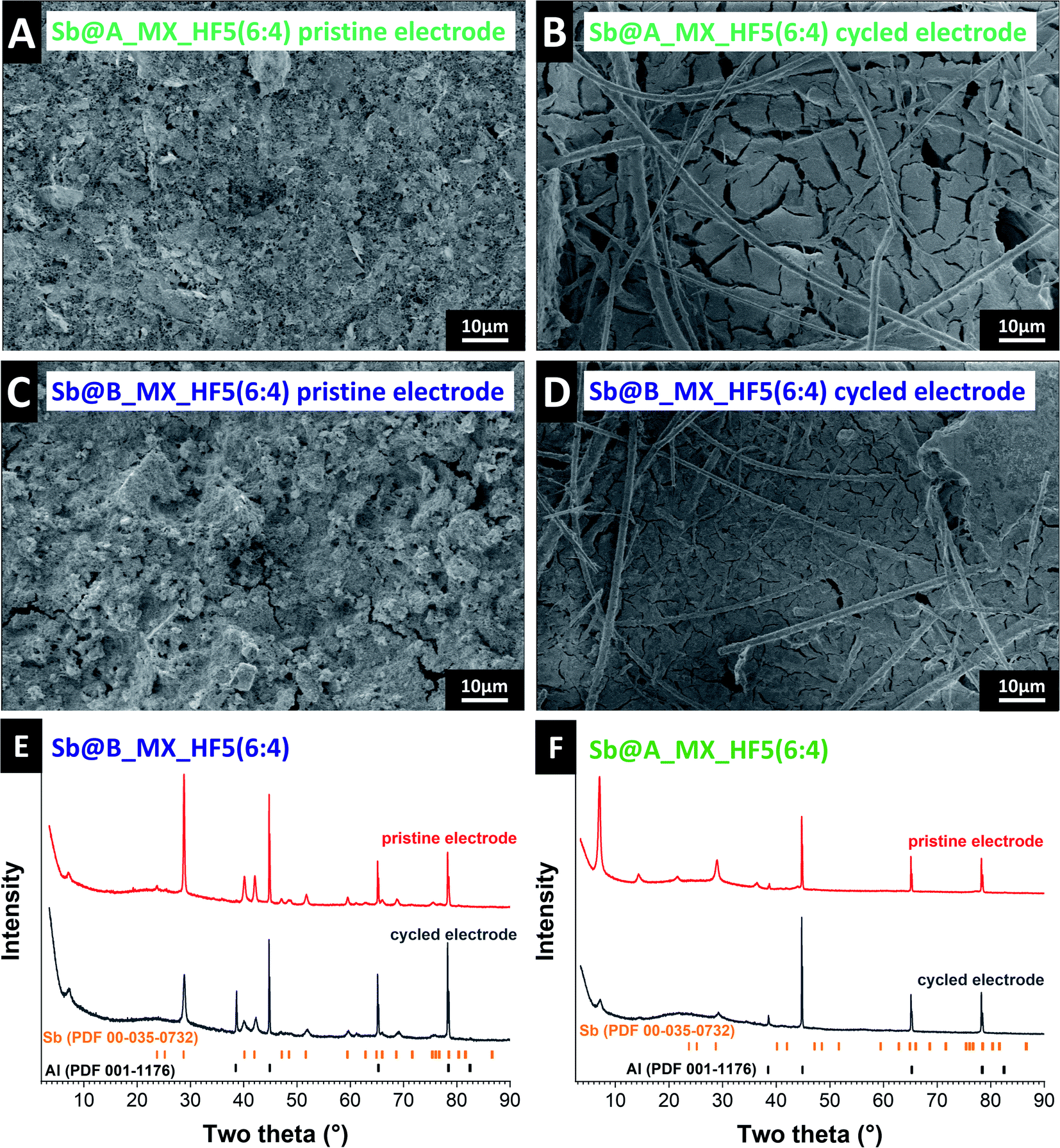 | ||
| Fig. 8 Scanning electron micrographs of the (A) pristine Sb@A_MX_HF5(6:4) electrode, (B) cycled Sb@A_MX_HF5(6:4) electrode, (C) pristine Sb@B_MX_HF5(6:4) electrode, and (D) cycled Sb@B_MX_HF5(6:4) electrode. X-ray diffraction pattern of (E) pristine and cycled Sb@B_MX_HF5(6:4) electrodes, (F) pristine and cycled Sb@A_MX_HF5(6:4) electrodes. | ||
 | ||
| Fig. 9 Graphical illustration and overview of the initial specific capacities and values after 50 cycles of cycling at a specific current of 0.1 A g−1 for different A@MXene composites or hybrid materials of the state-of-the-art systems in comparison to the values obtained in this work. Data from ref. 65 and 86–92. | ||
Post-mortem analysis shows that the promising electrochemical performance of the Sb@B_MX_HF5(6:4) electrode aligns with significantly fewer volume changes and fewer cracks of the electrodes. The best distribution of antimony particles, MXene layers, and conductive additive results in the best buffering of volume expansion, which is concluded in a good cycle and rate behavior. Optimized conductive paths allow homogeneous charge transfer on the surface of the antimony particles. Also seen in the electron micrographs is that the post mortem of the Sb@B_MX_HF5(6:4) electrode shows a homogeneous and flat electrode surface. It is suggested that this probably characterizes the SEI, which may have stabilized the electrochemical behavior compared to the other electrodes. Disordered parts and impurities could catalyze the chemical reactions, resulting in an improved SEI, better-buffering effects, and better interaction between the antimony material and MXene particles.45
The XRD patterns recorded ex situ (Fig. 8E and F) also confirm the statement of the reaction mechanism to Na3Sb and a larger fraction of amorphous antimony while cycling. Due to this, the antimony reflections become less intense, and new reflections appear. Also, the diffraction pattern of the Sb@A_MX_HF5(6:4) electrode displays a different intensity of the (002) reflection before and after cycling. This effect may be caused by the strong reflection of the aluminum current collector, which is more visible after cycling due to the cracks in the electrode. Despite the difficulty in detecting antimony in-between the layers of the MXene, it was possible to confirm that the antimony particles always react as in the proposed reaction mechanism.
4 Conclusions
MXenes' unique properties, including their high electrical conductivity and accessible interlayer space, make them highly attractive for numerous electrochemical applications, including alkali metal-ion batteries. So far, based only on ion intercalation, the specific capacity remains limited and mandates the exploration of combinations of MXene with other materials, such as alloying electrode materials. Antimony is a very promising anode candidate, which reacts in an alloying reaction with sodium to form Na3Sb delivering a high theoretical capacity of 660 mA h g−1. Yet, the major drawback of alloying materials is their large change in the volume during charging and discharging, which often leads to electrode cracking, pulverization, and poor electrochemical performance. An appropriate matrix can mitigate such a drawback, and we demonstrate the benefits (and limitations) of MXene/Sb electrodes.In our work, the influence of different types of MXenes, different synthesis routes, morphology, and different electrode compositions on electrochemical stability and longevity for use as an anode material in sodium-ion batteries was systematically investigated. The initial expansion of the MXene layers and the subsequent intercalation of the antimony nanoparticles in between the layers are disadvantageous properties of the hybrid electrodes as some parts of antimony seem not to be electrochemically accessible. The best performance is not triggered by the highest amount of antimony particles, the smallest nanoparticles, or the largest interlayer distance of the MXene but by the most homogeneous distribution of antimony and MXene while both components remain electrochemically addressable. With the best hybrid material, we obtained electrodes with a specific capacity of 450 mA h g−1 at 0.1 A g−1 and 365 mA h g−1 at 4 A g−1, with a capacity retention of around 96% after 100 cycles. In addition, the mechanism was investigated by in situ XRD and post mortem analysis, and an alloying reaction of antimony without side reactions was confirmed.
Author contributions
Stefanie Arnold: conceptualization, methodology, investigation, data curation, visualization, and writing – original draft. Antonio Gentile: conceptualization, investigation, data curation, and visualization. Yunjie Li: investigation, and writing – review & editing. Qingsong Wang: investigation, and writing – review & editing. Stefano Marchionna: resources, and writing – review & editing. Riccardo Ruffo: supervision, and writing – review & editing. Volker Presser: supervision, writing – review & editing, and funding acquisition.Conflicts of interest
There are no conflicts to declare.Acknowledgements
The INM authors thank Eduard Arzt (INM) for his continuing support. R. R. and A. G. acknowledge financial support from the Italian Ministry of University and Research (MIUR) through the Dipartimenti di Eccellenza – Materials for Energy. V. P. acknowledges funding of the DigiBatMat project (03XP0367A) within the competence cluster for battery cell production (ProZell) by the Federal Ministry of Education and Research (Bundesministerium für Bildung und Forschung). S. M., R. R., and A. G. acknowledge the financial support from Research Fund for the Italian Electrical System under the Contract Agreement between RSE S.p.A. and the Ministry of Economic Development – General Directorate for the Electricity Market, Renewable Energy and Energy Efficiency, Nuclear Energy in compliance with the Decree of April 16th, 2018. We also thank Ben Breitung (KIT) for his support, valuable comments, and discussions.References
- M. Li, J. Lu, Z. Chen and K. Amine, Adv. Mater., 2018, 30, 1800561 CrossRef PubMed.
- D. Kundu, E. Talaie, V. Duffort and L. F. Nazar, Angew. Chem., Int. Ed., 2015, 54, 3431–3448 CrossRef CAS PubMed.
- J. M. Tarascon, Nat. Chem., 2010, 2, 510 CrossRef CAS PubMed.
- M. D. Slater, D. Kim, E. Lee and C. S. Johnson, Adv. Funct. Mater., 2013, 23, 947–958 CrossRef CAS.
- V. Palomares, P. Serras, I. Villaluenga, K. B. Hueso, J. Carretero-González and T. Rojo, Energy Environ. Sci., 2012, 5, 5884–5901 RSC.
- M. Dahbi, N. Yabuuchi, K. Kubota, K. Tokiwa and S. Komaba, Phys. Chem. Chem. Phys., 2014, 16, 15007–15028 RSC.
- H. Buqa, D. Goers, M. Holzapfel, M. E. Spahr and P. Novák, J. Electrochem. Soc., 2005, 152, A474 CrossRef CAS.
- B. Simon, S. Flandrois, K. Guerin, A. Fevrier-Bouvier, I. Teulat and P. Biensan, J. Power Sources, 1999, 81–82, 312–316 CrossRef CAS.
- D. A. Stevens and J. R. Dahn, J. Electrochem. Soc., 2001, 148, A803 CrossRef CAS.
- Y. Li, S. Xu, X. Wu, J. Yu, Y. Wang, Y.-S. Hu, H. Li, L. Chen and X. Huang, J. Mater. Chem. A, 2015, 3, 71–77 RSC.
- S. Komaba, W. Murata, T. Ishikawa, N. Yabuuchi, T. Ozeki, T. Nakayama, A. Ogata, K. Gotoh and K. Fujiwara, Adv. Funct. Mater., 2011, 21, 3859–3867 CrossRef CAS.
- M. M. Doeff, Y. Ma, S. J. Visco and L. C. De Jonghe, J. Electrochem. Soc., 1993, 140, L169–L170 CrossRef CAS.
- S. Fleischmann, J. B. Mitchell, R. Wang, C. Zhan, D.-e. Jiang, V. Presser and V. Augustyn, Chem. Rev., 2020, 120, 6738–6782 CrossRef CAS PubMed.
- X. Yu, H. Pan, W. Wan, C. Ma, J. Bai, Q. Meng, S. N. Ehrlich, Y.-S. Hu and X.-Q. Yang, Nano Lett., 2013, 13, 4721–4727 CrossRef CAS PubMed.
- Y. Sun, L. Zhao, H. Pan, X. Lu, L. Gu, Y.-S. Hu, H. Li, M. Armand, Y. Ikuhara and L. Chen, Nat. Commun., 2013, 4, 1–10 Search PubMed.
- Z. Liang, P. Hui-Lin, H. Yong-Sheng, L. Hong and C. Li-Quan, Chin. Phys. B, 2012, 21, 028201 CrossRef.
- J. P. Huang, D. D. Yuan, H. Z. Zhang, Y. L. Cao, G. R. Li, H. X. Yang and X. P. Gao, RSC Adv., 2013, 3, 12593–12597 RSC.
- P. Senguttuvan, G. Rousse, V. Seznec, J.-M. Tarascon and M. R. Palacín, Chem. Mater., 2011, 23, 4109–4111 CrossRef CAS.
- Y. Kim, K. H. Ha, S. M. Oh and K. T. Lee, Chem. –Eur. J., 2014, 20, 11980–11992 CrossRef CAS PubMed.
- M.-S. Balogun, Y. Luo, W. Qiu, P. Liu and Y. Tong, Carbon, 2016, 98, 162–178 CrossRef CAS.
- M. Lao, Y. Zhang, W. Luo, Q. Yan, W. Sun and S. X. Dou, Adv. Mater., 2017, 29, 1700622 CrossRef PubMed.
- E. Edison, S. Sreejith, C. T. Lim and S. Madhavi, Sustainable Energy Fuels, 2018, 2, 2567–2582 RSC.
- W. Brehm, J. R. Buchheim and P. Adelhelm, Energy Technol., 2019, 7, 1900389 CrossRef CAS.
- L. Baggetto, J. K. Keum, J. F. Browning and G. M. Veith, Electrochem. Commun., 2013, 34, 41–44 CrossRef CAS.
- H. Zhu, Z. Jia, Y. Chen, N. Weadock, J. Wan, O. Vaaland, X. Han, T. Li and L. Hu, Nano Lett., 2013, 13, 3093–3100 CrossRef CAS PubMed.
- L. D. Ellis, B. N. Wilkes, T. D. Hatchard and M. N. Obrovac, J. Electrochem. Soc., 2014, 161, A416–A421 CrossRef CAS.
- J. Qian, X. Wu, Y. Cao, X. Ai and H. Yang, Angew. Chem., Int. Ed., 2013, 125, 4731–4734 CrossRef.
- M. He, K. Kravchyk, M. Walter and M. V. Kovalenko, Nano Lett., 2014, 14, 1255–1262 CrossRef CAS PubMed.
- J. B. Goodenough and Y. Kim, Chem. Mater., 2010, 22, 587–603 CrossRef CAS.
- L. Bodenes, A. Darwiche, L. Monconduit and H. Martinez, J. Power Sources, 2015, 273, 14–24 CrossRef CAS.
- A. Darwiche, L. Bodenes, L. Madec, L. Monconduit and H. Martinez, Electrochim. Acta, 2016, 207, 284–292 CrossRef CAS.
- L. Ji, M. Gu, Y. Shao, X. Li, M. H. Engelhard, B. W. Arey, W. Wang, Z. Nie, J. Xiao, C. Wang, J. G. Zhang and J. Liu, Adv. Mater., 2014, 26, 2901–2908 CrossRef CAS PubMed.
- S. Komaba, T. Ishikawa, N. Yabuuchi, W. Murata, A. Ito and Y. Ohsawa, ACS Appl. Energy Mater., 2011, 3, 4165–4168 CrossRef CAS PubMed.
- V. Winkler, G. Kilibarda, S. Schlabach, D. V. Szabó, T. Hanemann and M. Bruns, J. Phys. Chem. C, 2016, 120, 24706–24714 CrossRef CAS.
- A. Darwiche, C. Marino, M. T. Sougrati, B. Fraisse, L. Stievano and L. Monconduit, J. Am. Chem. Soc., 2012, 134, 20805–20811 CrossRef CAS PubMed.
- H. Hou, M. Jing, Y. Yang, Y. Zhang, W. Song, X. Yang, J. Chen, Q. Chen and X. Ji, J. Power Sources, 2015, 284, 227–235 CrossRef CAS.
- L. Wu, H. Lu, L. Xiao, X. Ai, H. Yang and Y. Cao, J. Mater. Chem. A, 2015, 3, 5708–5713 RSC.
- V. L. Chevrier and G. Ceder, J. Electrochem. Soc., 2011, 158, A1011 CrossRef CAS.
- M. Widmaier, N. Jäckel, M. Zeiger, M. Abuzarli, C. Engel, L. Bommer and V. Presser, Electrochim. Acta, 2017, 247, 1006–1018 CrossRef CAS.
- M. Widmaier, K. Pfeifer, L. Bommer and V. Presser, Batteries Supercaps, 2018, 1, 11–26 CrossRef CAS.
- C. Li, A. Sarapulova, K. Pfeifer and S. Dsoke, ChemSusChem, 2020, 13, 986–995 CrossRef CAS PubMed.
- C. Cui, J. Xu, Y. Zhang, Z. Wei, M. Mao, X. Lian, S. Wang, C. Yang, X. Fan and J. Ma, Nano Lett., 2018, 19, 538–544 CrossRef PubMed.
- L. Wu, X. Hu, J. Qian, F. Pei, F. Wu, R. Mao, X. Ai, H. Yang and Y. Cao, Energy Environ. Sci., 2014, 7, 323–328 RSC.
- Y. Zhu, X. Han, Y. Xu, Y. Liu, S. Zheng, K. Xu, L. Hu and C. Wang, ACS Nano, 2013, 7, 6378–6386 CrossRef CAS PubMed.
- K. Pfeifer, S. Arnold, Ö. Budak, X. Luo, V. Presser, H. Ehrenberg and S. Dsoke, J. Mater. Chem. A, 2020, 8, 6092–6104 RSC.
- M. Naguib, M. Kurtoglu, V. Presser, J. Lu, J. Niu, M. Heon, L. Hultman, Y. Gogotsi and M. W. Barsoum, Adv. Mater., 2011, 23, 4248–4253 CrossRef CAS PubMed.
- M. Naguib, J. Come, B. Dyatkin, V. Presser, P.-L. Taberna, P. Simon, M. W. Barsoum and Y. Gogotsi, Electrochem. Commun., 2012, 16, 61–64 CrossRef CAS.
- B. Anasori, M. R. Lukatskaya and Y. Gogotsi, Nat. Rev. Mater., 2017, 2, 16098 CrossRef CAS.
- M. Naguib, M. W. Barsoum and Y. Gogotsi, Adv. Mater., 2021, 33, 2103393 CrossRef CAS PubMed.
- E. Yang, H. Ji, J. Kim, H. Kim and Y. Jung, Phys. Chem. Chem. Phys., 2015, 17, 5000–5005 RSC.
- D. Er, J. Li, M. Naguib, Y. Gogotsi and V. B. Shenoy, ACS Appl. Energy Mater., 2014, 6, 11173–11179 CrossRef CAS PubMed.
- S. Kajiyama, L. Szabova, K. Sodeyama, H. Iinuma, R. Morita, K. Gotoh, Y. Tateyama, M. Okubo and A. Yamada, ACS Nano, 2016, 10, 3334–3341 CrossRef CAS PubMed.
- A. Gentile, C. Ferrara, S. Tosoni, M. Balordi, S. Marchionna, F. Cernuschi, M. H. Kim, H. W. Lee and R. Ruffo, Small Methods, 2020, 4, 2000314 CrossRef CAS.
- M. K. Aslam, T. S. AlGarni, M. S. Javed, S. S. A. Shah, S. Hussain and M. Xu, J. Energy Storage, 2021, 37, 102478 CrossRef.
- M. K. Aslam, Y. Niu and M. Xu, Adv. Energy Mater., 2020, 11, 2000681 CrossRef.
- H. Riazi, G. Taghizadeh and M. Soroush, ACS Omega, 2021, 6, 11103–11112 CrossRef CAS PubMed.
- J. K. Im, E. J. Sohn, S. Kim, M. Jang, A. Son, K.-D. Zoh and Y. Yoon, Chemosphere, 2021, 270, 129478 CrossRef CAS PubMed.
- A. Zhang, R. Liu, J. Tian, W. Huang and J. Liu, Chem. –Eur. J., 2020, 26, 6342–6359 CrossRef CAS PubMed.
- J. Zhou, J. Yu, L. Shi, Z. Wang, H. Liu, B. Yang, C. Li, C. Zhu and J. Xu, Small, 2018, 14, 1803786 CrossRef PubMed.
- K. Ma, H. Jiang, Y. Hu and C. Li, Adv. Funct. Mater., 2018, 28, 1804306 CrossRef.
- J. Yu, J. Zhou, P. Yao, J. Huang, W. Sun, C. Zhu and J. Xu, J. Power Sources, 2019, 440, 227150 CrossRef CAS.
- S. Husmann, M. Torkamanzadeh, K. Liang, A. Majed, C. Dun, J. J. Urban, M. Naguib and V. Presser, Adv. Mater. Interfaces, 2022, 2102185 CrossRef.
- M. Naguib, O. Mashtalir, M. R. Lukatskaya, B. Dyatkin, C. Zhang, V. Presser, Y. Gogotsi and M. W. Barsoum, Chem. Commun., 2014, 50, 7420–7423 RSC.
- Z. Ling, E. Ren Chang, M.-Q. Zhao, J. Yang, M. Giammarco James, J. Qiu, W. Barsoum Michel and Y. Gogotsi, Proc. Natl. Acad. Sci. U. S. A., 2014, 111, 16676–16681 CrossRef CAS PubMed.
- H. Chen, N. Chen, M. Zhang, M. Li, Y. Gao, C. Wang, G. Chen and F. Du, Nanotechnol, 2019, 30, 134001 CrossRef CAS PubMed.
- X. Guo, H. Gao, S. Wang, G. Yang, X. Zhang, J. Zhang, H. Liu and G. Wang, Nano Lett., 2022, 22, 1225–1232 CrossRef CAS PubMed.
- H. Gao, X. Guo, S. Wang, F. Zhang, H. Liu and G. Wang, EcoMat, 2020, 2, e12027 CrossRef CAS.
- F. Zhang, Z. Jia, C. Wang, A. Feng, K. Wang, T. Hou, J. Liu, Y. Zhang and G. Wu, Energy, 2020, 195, 117047 CrossRef CAS.
- S. Arnold, L. Wang, Ö. Budak, M. Aslan, P. Srimuk and V. Presser, J. Mater. Chem. A, 2021, 9, 585–596 RSC.
- D. Weingarth, M. Zeiger, N. Jäckel, M. Aslan, G. Feng and V. Presser, Adv. Energy Mater., 2014, 4, 1400316 CrossRef.
- J. Qian, Y. Chen, L. Wu, Y. Cao, X. Ai and H. Yang, Chem. Commun., 2012, 48, 7070–7072 RSC.
- Y.-X. Wang, Y.-G. Lim, M.-S. Park, S.-L. Chou, J. H. Kim, H.-K. Liu, S.-X. Dou and Y.-J. Kim, J. Mater. Chem. A, 2014, 2, 529–534 RSC.
- A. Ponrouch, A. R. Goñi and M. R. Palacín, Electrochem. Commun., 2013, 27, 85–88 CrossRef CAS.
- A. Ponrouch, D. Monti, A. Boschin, B. Steen, P. Johansson and M. R. Palacín, J. Mater. Chem. A, 2015, 3, 22–42 RSC.
- V. Simone, L. Lecarme, L. Simonin and S. Martinet, J. Electrochem. Soc., 2016, 164, A145–A150 CrossRef.
- A. Rozmysłowska-Wojciechowska, J. Mitrzak, A. Szuplewska, M. Chudy, J. Woźniak, M. Petrus, T. Wojciechowski, A. S. Vasilchenko and A. M. Jastrzębska, Materials, 2020, 13, 2347 CrossRef PubMed.
- G. R. Berdiyorov, Appl. Surf. Sci., 2015, 359, 153–157 CrossRef CAS.
- X. Zhou, Z. Dai, J. Bao and Y.-G. Guo, J. Mater. Chem. A, 2013, 1, 13727–13731 RSC.
- S. Pruneanu, E. Veress, I. Marian and L. Oniciu, Mater. Sci., 1999, 34, 2733–2739 CAS.
- S. Fleischmann, Y. Zhang, X. Wang, P. T. Cummings, J. Wu, P. Simon, Y. Gogotsi, V. Presser and V. Augustyn, Nat. Energy, 2022, 7, 222–228 CrossRef.
- P. R. Abel, Y.-M. Lin, T. de Souza, C.-Y. Chou, A. Gupta, J. B. Goodenough, G. S. Hwang, A. Heller and C. B. Mullins, J. Phys. Chem. C, 2013, 117, 18885–18890 CrossRef CAS.
- Y. Kim, Y. Park, A. Choi, N. S. Choi, J. Kim, J. Lee, J. H. Ryu, S. M. Oh and K. T. Lee, Adv. Mater., 2013, 25, 3045–3049 CrossRef CAS PubMed.
- R. Meng, J. Huang, Y. Feng, L. Zu, C. Peng, L. Zheng, L. Zheng, Z. Chen, G. Liu, B. Chen, Y. Mi and J. Yang, Adv. Energy Mater., 2018, 8, 1801514 CrossRef.
- Q. Li, W. Zhang, J. Peng, W. Zhang, Z. Liang, J. Wu, J. Feng, H. Li and S. Huang, ACS Nano, 2021, 15, 15104–15113 CrossRef CAS PubMed.
- X. Ou, C. Yang, X. Xiong, F. Zheng, Q. Pan, C. Jin, M. Liu and K. Huang, Adv. Funct. Mater., 2017, 27, 1606242 CrossRef.
- Y. Wu, P. Nie, J. Jiang, B. Ding, H. Dou and X. Zhang, ChemElectroChem, 2017, 4, 1560–1565 CrossRef CAS.
- Y. Zhang, B. Guo, L. Hu, Q. Xu, Y. Li, D. Liu and M. Xu, J. Alloys Compd., 2018, 732, 448–453 CrossRef CAS.
- H. Li, A. Liu, X. Ren, Y. Yang, L. Gao, M. Fan and T. Ma, Nanoscale, 2019, 11, 19862–19869 RSC.
- L. Gou, W. Jing, Y. Li, M. Wang, S. Hu, H. Wang and Y.-B. He, ACS Appl. Energy Mater., 2021, 4, 7268–7277 CrossRef CAS.
- Y. Wu, P. Nie, L. Wu, H. Dou and X. Zhang, Chem. Eng. J., 2018, 334, 932–938 CrossRef CAS.
- J. Ding, C. Tang, G. Zhu, F. He, A. Du, M. Wu and H. Zhang, Mater. Chem. Front, 2021, 5, 825–833 RSC.
- X. Guo, X. Xie, S. Choi, Y. Zhao, H. Liu, C. Wang, S. Chang and G. Wang, J. Mater. Chem. A, 2017, 5, 12445–12452 RSC.
- H. Hou, Y. Yang, Y. Zhu, M. Jing, C. Pan, L. Fang, W. Song, X. Yang and X. Ji, Electrochim. Acta, 2014, 146, 328–334 CrossRef CAS.
Footnote |
| † Electronic supplementary information (ESI) available: Supplementary X-ray diffraction patterns, supplementary scanning electron micrographs, particle size distribution of synthesized Sb particles, supplementary electrochemical characterization, and graphical illustration performance comparison of all obtained hybrid materials. See DOI: 10.1039/d2ta00542e |
| This journal is © The Royal Society of Chemistry 2022 |