Integrating recyclable polymers into thermoelectric devices for green electronics

Jie Zheng *ab, Samantha Faye Duran Solco a, Claris Jie Ee Wong ac, Seng Ann Sia ad, Xian Yi Tan ad, Jing Cao a, Jayven Chee Chuan Yeo a, Weili Yan e, Qiang Zhu a, Qingyu Yan d, Jing Wu a, Ady Suwardi *ac and Zibiao Li *abc
aInstitute of Materials Research and Engineering, Agency for Science, Technology and Research, #08-03, 2 Fusionopolis Way, Singapore 138634. E-mail: ady_suwardi@imre.a-star.edu.sg
bInstitute of Sustainability for Chemicals, Energy and Environment (ISCE2), A*STAR, 1 Pesek Road, Jurong Island, 627833 Singapore. E-mail: zheng_jie@imre.a-star.edu.sg; lizb@imre.a-star.edu.sg
cDepartment of Materials Science and Engineering, National University of Singapore, Singapore 117575
dSchool of Materials Science and Engineering, Nanyang Technological University, Singapore 639798
eNTU Corporate Lab, Nanyang Technological University, 50 Nanyang Avenue, Singapore 639798

Received 15th January 2022 , Accepted 21st April 2022

First published on 21st April 2022


Abstract

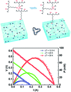
Electronic waste (e-waste) recycling is one of the central frameworks of the circular economy. However, most e-wastes consist of both organic and inorganic components, which significantly limits their clean separation and recycling for repurposing. Herein, we demonstrate the use of a recyclable polymer (vitrimer) as the encapsulation matrix to construct a recyclable thermoelectric device. An epoxy vitrimer containing dynamic silyl ether linkage was employed as the device encapsulation to provide mechanical support, conformability to surfaces, and more importantly, reprocessability. Benefiting from these features, the resultant vitrimer encapsulated thermoelectric device not only showed an enhanced power generation ability relative to the parent device, but also exhibited new alluring characteristics, such as strong mechanical properties, operability under deformed conditions, clean separation capability, and recyclability. Remarkably, the refabricated device retains its power generation performance, demonstrating the reliability of this method. The strategy reported here can be generally applied to other electronic devices, therefore contributing towards sustainable and circular utilization of resources.


Introduction

Electronic devices are becoming more ubiquitous in the current rapid technological development era.1–4 With an increasing level of complexity, many modern electronics consist of both organic and inorganic components. Such a hybrid composition, however, makes the resulting electronic wastes (e-wastes) arduous to sort and separate, let alone recycle for remanufacturing. In 2021, approximately 50 million metric tons (Mt) of e-waste ended up in landfills and/or the natural environment, resulting in severe environmental consequences, and countless investment expenditures. Moreover, the accumulated e-waste amount is continuously growing and is projected to reach 70 Mt by 2027. Therefore, designing electronic devices with facile separation ability and recyclability is a critical challenge for the realization of a circular economy in this area.5,6

Thermoset plastics are traditionally employed in many parts of electronic devices. They are three-dimensional (3D) interconnected polymer networks that consist of permanently crosslinked polymer chains. This strong covalent connection character allows thermosets to exhibit excellent mechanical robustness, thermal stability, and chemical/creep resistance, making them materials of choice for different end applications. However, this structural feature compromises their reprocessing/recycling/reshaping, resulting in serious environmental concerns. In the case of e-waste containing thermosets, this feature renders e-waste recycling even more difficult. It is thereby necessary to develop new materials with good recyclability to mitigate the environmental devastation caused by plastic-related waste, including e-waste.

The emergence of dynamic covalent polymer networks (DCPNs) serves as an extraordinary solution to tackle these problems.7–9 They are living polymer networks derived from the exchangeable covalent connection, thus allowing reprocessing while simultaneously retaining the benefits of thermosets. They can behave as classical thermosets under service conditions, while the rearrangeable network topologies enable them to be reprocessed under certain external stimuli, such as heat, light, pH, and solvent. Vitrimers are important DCPNs with the dynamic associative mechanism, in which chemical bonds break and reform via a single step simultaneously, thereby enabling them to maintain a constant crosslinking density throughout the exchange process (Scheme 1).10–12 Encouraged by the rapid development of sustainable society, different types of reversible chemical reactions have been reported based on, for example, transesterification,13,14 olefin metathesis,15 dioxaborolane metathesis,16 and silyl ether exchange.17,18 In contrast to dissociative DCPNs, vitrimers offer superior dimensional stability and creep resistance, thus obtaining increasing attention in various real engineering applications, such as shape-memory materials, self-healing materials, and material-reinforced composites.7 However, few examples have exploited the potential of vitrimers for green electronic device fabrication. Two excellent examples are the pioneering studies by Xiao and coworkers who exploited dynamic polyimine to encapsulate commercial thermoelectric (TE) legs using liquid metal as interconnects to construct recyclable, healable, and stretchable thermoelectric generators (TEGs).19,20 Besides, another elegant study was by Wang and coworkers who investigated a jigsaw puzzle-like healable triboelectric nanogenerator through encapsulating a silver nanowire percolation network via a dynamic disulfide bond-based vitrimeric material.21


image file: d2ta00386d-s1.tif
Scheme 1 Schematic illustration of the reprocessing of vitrimers via a dynamic associative mechanism. The crosslink density of these materials is almost constant during the reprocess.

Motivated by the versatility of DCPNs, we explore the clean separation and recyclability of polymer and metal/semiconductor constituents from the green electronic device reported in this study. For this purpose, a flexible TEG embedded in a DCPN was prepared and tested. TEGs were chosen owing to their technological importance, and their robustness against wear and tear.22–24 They can be used to harvest electrical energy from environmental waste heat. Vice versa, thermoelectrics (TEs) can also be used to convert electricity into heat pumps, serving as solid state refrigeration. In recent years, with the rapid progress of flexible electronics, flexible TEGs have become ever more crucial to providing an energy source for these flexible devices.25–35

A typical TEG encompasses alternately connected p- and n-type TE legs connected by metal electrodes (i.e. copper). The performance of a TEG is directly proportional to its figure of merit (zT = S2σT/κ, where S, σ, and κ denote the Seebeck coefficient, electrical conductivity, and thermal conductivity, respectively). It is not surprising that the majority of efforts in thermoelectric materials research have been focused on maximizing zT.36–41 However, besides zT, the overall performance of a TEG also depends on other factors such as the quality of electrical and thermal contacts.42–48 Therefore, the device encapsulation matrix plays a key role, not only in supporting the mechanical robustness and imparting flexibility but also as a filler for the thermal and electrical insulation of the final device.49–51 Traditionally, once these devices are integrated, it is very tedious to separate the flexible polymer matrix from the inorganic TE legs. For instance, most conventional TEGs are encapsulated with rigid thermoset materials, such as crosslinked polydimethylsiloxane, which are difficult to recycle, consequently resulting in e-waste concerns after usage.

To date, very limited studies have demonstrated flexible TEGs with excellent self-healability and recyclability by combining thermoelectric chips and DCPNs.19,20 In these studies, dynamic covalent polyimine has been used to connect thermoelectric materials and liquid-metal electrical wiring to obtain flexible TEGs with high open-circuit voltage. However, these are only performed on thin film thermoelectric legs. Therefore, more efforts are needed to design and fabricate new DCPN encapsulated TEGs with enhanced performance and recyclability due to their great potential for the development of the circular materials economy.

In this work, we fabricate a recyclable and re-manufacturable TEG device (i.e. BAA-TEG) by integrating TE legs with an epoxy vitrimer matrix containing dynamic silyl ether bonds (BAA) (Scheme 2). Like our initial hypothesis, the vitrimer encapsulation exhibited robust mechanical performance and low thermal diffusivity, providing strong support and efficient thermal insulation for the resulting device. Compared to the bare TEG assembly, the vitrimer encapsulated TEG system exhibited a higher power generation performance with more than 70 mW for temperature gradients below 30 K, enough to power a small LED. Furthermore, unlike the conventional unrecyclable TEG systems, this unique TEG system was able to be separated simply to recover precious TE legs for reuse. Importantly, the refabricated flexible TEG device showed full recovery of the energy harvesting performance, verifying the effectiveness of this system. The strategy shown in this work can be used as a guide for future recyclable thermoelectric device construction, paving the way for the development of other smart wearable electronics and their recycling at the end of their lifespan.


image file: d2ta00386d-s2.tif
Scheme 2 Schematic illustration of the fabrication of the vitrimer encapsulated TEG (named the BAA-TEG) (inset figure is the dynamic structure of the vitrimer network showing repeated reprocessability).

Results and discussion

Synthesis and characterization of the epoxy vitrimer

The synthesis of the epoxy-based vitrimer (BAA) with an exchangeable silyl ether bond is shown in Scheme S1 (ESI). Because of the high toughness and low viscosity, a commercially available starting material, an epoxy monomer (bisphenol A propoxylate diglycidyl ether, BAPDE) was selected to cure with 6-amino-1-hexanol (AHO), and 3-aminopropyltriethoxysilane (APTS) via facile one-pot and catalyst-free synthesis. The progress of this reaction was monitored by high temperature 1H NMR and the concentrations of epoxy groups in BAPDE (3.01–3.08 ppm) were determined based on the integrals of the NMR peaks (Fig. S1a and b in ESI). It shows that for the reaction at 60 °C, the concentration of epoxy groups (blue shadow) gradually decreased over time, while that of the product (red shadow) increased, and nearly complete monomer conversion was achieved after around 12 h. The structure of BAA was confirmed using the FTIR technique. FTIR spectra of BAPDE and BAA are shown in Fig. S1c (ESI). Compared with the FTIR spectrum of the BAPDE monomer, the disappearance of bands corresponding to the epoxy group at 902 cm−1 (C–O stretching of the oxirane ring) and 3057 cm−1 (C–H stretching of the oxirane ring) was observed in that of the resultant BAA, demonstrating the full conversion of the monomer. Besides, the synthesized BAA has a new broad peak around 3400 cm−1 which belonged to the hydroxy group. A new absorption peak at 1000 cm−1 ascribing to –O–Si– was also observed, demonstrating that the silyl ether bond was successfully incorporated into the network.

Thermogravimetric analysis (TGA) and differential scanning calorimetry (DSC) were utilized to investigate the thermal stability of BAA. The initial thermal decomposition temperature (Tdi, temperature at 5% weight loss) of BAA is around 298 °C (Fig. S2, black line, in the ESI) and no melting peak was observed (Fig. S3, black line, in the ESI), showing the good thermal stability of the synthesized crosslinked polymer. This is attributed to the robustness of the silyl ether linkage in the BAA network.

The storage modulus and glass transition temperature (Tg) of BAA were investigated by dynamic mechanical analysis (DMA). The storage modulus of BAA as a function of temperature is shown in Fig. 1a, which reveals that BAA has a relatively high storage modulus of 2500 MPa below Tg (41 °C) and a clear rubber plateau above Tg, indicating the crosslinked structure of BAA. The dynamic bond exchange feature of BAA was evaluated by stress relaxation analyses at elevated temperatures (70, 90, 110, and 120 °C, respectively) via DMA as well. As shown in Fig. 1b, the stress relaxation modulus decreased exponentially over time, indicating that the crosslinked polymer was a vitrimer capable of relaxing stress for an extended time due to the dynamic silyl ether exchange reaction. According to the Maxwell equation for viscoelastic fluids, the relaxation time (τ*) was determined as the time required to relax 1/e (36.7%) of the initial stress. With the increase in temperature, the exchange rate becomes faster, and the obtained τ* ranges from 736 s at 70 °C to 51 s at 120 °C. The activation energy (Ea) of the silyl ether exchange reaction was calculated to be 55 kJ mol−1 fitted using Arrhenius' law (Fig. 1c). This result is consistent with previous reports on other silyl ether based vitrimeric materials.52


image file: d2ta00386d-f1.tif
Fig. 1 (a) Dependence of the storage modulus and tan delta (δ) versus temperature for BAA. (b) Stress relaxation curves of BAA at different temperatures. (c) Fitting of the relaxation time to Arrhenius' equation. (d) Tensile stress–strain curves of the original, first reprocessed, and second reprocessed BAA material. (e) Photographs demonstrating the recycling of BAA. (f) Photo illustration of the BAA vitrimer in TBAF THF solution at 60 °C for 0 h (left) and 6 h (right). (g) Photo illustration of the BAA vitrimer in THF solution at 60 °C for 0 h (left) and 48 h (right).

The dynamic nature of silyl ether bonds has been confirmed via the small-molecule model reaction (Fig. S4 in ESI). The as-designed model reaction was performed through trans-methoxylation of phenol to methoxytrimethylsilane and proton change (before and after the reaction) was recorded using 1H NMR. Fig. S4 shows the 1H NMR spectra of the reaction at time zero and at 12 h at 100 °C. Compared with the spectrum of the original equimolar mixture of model compounds, at 12 h, the methoxysilane resonances (blue shadow in Fig. S4 in the ESI) obviously reduce, and a newborn peak belonging to the methanol hydroxyl group appears (red shadow in Fig. S4 in the ESI), verifying the dynamic nature of this designed silyl ether bond reaction.

Fig. 1d shows the tensile stress–strain curves of BAA with a large fracture strain of around 160%, indicating the good flexibility of the resultant vitrimeric polymer. Besides, the BAA network is capable of being reprocessed due to the dynamic silyl ether linkage. After failure, the BAA sample was cut into small pieces and subsequently hot-pressed at 120 °C, 10 bar for 10 min to fully reform the polymer network (Fig. 1d and e). The tensile tests indicate that the mechanical properties of BAA are almost fully recovered after the reprocessing, suggesting the retention of the network integrity (Fig. 1d). The slightly increased modulus might be from the aging of the samples during the reprocess. FTIR confirms that there was no significant change that occurred during the reprocessing of the sample (Fig. S5, pink and red lines, in the ESI). Besides, the BAA network also displays on-demand self-healing behavior ascribed to the reorganization of the network structure. To visually demonstrate the self-healing properties of the polymer, a dog-bone shaped specimen was broken into 3 parts, and then the crack surfaces were put together followed by treating at 60 °C for 20 min. It was shown that the damaged specimen can be easily healed back (Fig. S6 in the ESI).

Furthermore, two other parameters, i.e. thermal conductivity and degradability, are also essential for recyclable TEG devices. Based on the thermoelectric device efficiency formula, maintaining a high temperature difference is essential for achieving high efficiency. In this regard, polymers with low thermal conductivity enable a robust thermal gradient between the hot and cold ends, thus ensuring the device's thermoelectric performance. According to the temperature wave analysis, the thermal conductivity of the BAA polymer was <0.5 W mK−1 at room temperature, much lower than that of the thermoelectric legs, making it suitable as the matrix. To achieve the recycling of TEG legs, a clean separation of TEG devices by decomposing polymer encapsulation is necessary. It is known that the fluoride reagent (i.e. tetrabutylammonium fluoride, TBAF) has been used to selectively remove silyl ether protecting groups.53 As such, it is hypothesized that TBAF could be employed to cleave the silyl ether linkage of the BAA network to achieve soluble linear polymers to realize the separation of the TEG legs and polymer matrix. For the demonstration, a piece of the BAA specimen was immersed in THF solution at 60 °C. With the addition of TBAF, BAA was completely dissolved after 1 h (Fig. 1f), while the specimen remained intact after 48 h in the absence of TBAF (Fig. 1g). This means that BAA networks can be selectively decomposed by using TBAF solution, indicating the separability of the subsequent thermoelectric device based on BAA encapsulation. Apart from THF, we also probed the vitrimer solubility in other TBAF solutions, such as ethanol and water. However, the vitrimer remained intact after 48 h at 60 °C in the latter solutions (Fig. S7). On the other hand, TE legs show good resistance in THF. Thus, TBAF THF solution was selected to degrade the TEG in the following experiment. We attribute the degradation ability of the vitrimer to the silyl ether linkage in the network. To confirm that, a controlled experiment was carried out. We attempted the degradation of a reference thermoset network (named BTA) generated via the reaction between BAPDE and tris(2-aminoethyl)amine (TAA) (Fig. S8a and b). A mixture of BTA (5 wt%) and TBAF THF (95 wt%) was heated at 60 °C for 48 h (Fig. S8c). The thermoset specimen remained intact, meaning that the TABF induced degradation of polymer networks did not occur for the reference thermoset. This result supports our hypothesis that the dynamic silyl ether linkage imparts the vitrimeric material with not only a rearrangeable profile but also degradability. A possible mechanism of the reaction between the silyl ether bond and TBAF is also given in Scheme S2 in the ESI. Interestingly, the degraded polymer can be reused to regenerate a new vitrimer. We purified the degraded polymer by removing TBAF in water and converted it into a new vitrimer via reacting with the crosslinker APTS (one of the starting materials) (Fig. S9f–h and Experimental section 2.7 in the ESI). According to the FTIR, TGA, and DSC results, the re-generated vitrimer exhibited similar structural (Fig. S5, blue line) and thermal properties (Fig. S2, blue line, and Fig. S3, blue line) in comparison to the original vitrimer, demonstrating the good recyclability of the degrading polymer matrix.

Consequently, the DMA, TGA, tensile test, thermal conductivity measurement, and degradation test demonstrated above suggest that the chemically recyclable and degradable BAA vitrimer with good thermal stability and low thermal diffusivity can be a good candidate for a flexible and recyclable thermoelectric device.

Characterization of the thermoelectric setup

The thermoelectric setup was based on Bi0.5Sb1.5Te3 as the p-type leg and Bi2Te2.7Se0.3 as the n-type leg and consists of 50 pairs of p–n legs connected by copper electrodes. To verify the materials properties of both the p-type and n-type legs, Fig. 2 shows the electronic and thermal transport of both materials. Fig. 2a shows the resistivity vs. temperature of both Bi0.5Sb1.5Te3 and Bi2Te2.7Se0.3. The temperature profile generally shows metallic behaviour, which is consistent with the degenerate level of the carrier concentration in the materials. At high temperatures (>400 K), the resistivity of Bi2Te2.7Se0.3 starts to decrease due to the onset of bipolar conduction, resulting in a higher carrier concentration. Fig. 2b shows the temperature profile of Seebeck coefficients for both legs, with values above 200 μV K−1, consistent with optimally doped values for Bi0.5Sb1.5Te3 and Bi2Te2.7Se0.3 from the literature. In addition, from the device point of view, the value of thermal conductivity of both the p and n legs must be close to ensure a uniform temperature gradient across the device. At around room temperature, the thermal conductivity of both Bi0.5Sb1.5Te3 and Bi2Te2.7Se0.3 lies at around 1 W mK−1, as shown in Fig. 2c. Lastly, zT as high as 1.0 and 0.7 were obtained for Bi0.5Sb1.5Te3 and Bi2Te2.7Se0.3, respectively.
image file: d2ta00386d-f2.tif
Fig. 2 Temperature dependent (a) electrical resistivity, (b) Seebeck coefficients, (c) thermal conductivity, and (d) zT of Bi0.5Sb1.5Te3 and Bi2Te2.7Se0.3.

Based on the electronic and thermal transport data, the ideal form factors for the device should be as close as possible to the following values:

 
image file: d2ta00386d-t1.tif(1)

Based on the data from Fig. 2, the ideal form factor should satisfy LnAp = 0.978 LpAn, which is pretty close to unity. In other words, the choice of using identical dimensions of 2 mm × 2 mm × 3 mm for both p type and n type legs is close to ideal considering the respective thermoelectric properties of both legs.

Characterization of the recyclable thermoelectric device

The developed vitrimer material (BAA) was utilized as a matrix to construct TEG devices. The target vitrimer encapsulated thermoelectric device (named the BAA-TEG) was fabricated by simply immersing the thermoelectric setup in the polymer solution and subsequently curing (Scheme 2, Fig. 3a, b and the ESI). In this BAA-TEG system, Bi0.5Sb1.5Te3 and Bi2Te2.7Se0.3 legs are immersed in the BAA matrix with a copper (Cu) layer soldered on the top and bottom of the TE legs for the thermal and electrical contacts. Leveraging the robust mechanical strength and flexibility of the BAA vitrimer support, the resulting BAA-TEG is easy to handle as a power generator. An attractive feature of this TEG system is the capability of recycling TE legs for remanufacturing, prolonging the lifetime of the device, and eventually decreasing the e-waste. At the end of its service lifespan, unlike the conventional TEG systems, this system enables clean separation of the metal and polymer parts to be realized by decomposing the polymer matrix. We immersed the BAA-TEG in TBAF THF solution at 60 °C for 8 h to completely degrade the polymer network, and subsequently obtained the bare TEG assembly (Fig. 3c and S9a–f), which can be used to fabricate a new device either by re-encapsulating with a new BAA matrix (half recycled BAA-TEG) (Fig. S10) or via the reuse of the degraded polymer with the addition of APTS as a crosslinker (fully recycled BAA-TEG) (Fig. 3d), albeit with some weight losses (73% weight is recovered) and discoloration.
image file: d2ta00386d-f3.tif
Fig. 3 Photo illustration of (a) the TE material assembly (50 couples), (b) original BAA-TEG, (c) recycled TE material assembly and degraded polymer solution, and (d) recycled BAA-TEG (photos of TEG cured at 80 °C).

A homemade setup was employed to investigate the power generation performance of the BAA-TEG. Fig. 4a shows the details of the generated open-circuit (V) and output power (P) as a function of current (I) at various temperature differences (10 K, 20 K, and 30 K). As can be seen, the output voltage V reaches over 0.6 V, and the device yields a maximal output power of 70 mW at a moderate level of temperature gradient (ΔT = 30 K) (Fig. 4a (hollow symbols)). The gradient in the I vs. V curve shown in Fig. 4a represents the total electrical resistance of the device, which is around 1.35 Ω, consistent with the electrical resistivity values of the respective legs (1.2 Ω) in Fig. 2. In addition, the recycled device performance does not show appreciable deterioration, as shown in the line plot in Fig. 4a. The power generated as a function of temperature gradient of both experimental and calculated data are shown in Fig. 4b. It is worth noting that the experimental power output is slightly lower compared to the theoretical values presumably due to the additional contact resistance between the thermoelectric legs and the copper contact. In addition, as mentioned above, despite acting as a mechanical support for the TEG assembly, vitrimer encapsulation also serves as a filler for thermal and electrical insulation for the thermoelectric device, enabling less thermal loss and imparting the resultant BAA-TEG with higher open-circuit voltage and total power output in comparison to its bare TE leg assembly, even under the bending condition (Fig. 4c and d). Furthermore, the BAA-TEG was also able to power a 100 mW LED lamp at a temperature difference ΔT of 35 K, showing the utility of the device (Fig. 4e).


image file: d2ta00386d-f4.tif
Fig. 4 (a) Output voltage and power as a function of current in the thermoelectric device at various temperature gradients. The hollow symbols represent the original device performance and line plot represents performance after recycling. (b) Output power density as a function of the temperature gradient of the encapsulated device. (c) LED powered by the device kept at a ΔT of 35 K. (d) Comparison of performance between the bare device, device under bending, and original encapsulated device at a ΔT of 30 K, demonstrating better thermal contact in the encapsulated device. (e) Comparison of the open circuit voltage and output power for the original encapsulated device, bare device, device under bending, and recycled device.

Besides power generation, thermoelectrics can also be used as cooling devices. Fig. 5a shows the temperature difference achieved as a function of current polarity and magnitude passed through the device. With respect to the top side, negative current (current moving from the bottom to the top side in the p-type leg and top to down in the n-type leg) corresponds to heating, as shown in Fig. 5b. In contrast, positive current (current moving from the top to the bottom side in the p-type leg, and from bottom to top in the n-type leg) corresponds to cooling, as shown in Fig. 5c. It is noteworthy that in cooling mode, beyond 5 A current, the magnitude of extra heat generated by Joule heating starts to be higher than the cooling through the Peltier effect, resulting in lower overall cooling (ΔT).


image file: d2ta00386d-f5.tif
Fig. 5 (a) Calculated resultant temperature gradient as a function of current through the device showing heating and cooling regions as the current polarity is reversed. Thermal imaging camera showing (b) heating mode and (c) cooling mode. Cooling temperature as high as 10 K can be achieved within a few s after 0.5 A current is passed through the device (ESI Video). (d) Cooling power as a function of current through the device at various temperature gradients ΔT. (e) COP (coefficient of performance) as a function of current for the device at various ΔT.

In terms of performance, higher cooling power can be achieved when the device is used at a lower temperature gradient (ΔT), as illustrated in Fig. 5d. In addition, it is noteworthy that the peak in cooling power in Fig. 5d is consistent with the upturn in ΔT in Fig. 5a. It can be inferred that the optimum current to achieve maximum cooling in this device is around 4.5 A. A more nuanced way of interpreting Fig. 5d is that at lower ΔT, there is more capacity for further cooling, and therefore higher cooling power.

Lastly, in terms of energy efficiency, the COP (coefficient of performance) is the commonly used metric. It is defined as the amount of cooling power achieved with respect to the amount of total energy input needed. Therefore, a high COP is desirable in any cooling device. For instance, a COP of 2 means that every 1 W of power consumption results in 2 W of cooling. Fig. 5e shows the COP of the device as a function of current at different ΔT. It is evident from the figure that a high COP can be achieved by optimizing current and lowering ΔT. In other words, it is much more energy efficient for the device to maintain lower temperature gradient as opposed to a high temperature gradient. For instance, for wearable applications to provide thermal comfort for humans, a moderate ΔT of 10 K is generally required. This corresponds to the COP of 2 with 1 A current passing through the device.

In conclusion, we demonstrated a flexible, deformable, and recyclable thermoelectric device for energy harvesting by integrating the dynamic vitrimer matrix based on an exchangeable silyl ether bond. This vitrimer encapsulation behaved as a robust support and an effective insulation filler for the resultant thermoelectric device. The developed BAA-TEG thermoelectric device offered superior mechanical strength and operation convenience over its bare TEG assembly counterpart. Additionally, the BAA-TEG displayed the improvement of thermal contact and thermal gradient maintenance, ensuring the higher power generation performances of more than 70 mW for a moderate temperature gradient below 30 K. Taking advantage of the cleavability of the silyl ether bond in the vitrimer material, we degraded the used thermoelectric device to regenerate the precious TEG assembly, which was employed to reprepare a new thermoelectric device with the full recovery of the thermoelectric properties, demonstrating the concept of the chemical recyclability of the thermoelectric material and the effectiveness of this system. The significance behind the recyclable thermoelectric device provides a facile and sustainable approach for power generation in flexible electronic systems. We believe that the adoption of smart polymers in thermoelectric devices may provide a new route for flexible device fabrication and promote e-waste recycling.

Conflicts of interest

There are no conflicts to declare.

Acknowledgements

A. S. would like to acknowledge the Career Development Fund (CDF) C210112022 and Science and Engineering Research Council Sustainable Hybrid Lighting System for Controlled Environment Agriculture programme: A19D9a0096. This work was also financially supported by the Agency for Science, Technology and Research (A*STAR) under its AME Young Individual Research Grants (YIRG) (Grant No. A2084c0168) and A*STAR Central Funds (Grant No. C211718004).

References

  1. S. H. Byun, C. S. Kim, K. C. Agno, S. Lee, Z. Li, B. J. Cho and J. W. Jeong, Adv. Mater., 2021, 33, 1–9 Search PubMed.
  2. B. Zhu, H. Wang, W. R. Leow, Y. Cai, X. J. Loh, M. Y. Han and X. Chen, Adv. Mater., 2016, 28(22), 4250–4265 CrossRef CAS PubMed.
  3. R. He, G. Schierning and K. Nielsch, Adv. Mater. Technol., 2018, 3(4), 1700256 CrossRef.
  4. Y. Liu, K. He, G. Chen, W. R. Leow and X. Chen, Chem. Rev., 2017, 117(20), 12893–12941 CrossRef CAS PubMed.
  5. A. Bahrami, G. Schierning and K. Nielsch, Adv. Energy Mater., 2020, 10(19), 1904159 CrossRef CAS.
  6. Y. Guo, S. Chen, L. Sun, L. Yang, L. Zhang, J. Lou and Z. You, Adv. Funct. Mater., 2021, 31(9), 2009799 CrossRef CAS.
  7. N. Zheng, Y. Xu, Q. Zhao and T. Xie, Chem. Rev., 2021, 121, 1716–1745 CrossRef CAS PubMed.
  8. G. M. Scheutz, J. J. Lessard, M. B. Sims and B. S. Sumerlin, J. Am. Chem. Soc., 2019, 141, 16181–16196 CrossRef CAS PubMed.
  9. Y. Yang, Y. Xu, Y. Ji and Y. Wei, Prog. Mater. Sci., 2020, 100710 Search PubMed.
  10. J. Zheng, Z. M. Png, S. H. Ng, G. X. Tham, E. Ye, S. S. Goh, X. J. Loh and Z. Li, Mater. Today, 2021, 51, 586–625 CrossRef CAS.
  11. N. J. Van Zee and R. Nicolaÿ, Prog. Polym. Sci., 2020, 104, 101233 CrossRef CAS.
  12. D. Montarnal, M. Capelot, F. Tournilhac and L. Leibler, Science, 2011, 334, 965–968 CrossRef CAS PubMed.
  13. Y. Yang, E. M. Terentjev, Y. Zhang, Q. Chen, Y. Zhao, Y. Wei and Y. Ji, Angew. Chem., 2019, 131, 17635–17640 CrossRef.
  14. Y. Yang, Z. Pei, Z. Li, Y. Wei and Y. Ji, J. Am. Chem. Soc., 2016, 138, 2118–2121 CrossRef CAS PubMed.
  15. Y. X. Lu and Z. Guan, J. Am. Chem. Soc., 2012, 134(34), 14226–14231 CrossRef CAS PubMed.
  16. M. Röttger, T. Domenech, R. Van Der Weegen, A. Breuillac, R. Nicolaÿ and L. Leibler, Science, 2017, 356, 62–65 CrossRef PubMed.
  17. Y. Nishimura, J. Chung, H. Muradyan and Z. Guan, J. Am. Chem. Soc., 2017, 139, 14881–14884 CrossRef CAS PubMed.
  18. S. Wu, Z. Yang, S. Fang, Z. Tang, F. Liu and B. Guo, J. Mater. Chem. A, 2019, 7, 1459–1467 RSC.
  19. P. Zhu, C. Shi, Y. Wang, Y. Wang, Y. Yu, Y. Wang, Y. Deng and J. Xiao, Adv. Energy Mater., 2021, 11(25), 2100920 CrossRef CAS.
  20. W. Ren, Y. Sun, D. Zhao, A. Aili, S. Zhang, C. Shi, J. Zhang, H. Geng, J. Zhang, L. Zhang, J. Xiao and R. Yang, Sci. Adv., 2021, 7(7), eabe0586 CrossRef CAS PubMed.
  21. J. Deng, X. Kuang, R. Liu, W. Ding, A. C. Wang, Y. C. Lai, K. Dong, Z. Wen, Y. Wang, L. Wang, H. J. Qi, T. Zhang and Z. L. Wang, Adv. Mater., 2018, 30, 1705918 CrossRef PubMed.
  22. Q. Zou, H. Shang, D. Huang, T. Li, B. Xie, H. Gu and F. Ding, Soft Sci., 2021, 1(2) DOI:10.20517/ss.2021.04.
  23. J. Zhu, C. Zhou and M. Zhang, Soft Sci., 2021, 1(3) DOI:10.20517/ss.2021.02.
  24. L. Jiang, L. Yuan, W. Wang and Q. Zhang, Soft Sci., 2021, 1(5) DOI:10.20517/ss.2021.07.
  25. D. Zhang, W. Y. S. Lim, S. S. F. Duran, X. J. Loh and A. Suwardi, ACS Energy Lett., 2022, 7, 720–735 CrossRef CAS.
  26. J. Cao, J. Zheng, H. Liu, C. K. I. Tan, X. Wang, W. Wang, Q. Zhu, Z. Li, G. Zhang, J. Wu, L. Zhang, J. Xu and A. Suwardi, Mater. Today Energy, 2022, 25, 100964 CrossRef CAS.
  27. X. Wang, L. Liang, H. Lv, Y. Zhang and G. Chen, Nano Energy, 2021, 90, 106577 CrossRef CAS.
  28. Q. Yan and M. G. Kanatzidis, Nat. Mater., 2022, 21, 503–513 CrossRef CAS PubMed.
  29. Y. Zheng, T. J. Slade, L. Hu, X. Y. Tan, Y. Luo, Z. Z. Luo, J. Xu, Q. Yan and M. G. Kanatzidis, Chem. Soc. Rev., 2021, 50, 9022–9054 RSC.
  30. J. Mao, G. Chen and Z. Ren, Nat. Mater., 2021, 20, 454–461 CrossRef CAS PubMed.
  31. S. Yang, P. Qiu, L. Chen and X. Shi, Small science, 2021, 1(7), 2100005 CrossRef.
  32. X. Wang, A. Suwardi, S. L. Lim, F. Wei and J. Xu, npj Flexible Electron., 2020, 4(1), 1–9 CrossRef.
  33. Z. Liu, X. Wang, S. Wei, H. Lv, J. Zhou, P. Peng, H. Wang and G. Chen, CCS Chem., 2021, 3, 2404–2414 CrossRef CAS.
  34. L. Deng, Y. Zhang, S. Wei, H. Lv and G. Chen, J. Mater. Chem. A, 2021, 9, 8317–8324 RSC.
  35. H. Lv, L. Liang, Y. Zhang, L. Deng, Z. Chen, Z. Liu, H. Wang and G. Chen, Nano Energy, 2021, 88, 106260 CrossRef CAS.
  36. V. P. Singh, M. Kumar, R. S. Srivastava and R. Vaish, Mater. Today Energy, 2021, 21, 100714 CrossRef CAS.
  37. N. Jia, J. Cao, X. Y. Tan, J. Dong, H. Liu, C. K. I. Tan, J. Xu, Q. Yan, X. J. Loh and A. Suwardi, Mater. Today Phys., 2021, 21, 100519 CrossRef CAS.
  38. M. Hong, M. Hong, K. Zheng, W. Lyv, M. Li, X. Qu, Q. Sun, S. Xu, J. Zou, J. Zou and Z. G. Chen, Energy Environ. Sci., 2020, 13(6), 1856–1864 RSC.
  39. A. Suwardi, S. H. Lim, Y. Zheng, X. Wang, S. W. Chien, X. Y. Tan, Q. Zhu, L. M. N. Wong, J. Cao, W. Wang, Q. Yan, C. K. I. Tan and J. Xu, J. Mater. Chem. C, 2020, 8, 16940–16948 RSC.
  40. F. Qin, S. A. Nikolaev, A. Suwardi, M. Wood, Y. Zhu, X. Tan, U. Aydemir, Y. Ren, Q. Yan, L. Hu and G. J. Snyder, Chem. Mater., 2020, 32, 10130–10139 CrossRef CAS.
  41. J. Cao, S. W. Chien, X. Y. Tan, C. K. I. Tan, Q. Zhu, J. Wu, X. Wang, Y. Zhao, L. Yang, Q. Yan, H. Liu, J. Xu and A. Suwardi, ChemNanoMat, 2021, 7, 476–482 CrossRef CAS.
  42. X. L. Huang, D. W. Ao, T. B. Chen, Y. X. Chen, F. Li, S. Chen, G. X. Liang, X. H. Zhang, Z. H. Zheng and P. Fan, Mater. Today Energy, 2021, 21, 100743 CrossRef CAS.
  43. E. Liu, A. Negm and M. M. R. Howlader, Mater. Today Energy, 2021, 20, 100625 CrossRef CAS.
  44. J. Singh, H. Kaur, G. Singh and S. K. Tripathi, Mater. Today Energy, 2021, 21, 100820 CrossRef CAS.
  45. J. Cao, X. Y. Tan, N. Jia, J. Zheng, S. W. Chien, H. K. Ng, C. K. I. Tan, H. Liu, Q. Zhu, S. Wang, G. Zhang, K. Chen, Z. Li, L. Zhang, J. Xu, L. Hu, Q. Yan, J. Wu and A. Suwardi, Nano Energy, 2022, 96, 107147 CrossRef CAS.
  46. J. Cao, Y. Sim, X. Y. Tan, J. Zheng, S. W. Chien, N. Jia, K. Chen, Y. B. Tay, J. Dong, L. Yang, H. K. Ng, H. Liu, C. K. I. Tan, G. Xie, Q. Zhu, Z. Li, G. Zhang, L. Hu, Y. Zheng, J. Xu, Q. Yan, X. J. Loh, N. Mathews, J. Wu and A. Suwardi, Adv. Mater., 2022, 2110518 CrossRef PubMed.
  47. X. Wang, J. Xu, A. Suwardi, Y. Zheng, H. Zhou and S. W. Chien, ACS Appl. Nano Mater., 2020, 3, 10156–10165 CrossRef CAS.
  48. N. Jia, J. Cao, X. Y. Tan, J. Zheng, S. W. Chien, L. Yang, K. Chen, H. K. Ng, S. S. Faye Duran, H. Liu, C. K. Ivan Tan, Z. Li, J. Xu, J. Wu, Q. Yan and A. Suwardi, J. Mater. Chem. A, 2021, 9, 23335–23344 RSC.
  49. Z. Li, X. Kong, Y. Jiang, X. Lu, X. Gao, C. Tan, Y. Chen, G. Zhou, J.-M. Liu and J. Gao, Soft Sci., 2021, 1, 4 Search PubMed.
  50. K. H. Lee, Y. M. Kim, C. O. Park, W. H. Shin, S. W. Kim, H. S. Kim and S. I. Kim, Mater. Today Energy, 2021, 21, 100795 CrossRef CAS.
  51. J. Lin, L. Ma, Q. Liu, K. Xie, Y. Hu, L. Zhang, S. Li, M. Lu and G. Qiao, Mater. Today Energy, 2021, 21, 100787 CrossRef CAS.
  52. Z. Ding, L. Yuan, G. Liang and A. Gu, J. Mater. Chem. A, 2019, 7, 9736–9747 RSC.
  53. P. Shieh, W. Zhang, K. E. L. Husted, S. L. Kristufek, B. Xiong, D. J. Lundberg, J. Lem, D. Veysset, Y. Sun, K. A. Nelson, D. L. Plata and J. A. Johnson, Nature, 2020, 583, 542–547 CrossRef CAS PubMed.

Footnote

Electronic supplementary information (ESI) available. See https://doi.org/10.1039/d2ta00386d

This journal is © The Royal Society of Chemistry 2022