
 Open Access Article
 This Open Access Article is licensed under a
 Creative Commons Attribution 3.0 Unported Licence
Utilizing native lignin as redox-active material in conductive wood for electronic and energy storage applications†
Van Chinh
Tran
ab,
Gabriella G.
Mastantuoni
cd,
Dagmawi
Belaineh
ae,
Selda
Aminzadeh
d,
Lars A.
Berglund
 d,
Magnus
Berggren
*ab,
Qi
Zhou
cd and
Isak
Engquist
*ab
d,
Magnus
Berggren
*ab,
Qi
Zhou
cd and
Isak
Engquist
*ab
aLaboratory of Organic Electronics, Department of Science and Technology, Linköping University, 60174 Norrköping, Sweden. E-mail: magnus.berggren@liu.se; isak.engquist@liu.se
bWallenberg Wood Science Center, ITN, Linköping University, SE-601 74 Norrköping, Sweden
cDivision of Glycoscience, Department of Chemistry, KTH Royal Institute of Technology, AlbaNova University Centre, 106 91 Stockholm, Sweden
dWallenberg Wood Science Center, Department of Fiber and Polymer Technology, KTH Royal Institute of Technology, 100 44 Stockholm, Sweden
eRISE Research Institutes of Sweden, Bio- and Organic Electronics, Bredgatan 35, 60221 Norrköping, Sweden
First published on 30th June 2022
Abstract
Nanostructured wood veneer with added electroactive functionality combines structural and functional properties into eco-friendly, low-cost nanocomposites for electronics and energy technologies. Here, we report novel conducting polymer-impregnated wood veneer electrodes where the native lignin is preserved, but functionalized for redox activity and used as an active component. The resulting electrodes display a well-preserved structure, redox activity, and high conductivity. Wood samples were sodium sulfite-treated under neutral conditions at 165 °C, followed by the tailored distribution of PEDOT:PSS, not previously used for this purpose. The mild sulfite process introduces sulfonic acid groups inside the nanostructured cell wall, facilitating electrostatic interaction on a molecular level between the residual lignin and PEDOT. The electrodes exhibit a conductivity of up to 203 S m−1 and a specific pseudo-capacitance of up to 38 mF cm−2, with a capacitive contribution from PEDOT:PSS and a faradaic component originating from lignin. We also demonstrate an asymmetric wood pseudo-capacitor reaching a specific capacitance of 22.9 mF cm−2 at 1.2 mA cm−2 current density. This new wood composite design and preparation scheme will support the development of wood-based materials for use in electronics and energy storage.
1. Introduction
Materials for energy generation and storage are a cornerstone as we enter into a green and sustainable era. Biobased materials are needed for large-scale energy harvesting and storage devices such as solar cells, supercapacitors, and batteries. Devices may not always need high performance for very large-scale applications, but rather eco-friendly attributes and low cost. For these reasons, wood is an important resource, also because of the existing infrastructure for harvesting and processing.1–3 Wood, wood fibers, and wood-based nanofibers have excellent mechanical properties and can have a high specific surface area, making them suitable as substrates for energy and electronic technologies.2,4 Wood also contains lignin, a capacitive material component, which can store energy through faradaic redox reactions.5,6 Wood has been refined to produce cellulose and lignin components for further functionalization in green electronic and energy devices. Refinement procedures are commonly energy-demanding and require large volumes of chemicals, possibly having negative impacts on the environment.4,7An alternative approach is to utilize wood directly in the targeted electrical and electrochemical devices by top-down processing, utilizing the hierarchical structure and nanocomposite features. Wood includes a large number of straight vascular micro-channels and nanofibers, ideally designed for mass transport in electrodes of electronic components.2,3,8,9 This architecture in combination with native, redox-active lignin in the cell wall (25 wt%), can be an excellent template for green energy storage devices. For charge storage, also electrical conductivity is needed. Common approaches include delignification followed by infiltration with conductive materials or carbonization.1–3,8,9 However, these methods do not retain the desired mechanical properties of wood, and lignin becomes a waste product rather than an active component.2,3,8,9
Limitations with earlier approaches include the fact that conductive materials are either carbon derivatives10 or conducting polymers that are difficult to process, such as polypyrrole10–12 and polyaniline.13–15 The polymers are in situ10,11,13–15 or vapor phase polymerized12 on delignified or even on non-treated wood substrates.11 As the charge storage capacity of lignin is not appreciated, the approach usually focuses on either using very high conducting polymer content11–13 or designing distinctive conducting polymer morphologies (nanoparticles,10–12 nanofibers,13 nanorods10,14,15) to achieve a high-performance electrode. The electrical and electrochemical properties of the electrode are therefore mainly analyzed in terms of the role of the conducting polymer, whereas wood is just a structural template.10–15 Here, we instead develop an approach in which the charge storage capacity of lignin is utilized through synergistic interactions with the conductive phase. For this purpose, poly(3,4-ethylenedioxythiophene):polystyrene sulfonate (PEDOT:PSS) has great potential due to its combination of water-based processing and performance, although this has not been explored in wood for energy storage applications. Here, we strive to combine mechanical performance and preserved lignin content with the addition of electrical conduction. In Fig. 1, we describe the approach to address these challenges. The method first converts wood into a highly porous but lignin-retaining template, which is then infiltrated with a conducting polymer. The architecture should allow electrolyte transport in the cell wall channels, and utilize retained lignin in a charge storage process where the central lumen space is also filled with an electrolyte.
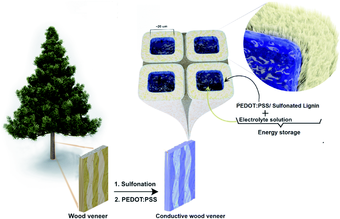 | ||
| Fig. 1 Schematic illustration of the conductive wood veneer preparation. | ||
PEDOT:PSS is one of the most widely used ionic/electric conducting polymers. PEDOT:PSS has shown a conductivity of up to 4380 S cm−1 and has been studied as electrode materials in supercapacitors, as the active channel in electrochemical transistors, and as the active leg in thermoelectric devices.5,16–18 To utilize the excellent electrical, mechanical, and processability properties of PEDOT:PSS, it has been explored as a conductive component in 3D structured composites such as cellulose-based aerogels,19 graphene aerogels,20 electronic textiles,21 and bone-tissue scaffolds.22 Typically, PEDOT:PSS has also been used for electrically conductive paper structures utilized as a supercapacitor electrode.5 Such electrodes can be combined with redox-active lignosulfonate for improved supercapacitor storage capacity.5 This is promoted by an important detail, namely the ability of PEDOT to be doped not only by its common counter ion PSS− but also by sulfonated lignin.5,6
In the first stage of the present approach, some of the lignin and hemicellulose components are removed to increase specific surface area and create small-scale porosity for the electrolyte. The lignin is also sulfonated. Then PEDOT:PSS is introduced into the modified wood structure. The polymer not only makes the wood conductive but also provides strong electrostatic interaction with the sulfonated lignin component, promoting intimate coupling between the redox-active lignin and the charge-transporting PEDOT. This coupling is of critical importance in order to achieve the desired pseudo-capacitance performance in energy storage applications.5,6 Here, we will investigate how the sulfonation treatment time influences the composition of the resulting wood template and how that, in turn, affects the following PEDOT:PSS impregnation. Morphological, as well as electrical characteristics, will be studied and analyzed, with special emphasis on the interplay between PEDOT and lignin and the pseudocapacitive behavior that should result. This will help to clarify mechanisms and consider approaches for optimized wood nanocomposite structures. We also provide proof of concepts showing the possibility to utilize wood as an electrode for both electrical conductivity and pseudocapacitive energy storage, with potential for further development. To strengthen the last point, an asymmetric wood supercapacitor prototype was fabricated and characterized.
2. Experimental
2.1. Materials
Natural pine veneers were obtained from Glimakra of Sweden AB. Poly(3,4-ethylenedioxythiophene)–poly(styrenesulfonate) (PEDOT:PSS, CLEVIOS™ PH 1000) was purchased from Heraeus Deutschland GmbH & Co. KG, Germany. Sodium sulfite anhydrous (Na2SO3, Fisher Scientific), sulfuric acid (H2SO4, >95%, Fisher Scientific), acetone (≥99.5%, VWR), dimethyl sulfoxide (DMSO, Sigma Aldrich), and ethanol (Sigma Aldrich) were all used as received. Carbon felt was purchased from SGL Carbon, while Carbon fibers, paraffin wax, and carbon paste were received from Sigma Aldrich and used as received.2.2. Wood veneer (WV) sulfonation
Wood veneers (WVs) were cut into a size of 3.0 × 1.0 × 0.075 cm3 (longitudinal × tangential × radial) and immersed in deionized water under vacuum prior to chemical modification. The wet WVs (7 pine veneers of roughly 700 mg of dry weight) were sealed in an acid digestion vessel containing 16 ml of a Na2SO3 solution (0.7 M) at pH 7 adjusted with the addition of H2SO4 at room temperature. The vessel was then transferred to a silicone oil bath preheated at 80 °C and kept for 1 h. After this impregnation step, the temperature of the oil bath was increased to 165 °C and kept for different reaction times: 30 min, 1 h, 3 h, and 5 h. Accordingly, the resulting modified WV products were labeled as SWV-0.5, SWV-1, SWV-3, and SWV-5, respectively. At the end of the reaction, the vessel was rapidly quenched in an ice water bath, and the modified SWVs were thoroughly washed 3 times with acetone and subsequently 3 times with deionized water under vacuum.2.3. Conductive wood veneers (CWVs) preparation
The CWVs were obtained by impregnating SWVs into a suspension of PEDOT:PSS and DMSO, followed by a drying process. The suspension was prepared by mixing 6.0 g of DMSO with 100 g of PH1000, in which the mass ratio of PEDOT:PSS and DMSO are about 1![[thin space (1/6-em)]](https://www.rsc.org/images/entities/char_2009.gif) :5, respectively. To prepare the CWVs, two SWV samples were soaked completely into a 25 ml Petri-dish containing 16.0 (g) of the suspension. The disk, after that, was placed directly in an air-drying oven at 75 °C and kept for 10 hours until the samples are dried. The final CWV products were achieved after completely removing the aggregated polymer layers on the surface of the dried samples (Fig. SI.12, ESI†).
:5, respectively. To prepare the CWVs, two SWV samples were soaked completely into a 25 ml Petri-dish containing 16.0 (g) of the suspension. The disk, after that, was placed directly in an air-drying oven at 75 °C and kept for 10 hours until the samples are dried. The final CWV products were achieved after completely removing the aggregated polymer layers on the surface of the dried samples (Fig. SI.12, ESI†).
2.4. Characterizations
The characterizations are presented in detail in the ESI.†3. Results and discussion
The synthetic route to obtain the conductive wood veneer has two main steps. In the first step, wood veneer (WV) was treated in a sodium sulfite solution (0.7 M) at 165 °C. The pH of the solution was adjusted to 7 with the addition of a sulfuric acid solution. The samples were treated for different reaction times with the purpose to study the effect of reaction time on the WV structure and the impact on its chemical composition. Our goal was to obtain a modified WV electrode with a well-preserved wood structure, which at the same time possesses a sufficient amount of sulfonated lignin. The obtained sulfonated wood veneers (SWVs) were labeled as SWV-1/2h, SWV-1h, SWV-3h, and SWV-5h following the reaction time of 1/2 h, 1 h, 3 h, and 5 h, respectively. In the second step, the SWVs were impregnated with PEDOT:PSS suspension in dimethyl sulfoxide and completely dried in an oven at 75 °C to produce the final conductive wood veneer (CWVs) electrodes. The CWVs samples were correspondingly labeled as CWV-1/2h, CWV-1h, CWV-3h, and CWV-5h, respectively.3.1. Structure and morphology of sulfonated wood veneers (SWVs)
The sulfite pulping process is one of the most common techniques in the paper industry, and the chemistry of the process was extensively studied in the literature.23 In the process of delignification, hydrophilic sulfonic acid groups are generated in the hydrophobic lignin polymer via sulfonation at the same time as the molecular weight of lignin is lowered via hydrolysis of ether bonds between the phenylpropane units.23 To preserve the sulfonated lignin in the native wood structure, the hydrolysis reactions should be slow compared to sulfonation. This is achieved by providing sodium sulfite treatment at neutral pH and the heterogeneous reaction within the intact wood veneer. The amount of total acidic groups in the SWV samples was quantified by conductometric titration according to SCAN-CM 65:02. The weak acid groups (carboxylic acid groups) are attributed to the uronic acid residues in native wood,24 while the strong acid groups correspond to the sulfonic acid groups generated by sulfonation. As shown in Fig. 2a, the content of weak acid groups increased from 87 to 137 μmol g−1 after ½ h sulfonation, and thereafter remained more or less constant despite longer treatment times. However, the sulfonic acid groups increased significantly from 9 to 300 μmol g−1 after 30 minutes of sulfonation reaction, then increased gradually up to 375 μmol g−1 for the longest reaction time of 5 h. The progressive solubilization of sulfonated lignin with increasing reaction time was monitored by UV-vis spectroscopy (Fig. SI.4a, ESI†). The concentration of sulfonated lignin in the spent reaction solution was quantified by the absorbance at 280 nm using an extinction coefficient (ε) of 11.9 l g−1 cm−1 after background correction.25 The concentration of soluble sulfonated lignin increased linearly from 0 to 1 h reaction time and then increased gradually, but slower, with a longer reaction time (Fig. SI.4b, ESI†), leading to deep yellow solutions. Due to the dissolution of hemicellulose and noncellulose components, a large number of micro- and nanopores were created in the sulfonated wood structure, making it increasingly porous and thus resulting in a higher surface area. Indeed, the results of BET measurements revealed a significant enhancement of surface area from WV-native to SWV-5h. In Fig. 2b, WV-native has a surface area of 0.14 m2 g−1, which is negligible in comparison to 25.75 m2 g−1 of SWV-1h and especially to 176.87 m2 g−1 of SWV-5h. With higher surface areas, the SWVs are believed to have a larger capacity for the infiltration process of PEDOT:PSS, resulting in higher charge storage capacity in the resulting conductive veneers.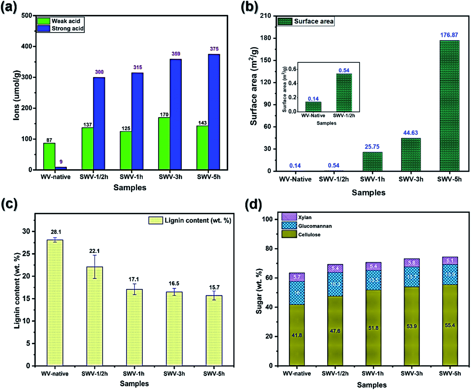 | ||
| Fig. 2 The effect of reaction time on the chemical composition of sulfonated wood veneers (SWVs). (a) The content of sulfonic acidic groups and carboxylic acid groups in the WV-native and SWV samples as measured by conductometric titration. (b) The surface area of WV-native and SWV samples. (c) Lignin content in the WV-Native and SWV samples as determined based on gravimetric Klason lignin. (d) The content of cellulose, xylan, and glucomannan in the WV-native and SWV samples. | ||
The Klason lignin content of the WV and SWV samples (Fig. 2c) was measured gravimetrically after acid hydrolysis, while the cellulose and hemicellulose contents (Fig. 2d) were determined by sugar analysis of acid hydrolyzed monosaccharides. The chemical compositions including cellulose, glucomannan, xylan, and lignin of the WV and SWV samples are summarized in Tables SI.1 and SI.2, in the ESI.† The lignin content decreased significantly during the initial phase (1 h) of the sulfonation progress at neutral pH and thereafter decreased more slowly. More than half of the lignin was retained in the SWVs (15.7 wt% at 5 h) as compared to native WV with a lignin content of 28 wt%. The removal of hemicelluloses (mostly glucomannans) was slow during the initial phase (1/2 h), then gradually increased as more lignin was removed after 1 h. This indicates the selectivity of delignification in accordance with previous studies on neutral sulfite pulping as compared with acid sulfite and kraft pulping.23 The cellulose content in the SWVs increased gradually with the increasing sulfonation time due to the partial removal of lignin and hemicelluloses.
Fig. 3 shows the SEM micrographs for the cross-sections of the SWVs prepared with varying sulfonation times. The sulfonation of lignin occurred in specific regions of the wood structure, leading to a progressive erosion of lignin mainly from middle lamella and cell wall corners.25 The dissolution of lignosulfonates started in the latewood region and proceeded to the earlywood region. After a 5 h reaction, the middle lamella and cell wall corners were completely eroded throughout the sample (Fig. 3e). This resulted in a progressive softening of the WV, which was observed when handling the samples. In addition, we could observe a gradual smoothening of the borders between earlywood and latewood (Fig. 3f). The original hierarchical structure of the WV stayed intact, with slightly deformed cell walls starting after 1 h of reaction time. Nonetheless, the opening of the cell wall corner and middle lamella and the presence of charged sulfonic groups favor the swelling of the wood cell walls,26 which allows for a better (in)flow of the conducting PEDOT:PSS polymer inside the wood structure during impregnation.
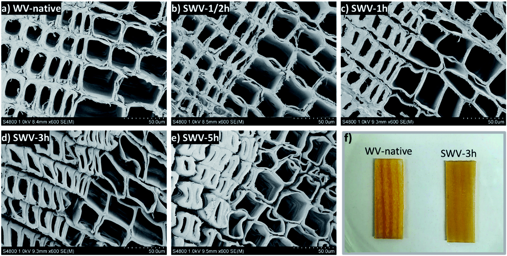 | ||
| Fig. 3 Effect of sodium sulfite treatment under neutral pH at 165 °C on the wood structure of SWVs. SEM micrographs showing cross sections of the sulfonated WVs prepared by different reaction times, (a) native wood, (b) 1/2 h, (c) 1 h, (d) 3 h, (e) 5 h, and (f) photographs of the wet veneers before and after sulfonation. | ||
3.2. Structure and morphology of conductive wood veneers (CWVs)
Following sulfonation, the conductive PEDOT:PSS polymer was successfully infiltrated into the SWVs. Instead of the SWV yellow color, the CWVs appear optically dark-blue, which indicates a substantial contribution from PEDOT:PSS. When comparing CWVs treated for different sulfonation times, we note that CWV-native has a lighter color than the others, indicating a relatively lower total mass loading of PEDOT:PSS into the wood structure. The mass loading of PEDOT:PSS into the different CWVs was measured by simply weighing the samples and the results are presented in Table SI.3 (ESI†) together with sample thickness. Since CWVs have different thicknesses, the PEDOT:PSS contents were calculated with respect to the sample area rather than the sample volume. In this way, the numbers will reflect the different loading capacities of PEDOT:PSS for the native WV and the SWVs. The PEDOT:PSS mass loading for the native WV reaches about 2.6 ± 0.2 mg cm−2. For the SWV samples, the level of loading increases to 4.0 ± 0.2 mg cm−2 as the sulfonation time increases to 1 h. Further increase of the reaction time to 5 h only results in a slight increase of the mass loading to finally reach 4.5 ± 0.5 mg cm−2.The microstructure of the oven-dried CWV-native and CWV-1h samples was characterized by optical microscopy and SEM. In the native WV (Fig. 4a), PEDOT:PSS remains mostly on the outer surface and penetrates inside the veneer only in some sporadic spots. On the contrary, a homogeneous diffusion of the conductive polymer throughout the thickness of the SWV-1h sample was observed (Fig. 4b). The samples were wetted, cut with a microtome, air-dried, and imaged with SEM. As shown in Fig. 4f, the wood micro-structure was preserved after impregnation and the cell lumens were empty and available for the electrolyte to flow inside the lumen channels. A PEDOT:PSS coating layer is believed to be formed on the interior lumen surface, probably in the few hundred-nanometer range, which is too thin to be identified from the cross-section image (Fig. 4f) but was observed from the longitudinal cut (Fig. 4d) as a very fine wrinkly layer covering the pits. This coating layer was present only in the CWV-1h sample and not in the CWV-native one, as the PEDOT:PSS polymer could not penetrate inside the native WV (Fig. 4a).
 | ||
| Fig. 4 Microstructure of the air-dried CWVs. Photographs of (a) native wood veneer and (b) SWV-1h after PEDOT:PSS infiltration and oven drying at 75 °C. SEM micrographs of the longitudinal section (c and d) and cross-section (e and f) of the two samples CWV-native and CWV-1h. The samples were rewetted, cut with a microtome, and air-dried before imaging. | ||
To further study the distribution of PEDOT:PSS inside the WV, the CWV-1h and CWV-native samples were either air dried or supercritical-dried by liquid CO2 (CPD) after the solvent exchange with ethanol. When the samples were air-dried after ethanol exchange, delamination of the wood cell walls along the middle lamella was observed for the CWV-1h sample (Fig. 5e). In contrast, the samples dried in the air after rewetting in water (Fig. 4f) did not show such delamination. After supercritical drying using CO2, a clear peeling off of the PEDOT:PSS polymer could be observed, both in the cross-section (Fig. 5f) and along the longitudinal section (Fig. 5g) of the CWV-1h sample, but not in the CWV-native sample (Fig. 5b, c), due to the fact that liquid CO2 partially solubilizes the polymer.27 The polymer was found either as peeling-off layers along the cell wall surfaces or appeared as wrapped-up layers inside the lumen. At an even higher magnification of images recorded along the longitudinal section, the S3 layer (the innermost part of the secondary wall) with oriented cellulose microfibrils was observed in the lumen cell wall surface of the CWV-native sample, which indicates no infiltration of the PEDOT:PSS (Fig. 5d), while a web-like nano-structure of PEDOT:PSS polymer was found in the CWV-1h sample (Fig. 5h and j). The resulting morphology is clear from Fig. 5i where a representative lumen shows a continuous PEDOT:PSS layer peeled after CPD drying. Similar morphology was also found for the PEDOT:PSS aerogel prepared from supercritical CO2 drying.27 The observed morphology of PEDOT:PSS in wood is truly unique compared to the reported morphology of conductive materials-modified wood structure (see Table SI.5, ESI†). A further study on the polymer layer thickness on the cell lumen surface was carried out using an image analysis method and is presented in Fig. SI.5, in the ESI.†
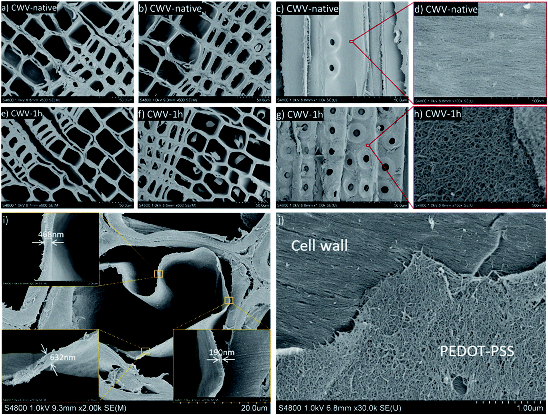 | ||
| Fig. 5 Microstructure of the CWVs prepared by supercritical drying. SEM images of the cross-section of (a) CWV-native and (e) CWV-1h samples that were air-dried after solvent exchange from water to EtOH. SEM images of the cross-section and longitudinal section of (b and c) CWV-native and (f and g) CWV-1h samples prepared by supercritical drying using liquid CO2. SEM images of higher magnification for longitudinal section showing the oriented cellulose fibril network structure of the S3 layer of the secondary wood cell wall for (d) CWV-native sample and the PEDOT:PSS polymer network structure for the (h) CWV-1h sample after supercritical drying. (i) Representative lumen showing a peeled-off polymer layer by CPD drying. The width of the PEDOT:PSS layer was measured in three different regions. (j) SEM micrograph at high magnification of the longitudinal section of WVC-1h sample, highlighting the web-like PEDOT:PSS layer (bottom) on top of the aligned fibers in the S3 layer of the cell wall. | ||
From the microstructure analysis, we can confirm that the conductive polymer forms a continuous phase on the internal surface of the cell lumen channels, which ultimately should guarantee good conductive and capacitive performance while explored as electrodes in devices. Sulfonated lignin carries a negative charge and is expected to serve as a counterion for the positively doped PEDOT moieties.5,6
3.3. Electrical and electrochemical properties of CWV wood electrodes
The CWVs obtained after PEDOT:PSS infiltration present different electrical conductivity values, depending on the degree of sulfonation. In Fig. 6a, the conductivity of CWVs increases from 29 S m−1, for CWV-native to 203 S m−1, for the CWV-5h sample, indicating the role of the sulfonation process in facilitating the PEDOT:PSS infiltrating process, and creating the electrostatic interaction between doped PEDOT and sulfonated lignin. The interaction plays most likely an important role in the increase of the conductivity recorded from the different CWVs.6 Interestingly, there is very little difference in the conductivity measured on samples treated for 1 h and 3 h, whereas the 5h-sample again shows a significant increase and reaches 203 S m−1. However, the PEDOT:PSS mass loading only increases from 4.0 to 4.4 mg cm−2 while comparing the 1h- and 5h-samples. This indicates that the conductivity increase is probably connected to the smaller sheet thickness of CWV-5h (580 μm, compared to 690 μm for the CVW-1h sample). With a longer sulfonation time, the wood structure becomes softer and thereby more easily compressed during the drying process that follows the polymer infiltration. This also explains why the trend for the sheet resistance is different from the trend in conductivity since the former changes with thickness while the latter does not. Besides that, the conductivity values here obtained are significantly higher than previously reported values from conductive woods induced by polypyrrole (39 S m−1 (ref. 12)) or polyaniline (0.9 S m−1 (ref. 28) 0.01 S m−1 (ref. 29)). In fact, our CWV-5h sample has a value competitive with the conductivity of a wood–PEDOT:PSS aerogel (217.3 S m−1 (ref. 30)), which is measured using a different technique. The high conductivity of CWVs is related to the effects of the sulfonation process, but also to the use of a secondary dopant (DMSO), which is known to boost the conductivity of PEDOT:PSS according to the supplier of up to 850 S m−1. This suggests that PEDOT:PSS is a useful and versatile materials system transforming wood into a conductive bulk.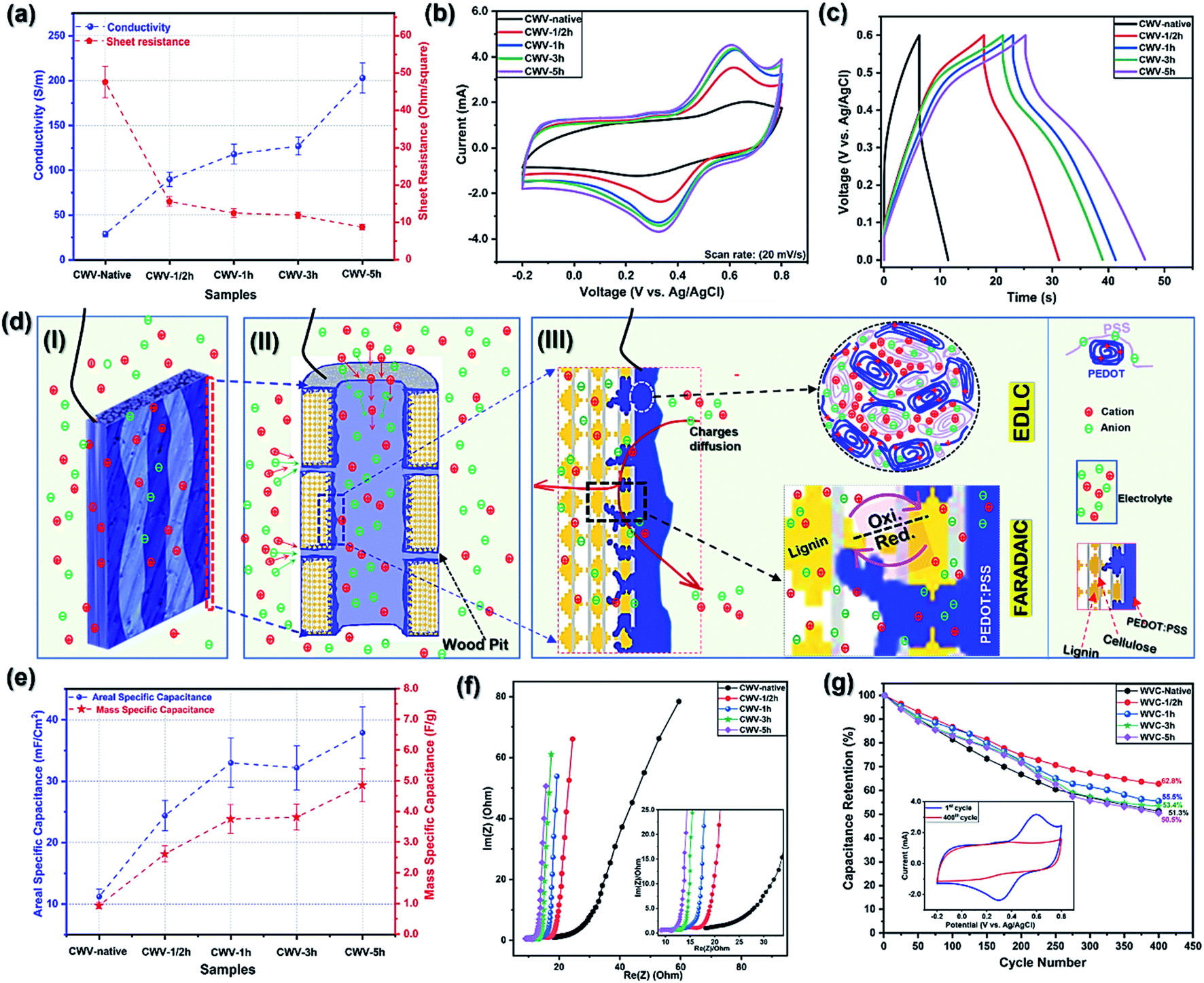 | ||
| Fig. 6 (a) The conductivity and sheet resistance of CWVs; (b) CV curves of CWVs at the same scan rate of 20 mV s−1; (c) charge/discharge curves of CWVs at the same current density of 1.0 mA cm−2; (d) the electrochemical operation of (I) a single CWV electrode, (II) the CWV channels, (III) a section of a single CWV channel, and the interface of CWV cell-wall channel; (e) the specific mass- and area-capacitance of CWVs at the same current density of 1.0 mA cm−2; (f) Nyquist plot of WVCs at the same frequency range of 50 mHz to 100 kHz (inset: Nyquist plot of WVCs at the high frequency); (g) capacitance retention of WVCs after 400 CV cycles (inset: CV curves of WVC-1h at the 1st and 400th cycle at the same scan rate of 20 mV s−1). | ||
Along with conductivity characterizations, the electrochemical properties of all the CWV samples were investigated. This was achieved by contacting the CWV electrodes (2.5 × 1.0 cm2) immersed into a 1 M NaCl electrolyte and performing a three-electrode characterization, see Fig. SI.2, in the ESI.†
CV curves of the CWV electrodes recorded at a scan rate of 20 mV s−1 are shown in Fig. 6b. The smallest area under the current–voltage curve is found for the CWV-native sample and the area increases for the sulfonated samples, suggesting that the sulfonation process is producing a higher charge-storage capacity of the CWV electrode. In the potential window of 0.3 V to 0.8 V, all CV curves present a pair of archetypical faradaic-redox reaction peaks, which correspond to the oxidized/reduced states of quinone rings in lignin.5,6 This is important and indicates that lignin not only intimately interacts with PEDOT but also contributes significantly to a pseudo-capacitive behavior of the resulting CWV electrodes.5,6 Interestingly, the broadest and highest intensity peaks are seen in the CV curve of the longer sulfonation time sample, suggesting that a higher amount of lignin is utilized for charge storage. As the sulfonation time increases, the SWVs become more porous and have a larger surface area, which could facilitate better PEDOT access to lignin in the interior parts of the wood structure. The better access of PEDOT to lignin, the higher amount of lignin is utilized. In the lowest potential range (−0.2 V to 0.2 V), a slight increase in the area and a more box-like behavior are found for the CV curves, as the level of sulfonation is increased. This increase includes both a small shift of the capacitance and also a reduction in resistance. As the level of sulfonation increases both a greater loading of PEDOT and a different ionic environment, due to the combination of PSS− and sulfonated lignin,6 is achieved.
In Fig. 6d, we present an interpretation of the capacitance utilization mechanism of sulfonated lignin and PEDOT:PSS in the CWV supercapacitor electrodes. In Fig. 6d(I) and (II), a single CWV electrode and a section of one of its single cell-wall channels are illustrated. The interior of the channel is coated with PEDOT:PSS as deduced from the SEM images (Fig. 5). In Fig. 6d(II) and (III), we illustrate the proposed mechanism for ionic charge transport: we speculate that the electrolyte charges can diffuse and penetrate throughout the wood structure through the central lumen of the wood cell-wall, or by passing through the wood pits, the micro-and nanopores that were created during the sulfonation process as suggested by the BET data (Fig. 2b). During charging, the electrolyte charges are absorbed inside the PEDOT:PSS matrix, facilitating the formation of a Helmholtz/electrical double-layer at the interface between PEDOT-rich and PSS-rich interconnected grains.31 Simultaneously, during the charge/discharge process, the faradaic redox reactions of lignin are governed by the charges (e−/H+) transferred at the interface between the PEDOT backbone and the lignin quinone rings.5,6 These two charge storage processes (EDLC and faradaic) occur simultaneously to produce the total pseudo-capacitance of the CWV electrodes.
Based on the trends of the areas of the CV curves, we found that CWV-1h and CWV-5h have the highest specific capacitance values, which also agrees with their galvanostatic charge–discharge (GCD) curves presented in Fig. 6c where CWV-1h and CWV-5h have the longest discharge times, recorded at a given current density of 1 mA cm−2. The areal and mass-specific capacitances were calculated using the data in Fig. 6c and are presented in Fig. 6e, showing an increased value while comparing the samples from the CWV-native to the CWV-5h sample. Overall, the areal-specific capacitance increases from 11 mF cm−2, of the CWV-native sample, to 38 mF cm−2, of the CWV-5h, with the largest relative increase occurring native up to a 1 h treatment time. We interpret this as an indication of the critically important impact of the sulfonation process, both with respect to opening up the wood structure for the conducting polymer infiltration but also by introducing sulfonic groups to create electrostatic interactions with the conducting polymer. The mass of active materials (lignin and PEDOT:PSS) is measured and presented in table SI.3,† where a 2.5 cm2 electrode of CWV-5h has an active mass of ≈20.0 mg. Accordingly, CWV-5h has a normalized mass-specific capacitance of 4.9 F g−1 at a current density of 1 mA cm−2. The obtained value is smaller than reported values for lignin/PEDOT:PSS composites (230 F g−15,6), which is to be expected since, with our current approach, only a part of the lignin in the wood structure is accessed by PEDOT. The capacitance is also smaller than some other reported wood-based supercapacitor electrodes (Table SI.†5, ESI†); the main reason being that those studies rely on either carbonized wood-based electrodes or electrodes modified with a high mass volume of conducting polymers such as PANI and PPy. In this work, we aim first and foremost to develop a new approach that proves the concept of native lignin utilization; thus, the wood could not be carbonized since this would destroy the lignin component. We also do not seek in this study to maximize the mass loading of conductive polymer (Fig. SI.12, ESI†); rather, the focus is to demonstrate and verify the coupling between conductive polymer and lignin. Consequently, the capacitance is lower than the values referred to above but clearly indicates that our proposed approach is applicable. As shown in Table SI.5,† the concept of utilizing native lignin's capacitance and the 3D structure of native wood is truly unique. For increasing the electrode capacity, we propose either to introduce a higher mass volume of active materials into the wood or to improve the access of the conducting polymer to lignin inside the wood nanostructure. Possible ways of doing this include vacuum infiltration, or in situ polymerization of a high volume of monomer molecules that have been allowed to penetrate throughout the wood structure before being polymerized.
In addition to the capacitance values, when incorporating the CWV electrodes in a supercapacitor, other characteristics are of critical importance, such as charge transfer, ion transport/diffusion, and cycling stability. In Fig. 6f, we present the Nyquist plots of the CWVs, which have vertical lines and elongated semicircles at low and high frequencies, respectively. The elongated semicircle indicates that several processes may be involved in the EIS measurement in the high-frequency range.32 From the high-frequency region, see the inset of Fig. 6f, the equivalent series resistance (ESR) is found by intercepting the Re(Z) axis with the Nyquist plots showing a span from 18.1 Ω in WVC-native to 9.0 Ω in WVC-5h sample. In addition, CWV-1h and CWV-3h have nearly the same ESR values of 10.6 Ω and 10.5 Ω, respectively, which is slightly lower than that of WVC-1/2h (11.8 Ω). The charge transfer resistance (Rct) of the CWVs can be evaluated by the diameter of the semicircle from the same plots, which gives corresponding values ranging from 4.5 Ω for CWV-1/2h down to 2.2 Ω for CWV-5h (Table SI.4, ESI†).32–37 The lower ESR value indicates a lower electrode and electrode-collector contact resistance, while the lower Rct suggests a faster charge transfer at the interface of the electrode–electrolyte.33,34,36,37 Besides that, in the low-frequency region, the straight lines of Nyquist plots are recoded, suggesting the slow ions-diffusion, and capacitive behavior of the CWV electrodes.33,36,37
Repeated cycling was carried out, with data are shown in Fig. 6g that reveals a reduction in capacitance by 40–50% after 400 cycles. We attribute this to the disconnection/disintegration of included active materials, the dissolution of sulfonated lignin into the electrolyte, and the discontinuation of the electrostatic interaction between sulfonated lignin and doped PEDOT5 (see Fig. SI.6 and SI.7, ESI†). In general, the capacitance retention values show higher capacitance loss for the longer sulfonation time CWV samples. This is related to the higher amount of lignin, in relation to the total lignin content but also in absolute numbers, as is seen in Fig. 6b, which was utilized for storing charges. As seen in the inset of Fig. 6g, practically all the lignin-based capacitance is lost after cycling. Since the long-reaction-time materials have a relatively larger lignin-based contribution to the capacitance, these materials will, relatively, lose more of their capacitance in the cyclic stability test. During the test, the dissolution of sulfonated lignin is caused by its strong hydrophilic characteristics and the electrostatic repulsion, induced by PSS− counter ions. This issue has been studied and solved in our previous work by introducing sulfonated lignin into the aqueous electrolyte.5 Below, we show that the consumed reaction solution of the sulfonation process can be re-used as a supercapacitor electrolyte since it carries the solvated sulfonated lignin released from the wood samples.
Looking from the aspect of saving energy, the conductivity and electrochemical results suggest that 1 h and CWV-1h are the optimal reaction time and the most applicable electrode template. Therefore, CWV-1h was further used and explored to derive an asymmetric supercapacitor prototype device.
3.4. Wood-based electrolyte
The spent reaction solution (RS) is a side-product of the sulfonation process, but, in this study, this residual solution was also studied as a potential electrolyte for wood-based supercapacitors. The primary reason for attempting this idea is the sulfonated lignin content of the RS, which we expect to counter the dissolution of lignin from the CWV during charge–discharge cycling. Especially, by using RS as an electrolyte in the same setup as used in the CWVs electrode measurements, the CWV-1h electrode shows capacitance retention of 88.2% after 400 cycles and 77.3% after 1000 cycles, which significantly surpasses the 55.5% retention found after 400 cycles by using a NaCl (1 M) electrolyte (cf.Fig. 6g). This improvement is attributed to the RS chemical components, which include wood extractives, hemicellulose, sulfonated-lignin, and sodium sulfite derivatives. We see this as an indication that waste products, like the RS, are proven to be eco-friendly, and useful as an economic alternative to other electrolytes. However, there is also a decrease in the measured capacitance while applying this RS approach; full details are presented in the ESI and Fig. SI.8.†3.5. CWV asymmetric wood supercapacitor (CWV-AS)
The CWV-1h electrode, selected as described above, was used to fabricate an asymmetric supercapacitor, which was mechanically stable before and after the measurement. This is because the native wood 3D structure is well preserved in the obtained CWVs, making CWVs mechanically robust and easy to handle (the mechanical testing results presented in Fig. SI.9 and SI.10, ESI†). A sketch of the device is shown in the inset of Fig. 7a, in which CWV-1h and PEDOT:PSS-coated carbon felt (C-PP, in size of 2.5 × 1.0 cm2) are the two electrodes, while the device separator is a cellulose-polyethylene(PE) tissue membrane. The thickness of CWV-1h and C-PP electrodes are 690 μm and ≈2.4 mm, respectively, so the device's thickness is ≈3.3 mm in total. In this device, NaCl 1 M was applied as the electrolyte so that a fair comparison could be made between the device and its corresponding electrode properties. The supercapacitor is characterized as a two-electrode system. | ||
| Fig. 7 (a) The CV curves of WVC-1h and C-PP at the same scan rate of 20 mV s−1 (inset: the structure of a CWV-AS); (b) CV curves of CWV-AS at different scan rates from 10 to 50 mV s−1; (c) the charge/discharge curves of the CWV-AS at different current densities; (d) Nyquist plot of the CWV-AS at the frequency range of 50 mHz to 100 kHz (inset: the Nyquist plot at the high frequency); (e) (inset: CV curves of CWS-AS at the different cycle numbers); (f) the power and energy densities of CWV-AS (inset: the prototype CWV-AS). | ||
In Fig. 7a, the nearly rectangular shape of the C-PP's CV curve identifies it as a nearly ideal electrode for an EDLC supercapacitor, while WVC-1h has the archetypical characteristic redox peaks and therefore is suitable as one electrode in an asymmetric device.38 Accordingly, the CV curves of the full device shown in Fig. 7b, are a combination of the characteristics of the two individual electrodes. The CV curves have a similar shape for all scan rates between 10 and 50 mV s−1, indicating the good reversibility for the redox reactions and rate capability of the resulting device.39,40
We note that due to the different working potential windows of C-PP and CWV-1h, the asymmetric supercapacitor's combined working potential can be increased to 1.2 V instead of 1.0 V in the single electrodes. In Fig. 7c, the device GCD curves are presented, showing a behavior consistent with the CV curves. At higher current density, the charge and discharge times are lower, but all discharge curves have the same general shape indicating a mix of EDLC and faradaic contributions. Based on the discharge times, the device's areal capacitances are 22.9, 22.3, 21.7, and 21.1 mA cm−2 at the current densities of 1.2, 1.6, 2.0, and 2.4 mA cm−2, respectively. The corresponding capacitances per unit weight at the same current densities are 356, 350, 343, and 335 mF g−1.
The Nyquist plot in Fig. 7d shows the good characteristics of a supercapacitor with the presence of a near semicircle curve at the high frequencies, which is followed by a steep evolution at lower frequencies. Similar to the discussion in Fig. 6f, the elongated semicircle is probably a result of different charge transport processes occurring in the two electrodes of the device. From the Nyquist plot, the evaluated ESR of the device is 6.0 Ω, indicating rather low electrode and electrode/contact resistances.32–34,36
Together with the potential capacitance and low ESR, the device capacitance is retained at 73.4% and 72.1% after 400 and 500 stability cycles, respectively, which again exceeds the capacitance retention of its electrode (CWV-1h). In the inset of Fig. 7e, after 500 stability cycles, the redox reaction peaks found in the CV curve have completely disappeared, indicating that the capacitance reduction is mainly attributed to the loss of redox components (sulfonated-lignin) in the CWV-1h electrode. This property also corresponds to the cyclic stability of CWV-1h measured in the three-electrode system. Besides that, in the potential range of −0.2 V to 0.3 V, there is a small current reduction between the first and the 500th cycle CV curves, which is attributed to the loss of PEDOT:PSS capacitance. As shown in the Ragone plot in Fig. 7f, we calculate the device's energy density for different current densities (1.2 to 2.4 mA cm−2) to 74.9, 73.0, 71.1, and 69.2 mW h kg−1, while the corresponding power densities are 12.6, 17.0, 21.5, and 26.3 W kg−1, respectively. The energy density values are far from the reported values of wood-carbon supercapacitors due to the high fraction of non-conductive materials in the WVC-1h electrode. However, this study aims to demonstrate the possibility to utilize wood as a lignin donor template for supercapacitor electrodes.
3.6. Wood supercapacitor
The carbonized wood-based supercapacitor has been widely studied,2,3,8,30,41 whereas the wood supercapacitor (WS) has not, due to the lack of an efficient method to transform wood into a high-performing wood electrode. In this study, for the first time to our knowledge, a prototype WS was constructed where both the electrodes and the separator are based on true wood structures. The two electrodes are PEDOT:PSS-coated delignified wood (DWV-PP, 490 μm thick) and CWV-1h (690 μm thick), while the device separator is tailor-made from SWV-1h with a thickness of 140 μm. The device's thickness is ≈1.3 mm in total. At a current density of 1.2 mA cm−2, the device has an areal capacitance of 19.0 mF cm−2, while having a low ESR of 6.4 Ω, indicating a good supercapacitor behavior. The details are presented and discussed in the ESI and Fig. SI.11.† This primary achievement suggests a new approach for the researcher to develop biodegradable supercapacitors based on wood in the future.4. Conclusion
In this work, a simple and green synthetic method was developed to transform wood directly into a micro-and nanostructural tailored conductive wood template which, for example, is applicable for energy storage devices. Native lignin was successfully functionalized by introducing more than 300 μmol of sulfonic groups to each gram of wood, while the lignin content remained higher than 16 wt%. The CWVs not only have a well-preserved 3D wood structure but also a homogeneous distribution of PEDOT:PSS inside the wood structure, coating the inner surface of wood fiber channels. This materials design is tailored to provide efficiency in terms of a high ratio between performance and PEDOT:PSS content. The CWV (CWV-1h sample) shows a conductivity of 118 S m−1, which at the comparably low polymer content is very promising for wood-based electronics applications. Furthermore, the preserved but functionalized lignin component was utilized to boost the capacitance of the electrode up to three times higher than that of the untreated sample, which was shown in an asymmetric supercapacitor. The synthetic method and the materials design of the conductive wood template represent a new approach, which can underpin materials development for further applications in energy storage devices and other electronic components.Conflicts of interest
The authors declare no competing interests.Acknowledgements
This work was financially supported by the Wallenberg Wood Science Center (Knut and Alice Wallenberg Foundation) and the Karl-Erik Önnesjö Foundation. We also acknowledge the support from Treesearch, a collaboration platform for Swedish forest industrial research. We gratefully acknowledge the assistance of Martin Lawoko and Martin Höglund in the preparation of the sulfonated wood samples. We wish to thank Mikhail Vagin, Jesper Edberg for the insightful discussion, Mehmet Girayhan Say for the assistance in the SEM measurement, and Jonas Garemark for his help with the paper scheme preparation.References
- C. Chen, Y. Kuang, S. Zhu, I. Burgert, T. Keplinger, A. Gong, T. Li, L. Berglund, S. J. Eichhorn and L. Hu, Nat. Rev. Mater., 2020, 5, 642–666 CrossRef CAS.
- H. Zhu, W. Luo, P. N. Ciesielski, Z. Fang, J. Y. Zhu, G. Henriksson, M. E. Himmel and L. Hu, Chem. Rev., 2016, 16, 9305–9374 CrossRef PubMed.
- J. Huang, B. Zhao, T. Liu, J. Mou, Z. Jiang, J. Liu, H. Li and M. Liu, Adv. Funct. Mater., 2019, 29, 1902255–1902277 CrossRef.
- Z. Wang, Y.-H. Lee, S.-W. Kim, J.-Y. Seo, S.-Y. Lee and L. Nyholm, Adv. Mater., 2021, 33, 2000892–2000909 CrossRef CAS PubMed.
- J. Edberg, O. Inganäs, I. Engquist and M. Berggren, J. Mater. Chem. A, 2018, 6, 145–152 RSC.
- F. N. Ajjan, N. Casado, T. Rębiś, A. Elfwing, N. Solin, D. Mecerreyes and O. Inganäs, J. Mater. Chem. A, 2016, 4, 1838–1847 RSC.
- O. Nechyporchuk, N. B. Belgacem and J. Bras, Ind. Crops Prod., 2016, 93, 2–25 CrossRef CAS.
- C. Chen, Y. Zhang, Y. Li, J. Dai, J. Song, Y. Yao, Y. Gong, I. Kierzewski, J. Xie and L. Hu, Energy Environ. Sci., 2017, 10, 538–545 RSC.
- L. L. Lu, Y. Y. Lu, Z. J. Xiao, T. W. Zhang, F. Zhou, T. Ma, Y. Ni, H. B. Yao, S. H. Yu and Y. Cui, Adv. Mater., 2018, 30, 1706745–1706753 CrossRef PubMed.
- S. Lyu, Y. Chen, S. Han, L. Guo, N. Yanga and S. Wang, RSC Adv., 2017, 7, 54806–54812 RSC.
- S. Lv, F. Fu, S. Wang, J. Huang and L. Hu, RSC Adv., 2015, 5, 2813–2818 RSC.
- W. Gan, C. Chen, M. Giroux, G. Zhong, M. M. Goyal, Y. Wang, W. Ping, J. Song, S. Xu, S. He, M. Jiao, C. Wang and L. Hu, Chem. Mater., 2020, 32, 5280–5289 CrossRef CAS.
- C. Xiong, M. Li, S. Nie, W. Dang, W. Zhao, L. Dai and Y. Ni, J. Power Sources, 2020, 471, 228448–228457 CrossRef CAS.
- Y. Jiao, C. Wan and J. Li, J. Mater. Sci.: Mater. Electron., 2017, 28, 2634–2641 CrossRef CAS.
- J. Li and Y. Jiao, Front. Agric. Sci. Eng., 2019, 6, 137–143 CrossRef.
- L. V. Kayser and D. J. Lipomi, Adv. Mater., 2019, 31, 1806133–18006145 CrossRef PubMed.
- O. Bubnova, Z. U. Khan, A. Malti, S. Braun, M. Fahlman, M. Berggren and X. Crispin, Nat. Mater., 2011, 10, 429–433 CrossRef CAS PubMed.
- N. Kim, S. Lienemann, I. Petsagkourakis, D. A. Mengistie, S. Kee, T. Ederth, V. Gueskine, P. Leclère, R. Lazzaroni, X. Crispin and K. Tybrand, Nat. Commun., 2020, 11, 1424–1433 CrossRef CAS PubMed.
- S. Han, N. U. H. Alvi, L. Granlöf, H. Granberg, M. Berggren, S. Fabiano and X. Crispin, Adv. Sci., 2019, 6, 1802128–1802135 CrossRef PubMed.
- X. Qi, T. Miao, C. Chi, G. Zhang, C. Zhang, Y. Du, M. An, W.-G. Ma and X. Zhang, Nano Energy, 2020, 77, 105096–105104 CrossRef CAS.
- J. D. Ryan, D. A. Mengistie, R. Gabrielsson, A. Lund and C. Müller, ACS Appl. Mater. Interfaces, 2017, 9, 9045–9050 CrossRef CAS PubMed.
- A. G. Guex, J. L. Puetzer, A. Armgarth, E. Littmann, E. Stavrinidou, E. P. Giannelis, G. G. Malliaras and M. M. Stevens, Acta Biomater., 2017, 62, 91–101 CrossRef CAS PubMed.
- (a) E. Sjöström, Wood Chemistry: Fundamentals and Applications, Academic Press, New York, USA, ISBN, 0-12-647481-8, 1993 Search PubMed; (b) C. W. Dence, and S. Y. Lin, Methods in Lignin Chemistry, eds. S. Y. Lin and C. W. Dence, Springer Berlin Heidelberg, Berlin, Heidelberg, 1992 Search PubMed; (c) G. Gellerstedt, Sven. Papperstidn., 1976, 79, 537–543 CAS.
- T. Lindstrøm, Nord. Pulp Pap. Res. J., 1992, 7, 181–192 CrossRef.
- S. Hanhikoski, E. Warsta, A. Varhimo, K. Niemelä and T. Vuorinen, Holzforschung, 2016, 70, 603–609 CAS.
- J. Konn, L. Vähäsalo, A. Pranovich and B. Holmbom, Holzforschung, 2016, 60, 355–364 Search PubMed.
- X. Zhang, D. Chang, J. Liu and Y. Luo, J. Mater. Chem., 2010, 20, 5080–5085 RSC.
- W. He, J. Li, J. Tian, H. Jing and Y. Li, Polym. Compos., 2018, 39, 537–543 CrossRef CAS.
- S. Trey, S. Jafarzadeh and M. Johansson, ACS Appl. Mater. Interfaces, 2012, 4, 1760–1769 CrossRef CAS PubMed.
- J. Garemark, X. Yang, X. Sheng, O. Cheung, L. Sun, L. A. Berglund and Y. Li, ACS Nano, 2020, 14, 7111–7120 CrossRef CAS PubMed.
- A. V. Volkov, K. Wijeratne, E. Mitraka, U. Ail, D. Zhao, K. Tybrandt, J. W. Andreasen, M. Berggren, X. Crispin and I. V. Zozoulenko, Adv. Funct. Mater., 2017, 27, 1700329 CrossRef.
- L. Manjakkal, A. Pullanchiyodan, N. Yogeswaran, E. S. Hosseini and R. Dahiya, Adv. Mater., 2020, 32, 1907254 CrossRef CAS PubMed.
- A. Eftekhari, J. Mater. Chem. A, 2018, 6, 2866–2876 RSC.
- B.-A. Mei, O. Munteshari, J. Lau, B. Dunn and L. Pilon, J. Phys. Chem. C, 2018, 122, 194–206 CrossRef CAS.
- V. C. Tran, S. Sahoo, J. Hwang, V. Q. Nguyen and J.-J. Shim, J. Electroanal. Chem., 2018, 810, 154–160 CrossRef CAS.
- S. Hong, H. Kim, S. Gao, R. L. Lavall, H. Y. Jung and Y. J. Jung, J. Power Sources, 2019, 432, 16–23 CrossRef CAS.
- K. Zhou, W. Zhou, L. Yang, J. Lu, S. Cheng, W. Mai, Z. Tang, L. Li and S. Chen, Adv. Funct. Mater., 2015, 25, 7530–7538 CrossRef.
- M. Berggren and G. G. Malliaras, Science, 2019, 364, 233–234 CrossRef CAS PubMed.
- W. He, C. Wang, H. Li, X. Deng, X. Xu and T. Zhai, Adv. Energy Mater., 2017, 7, 1700983–1700993 CrossRef.
- P. Sun, C. Wang, W. He, P. Hou and X. Xu, ACS Sustainable Chem. Eng., 2017, 5, 10139–10147 CrossRef CAS.
- Y. Wang, X. Lin, T. Liu, H. Chen, S. Chen, Z. Jiang, J. Liu, J. Huang and M. Liu, Adv. Funct. Mater., 2018, 28, 1806207–1806216 CrossRef.
Footnote |
| † Electronic supplementary information (ESI) available. See https://doi.org/10.1039/d1ta10366k |
| This journal is © The Royal Society of Chemistry 2022 |