
 Open Access Article
 This Open Access Article is licensed under a Creative Commons Attribution-Non Commercial 3.0 Unported Licence
Silica: ubiquitous poison of metal oxide interfaces
Anna
Staerz†
 ,
Han Gil
Seo†
,
Thomas
Defferriere†
and
Harry L.
Tuller
*
,
Han Gil
Seo†
,
Thomas
Defferriere†
and
Harry L.
Tuller
*
Department of Materials Science and Engineering, Massachusetts Institute of Technology, 77 Massachusetts Ave., Cambridge, MA 02139, USA. E-mail: tuller@mit.edu
First published on 13th December 2021
Abstract
In this review, we consider electrochemical applications, broadly conceived, in which both ions and electrons play key roles in device operation and where exchange of oxygen between the gas and solid phase is likewise essential for operation. Examples include metal oxide gas sensors (semiconducting and electrolytic), solid oxide fuel and electrolysis cells, oxygen permeation membranes, oxygen storage materials and metal oxide-based catalysts. As might be expected, surfaces and interfaces play key or essential roles in the operation of all of these types of devices. Semiconducting metal oxide (SMOX) sensors depend on the adsorption/diffusion of gas species on the surfaces or exposed grain boundaries and subsequent charge transfer between the semiconductor and the adsorbed gas atoms or molecules for their operation. Fuel cells require reduction of oxygen molecules at the cathode and subsequent incorporation into the electrolyte, diffusion across the electrolyte, (including across grain boundaries within the electrolyte) and subsequent oxidation of the oxygen ions at the anode and their exit back into the gas phase by reaction with reactive gas phase hydrocarbons or hydrogen to form CO, CO2 and or H2O. Understandably, any process that interferes with these surface or interface reactions is undesirable. This may take the form of inert layers of materials that literally block access of oxygen, electrons or other reactive species to respective surfaces or interfaces or “poison” the catalytic activity of surface or interface sites needed for the efficient functioning of the devices. One omnipresent chemical species that appears to serve to “poison” the operation of many such electrochemical devices is some form of silica or SiOx, or in combination of other cations to form silicates. Interestingly, while silica and other poisons, e.g. chromia for solid oxide fuel cell cathodes, are known to be the sources of degradation of many functional electrochemical devices, the detailed mechanisms behind their effectiveness in depressing functionality remain controversial or poorly understood. Since a major focus of Professor John Kilner's research and publications have been concerned with chemical species that interfere with transport across grain boundaries and electrochemical reactions at metal oxide surfaces, including that of silica, we dedicate this review in his honour. We also take the opportunity in this review to more broadly introduce our recent findings regarding the critical role that the relative acidity or basicity of surface additives may have on hindering or accelerating the reaction kinetics on metal oxide surfaces, thereby providing a more detailed understanding of the reactivity of common poisons like silica in degrading device performance and means for combating their impact.
 Anna Staerz | Anna Staerz studied chemistry at the Eberhard Karls University of Tuebingen in southern Germany. After completing her master's degree, she joined the research group of Prof. Udo Weimar and Dr Nicolae Barsan. In April 2020 she completed her PhD in which she looked at the surface chemistry of semiconducting metal oxide based sensors using operando diffuse reflectance infrared spectroscopy. In October 2020, she joined the research group of Prof. Harry Tuller as a postdoctoral associate and has examined how binary oxide additives influence the oxygen reduction reaction on potential solid oxide fuel cell cathodes using electrochemical impedance spectroscopy. |
 Han Gil Seo | Han Gil Seo received his PhD degree at Korea Advanced Institute of Science and Technology (KAIST) in 2020. He currently serves as postdoctoral associate working with Prof. Harry Tuller at MIT. His current research interests focus on how the acidity scale of binary oxides recovers the poisoned surface oxygen exchange kinetics of mixed conducting oxides for solid electrochemical cells using electrical conductivity relaxation measurements. |
 Thomas Defferriere | Thomas Defferriere studied Material Science and Engineering at Imperial College in London, where he obtained his BSc in 2015 and his MSc degree in 2016. Since then he has been a PhD candidate in the groups of Prof. Harry Tuller and Prof Jennifer Rupp in the Department of Material Science and Engineering at the Massachusets Institute of Technology in Cambridge. Thomas's current research focuses on experimental studies of ion transport in non-stoichiometric oxide thin films with an emphasis on renewable energy applications and novel computational memory devices. |
 Harry L. Tuller | Harry L. Tuller received B. S. and M. S. degrees in Electrical Engineering and Eng. Sc. D. in Solid State Science & Engineering from Columbia University, NY; served as Postdoctoral Research Associate; Physics, Technion, Israel, following which he joined the faculty in the Department of Material Science and Engineering at at the Massachusets Institute of Technology where he now serves as R. P. Simmons Professor of Ceramics and Electronic Materials. His research focuses on defects, diffusion, and the electrical, electrochemical and optical properties of metal oxides with applications to sensors, fuel cells, thin film oxides, MEMS and memristive devices. He has published over 500 articles, co-edited 15 books and awarded 34 patents. He is Editor-in-Chief of the Journal of Electroceramics; Series Editor of Electronic Materials: Science and Technology published by Springer-Nature; co-founder of Boston MicroSystems, a pioneer in silicon carbide-based MEMS technology and devices and Past President of the International Society of Solid State Ionics (2015–17). |
Introduction
Metal oxides, given their high thermal and chemical stability, coupled with a wide range of electrical, electrochemical, optical and magnetic properties, are attractive candidates for a growing number of applications.1 Electrochemical applications, broadly conceived, in which both ions and electrons play key roles, and the exchange of oxygen between the gas and solid phase is essential for operation, are the focus of this review. This includes metal oxide gas sensors (semiconducting and electrolytic), oxygen permeation membranes, oxygen storage materials, and solid oxide fuel/electrolysis cells (SOF/EC). As might be expected, surfaces and interfaces are central to the operation of these devices. For semiconducting metal oxide (SMOX) sensors, charge transfer occurs during the adsorption of gas species on the surface and at exposed grain boundaries, thereby varying the resistance of the semiconductor. In a fuel cell, oxygen is reduced at the cathode and after incorporation into the electrolyte, oxygen diffuses (including across grain boundaries within the electrolyte) to the anode where it exits back into the gas phase by oxidizing hydrocarbons or hydrogen to form CO, CO2 and or H2O. Understandably, any process that interferes with these surface or interface reactions is undesirable. This may take the form of inert layers of materials that literally block access of oxygen, electrons, or other reactive species to respective surfaces or interfaces. More localized effects that “poison” the catalytic activity of surface or interface sites, needed for the efficient functioning of the devices, can also be detrimental. Si-species are omnipresent and known to result in significant deterioration of many electrochemical devices. Interestingly, while silica and other poisons, e.g. chromia for solid oxide fuel cell cathodes, are common “poisons”, the detailed degradation mechanisms remain controversial and poorly understood. Professor John Kilner, to whom this special issue is dedicated, has examined how different chemical species effect transport across grain boundaries and electrochemical surface reactions. Specifically, his work on silica poisoning, has motivated us to write this review in his honour. We also take the opportunity in this review to more broadly introduce our recent findings regarding the critical role that the relative acidity or basicity of surface additives may have on hindering or accelerating the reaction kinetics on metal oxide surfaces, thereby providing a more detailed understanding of the reactivity of common poisons like silica in degrading device performance and the means for combating their impact.The gas/metal oxide interface: key application areas
Many of the electrochemical application fields of metal oxides are expected to see rapid growth in the near future. The advent of the microprocessor has enabled low cost closed loop devices for monitoring and controlling our environments. In an attempt to fulfil the Internet of Things (IoT), the demand for sensor solutions is anticipated to increase significantly.2 One of the most widely implemented gas sensors is the electrochemical lambda probe. Developed in the 1970s in response to stricter environmental regulations, the sensor monitors the car exhaust oxygen concentration and is today a mainstay in the automotive industry. In 2016, Bosch GmbH produced its billionth lambda probe.3 Gas sensors are also widely used to control air recirculation in vehicle HVAC systems, in this case utilizing arrays of SMOX sensors.4–7 Being small, inexpensive, sensitive and robust, also makes SMOX sensors attractive for other applications, including indoor ventilation systems and toxic or combustible gas detection. The indoor air quality monitoring market is predicted to reach over US $3.9 billion by 2025, highlighting potential market gains for gas sensors.8Concerns with global warming has stimulated the development of alternatives to the generation of electricity by hydrocarbon fuel combustion. By directly converting chemical energy into electricity, the fuel cell enables higher conversion efficiencies with reduced emissions. In particular, the high temperature SOFC, first patented in 1905, offers fuel flexibility (H2 or hydrocarbons) without need for costly precious metal catalysts like Pt.9 A California-based Energy Corporation has been deploying modular systems typically operating at the 100 s of kW scale, targeting industries sensitive to power disruptions such as hospitals,10 data centers,11 and high-tech manufacturing. Already at $900 million today, the market size is projected to grow to $5.3 billion by 2028.12 For both sensors and fuel cells, rates of degradation in performance ultimately determine commercial feasibility. For example residential gas alarms are often expected to have product lifetimes of more than 5 years without maintenance.13 The heated lambda probe has a required lifetime of over 160![[thin space (1/6-em)]](https://www.rsc.org/images/entities/char_2009.gif) 000 kilometres.3 The US Department of Energy has set a goal of less than 0.2% degradation per 1000 hours over an operating lifetime of 40000 hours, in addition to target costs of $900 per kW and efficiencies of greater than 60% for SOFCs.14 This review will specifically examine how the omnipresent Si-species contribute to degradation in the electrochemical devices highlighted, the mechanisms that have been proposed and what promising directions exist for addressing this ubiquitous problem.
000 kilometres.3 The US Department of Energy has set a goal of less than 0.2% degradation per 1000 hours over an operating lifetime of 40000 hours, in addition to target costs of $900 per kW and efficiencies of greater than 60% for SOFCs.14 This review will specifically examine how the omnipresent Si-species contribute to degradation in the electrochemical devices highlighted, the mechanisms that have been proposed and what promising directions exist for addressing this ubiquitous problem.
Operation principles
Oxygen reduction and exchange reactions
All oxides deviate to a greater or lesser extent from their stoichiometric compositions (e.g. MO (e.g. rocksalt)), M2O3 (e.g. rare earth sesquioxides), MO2 (e.g. fluorite), ABO3 (e.g. perovskite), A2BO4 (e.g. layered structures), where M, A, B are typically Zr/Ce, La/Sr, and Fe/Co/Mn/Ni/Cu, respectively, with changes in the effective oxygen (or metal activities) in their environment, induced chemically or electrochemically and/or with temperature variation. These nonstoichiometric compositions are commonly designated by MO1±δ, M2O3±δ, etc., where δ indicates the relative change in the cation to oxygen ratio. Nonstoichiometry can be accommodated either by the creation of defects on the cation or oxygen lattice sites. In this review, we focus on oxides that deviate from stoichiometry due to defects formed on the oxygen sublattice, i.e. oxygen vacancies or oxygen interstitials during creation of oxygen deficiency or excess respectively. Changes in stoichiometry accompany reduction or oxidation reactions. These may be described by the following defect chemical reactions: | (1) |
 | (2) |
In which O×O represents an oxygen ion on a normal oxygen ion site, M×M a cation on a normal cation site, both of which are charge neutral relative to the lattice,  an oxygen vacancy with 2 net positive charges relative to the neutral lattice,
  an oxygen ion on a normally empty neutral interstitial site with 2 net negative charges relative to the neutral lattice, and O2 an oxygen molecule in the gas phase. Overall charge neutrality is maintained in these reactions, e.g. by inducing valence changes in the cation(s), e.g.
 under reduction and
  under oxidation which can be viewed as generating electrons e′ or holes h˙ respectively, more or less localized around the cations depending on the energy bandwidth associated with those states15,16 Note that the reduction and oxidation reactions generate both ionic and electronic defects leading to mixed ionic electronic conduction (MIEC) in nonstoichiometric oxides, the ratio of the two depending on their relative mobilities. It is these types of redox reactions, and their rates, that are key to the operation of devices like sensors, fuel cells, permeation membranes and oxygen storage materials, mentioned above. We will, therefore, examine the potential rate limiting steps at the metal oxide-gas interface that may control the kinetics of these reactions and relate them to the desired operating characteristics of such devices. Internal interfaces such as at grain boundaries, and at electrolyte/electrode contacts, can also lead to losses due to ion and/or electron transport limitations across such interfaces. Central to the objectives of this review, we will examine how silica species may contribute to the degradation of the respective processes occurring at these interfaces. Now we will examine the key different applications in greater detail and focus on their potential for poisoning by silica species.
SMOX based gas sensors
Originally developed in the 1950s, chemiresistive SMOX based sensors were first commercialized by Taguchi in the 1970s, and are often referred to as ‘‘Taguchi-type’’ sensors.4,17 Modern SMOX based elements are typically comprised of a highly porous (>70% density) sensitive oxide layer deposited by chemical or physical methods onto flat insulating ceramic substrates with interdigitated electrodes to allow for the in-plane resistance of the sensing layer to be measured, see Fig. 1a.5,18 The sensors are generally operated in air between 200 and 400 °C using built-in resistive heaters.19 At this temperature, the reaction with oxygen includes the three steps as shown in Fig. 1b: (1) oxygen molecules from ambient adsorb onto the surface of the oxide grains, (2) electron charge transfer from the bulk lattice to adsorbed oxygen and (3) dissociation of charged oxygen molecules to oxygen ions. | ||
| Fig. 1 (a) Schematic of a planar SMOX gas sensor composed of highly porous and loosely sintered particles, physically deposited onto an insulating substrate with interdigitated electrodes (b) illustration of oxygen gas physisorption, dissociation and reduction by charge transfer of electrons from semiconductor to adsorbed oxygen leading to electron depletion within the n-type semiconducting oxide. (c) Close up of grain with its band structure. A space charge region forms due to oxygen adsorption which induces a depletion of electrons near grain surfaces (upwards band bending). | ||
The oxygen does not incorporate into the underlying oxide lattice due to the relatively low sensor operating temperatures.20–23 As a result of the negative charge localized on the adsorbed oxygen atoms, a region depleted of electrons forms near the grain surface. Given the highly porous nature of the sensitive oxide layers,18“necking” between grains is limited, and oxygen absorption is assumed to also take place at the grain boundaries. The resulting potential barrier limits the flow of electrons from one grain to the next (Fig. 1c). The uptake of atmospheric oxygen therefore results in an increased resistance for the commonly used n-type oxides (e.g. SnO2, WO3 and In2O3). In the case of the less common p-type materials (e.g. CuO), the upwards band bending caused by the surface oxygen decreases the resistance (not considered further in this review).24 Subsequent exposure to reducing gases leads to reaction with the surface adsorbed oxygen, e.g. CO to form CO2, thereby releasing electrons back into the metal oxide grains. This reduces the potential barrier between the n-type grains thereby decreasing the in-plane resistance. Silica is known to have a detrimental effect on SMOX based sensor performance. In the succeeding sections, we discuss how silica can impede the interaction between the SMOX surface and oxygen and/or other gaseous species.
Potentiometric oxygen gas sensors, SOFC/SOEC and oxygen permeation membranes
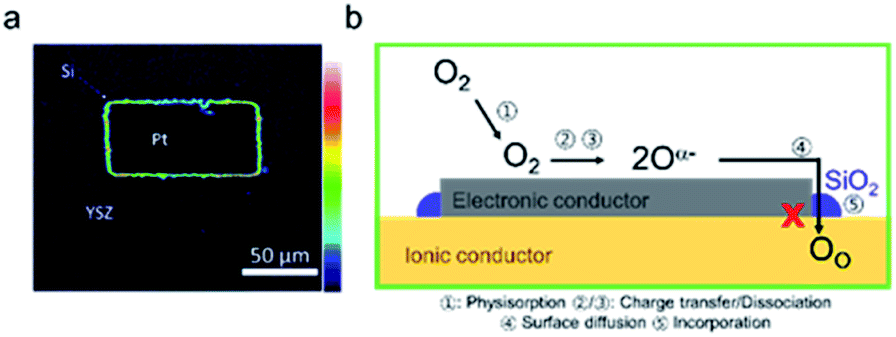
The lambda probe, a potentiometric oxygen gas sensor, is integrated into tens of millions of automobile engines produced annually.25 Typically, the cell, operated at temperatures above 300 °C, shown in cross section in Fig. 2a, is composed of a dense oxygen ion conducting electrolyte, sandwiched between two porous platinum electrodes, that are catalytically active for the oxygen reduction reaction in air (high PO2) and the fuel oxidation reaction on the exhaust gas side (low PO2). This Nernst type concentration cell, operated in open circuit mode, separates exhaust and reference air atmospheres.26 The corresponding Nernst voltage EN generated between the two electrodes,27 see Fig. 2a, is given by, | (3) |
 the oxygen partial pressures in the exhaust and air reference respectively.26,28 Key to establishing a meaningful EN, is achieving equilibrium between the reducing gases (e.g. hydrocarbon and CO) and the oxidizing gases (e.g. O2) at the exhaust gas and oxygen sides of the cell, respectively. The interaction with oxygen involves five steps. Steps 1–3 are analogous to those in described for SMOX sensors. In the Nernst cell, however, in step 4, charged surface oxygen species can diffuse on the surface and in step 5, incorporate into the oxygen ion conducting electrolyte at the triple-phase boundary (TPB), that corresponds to the contact between the electrolyte, the metal electrodes, and the oxygen gas (marked with a star in Fig. 2d).29
 | ||
| Fig. 2 (a) Dense solid electrolyte sandwiched between catalytic porous electrodes maintained between two different oxygen partial pressures. (b) Schematic of a SOFC with the top oxygen electrode (cathode) either a cermet composite composed of an electronic and an ionic conductor (left) or a MIEC (right) while the bottom fuel electrode is the common Ni-YSZ cermet. (c) Schematic of an oxygen permeation membrane. (d) Adsorbed oxygen dissociates, diffuses and becomes reduced via charge transfer from electrode and becomes absorbed into the electrolyte. The surface of the electrolyte is brought into equilibrium with the oxygen partial pressure in the gas phase with the aid of a catalytic electrode like Pt with activity often localized in the vicinity of the triple-phase-boundary designated by a star in the figure. (e) Schematic displaying the surface oxygen incorporation reaction in atmospheric oxygen on the MIEC surface. | ||
SOFCs and SOECs are made up of three main components, a dense oxygen ion conducting electrolyte, a porous cathode and anode. The processes key to SOFC operation are described in further detail here (a SOEC is simply a SOFC operated in regenerative mode), see Fig. 2b. In a SOFC, the oxidation of a fuel through a pair of redox reactions that occur at the corresponding electrodes results in an electron flow (Fig. 2b) through the external circuit (distinguishable from the Nernst cell).30 The oxygen reduction reaction (ORR) takes place at the cathode and the fuel oxidation reaction occurs at anode.31,32 Two types of electrodes are commonly used in solid oxide cells. One is a composite electrode (made up of a metallic and an ionic conductor) and the other, either a single MIEC oxide or a composite. In the typical anode, a Ni-YSZ ceramic-metal (cermet) composite is utilized, while a common composite cathode is composed of a (La,Sr)MnO3 (LSM) and YSZ composite.33 The fuel oxidation and oxygen reduction reactions are confined close to the TPBs, as in Fig. 2d. On the other hand, in MIEC oxides such as (La,Sr)(Co,Fe)O3 (LSCF) and (Pr,Ce)O2−δ (PCO), oxygen can be reduced and directly incorporated into the MIEC oxide lattice anywhere across the electrode surface, as presented in Fig. 2e.34,35 While the electrode structures for SOFCs should be porous, like in SMOX sensors, to ensure a high surface area for reaction with oxygen, they must also exhibit high oxygen ion and electron conductivity to allow for oxygen incorporation and transport away from the oxide surface. The optimal porosity is therefore variable depending on the materials used (32–75%).36
Since the first implementation by Baur and Preis in 1937, the most widely used electrolyte material is yttria-stabilized zirconia (YSZ).37,38 For lower temperatures, as low as 550 C, alternative materials such as Gd doped CeO2 have been utilized.39 Both materials exhibit simple fluorite structures, enabling fast ionic migration, and the incorporation of trivalent acceptor dopants such as Gd3+ and Y3+ increase the oxygen ion conductivity, while suppressing the electronic conductivity by charge compensation through the creation of oxygen vacancies. The transport processes within the electrolyte and MIEC materials are considered in more detail in the subsequent section.
With oxygen being an important feed gas for many industries, the use of dense MIEC oxides, as membranes for oxygen separation, shows great promise, Fig. 2c.40 The current state of the art for the generation of pure oxygen is by cryogenic distillation of air, a costly process.41 Dense MIEC membranes can potentially yield high-purity oxygen with higher energy efficiency and at lower cost.41 The overall rate at which oxygen permeates through a dense ceramic membrane is controlled by the ambipolar flux of negative electrons and positive oxygen vacancies that, for the most part, depends on the rate of diffusion of the slower oxygen conducting species. Overall, this mechanism is similar to that of the SOFC. It is limited, on the one hand, by the diffusion of oxygen ions through the electrolyte, and, on the other, the rate of interfacial oxygen ion exchange. One key difference is the path taken by the electrons, i.e., via the outer electrical circuit in SOFCs and via internal transfer within the membrane in permeation cells (compare Fig. 2b and c).40 From this brief examination of the operation of the different metal oxide devices, in which the interaction with atmospheric oxygen plays a central role, it can be seen that the basic surface reactions are similar. In all cases Si-species have been reported to lead to detrimental effects on performance. Due to the similarity between the processes involved in these applications, the literature examining Si-poisoning will be reviewed together and generally applicable mechanisms and trends identified.
Oxygen ion conduction (grain boundaries and other internal interfaces)
The “Brick Layer model” is commonly used to describe charge transport of both ionic and electronic species in polycrystalline ceramics (Fig. 3a).29,42–46 Charge carriers moving through a polycrystalline ceramic can migrate along three different pathways: (1) through the bulk, (2) across grain boundaries or other internal surfaces or (3) along grain boundaries. The relative contribution of each to the total flux of charged species through the ceramic depends on the specific conductivity and on the cross-sectional area of each conduction pathway.47 Nanocrystalline systems, with large grain boundary surface area to volume ratios, are therefore more strongly impacted by grain boundary transport than macro-crystalline bulk samples. While the discussion so far is true for both semiconducting and ionically conducting polycrystalline oxides, we will now focus on oxygen ion conduction in solid electrolytes, e.g. YSZ or GDC. | ||
| Fig. 3 A schematic showing (a) the cross section of a polycrystalline solid typically modelled using (b) the brick-layer model. The arrows indicate the different transport processes (1) rapid “diffusion pipes” along the grain boundary core, (2) across the grain boundary and (3) mass transport through an individual grain. The line thickness is proportional to the conductance of the associated process.42 | ||
While it has long been known and accepted in metals that grain boundary cores can act as rapid “diffusion pipes” (Fig. 3b(1) for mass transport, owing to their high degree of disorder and larger free volumes, this picture is overly simplistic when considered in the context of metal oxide ceramics, given the need to satisfy overall charge neutrality in non-metallic systems.42 Net charge accumulated at grain boundaries, either due to impurity segregation or distinctive localized defect formation energies, can either impede or enhance ion migration due to the depletion or accumulation of mobile defects within the formed space charge regions. For solid electrolytes like zirconia and ceria, grain boundaries blocking transverse migration across the boundaries (Fig. 3b(2)) can make the materials orders of magnitude more resistive. The grain boundary resistance is typically characterized by larger overall activation energies, than that of the bulk (i.e., grain contributions, see Fig. 3b(3)). This leads to increased overall electrolyte resistance, especially at lower temperatures. As a result, higher operating temperatures are needed yielding more rapid degradation, and thereby reducing lifetimes. Large potential drops at grain boundary interfaces can lead to the accumulation of ions above the reference chemical potential of oxygen in air. For example, for high-temperature solid oxide electrolyzers, this can lead to nucleation of oxygen bubbles and voids at grain boundaries. These voids/bubbles can percolate and form cracks leading to delamination of the electrodes.48 It is therefore important to reduce grain boundary resistance in solid electrolytes as much as possible to achieve high performance and longer operating device lifetimes.
When discussing the conductivity of a grain boundary, it is essential to distinguish the macroscopically measured resistance Rgb, as derived from e.g., impedance spectroscopy, and to normalize it by device area A and length L. Thus, the expression for the overall grain boundary resistivity:
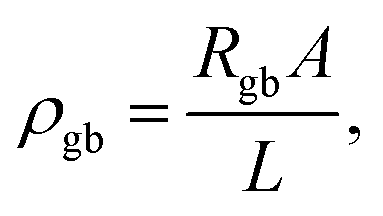 | (4) |
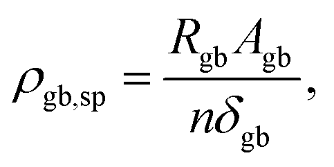 | (5) |
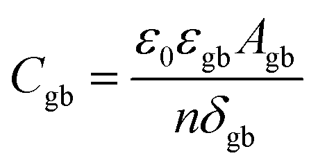 | (6) |
It should be noted that even if in the impedance a relatively small macroscopic grain boundary resistance (average over all the boundaries) is detected, potential drops at specific grain boundaries may still be quite high, which can lead to undesirable degradation mechanisms.
Characterization tools
There is an impressive toolbox of diverse analytical methods available to researchers that can be used to investigate interfacial processes active in electrochemical and related devices. As this is not the main focus of this review, only a brief summary of key methods is provided with a general overview shown in Fig. 4 with the methods separated into three categories, operation measurements, imaging, spectroscopic and relaxation.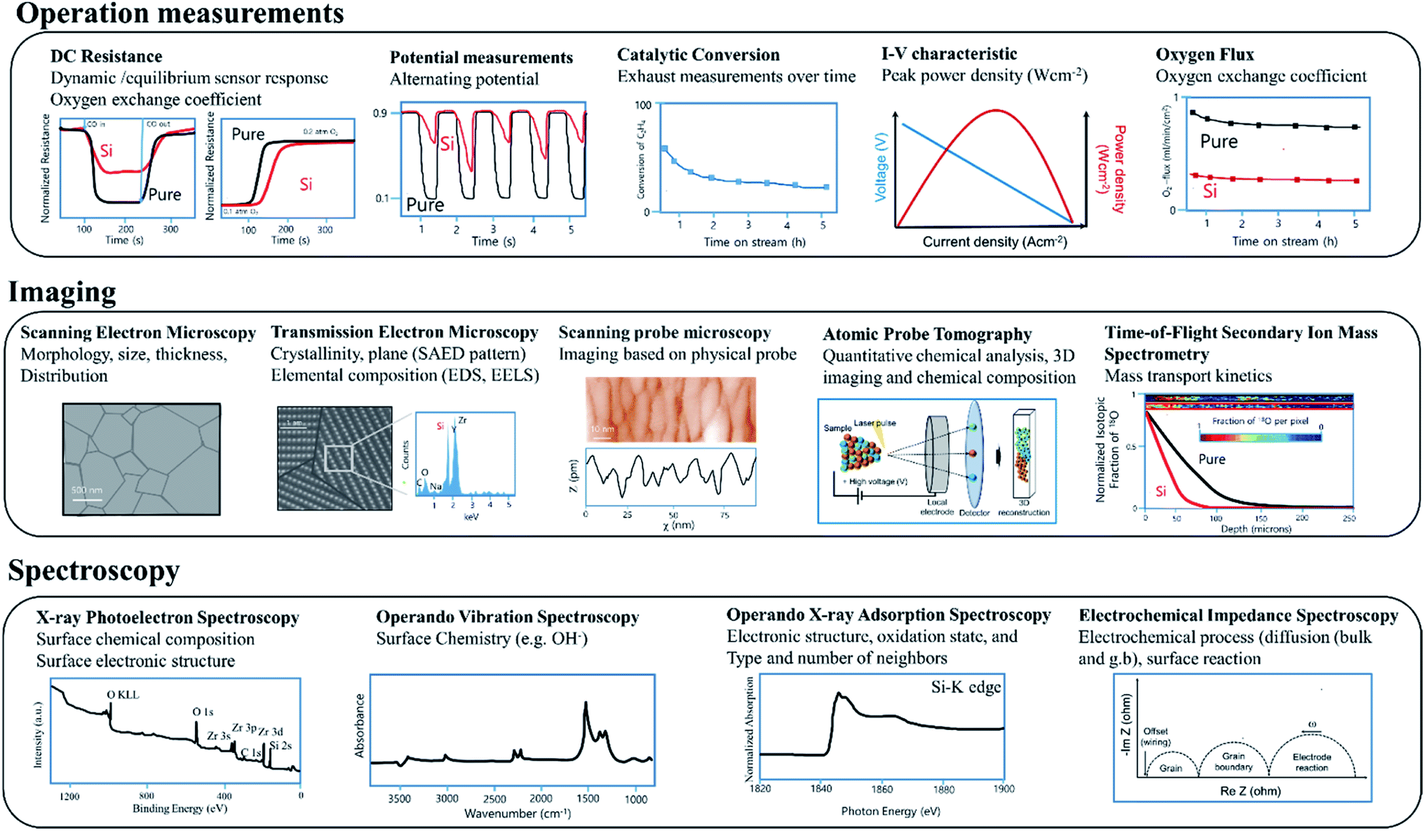 | ||
| Fig. 4 Some of the analytical methods available to researchers used to investigate relevant processes in active electrochemical devices. | ||
Operation measurements
The examination of variations in performance under various operating conditions is key to characterizing underlying behaviour (see operation measurements, Fig. 4). For SMOX based sensors, DC resistance measurements performed on devices exposed to different atmospheres are widely used.24,49 For example, information about changes in reaction rates can be gained by examining changes in dynamic response to either variations in temperature or surrounding atmosphere.50,51 Oxygen surface exchange reaction rates and oxygen chemical diffusivities are also commonly derived from DC conductivity relaxation measurements performed on MIEC oxides, the rate at which the resistance of the materials equilibrates following a rapid stepwise change in the surrounding oxygen concentration.52–54Lambda probes are used to monitor the exhaust of cars. For efficient operation of automotive engines, an ideal fuel to air ratio must be maintained (potential measurement = 0.45 V). During normal operation conditions, the voltage of a narrowband lambda probe will alternate between ca. 0.1 and 0.9 V. After Si-poisoning, it has been found that the oscillation becomes irregular and no longer reaches the set threshold value.55
In the case of membrane reactors, in which a permeation membrane has been coupled with a catalyst, poisoning results in decreased catalytic conversion or changes in product stability with time due to the decrease of oxygen flux through the membrane.56 The peak power density of e.g. SOFC significantly decreases as a result of poisoning.57,58
Imaging
Scanning electron microscopy (SEM) and transmission electron microscopy (TEM) are commonly used to examine the micro/nano-structure and composition of metal oxide samples at high resolution (see Imaging, Fig. 4). While typically operated under ultra-high vacuum conditions, sophisticated sample holders now allow in situ examination under controlled gas exposures.59,60 A large number of reviews on the use of microscopy for metal oxide based electrochemical systems are available.61,62 Scanning probe microscopy offers information about surface morphology and ex situ scanning tunnelling microscopy (STM) is extensively used to study the surface chemistry and band structure of e.g. gas sensing relevant metal oxides SnO2, and In2O3.63–65 Cross sectional STM and spectroscopy (XSTM/S) for complex oxide interfaces have proven to be capable of providing local electronic density of states information at the interface with spatial resolution down to the nanometer scale.66 Atom-probe tomography (APT) provides access to the chemical identify of essentially every atom at e.g., individual grain boundaries.67 The recent review of Gault at al. comprehensively covers APT.68 The mass transport kinetics of oxide materials can be derived experimentally using oxygen isotope exchange depth profile technique coupled with secondary ion mass spectrometry (SIMS).69Spectroscopy
X-ray photoelectron spectroscopy (XPS) (see Spectroscopy, Fig. 4) is widely used ex situ to gain information about surface composition. Near ambient pressure XPS promises studies under more realistic operation conditions.70,71 A large number of operando methods have been developed to examine SOFC/SMOX.72–74 In the field of SMOX based gas sensing, operando X-ray adsorption spectroscopy is used to study the oxidations state and structural parameters of surface additives on the interaction with the surrounding atmosphere.75,76Operando vibration spectroscopy, both Raman and diffuse reflectance infrared Fourier transform (DRIFT) are widely used to look at the surface chemistry of SMOX based gas sensor and have recently been used to examine fuel cells.73,77–80 DRIFT spectroscopy is a highly surface sensitive method and therefore provides information about the adsorbates that form as a result of the interaction with the surrounding.81 Raman is less surface sensitive, but provides information about the bulk structure and variations induced by e.g. redox processes.82–84 Electrochemical impedance spectroscopy (EIS) is widely used to deconvolute bulk from interfacial phenomena in metal oxide electrochemical systems in situ and operando and provide equivalent circuit elements corresponding to various kinetic processes.85Silica as a potential poison
Si-impurities are known to result in significant degradation of metal-oxide based systems. Si-based impurities are ubiquitous in metal oxide processing and testing, e.g. originating from furnace refractories or Si-based sealants/greases.41,56,86–92 In addition to processing sources, Si-impurities are also omnipresent in the environment. Volatile organic silicon compounds (VOSCs) are widely used in consumer goods such as electronics, furniture, healthcare, pharmaceuticals, cosmetics, and cookware,93 leading to significantly higher concentrations indoors than outdoors.94–96 Over the last decades, a great deal of effort has been invested in identifying Si-impurity sources and developing means for avoiding contamination. For example, van Berkel et al. prevented Si-poisoning in oxygen permeation membrane measurements by avoiding VOSC containing grease in the manual valves of the experimental setup.56 In some applications, however, VOSCs are inherently present and must be actively removed to evade degradation. For example, when fuel cells are implemented using biogas from waste-water and landfills, active carbon filters have been implemented.97 Likewise, VOSCs must be removed prior to exposure of lambda probes to exhaust gases generated in bio-gas combustion engines.98In the following sections, we review the models developed to explain the detrimental effects of Si-impurities on both surface reactivity and the transport properties of grain boundaries. In early discussions of potential Si-based poisoning, as the impurity concentrations were very high, the most widely used models assumed the existence of continuous Si-rich blocking layers that increased grain boundary resistance and blocked oxygen gas diffusion to the reactive surface. To avoid formation of the impervious glassy layer, researchers began to use higher purity precursors and to avoid VOSC containing materials. Although greatly reduced in concentration, Si-impurities remained present due to their pervasive nature. Surprisingly, significant degradation remained, proving that the glassy blocking layer model was not appropriate in all cases. Recent findings indicate that both at the grain boundaries, and on the surface, the negative effects of Si-impurities are related to their role in the formation of space charge regions, not necessarily physically blocking second phase layers. Additionally, on the surface, VOSCs have been found to deactivate chemically-different surface sites at varying rates. Based on both the original impervious layer model and the more comprehensive models that account for space charge regions, methods to compensate for Si-poisoning have been developed. A more detailed review of the poisoning mechanisms and mitigation methods as well as the potential pitfalls, will be highlighted in the following section.
Si-poisoning mechanisms
Despite being a widespread problem, the mechanisms responsible for the detrimental effects of silica on the operation of metal oxide devices relying on oxygen adsorption, exchange and diffusion, remain controversial. In the following, we review how silica poisoning can reportedly impede two critical aspects of metal oxide performance: grain boundary conductivity and surface reactivity.Oxygen ion conduction (grain boundaries and other internal interfaces)
In the last three decades, the origin of silica poisoning at grain boundaries has been the focus of a large body of work in the field of solid-state ionics. Originally, impurity levels in precursor powders were high. Silica was even intentionally added as a sintering aid to help lower sintering temperatures via the formation of intergranular liquid phases99–101 or to impart high-temperature super-plasticity.102 The siliceous phase was believed to melt during sintering temperatures and evenly coat the granular particles during sintering.87,103–105 As a result, it was believed that continuous ionically insulating phases formed at the grain boundaries, even visible, in some cases using electron microscopy, were the main reason for grain boundary blocking, Fig. 5a.29,43–45,106 The attribution to a continuous Si-rich blocking phase (modelled in Fig. 5b), however, remained contentious as (1) the amorphous phase rarely was found to evenly coat the full grain boundary, (2) the activation energy of the grain boundary did not seem to depend on the amount and chemical nature of the siliceous phase and (3) even in relatively high purity samples, the lower frequency grain boundary contribution remained present in impedance plots (Fig. 5a). It was even demonstrated that, while squeezing the secondary phase out towards the triple junctions, by application of pressure during sintering, decreased grain boundary resistance by an order of magnitude, the activation energy barely changed.107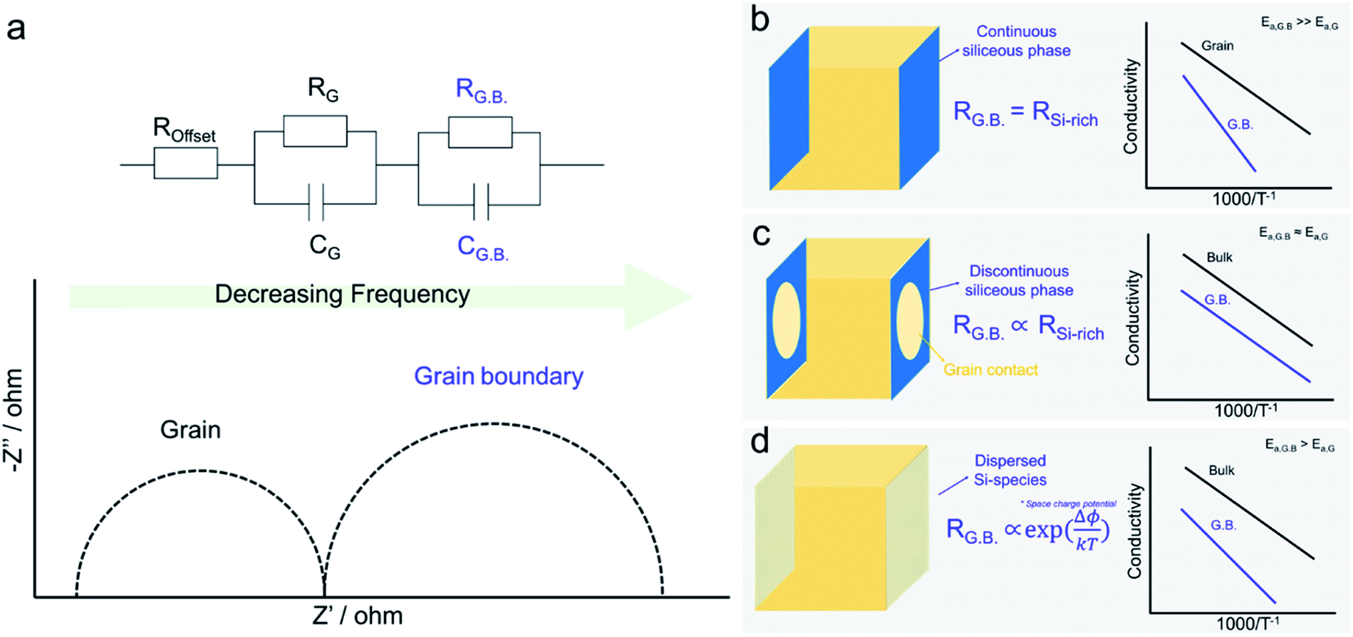 | ||
| Fig. 5 (a) Complex impedance spectra showing a higher and lower frequency semicircle attributed to the grain and grain boundary contributions, respectively. (b) Brick-layer model for highly resistive grain boundaries due to continuous Si-rich glassy blocking layer. The grain boundary resistance activation energy is tied to the insulating glassy layer and therefore should be significantly higher than that of the bulk. (c) Brick-layer model in the case of a non-continuous Si-rich blocking layer. Simplistically, the blocking layer is considered non-active but causes current constriction (the current passes through the remaining grain–grain contact) which results in the increased resistance of the grain boundary. In this case the activation energy of the grain boundary should be identical to that of the grain bulk. (d) Brick-layer model in the case of dilute Si-species dispersed uniformly in the grain boundary core leading to a positively charged core and the formation of a space charge barrier Δϕ leading to a conductivity activation energy higher than that of the bulk. | ||
To address the discrepancies between theory and experiment, more complex models were developed to describe the formation of a discontinuous Si-rich grain boundary phase. The simplest model considered the simultaneous presence of both Si-rich blocking and unaffected direct grain to grain contact regions, leading to two parallel paths for conduction; one through the grain to grain contact and the other through the insulting silica phase. Both Kleitz et al.108, Fleig and Maier109 refined the brick layer model to address the situation where an insulating phase partially wets the grain boundary area. While the Si-rich phase was assumed to be highly insulating and therefore not significantly contributing to conduction, it did, however, serve to reduce the effective area of the grain-to-grain contact, thus creating a “constriction” effect at the boundary.110 The grain boundary activation energy is then determined by the grain-to-grain contact region, that should be similar to that of the grain bulk (slight variations due to e.g. lattice mismatching, dislocations, defects, and enhanced segregation of bulk components), and is independent of changes in the glassy phase, as represented in Fig. 5c. While this model could indeed explain the observed behaviours for samples with large secondary phases present at grain boundaries, it could still not fully explain why even at very low impurity concentrations, the grain boundary resistance and activation energy remained higher than that of the bulk. Indeed Aoki et al. found that even when grain boundaries possessed <0.1 monolayer of segregated Si, the grain boundary remained 102 times more resistive than the bulk, which the authors attributed simply to an “intrinsic limitation”, see in Fig. 5d.106
Since then, through efforts of powder purification, it has been shown that the “intrinsic” resistance of grain boundaries in YSZ and acceptor doped CeO2 are related to space charge effects. The space charge model describes a grain boundary as consisting of an electrostatically charged core and two adjacent space charge layers, compensating the core charge. It remains contested whether the grain boundary core charge is due to impurity segregation or the intrinsic excess of positively charged oxygen vacancies due to lower defect formation energies at the boundaries.67 Regardless of the origin, macroscopically it can be assumed that the interface is net charged. To maintain global electroneutrality, this requires redistribution of mobile ionic defect within the vicinity of the interface to shield the electrostatic potential. The spatial profile of the defects c(x) are tied exponentially to the space charge potential Δϕ via the following relation
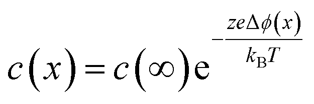 | (7) |
In which c(∞) is the concentration of the defect in the bulk outside of the space charge region, ze the net charge of the defect, and kB and T the Boltzmann constant and temperature in Kelvin respectively. For a positively charged interface, at sufficiently high temperatures, this leads to both the accumulation of acceptor dopants with effective negative charges and the depletion of oxygen vacancies with effective positive charges near the grain boundary (so-called Gouy Chapman treatment, see Fig. 6 left).46 At lower temperatures, when the acceptor dopants are not sufficiently mobile, this results primarily in depletion of the mobile positively charged oxygen vacancies (so-called Mott Schottky approximation, schematically displayed Fig. 6 right). The properties of these space charge zones are described by solving the Poisson equation and constraining the system to achieve global electroneutrality. This yields a characteristic length, eqn (2) called the Debye length LD, which depends inversely on the square root of the dopant concentration in the bulk  (i.e. the ionic strength):
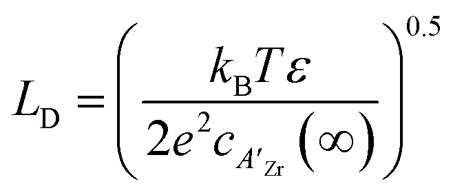 | (8) |
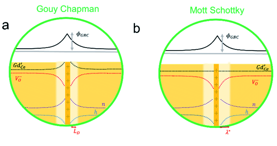 | ||
| Fig. 6 These schematics show how the concentrations vary as a result of the space charge potential. (a) The Gouy–Chapman model is used to describe a positively charged interface, at sufficiently high temperatures, resulting in the accumulation of both acceptors dopants with an effective negative charge and the depletion of oxygen vacancies with effective positive charges near the grain boundary. (b) The Mott Schottky model describes the situation at lower temperatures, when the acceptor dopants are not mobile and a depletion of the positively charged oxygen vacancies primarily results. | ||
This dictates the length scales over which the mobile ionic defects redistribute in the adjacent grain to shield the interface charges. Under constrained equilibrium conditions, where cations are not mobile due to low temperatures processing, this characteristic length scale changes to λ* as defined in eqn (3).
 | (9) |
Both the characteristic length scale, and the space charge potential, shrink with increasing dopant concentration. This model explains the relatively low grain-boundary conductivity in less highly doped materials. In series, the impact of space charge on the total resistivity can be related to the bulk resistivity and the modulation of the carrier concentration compared to the bulk:46
 | (10) |
With this understanding, Kilner et al.111 hypothesized that at low Si-concentrations, the grain boundary resistance originates from a space charge region (modelled in Fig. 5d), and at higher concentrations, the constriction model is accurate. In this study, the grain boundary resistance of Gd doped CeO2 was examined as a function of silica concentration (30, 200 and 3000 ppm) in samples with varying concentrations of the Gd acceptor dopant. At low silica concentrations, two explanations have been provided to explain the source for the grain boundary conductivity decreasing sharply with increasing Gd content. The first relates to eqn (8) and the decrease in Debye length, while the second, relates to the incorporation of the negatively charged dopant into the grain boundary core, compensating, in part, the positive charge.112 At high Si-concentrations, the authors report no continuous siliceous phase at the grain boundary; instead Si-phases were found to concentrate at three-grain junctions, and in this case, the authors argue that the constriction model applies (see Fig. 5c).
The decrease in grain boundary resistance due to dopant segregation, counteracting partially the net charge at the interface, has been the focus of recent work by Xu et al.67 Ionic defect segregation from the bulk lattice to the interface is driven by thermodynamic driving forces, including minimization of strain and electrostatic interactions, which in turn, can depend on grain misorientation angle and surface crystal orientation.42 In their work, Xu et al. mapped out the electric field potentials at various grain boundaries by electron holography in highly purified 0.2 atom% Sm doped CeO2 samples and found variations in space charge potential as high as ∼1 eV. Combined with atom probe tomography, they also found that different grain boundaries exhibited a significant variation in the level of cationic impurities such as Al, Mg, Ca, Ba and Si. By assigning effective charges to the cations, and summing their concentrations, they estimated the net interface charge density locally and derived from that the electrical potential. They observed a strong correlation between the experimentally measured space charge potentials and the measured impurity concentrations. Silicon and aluminium, due to their small ionic radii, are expected to enter lattice sites within the boundaries interstitially and possess 4+ and 3 + positive charges respectively, thus contributing strongly to the space charge potential. This finding runs contrary to the more commonly assumed source of excess positive charge at the grain boundary core, i.e., that coming from excess oxygen deficiency, driven by lower reduction energies at the grain boundaries.113
Oxygen reduction and exchange reactions
As for grain boundaries, surface Si-impurities are widely reported to degrade metal oxide based electrochemical devices. Due to initial low precursor purity, high Si-impurities on the surface were initially studied, similar to the situation in earlier grain boundary studies.114 Recently, due to the large levels of VOSCs in certain applications e.g. biogas, the effects of high Si-concentrations on surface reactivity has gained renewed interest.55,97 Some of the earliest work on Si-poisoning was done in the context of the potentiometric oxygen sensor (lambda probe). Degraded devices were often found to have a characteristic grey coating, see Fig. 7a inset. Holleboom et al. attribute this grey coating to a glassy Si-layer that does not modify the exchange process, but rather reduces the rate of oxygen gas phase diffusion to the active surface, see Fig. 7a.55,86,114,115 They argue that, while large molecules such as oxygen are hindered, small molecules such as hydrogen should easily be able to pass through the blocking layer.55,86,114,115 Based on this idea, numerous authors have reported the increased selectivity of SMOX based gas sensors following physical deposition (e.g. using screen printing) of a continuous silica layer on top of the sensitive SMOX layer (Fig. 7b, left and c).116,117 Lower surface band bending is expected due to hindered oxygen gas diffusion through the filtering Si-layer. Due to the high porosity of the SMOX sensitive layer (>70%), exposure to VOSCs should not form a continuous silica layer on top of the sensitive metal oxide, but rather should coat the individual grain surfaces (Fig. 7b, left and d).116,117 In this case, continuous Si-layers will not only block diffusion of oxygen to the surface, but will serve to degrade the electronic contact between grains, explaining the increased baseline resistance seen following long-term exposure to VOSCs, Fig. 7d.95,115,118–120 After long-term operation in Si-rich atmospheres, the characteristic grey coating has also been seen on MIEC membranes and SOFC cathodes (Fig. 7e). As a result, the formation of continuous Si-rich layer limiting diffusion of oxygen to the surface has also been cited as the degradation mechanism of MIEC both for membranes and for SOFC cathodes (Fig. 7f). In the case of stable materials, e.g. fluorites, the formation of a silica phase is assumed.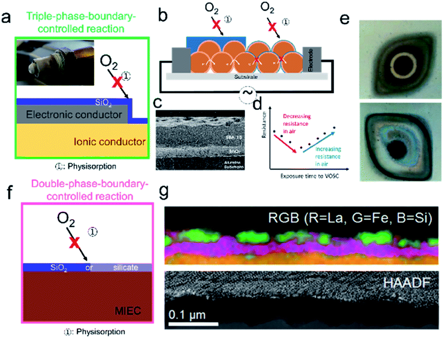 | ||
| Fig. 7 Models developed to depict high concentrations of surface silica. (a) Schematic of completely SiO2 blocking layer preventing adsorption of oxygen on the surface of either the electronic conducting electrode or the ionic conducing electrolyte. (inset) A degraded Lambda probe shows the characteristic grey layer, courtesy of Martijn Van essen, from Det Norske Veritas, Groningen, The Netherlands. (b, left) SiO2 diffusion layer physically deposited onto the top of the sensitive n-type metal oxide layer to limit the diffusion of large gas molecules, increasing sensitivity to H2. (b, right) Due to their high porosity, exposure of the SMOX sensitive layer to VOSCs results instead in a continuous SiO2 layer on top of the metal oxide grains degrading intergranular electrical contact. (c) SEM cross-section of SiO2 layer screen printed onto SnO2. Reprinted from ref. 16 with permission from Elsevier. (d) Initial exposure to VOSCs decreases the baseline resistance, with resistance increasing at longer exposure to VOSCs, indicating degraded electronic contact between grains.95 (e, top) The feed (e, bottom) and the permeate sides of a LSCF membrane after a permeation experiment of 1000 h. Permeate side shows the characteristic grey Si-layer. Reprinted from ref. 56 with permission from Elsevier. (f) In the case of double phase boundaries, the blocking layer has been reported to be made up of a combination of SiO2, as well as silicates that forms as a result of the reaction of silica with the surface of the MIEC. (g) Cross-sectional STEM-HAADF image and elemental distribution maps of silicon poisoned LSCF electrode obtained by EELS and EDXS. It can be seen that not only does a complete Si-rich blocking layer form on the surface but that the MIEC decomposes and forms lanthanum silicate and iron oxide clusters. Reprinted from ref. 121 with permission from Elsevier. | ||
For the more commonly used, but less stable perovskite electrodes, degradation is two-fold. For example, after operation in a highly humid Si-rich atmosphere, lanthanum strontium cobalt ferrite (LSCF) showed evidence of decomposition as reflected in its surface becoming coated in a 30–40 nm thick La-silicate layer (pink in Fig. 7g), on-top of which nanoparticles of (Fe,Co)xOy were detected.34,121,122 In addition to the formation of a glassy layer limiting oxygen gas diffusion to the surface, decomposition of the base oxides may be responsible for the decreased reactivity. Similar results have been reported for BaCe0.1Co0.4Fe0.5O3−δ based oxygen permeation membranes.56,123
Even for silica concentrations below that needed to achieve complete surface coverage, degradation has been reported. Using time-of-flight secondary ion mass spectrometry (ToF-SIMS) measurements, Optiz et al. were able to identify the accumulation of Si-species at the TPB of Pt/YSZ/O2 that had been highly polarized and exhibited performance degradation, Fig. 8a.124,125 Similar silica accumulation has been reported for the YSZ|Ni anode interface.126 Hertz et al. showed that etching the surface of YSZ single crystals, with interdigitated Pt thin film electrodes, with concentrated hydrofluoric acid, improved performance by as much as three orders of magnitude. They attributed this improvement to the removal of silica from the Pt/YSZ/O2 TPBs.87 Mutoro et al. used pulsed laser deposition (PLD) to selectively contaminate YSZ substrates with Pt electrodes in different controlled regions with SiO2. They found that while a SiO2 interlayer between the YSZ and Pt resulted in a significant decrease in the exchange current density, the effect of SiO2 deposited on the surface of the Pt electrode itself had only a low (even positive) impact on the exchange current density.127,128 Based on the above results, it is reasonable to conclude that the TPB is particularly vulnerable to Si-deposits, resulting in performance degradation by blocking the oxygen insertion step, Fig. 7b. In MIEC samples, even if the oxygen insertion is not confined to the TPBs, significant deactivation is observed without full surface coverage. Though the formation of space charge regions has been attributed to Si-impurities at grain boundaries, this aspect has been largely ignored with regard to surface activity. Surface additives, are well known to contribute to the generation of space charge regions adjacent to the surfaces of semiconducting or mixed conducting solids, e.g. for noble metal additives on the surface of SMOX gas sensors.129–131 The authors recently reported the ability to predict whether a surface binary oxide additive on the surface of mixed conducting Pr0.1Ce0.9O2−δ would result in surface electron depletion or accumulation, depending on its Smith acidity factor (Fig. 9b) relative to the pristine oxide.132 Indeed, while the oxygen exchange rate kchem was found to be suppressed by a factor of roughly 220 by strongly acidic SiO2, strongly basic additive Li2O, resulted in a thousand-fold increase, Fig. 9a.
 | ||
| Fig. 8 (a) Accumulation of Si at the TPB of the polarized electrode (over potential η = −2.22 V at 303 °C for 10 min). Reprinted from ref. 125 with permission from Elsevier. (b) Si-agglomeration at the TPB causes degradation by blocking the oxygen insertion step. | ||
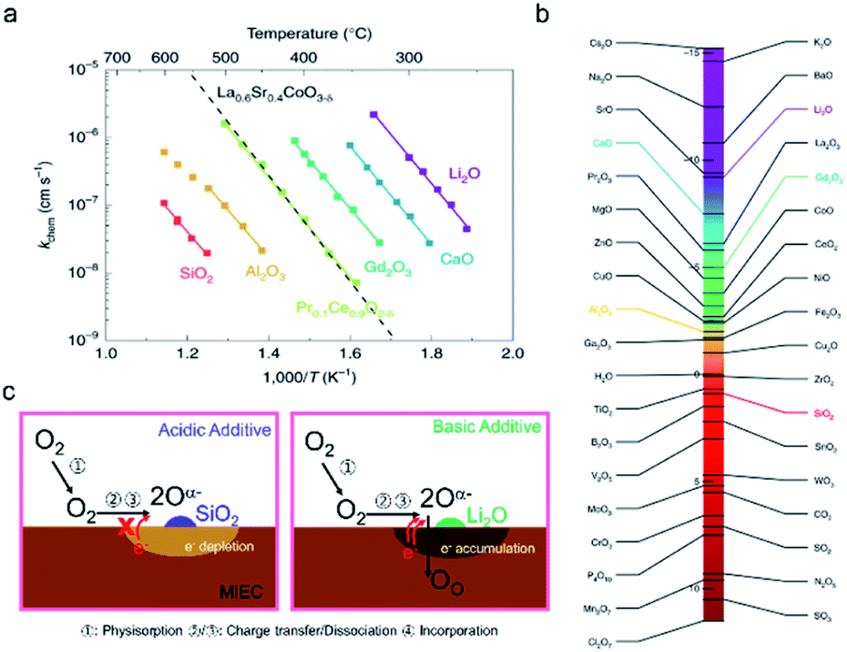 | ||
| Fig. 9 (a) Oxygen chemical surface exchange coefficients of PCO as a function of reciprocal temperature for various surface modifications with selected binary oxides.92 (b) Acidity scale for binary oxides, as proposed by Smith.133 H2O is chosen as the origin—positive values are acidic while negative values are basic. (a and b) Reprinted from ref. 132 with permission from The Author(s), under exclusive licence to Springer Nature Limited. (c: left) Schematic of electron depletion region induced by acidic SiO2 and (c: right) of electron accumulation layer induced by basic surface additive Li2O. | ||
More generally, the authors demonstrated that the Smith acidity scale allows one to predict, a priori, the effect of binary oxide additives on the oxygen exchange rates of mixed conducting oxides.132 Moreover, the negative impact of Si-poisons on kchem occurred even though surface coverage of the Si-poison was not continuous. No change in the activation energy was found, unlike recent studies in which thin siliceous layers significantly degraded performance and practically doubled the activation energy.134 Overall these results indicate an electron depletion model rather than one depending on blockage of oxygen transport to the interface. As a result of the electron depletion layer, charge transfer to oxygen (step 3) is hindered, Fig. 9c, left. On the other hand, lithia leads to enhanced exchange, Fig. 9c, right. While surface poisoning mechanisms have largely mirrored those proposed for grain boundaries, at the surface an additional key feature must be considered, i.e., the varying reactivity of different adsorption sites with the surrounding atmosphere. For example, metal cations are Lewis acid sites while hydroxyl groups can act as either Brønsted base or acid sites depending on how tightly they are bound.135 How VOSCs interact chemically with the metal oxide surface is often neglected in the literature. Williams and Pratt, and Schultealbert et al., both found that exposure to VOSCs deactivate different surface sites on SnO2 and at varying rates (Fig. 10a).95,96 The transient response to all gases slows down as a result of Si poisoning, but the active sites for hydrogen appear to be deactivated to a lesser degree than those for the other gases (Fig. 10b).
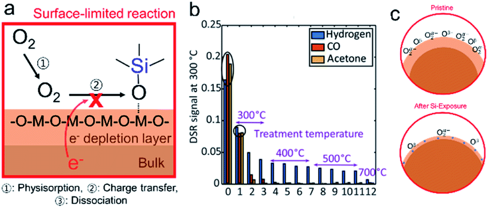 | ||
| Fig. 10 (a) Schematic showing how adsorption of VOSCs hinders reaction with oxygen. (b) Transient SnO2-based MOS gas sensor (UST GGS 1530, UST Umweltsensortechnik GmbH) sensor signal at 300 °C plotted for the three measured gases at 2 ppm for several treatment temperatures. Reprinted from ref. 96. This work is distributed under the Creative Commons. (c) The space charge region at the surface could decrease as a result of exposure to VOSCs as oxygen adsorption sites become blocked by Si-species. | ||
The authors argue that the high selectivity, and even increased steady state response to hydrogen, results from the fact that the re-adsorption of oxygen is more strongly hindered by the adsorption of VOSCs than the reduction by hydrogen. This is also in line with the reported decrease of the baseline resistance in air at low Si-impurity concentrations, i.e. the preferential sites for oxygen adsorption are blocked, and therefore surface band bending and resulting inter-grain potential barrier heights are decreased relative to those in the pristine case Fig. 10c.95,120 These results indicate that VOSCs do not indiscriminately react with the surface, but rather have preferential adsorption sites. Controlling the surface chemistry therefore offers an avenue for rendering samples more robust against poisoning by VSOCs and thus deserves further investigation
Poisoning mechanisms – overview
The understanding of Si-poisoning at metal oxide grain boundaries and surfaces has developed along similar lines, an overview of the mechanisms is given in Fig. 13. Initially, samples with high Si-concentrations, resulting from intentional additives as sintering agents or from various other sources (e.g., greases or fuel contamination) led to the formation of continuous glassy layers, supporting a model that correlated decreased performance with the physical blocking of oxygen species by the glassy phases. Even for Si-concentrations too low to form continuous layers, however, significant negative impacts on performance have been reported. For grain boundaries, the formation of inactive, but non-continuous blocking Si-layers, constricted current flow between grains. On surfaces, Si-species were hypothesized to preferentially block certain surface or interface adsorption sites, e.g. the TPBs or surface hydroxyl groups. Even in nominally pure materials, grain boundaries were found to have a significantly higher resistance than the grains. Kilner et al. among others attributed this “intrinsic limitation” to the existence of space charge regions adjacent to the grain boundaries.111 Recently, Xu et al. reported that the source of these space charge regions could be attributed to interstitial incorporation of small cations such as Si4+ and Al3+ into the grain boundary core creating a net positive core charge.67 Recent findings indicate that finely dispersed high acidity Si-species also contribute to the formation of space charge regions (electron depleted) on the surface, decreasing oxygen exchange kinetics.132 Despite the widespread detrimental effects of Si-species on performance of a variety of metal oxides devices, the poisoning mechanisms remain controversial. In the following, we discuss proposed methods to compensate or protect against Si-based poisons as well as progress in identifying or refining the poisoning mechanisms.Compensation methods
Oxygen ion conduction (grain boundaries and other internal interfaces)
The configuration, wetting behaviour, and composition of impurity phases all impact the magnitude of the grain boundary resistance. A variety of methods, i.e., thermal annealing, application of pressure during sintering and additive scavenging that drives Si-agglomeration can all contribute to lowering the level of degradation, see Fig. 11a. When secondary phases are present, resulting in constriction effects, strategies that can modify the wetting of the grains appear most effective. For example, heat treatments have been used to modify the amount of grain boundary surface area wet by silicate phases. Lee et al. showed that for 8YSZ, a pre-sintering heat treatment at 1200 C for >10 h, prior to sintering for 1600 C for 4 h, could help decrease the grain boundary resistance.136–138 The authors noted that the optimum pre-sintering temperature coincided with the nucleation temperature of ZrSiO4, although it was limited to small impurity concentrations (<400 ppm SiO2). Alternative approaches to precursor scavenging have relied on applied pressure at high temperature, during creep experiments, to “squeeze” the impurity phases towards the triple junctions, see Fig. 11a.107 Alternatively, the addition of small amounts of impurities that preferentially react with the Si-impurities, resulting in their agglomeration at triple junctions, can help reduce constriction effects (Fig. 11a). Due to their higher affinity for Si than for ZrO2, Al2O3,138 Fe2O3,139 Bi2O3,140 and MgO141 have been extensively studied as scavengers as reviewed by Lee et al.142 Using scavengers to successfully reduce grain boundary resistance is not, however, always predictable. First, the scavenging process was found to be sensitively dependent on how dispersed the scavenger was within the raw powder, as the grain boundary diffusion of the Si-phase seems to control the scavenging mechanism.143 Likewise, the incorporation of additives like Al2O3 to scavenge Si is only effective for small amounts of Si before the additive begins to impact the bulk conductivity of the material and/or generates new insulating phases.29 Moreover, cross-reactivity between dopants, impurities, and scavengers can also lead to additional insulating phases forming. For example, Kilner et al. investigated the impact of sintering aids such as Co2O3, Fe2O3 and Mn2O3 on the total conductivity of Gd doped CeO2 with deliberately added SiO2 impurities.139 They found that Co2O3 and Mn2O3 typically have a very deleterious impact on the grain boundary resistance, by the formation of secondary glassy insulating phases, while Fe2O3 did not. This emphasizes the necessity of considering the chemical affinities between the silica, the precursor additives and any other potential impurities present in high concentration.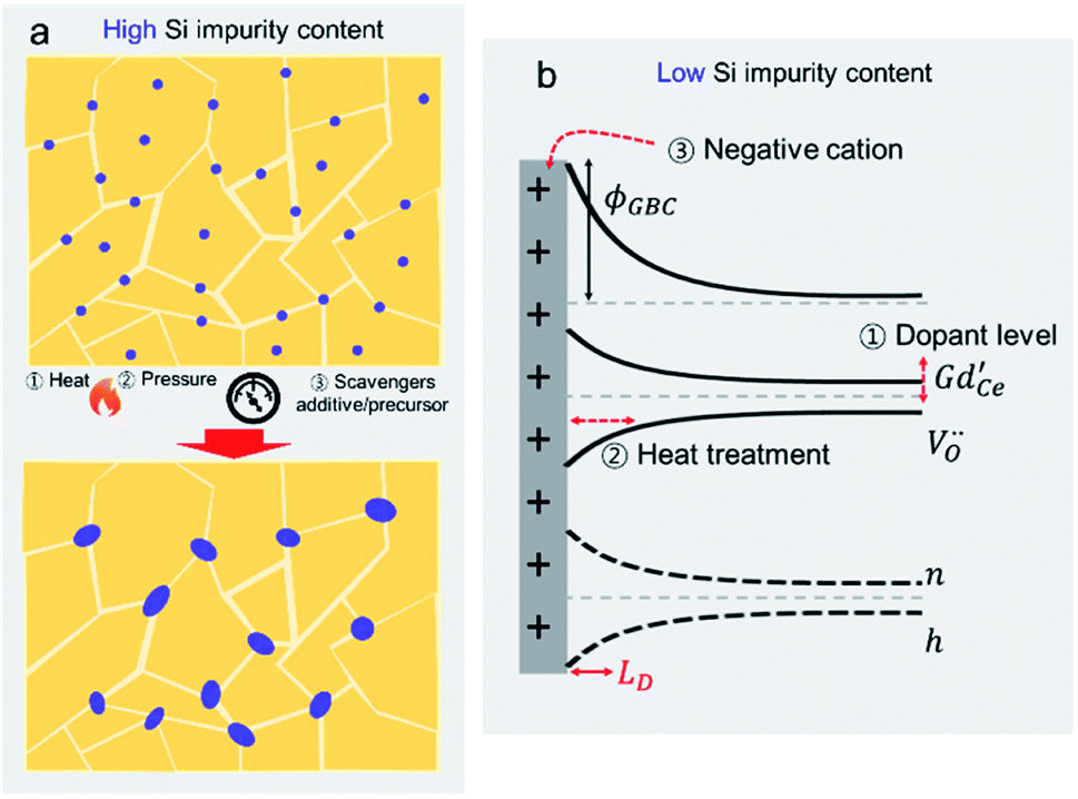 | ||
| Fig. 11 (a) Compensation methods used to reduce the impact of high Si-impurity concentrations at grain boundaries. Methods such as pressure or heat, as well as scavengers have been used to drive agglomeration of Si-species to the triple junction. (b) Space charge model illustrating compensation of positively charged Si-species at grain boundary core by redistribution of mobile charge carriers with space charge region adjacent to grain boundary. | ||
Finally, even if the additive scavenging strategy is successful at segregating large insulating phases towards the triple points, the additive on an elemental level can still result in an intrinsically higher grain boundary resistance. For example, while Al2O3 has been proposed as the most effective scavenging precursor, there is also indications that Al contributes to the formation of the space charge potential at grain boundaries, due to its net positive charge within the grain boundary, thus not making it an ideal candidate for eliminating the grain boundary resistance.67 Generally, the strategy of additive scavenging is a sensitive process that depends on the concentrations of other impurities and the sintering temperature. Using scavengers not only inherently increases the level of impurities, but is often associated with additional processing steps to improve powder homogeneity that can result, in turn, in additional contaminants. Therefore, avoiding Si-impurities in the base material, and during the processing steps, is the most effective solution in preventing the formation of secondary phases that can act as constrictors. Additional strategies are subsequently needed to modulate the intrinsic grain boundary resistance, as it relates to the space charge properties, as we discuss next.
One of the most common strategies to mitigate space charge effects relies on the high acceptor doping of the bulk to increase the ionic strength of the system and decrease the impact of space charge zones. As seen in eqn (8), the Debye length inversely correlates to the dopant concentration in the bulk lattice. Thus, increasing the bulk dopant concentration leads to a shrinkage in the size of the space charge and its width. This can be done extrinsically through doping or intrinsically by reducing the electrolytes under H2/Ar environments in order to generate additional negative charges that compensate the space charge potential, though the later has limited use as it also reduces the ionic transference of solid electrolytes.144 Moreover, the segregation of the negatively charged dopant into the grain boundary core can help counteract the naturally present positive charges (Fig. 11b).67 This strategy can be quite successful as it also increases the bulk conductivity. However, above a certain dopant fraction, the bulk conductivity will begin to decrease which has often been attributed to defect association effects. More recent theoretical considerations have challenged this perspective and describe the conductivity decrease to arise from a change in barrier height due to the proximity of dopant as nearest neighbour. Generally, this means an optimum dopant level must be found.145
Alternatively, using small amounts of cations with effective negative charge that segregate to the grain boundary would serve to counteract the net grain boundary positive charge and thus provide extrinsic control over the space charge potential, while minimizing its impact on the bulk conductivity. Previous reports of improvement in grain boundary conductivity upon introduction of alkaline earth additives141,146–149 support this hypothesis and direct heterogeneous doping of the interface by in-diffusion of metallic elements has been investigated for this purpose as well.150,151 Negatively charged elements such Ni, Co, and Fe have been selectively diffused into the grain boundaries of polycrystalline acceptor doped CeO2 thin films, leading to decreases in space charge potentials by as much at 20%. Key to this approach is the careful selection of elements that are insoluble in the bulk lattice, but diffuse preferentially at the grain boundaries. We note, however, that this type of strategy is only viable for already purified samples, as shown in the Kilner work,139 as the presence of high concentrations of impurities can lead to undesirable cross reactivity of transition metal additives and the formation of additional insulating phases, increasing the constriction resistance (Fig. 11a and 5c).67
Oxygen reduction and exchange reactions
In most fields, great lengths have been taken to avoid exposure of active surfaces to VOSCs. For example, research is currently being performed with different adsorption options, e.g., active carbon, zeolites etc. to remove VOSCs so as to increase the processing and energy efficiency of biogas; see review by Gaj.97 In the case of the TPB at Ni/YSZ, the effect of silica deposition was successfully reduced using an electrochemical scavenging mechanism. Tao et al. found that when operating a solid oxide cell in electrolysis mode (SOEC), silica precipitates in the nickel grain instead of at the TPB. The authors argue that the silica is reduced to Si under strong cathodic polarization and then diffuses into Ni.152 This principle has not been examined for Pt/YSZ.Few studies exist in which attempts have been made to compensate for Si-impurity induced degradation of the surface oxygen exchange reaction. Prof. Kilner, also here, was a pioneer. After noting that La had previously been shown to reduce the impact of Si on blocking ionic conduction through grain boundaries in acceptor doped ceria, he and colleagues reported that the addition of La to the electrode surface could likewise improve the oxygen exchange rate.153 By monitoring the oxygen exchange kinetics of PCO thin films by an optical transmission relaxation (OTR) technique, a >10 fold increase in oxygen exchange kinetics was observed following deposition of La via PLD on the Si contaminated film surface (Fig. 12a).153 Subsequent work by Zhao et al. examined the effect of different additives on the oxygen exchange kinetics and found that additives that tend to react with Si (e.g., La, Sm oxides) resulted in improved kinetics while those that did not form silicates (e.g., Nb, Ti, Zn oxides), showed no improvement. The improvement was thus attributed to the likely conversion of a dense siliceous phase to a porous phase, leading to volumetric changes and accompanying cracking, thereby allowing oxygen molecules to penetrate and reach the surface of the PCO film (Fig. 12b).91
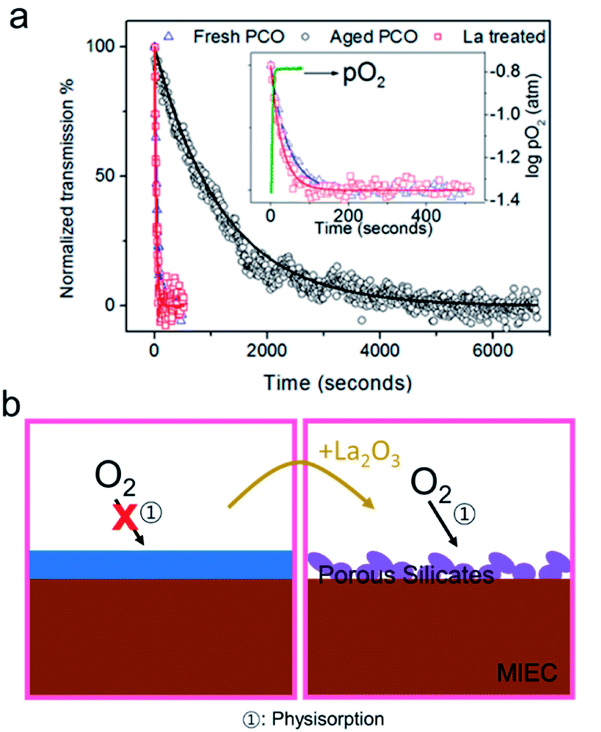 | ||
| Fig. 12 (a) Optical transmission relaxation curve for a fresh, aged and La treated PCO film measured at 600 °C following a PO2 step from 4% O2 to 21% O2. Reprinted (adapted) from ref. 91 with permission from American Chemical Society. (b: left) Schematic of an impervious blocking layer that prevents oxygen diffusion to the surface. (b: right) The interaction between the La-additive and the silica layer results in a porous silicate. | ||
Based on our own recent results in which acidic additives serve to deplete oxide surfaces of electrons and basic additives serve to accumulate electrons, effects beyond morphological changes in Si-rich layers appear responsible.132 On this basis, one can understand why the two “basic” additives like La and Sm would result in better oxygen exchange kinetics on ceria-based systems. On the other hand, titania- and alumina, like silica, are significantly more acidic than ceria and thus would be expected to hinder the oxygen exchange reaction. It thus appears that, in addition to the possible formation of more highly porous layers upon addition of lanthanum, more importantly, it is likely that regions of increased reactivity result from the basic character of lanthanum that serves to compensate regions of lower activity induced by acidic surface species like SiO2.
Conclusions and outlook
The interaction between metal oxides and atmospheric oxygen is central to the development of high efficiency and environmentally friendly energy conversion and storage devices and sensors including SOFC/SOECs, permeation membranes, and SMOX based and potentiometric gas sensors. Given global challenges associated with climate change, such devices are poised to become even more important in the coming years, and as a result, increasing their long-term stability is of paramount importance. This review paper highlighted Si-impurities as a ubiquitous source of degradation in nearly of these devices.Si-impurities are known to negatively affect both the ion conductivity at grain boundaries and the metal oxide surface reaction with oxygen. In initial studies, with very high impurity concentrations, the creation of impervious glassy blocking layers was cited as the main degradation mechanism. Attempts to limit degradation resulted in higher purity samples. Regardless, Si-impurity based degradation remained even at lower concentrations, where continuous impervious glassy layers no longer existed. Prof. John Kilner was among the first to suggest that, in addition to constricting conduction, segregated Si-impurities at the grain boundaries induced resistive space charge regions, a hypothesis now supported by more recent findings.111 Similar to findings of how Si-impurities impact grain boundaries, space charge regions induced by Si-impurities on oxide surface depleted of electrons, are reported to markedly lower surface oxygen exchange rates.132 Particularly for the case of SMOX-based sensors,132 VOSCs reportedly can preferentially block specific surface sites, leading to depressed surface interactions with oxygen.95,96
Guided by such poisoning models, various mitigation methods have been developed. Three different methods have been utilized to minimize ion blocking grain boundaries: (1) increased bulk dopant levels, (2) heat/pressure/scavenger treatment and (3) insertion of cations with net negative charge. To date, there has been less focus on silica surface contamination. Beyond chemical removal of surface Si-species through HF etching, inspired by the success at grain boundaries, Prof. Kilner was able to address Si-poisoning at the surface by additive scavenging.106,153 Traditionally scavengers were selected based on their ability to form porous silicates, thereby reducing the surface which is physically blocked by Si. Our recent finding however indicate that it is possible that the additives themselves could also be used to enhance the surface reactivity. We found that it is possible to predict a priori the effect of additives on the oxygen reduction reaction of PCO based electrodes on the Smith acidity scale.132 Based on these findings, it is clear that acidic silica not only physically blocks the surface of the MIEC oxide, but also induces an electron depletion region at the electrode surface, hindering the charge transfer step. In addition to providing insight into the mechanism responsible for the degradation through silica, it also suggests the possibility of introducing surface additives with more basic character to compensate for the negative effects of silica. Work along this line is in progress in our laboratory and will soon be submitted for publication. The general findings of this review with regard to addressing Si-poisoning at grain boundaries and on surfaces are summarized in Fig. 13.
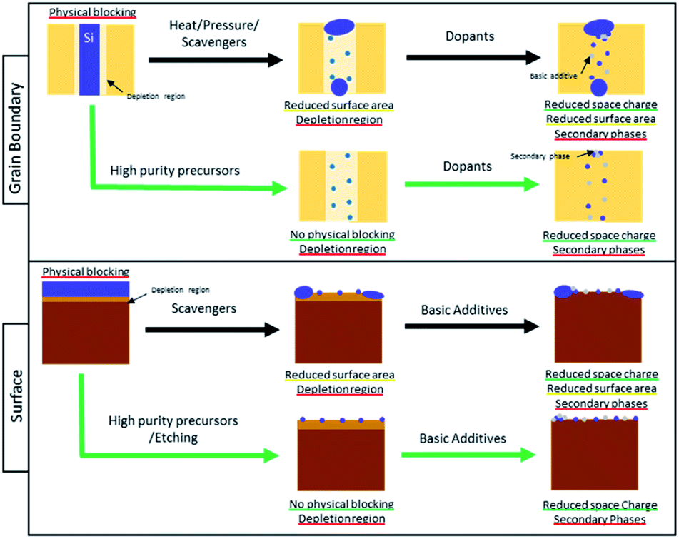 | ||
| Fig. 13 The means for addressing Si-poisoning at grain boundaries and on surfaces. Advantages of mitigation methods are underlined in green, aspects that are not entirely resolved are underlined in yellow and problems that remain or are caused are underlined in red. | ||
The conclusions of this review are summarized in Fig. 13. It is possible using, e.g. heat, pressure, and scavenging to reduce the effect of high level of Si-contamination (shown in Fig. 13 as a dense blue layer) by reducing the area that is physically blocked by the contaminant. In the case of the surface, the impurities can also be removed after preparation using e.g. etching, but this is an additional preparation step. In order to avoid any regions of physical blocking, it is therefore best to work with high purity precursors and to avoid sources of Si-contamination during sample preparation. It is however not feasible to entirely avoid contamination and at low concentrations (small blue dots in Fig. 13), Si-impurities often result in the creation of space charge regions that negatively affect the interaction of the surface with oxygen (light brown in Fig. 13) or cause high grain boundary resistance (light beige in Fig. 13). Based on recent work, it appears that space charge regions induced by acidic silica can be compensated with basic additives or dopants (small grey dots in Fig. 13).67 This method is, however, not trivial to implement as modifying surface and grain boundary composition locally is challenging. Additionally, the formation of secondary phases between the additive and the Si-impurities (clusters of grey and blue dots Fig. 13) are also possible. The effects of these secondary phases is unclear and still needs to be studied. In the future, alternative methods of modifying space charge regions without the need to modify the material chemistry would be desirable. For examples the authors have recently demonstrated,154 that it possible to use above band gap illumination to shrink the space charge potentials at grain boundaries in an acceptor doped ceria-based electrolyte thin film. In the case of the surface, similar phenomena have often been reported in photoelectrochemistry where above band gap illumination is known to modify the surface potential of metal oxides which aids in enhancing their surface reaction kinetics. This has been used in the realm of metal oxide gas sensors, for example, to operate cells at reduced temperature.155 An additional benefit of light in this case is that it also improves the sensing response by facilitating the desorption of analytes, thus enabling operation of devices near room temperature. Overall, this could create new opportunities to modify space charge potential at interfaces in metal oxide without the need to modify the materials chemistry and as such may be a valuable tool.
Conflicts of interest
NoneAcknowledgements
A. Staerz, H. G. Seo, and H. L. Tuller thank the the US Department of Energy (DOE), National Energy Technology Laboratory (NETL), Office of Fossil Energy under award no. DE-FE0031668—Robust highly durable solid oxide fuel cell cathodes – Improved materials compatibility & self-regulating surface chemistry for their support related to surface poisoning effects, and T. Defferriere, and H. L. Tuller from the Department of Energy, Basic Energy Sciences under award number DE-SC0002633 (Chemomechanics of Far-From-Equilibrium Interfaces) for support for their research related to the investigation of space charge effects at solid electrolyte grain boundaries. The authors thank Martijn Van essen, from Det Norske Veritas, Groningen, The Netherlands for providing the photograph of a poisoned lambda probe.Notes and references
- P. V. Kamat, J. Phys. Chem. Lett., 2011, 2, 839–840 CrossRef CAS.
- D. Rüffer, F. Hoehne and J. Bühler, Sensors, 2018, 18, 1052 CrossRef PubMed.
- D. Kuhlgatz, Sensing the Adequate Mixture-The Bosch Lambda Sensors, accessed 31 July 2021, https://www.bosch.com/stories/40-years-of-bosch-lambda-sensor/ Search PubMed.
- N. Taguchi, US Pat., 3631436, 1971 Search PubMed.
- G. Neri, Chemosensors, 2015, 3, 1–20 CrossRef CAS.
- M. Blaschke, T. Tille, P. Robertson, S. Mair, U. Weimar and H. Ulmer, IEEE Sens. J., 2006, 6, 1–12 Search PubMed.
- T. Tille, Procedia Eng., 2010, 5, 5–8 CrossRef CAS.
- L. Wood, Global Indoor Air Aulita Monitor Market Analysis, Trends and Forecasts 2019-2025, accessed 14 September 2021, https://www.businesswire.com/news/home/20200310005492/en/Global-Indoor-Air-Quality-Monitor-Market-Analysis-Trends-and-Forecasts-2019-2025---ResearchAndMarkets.com Search PubMed.
- F. Haber and A. Moser, Z. Elektrotech. Elektrochem., 1905, 264, 593–609 CrossRef.
- Bloom Energy powers two California sites in fast pandemic response, Fuel Cells Bull., 2020, 5, 6–7, ISSN 1464-2859, DOI:10.1016/S1464-2859(20)30191-7, https://www.sciencedirect.com/science/article/pii/S1464285920301917.
- R. Miller, Bloom's Breakthrough Moment? Equinix to Install 40 MW of Fuel Cells, accessed 14 September 2021, https://datacenterfrontier.com/blooms-breakthrough-moment-equinix-orders-40-mw-of-fuel-cells/ Search PubMed.
- R. Miller, Solid Oxide Fuel Cell Market to Hit USD 5.31 Billion in 2028; Increasing Need to Reduce Carbon Emissions and High Energy Demand to Boost Growth: Fortune Business Insights, accessed 14 September 2021, https://www.globenewswire.com/news-release/2021/08/06/2276195/0/en/Solid-Oxide-Fuel-Cell-Market-to-Hit-USD-5-31-Billion-in-2028-Increasing-Need-to-Reduce-Carbon-Emissions-and-High-Energy-Demand-to-Boost-Growth-Fortune-Business-Insights.html Search PubMed.
- K. Izawa, H. Ulmer, A. Staerz, U. Weimar and N. Barsan, in Gas Sensors Based on Conducting Metal Oxides: Basics Understanding, Technology and Applications, ed. N. Barsan and K. Schierbaum, Elsevier, 2018, pp. 217–251 Search PubMed.
- L. Wood, Solid Oxide Fuel Cells, accessed 14 September 2021, https://www.energy.gov/fe/science-innovation/clean-coal-research/solid-oxide-fuel-cells Search PubMed.
- M. Reticcioli, U. Diebold, G. Kresse and C. Franchini, in Handbook of Materials Modeling, 1985, pp. 408–418 Search PubMed.
- H. L. Tuller and A. S. Nowick, J. Phys. Chem. Solids, 1977, 38, 859–867 CrossRef CAS.
- T. Seiyama, A. Kato, K. Fujishi and M. Nagatani, Anal. Chem., 1962, 34, 1502–1503 CrossRef CAS.
- M. A. Han, H. J. Kim, H. C. Lee, J. S. Park and H. N. Lee, Appl. Surf. Sci., 2019, 481, 133–137 CrossRef CAS.
- N. Barsan, U. Weimar and M. Hübner, in Semiconductor Gas Sensors, Woodhead Publishing Limited, 2013, pp. 35–63 Search PubMed.
- N. Barsan, M. Schweizer-Berberich and W. Göpel, Fresenius. J. Anal. Chem., 1999, 365, 287–304 CrossRef CAS.
- D. Kohl, Sensor. Actuator., 1989, 18, 71–113 CrossRef CAS.
- J. Maier and W. Göpel, J. Solid State Chem., 1988, 302, 293–302 CrossRef.
- N. Yamazoe, J. Fuchigami, M. Kishikawa and T. Seiyama, Surf. Sci., 1979, 86, 335–344 CrossRef CAS.
- H.-J. Kim and J.-H. Lee, Sens. Actuators, B, 2014, 192, 607–627 CrossRef CAS.
- J. Wahl, P. J. Schmidt and R. Zechmall, US Pat., 4040394, 1977 Search PubMed.
- J. Riegel, H. Neumann and H. M. Wiedenmann, Solid State Ionics, 2002, 152–153, 783–800 CrossRef CAS.
- W. Nernst, Z. Elektrochem. Angew. Phys. Chem., 1888, 2, 613–637 Search PubMed.
- R. Ramamoorthy, P. K. Dutta and S. A. Akbar, J. Mater. Sci., 2003, 38, 4271–4282 CrossRef CAS.
- M. Gödickemeiei, B. Michel, A. Orliukas, P. Bohac, K. Sasaki, L. Gauckler, H. Heinrich, P. Schwander, G. Kostorz, H. Hofmann and O. Frei, J. Mater. Res., 1994, 9, 1228–1240 CrossRef.
- S. M. Haile, Acta Mater., 2003, 51, 5981–6000 CrossRef CAS.
- M. Riazata, M. Baniassadia, M. Mazrouiea, M. Tafazolic and M. M. Zand, Energy Equip. Syst., 2015, 3, 25–32 Search PubMed.
- J. Santos and T. Matencio, in Advances in Ceramics - Synthesis and Characterization, Processing and Specific Applications, 2011, vol. 45, pp. 1548–1554 Search PubMed.
- J. Nielsen and J. Hjelm, Electrochim. Acta, 2014, 115, 31–45 CrossRef CAS.
- E. Bucher, C. Gspan, F. Hofer and W. Sitte, Solid State Ionics, 2013, 230, 7–11 CrossRef CAS.
- H. G. Seo, Y. Choi and W. C. Jung, Adv. Energy Mater., 2018, 8, 1–7 Search PubMed.
- C. Song, S. Lee, B. I. Gu, G. Y. Chang Cho, J. D. Baek and S. W. Cha, Energies, 2020, 13, 1621 CrossRef CAS.
- E. Baur and H. Preis, Z. Elektrotech. Elektrochem., 1937, 43, 727 CAS.
- H.-H. Möbius, J. Solid State Electrochem., 1997, 1, 2–16 CrossRef.
- S. J. Skinner and J. A. Kilner, Rev. Lat. Am. Lit. Arts, 2003, 6, 30–37 CAS.
- C. H. Chen, H. J. M. Bouwmeester, R. H. E. Van Doom, H. Kruidhof and A. J. Burggraaf, Solid State Ionics, 1997, 98, 7–13 CrossRef CAS.
- X. Zhu and W. Yang, Adv. Mater., 2019, 31, 1–21 Search PubMed.
- R. A. De Souza, Adv. Funct. Mater., 2015, 25, 6326–6342 CrossRef CAS.
- N. Beekmans and L. Heyne, Electrochim. Acta, 1976, 21, 303–310 CrossRef CAS.
- M. J. Verkerk, B. J. Middelhuis and A. J. Burggraaf, Solid State Ionics, 1982, 6, 159–170 CrossRef CAS.
- T. van Dijk and A. J. Burggraaf, Phys. Status Solidi, 1981, 229, 229–240 CrossRef.
- X. Guo and R. Waser, Prog. Mater. Sci., 2006, 51(2), 151–210 CrossRef CAS.
- H. L. Tuller, Solid State Ionics, 2000, 131, 143–157 CrossRef CAS.
- Y. Dong, Z. Zhang, A. Alvarez and I. W. Chen, Acta Mater., 2020, 199, 264–277 CrossRef CAS.
- N. Barsan, D. Koziej and U. Weimar, Sens. Actuators, B, 2007, 121, 18–35 CrossRef CAS.
- A. Vergara, E. Llobet, E. Martinelli, C. Di, A. D. Amico and X. Correig, Sens. Actuators, B, 2007, 122(1), 219–226 CrossRef CAS.
- M. Schüler, T. Sauerwald and A. Schütze, J. Sens., 2015, 4, 305–311 Search PubMed.
- D. Chen, A. Groß, D. C. Bono, J. Kita, R. Moos and H. L. Tuller, Solid State Ionics, 2014, 262, 914–917 CrossRef CAS.
- F. Ciucci, Solid State Ionics, 2013, 239, 28–40 CrossRef CAS.
- F. He, Y. Jiang, C. Ren, G. Dong, Y. Gan, M. jin Lee, R. D. Green and X. Xue, Solid State Ionics, 2016, 297, 82–92 CrossRef CAS.
- M. van Essen, P. Visser, S. Gersen and H. Levinsky, SAE Int. J. Fuels Lubr., 2018, 11, 35–42 CrossRef CAS.
- M. M. Viitanen, R. G. V. Welzenis, H. H. Brongersma and F. P. F. Van Berkel, Solid State Ionics, 2002, 150, 223–228 CrossRef CAS.
- A. Hauch, S. H. Jensen, J. B. Bilde-Sorensen and M. Mogensen, J. Electrochem. Soc., 2007, 154, A619 CrossRef CAS.
- N. Q. Minh, in High-Temperature Solid Oxide Fuel Cells for the 21st Century, 2016, pp. 255–282 Search PubMed.
- J. Matsuda, T. Kawasaki and S. Futamura, Microscopy, 2018, 67(5), 251–258 CrossRef CAS PubMed.
- A. Staerz, M. Bahri, U. Geyik, H. Brinkmann, U. Weimar, O. Ersen and N. Barsan, J. Phys. Chem. Lett., 2020, 11, 166–171 CrossRef CAS PubMed.
- J. An, Y. B. Kim, H. J. Jung, J. S. Park, S. W. Cha, T. M. Gür and F. B. Prinz, Int. J. Precis. Eng. Manuf., 2012, 13, 1273–1279 CrossRef.
- A. Soldati, A. Montenegro-Hernandez, L. Baque, H. Troiani, L. Mogni, A Schreiber and A. Serquis, Pract. Metallogr., 2014, 51(9), 675–688 CrossRef CAS.
- M. Batzill and U. Diebold, Phys. Chem. Chem. Phys., 2007, 9, 2307–2318 RSC.
- M. Wagner, P. Lackner, S. Seiler, A. Brunsch, R. Bliem, S. Gerhold, Z. Wang, J. Osiecki, K. Schulte, L. A. Boatner, M. Schmid, B. Meyer and U. Diebold, ACS Nano, 2017, 11, 11531–11541 CrossRef CAS PubMed.
- M. Batzill, K. Katsiev, J. M. Burst, U. Diebold, A. M. Chaka and B. Delley, Phys. Rev. B: Condens. Matter Mater. Phys., 2005, 2, 1–20 Search PubMed.
- A. Wang and T. Y. Chien, Phys. Lett. A, 2018, 382, 739–748 CrossRef CAS.
- X. Xu, Y. Liu, J. Wang, D. Isheim, V. P. Dravid, C. Phatak and S. M. Haile, Nat. Mater., 2020, 19, 887–893 CrossRef CAS PubMed.
- B. Gault, A. Chiaramonti, O. Cojocaru-Mirédin, P. Stender, R. Dubosq, C. Freysoldt, S. K. Makineni, T. Li, M. Moody and J. M. Cairney, Nat. Rev. Methods Primers, 2021, 1, 51 CrossRef.
- R. A. De Souza and M. Martin, MRS Bull., 2009, 34, 907–914 CrossRef CAS.
- E. Ciftyürek, B. Šmíd, Z. Li, V. Matolín and K. Schierbaum, Sensors, 2019, 19, 4737 CrossRef PubMed.
- F. A. Stevie, R. Garcia, J. Shallenberger, J. G. Newman and C. L. Donley, J. Vac. Sci. Technol. A: Vac. Surf. Films, 2020, 38, 063202 CrossRef CAS.
- A. Stangl, D. Muñoz-Rojas and M. Burriel, J. Phys. energy, 2021, 3, 012001 CrossRef CAS.
- D. Degler, Sensors, 2018, 18, 3544 CrossRef PubMed.
- M. Liu, M. E. Lynch, K. Blinn, F. M. Alamgir and Y. Choi, Mater. Today, 2011, 14, 534–546 CrossRef CAS.
- D. Degler, S. A. Müller, D. E. Doronkin, D. Wang, J.-D. Grunwaldt, U. Weimar and N. Barsan, J. Mater. Chem. A, 2018, 6, 2034–2046 RSC.
- D. Koziej, M. Hübner, N. Barsan, U. Weimar, M. Sikora and J.-D. Grunwaldt, Phys. Chem. Chem. Phys., 2009, 11, 8620 RSC.
- D. J. Cumming, C. Tumilson, S. F. R. Taylor, S. Chansai, A. V Call, J. Jacquemin, C. Hardacre and R. H. Elder, Faraday Discuss., 2015, 182, 97–111 RSC.
- D. Hauser, A. Nenning, A. K. Opitz, B. Klötzer and S. Penner, Rev. Sci. Instrum., 2020, 91, 084104 CrossRef CAS PubMed.
- S. A. Müller, D. Degler, C. Feldmann, M. Türk, R. Moos, K. Fink, F. Studt, D. Gerthsen, N. Bârsan and J. D. Grunwaldt, ChemCatChem, 2018, 10, 864–880 CrossRef.
- K. S. Blinn, X. Li, M. Liu, L. A. Bottomley and M. Liu, J. Vis. Exp., 2012, 67, e50161 Search PubMed.
- E. Roedel, A. Urakawa, S. Kureti and A. Baiker, Phys. Chem. Chem. Phys., 2008, 10, 6190–6198 RSC.
- A. Urakawa, N. Maeda and A. Baiker, Angew. Chem., Int. Ed., 2008, 47(48), 9256–9259 CrossRef CAS PubMed.
- A. K. Elger and C. Hess, Angew. Chem. Int. Ed., 2019, 58, 15057–15061 CrossRef CAS PubMed.
- S. Sänze, A. Gurlo and C. Hess, Angew. Chem., Int. Ed. Engl., 2013, 52, 3607–3610 CrossRef PubMed.
- F. Schipani, D. R. Miller, M. A. Ponce, C. M. Aldao, S. A. Akbar and P. A. Morris, Rev. Adv. Sci. Eng., 2016, 5(1), 86–105 CrossRef.
- M. De Ridder, A. G. J. Vervoort, R. G. Van Welzenis and H. H. Brongersma, Solid State Ionics, 2003, 156, 255–262 CrossRef CAS.
- J. L. Hertz, A. Rothschild and H. L. Tuller, J. Electroceramics, 2009, 22, 428–435 CrossRef CAS.
- I. Sreedhar, B. Agarwal, P. Goyal and A. Agarwal, J. Solid State Electrochem., 2020, 24, 1239–1270 CrossRef CAS.
- H. Madi, A. Lanzini, S. Diethelm, D. Papurello, J. Van Herle, M. Lualdi, J. Gutzon Larsen and M. Santarelli, J. Power Sources, 2015, 279, 460–471 CrossRef CAS.
- K. Haga, S. Adachi, Y. Shiratori, K. Itoh and K. Sasaki, Solid State Ionics, 2008,(27–32), 1427–1431 CrossRef CAS.
- L. Zhao, N. H. Perry, T. Daio, K. Sasaki and S. R. Bishop, Chem. Mater., 2015, 27, 3065–3070 CrossRef CAS.
- S. P. Jiang and X. Chen, Int. J. Hydrogen Energy, 2014, 39, 505–531 CrossRef CAS.
- Y. Horii and K. Kannan, Arch. Environ. Contam. Toxicol., 2008, 55, 701–710 CrossRef CAS PubMed.
- F. Meng and H. Wu, PLoS One, 2015, 10(8), 0135509 Search PubMed.
- D. E. Williams and K. F. E. Pratt, J. Chem. Soc. Faraday Trans., 1998, 94, 3493–3500 RSC.
- C. Schultealbert, I. Uzun, T. Baur, T. Sauerwald and A. Schütze, J. Sens., 2020, 9, 283–292 Search PubMed.
- K. Gaj, Energies, 2020, 13, 2605 CrossRef CAS.
- D. A. Philyaw, US Pat., 6365108B1, Caterpillar Inc., Peoria, IL, US, 2002 Search PubMed.
- D. P. F. De Souza and M. F. De Souza, J. Mater. Sci., 1999, 34, 4023–4030 CrossRef CAS.
- K. Keizer, M. J. Verkerk and A. J. Burggraaf, Ceram. Int., 1979, 5, 143–147 CAS.
- J.-H. Lee, J. H. Lee, Y.-S. Jung and D.-Y. Kim, J. Am. Ceram. Soc., 2003, 86, 1518–1521 CrossRef CAS.
- A. A. Sharif and M. L. Mecartney, Acta Mater., 2003, 51, 1633–1639 CrossRef CAS.
- Y.-M. Chiang, D. P. Birnie and W. D. Kingery, Physical Ceramics: Principles for Ceramic Science and Engineering, Wiley, 1996 Search PubMed.
- M. Backhaus-Ricoult and M. Trichet, Solid State Ionics, 2002, 150, 143–156 CrossRef CAS.
- A. Bernasik, K. Kowalski and A. Sadowski, J. Phys. Chem. Solids, 2002, 63(2), 233–239 CrossRef CAS.
- M. Aoki, Y. M. Chiang, I. Kosacki, L. J. R. Lee, H. Tuller and Y. Liu, J. Am. Ceram. Soc., 1996, 79, 1169–1180 CrossRef CAS.
- S. P. S. Badwal, F. Ciacchi, M. V. Swain and V. Zelizko, J. Am. Ceram. Soc., 1990, 73(8), 2505–2507 CrossRef CAS.
- M. Kleitz, L. Dessemond and M. C. Steil, Solid State Ionics, 1995, 75, 107–115 CrossRef CAS.
- J. Fleig and J. Maier, J. Am. Ceram. Soc., 1999, 82, 3485–3493 CrossRef CAS.
- S. P. S. Badwal and A. E. Hughes, J. Eur. Ceram. Soc., 1992, 10, 115–122 CrossRef CAS.
- T. S. Zhang, J. Ma, S. H. Chan, P. Hing and J. A. Kilner, Solid State Sci., 2004, 6(6), 565–572 CrossRef CAS.
- X. Guo and J. Maier, J. Electrochem. Soc., 2001, 148, E121–E126 CrossRef CAS.
- R. Kirchheim, Acta Mater., 2007, 55, 5129–5138 CrossRef CAS.
- B. W. Holleboom, S. W. Hawes and E. L. Ker, SAE Technical Paper 860478, 1986 Search PubMed.
- G. Tournier and C. Pijolat, Sens. Actuators, B, 2005, 106(2), 553–562 CrossRef CAS.
- A. Cabot, J. Arbiol, A. Cornet, J. R. Morante, F. Chen and M. Liu, Thin Solid Films, 2003, 436, 64–69 CrossRef CAS.
- J. Van Den Broek, I. C. Weber, A. T. Guentner and S. E. Pratsinis, Mater. Horiz., 2021, 8, 661–684 RSC.
- X. Meng, Q. Zhang, S. Zhang and Z. He, Sensors, 2019, 19, 2478 CrossRef CAS PubMed.
- A. Katsuki and K. Fukui, Sens. Actuators, B, 1998, 52, 30–37 CrossRef CAS.
- K. Wada and M. Egashira, Sens. Actuators, B, 1998, 53, 147–154 CrossRef CAS.
- M. Perz, E. Bucher, C. Gspan, J. Waldhäusl, F. Hofer and W. Sitte, Solid State Ionics, 2016, 288, 22–27 CrossRef CAS.
- E. Bucher, W. Sitte, F. Klauser and E. Bertel, Solid State Ionics, 2011, 191, 61–67 CrossRef CAS.
- Y. Liu, X. Zhu, M. Li, W. Li and W. Yang, Mater. Horiz., 2015, 492, 173–180 CAS.
- A. K. Opitz, M. P. Hörlein, T. Huber and J. Fleig, J. Electrochem. Soc., 2012, 159, B502–B513 CrossRef CAS.
- A. K. Opitz, A. Lutz, M. Kubicek, F. Kubel, H. Hutter and J. Fleig, Electrochim. Acta, 2011, 56, 9727–9740 CrossRef CAS PubMed.
- M. Mogensen, K. V. Jensen, M. J. Jorgensen and S. Primdahl, Solid State Ionics, 2002, 150, 123–129 CrossRef CAS.
- E. Mutoro, N. Baumann and J. Janek, J. Phys. Chem. Lett., 2010, 1, 2322–2326 CrossRef CAS.
- E. Mutoro, B. Luerßen, S. Günther and J. Janek, Solid State Ionics, 2009, 180, 1019–1033 CrossRef CAS.
- N. Yamazoe, Y. Kurokawa and T. Seiyama, Sens. Actuators, B, 1983, 4, 283–289 CrossRef CAS.
- S. R. Morrison, Sens. Actuators, B, 1987, 12, 425–440 CrossRef CAS.
- N. Yamazoe, Sens. Actuators, B, 1991, 5, 7–19 CrossRef CAS.
- C. Nicollet, C. Toparli, G. F. Harrington, T. Defferriere, B. Yildiz and H. L. Tuller, Nat. Catal., 2020, 3, 913–920 CrossRef CAS.
- D. W. Smith, J. Chem. Educ., 1987, 64, 480–481 CrossRef CAS.
- Y. Ma and J. D. Nicholas, J. Electrochem. Soc., 2021, 168, 104518 CrossRef CAS.
- A. Marikutsa, M. Rumyantseva, E. A. Konstantinova and A. Gaskov, Sensors, 2021, 21, 2554 CrossRef CAS PubMed.
- J. Lee, T. Mori, J. Li, T. Ikegami, M. Komatsu and H. Haneda, J. Electrochem. Soc., 2000, 147, 2822 CrossRef CAS.
- J.-H. Lee, T. Mori, J.-G. Li, T. Ikegami, J. Drennan and D.-Y. Kim, J. Mater. Res., 2001, 168(16), 2377–2383 CrossRef.
- S. Rajendran, J. Drennan and S. P. S. Badwal, J. Mater. Sci. Lett., 1987, 6, 1431–1434 CrossRef CAS.
- T. S. Zhang, J. Ma, Y. J. Leng, S. H. Chan, P. Hing and J. A. Kilner, Solid State Ionics, 2004, 168(1–2), 187–195 CrossRef CAS.
- M. J. Verkerk, A. J. A. Winnubst and A. J. Burggraaf, J. Mater. Sci., 1982, 17, 3113–3122 CrossRef CAS.
- Y. H. Cho, P. S. Cho, G. Auchterlonie, D. K. Kim, J. H. Lee, D. Y. Kim, H. M. Park and J. Drennan, Acta Mater., 2007, 55, 4807–4815 CrossRef CAS.
- J.-H. Lee, Monatsh. Chem., 2009, 140, 1081–1094 CrossRef CAS.
- J. H. Lee, T. Mori, J. G. Li, T. Ikegami, M. Komatsu and H. Haneda, Electrochemistry, 2000, 68, 427–432 CrossRef CAS.
- A. Nenning and A. Opitz, JPhys Energy, 2019, 2, 014002 CrossRef.
- J. Koettgen, S. Grieshammer, P. Hein, B. O. H. Grope, M. Nakayama and M. Martin, Phys. Chem. Chem. Phys., 2018, 20, 14291–14321 RSC.
- L. Ge, Q. Ni, G. Cai, T. Sang and L. Guo, J. Power Sources, 2016, 324, 582–588 CrossRef CAS.
- P. S. Cho, S. B. Lee, Y. H. Cho, D. Y. Kim, H. M. Park and J. H. Lee, J. Power Sources, 2008, 183, 518–523 CrossRef CAS.
- J. A. Lane, J. L. Neff and G. M. Christie, Solid State Ionics, 2006, 177(19–25), 1911–1915 CrossRef CAS.
- D. K. Kim, P.-S. Cho, J.-H. Lee, D.-Y. Kim, H.-M. Park, G. Auchterlonie and J. Drennan, Electrochem. Solid-State Lett., 2007, 10, B91 CrossRef CAS.
- S. J. Litzelman, R. A. De Souza, B. Butz, H. L. Tuller, M. Martin and D. Gerthsen, J. Electroceramics, 2009, 22, 405–415 CrossRef CAS.
- H. J. Avila-Paredes and S. Kim, Solid State Ionics, 2006, 177, 3075–3080 CrossRef CAS.
- Y. Tao, J. Shao and S. Cheng, ACS Appl. Mater. Interfaces, 2016, 8, 17023–17027 CrossRef CAS PubMed.
- S. R. Bishop, J. Druce, J. A. Kilner, T. Ishihara and K. Sasaki, ECS Trans., 2013, 57, 2003–2007 CrossRef.
- T. Defferriere, D. Klotz, J. C. Gonzalez-Rosillo, J. L. M. Rupp and H. L. Tuller, Photo-enhanced ionic conductivity across grain boundaries in polycrystaline ceramics, Nat. Mater Search PubMed in press.
- F. Xu and H. P. Ho, Micromachines, 2017, 8, 333 CrossRef PubMed.
Footnote |
| † These authors contributed equally. |
| This journal is © The Royal Society of Chemistry 2022 |