
Self-driven dual hydrogen production system based on a bifunctional single-atomic Rh catalyst†
Xianyun
Peng
ab,
Yuying
Mi
b,
Xijun
Liu
 *c,
Jiaqiang
Sun
d,
Yuan
Qiu
b,
Shusheng
Zhang
e,
Xiaoxing
Ke
f,
Xinzhong
Wang
*a and
Jun
Luo
*b
*c,
Jiaqiang
Sun
d,
Yuan
Qiu
b,
Shusheng
Zhang
e,
Xiaoxing
Ke
f,
Xinzhong
Wang
*a and
Jun
Luo
*b
aInformation Technology Research Institute, Shenzhen Institute of Information Technology, Shenzhen 518172, China. E-mail: wangxz@sziit.com.cn
bInstitute for New Energy Materials & Low-Carbon Technologies, Tianjin Key Lab for Photoelectric Materials & Devices, School of Materials Science and Engineering, Tianjin University of Technology, Tianjin 300384, China. E-mail: jluo@email.tjut.edu.cn
cMOE Key Laboratory of New Processing Technology for Non-Ferrous Metals and Materials, Guangxi Key Laboratory of Processing for Non-Ferrous Metals and Featured Materials, School of Physical Science and Technology, Guangxi University, Nanning 530004, China. E-mail: xjliu@tjut.edu.cn
dState Key Laboratory of Coal Conversion, Institute of Coal Chemistry, Chinese Academy of Sciences, Taiyuan 030001, China
eCollege of Chemistry, Zhengzhou University, Zhengzhou 450000, China
fBeijing Key Laboratory of Microstructure and Properties of Solids, Faculty of Materials and Manufacturing, Beijing University of Technology, Beijing 100124, China
First published on 6th November 2021
Abstract
Electrocatalytic hydrogen evolution is an efficient and economical technology to address environmental contamination and energy crises, but the development of such a high-efficiency and energy-saving sustainable hydrogen production system remains a great challenge. Here, we present a novel strategy to design a self-driven dual hydrogen production system for efficient hydrogen production based on highly-dispersed single Rh atoms supported on an oxygen-functionalized Ti3C2Ox MXene (Rh-SA/Ti3C2Ox) catalyst. The bifunctional Rh-SA/Ti3C2Ox catalyst exhibits remarkable catalytic activities towards both the pH-universal hydrogen evolution reaction (HER) and hydrazine oxidation reaction (HzOR). Using Rh-SA/Ti3C2Ox as the electrode in the self-driven dual hydrogen production system by combining a Zn–H2 battery and overall hydrazine splitting units, an ultra-high H2 generation rate of 45.77 mmol h−1 can be achieved. Density functional theory calculations indicate that the atomically dispersed single Rh atoms not only make the free energy of adsorbed H (ΔG*H) more thermoneutral for the HER but also largely decrease the free-energy barrier of the dehydrogenation of adsorbed NHNH2 for the HzOR.
Introduction
Rapidly increasing energy consumption and the concerns over the deteriorating global environmental situation have driven the demand for clean and sustainable energy sources. Hydrogen (H2), an energy carrier with a high energy density and zero carbon emissions, has attracted growing attention as a vital fascinating candidate for preventing global warming and environmental crisis.1–4 The development of H2 production approaches has become a research hotspot in recent years. Among the strategies that have been developed to date, electrocatalytic overall water/hydrazine splitting (OWS/OHZS), involving the hydrogen evolution reaction (HER) and water/hydrazine evolution reaction (OER/HzOR), is deemed as a suitable and green process, and has thus received much attention.5–8Despite the electrocatalytic OWS and OHzS for hydrogen production having been well developed to date, they are commonly driven by outsourcing electricity directly, which conflicts with sustainable development goals. Numerous efforts have been devoted to generating H2 by fabricating clean and efficient self-driven H2 production systems using integrated energy storage devices, such as solar energy, rechargeable Zn–air batteries, and direct hydrazine fuel cells.9–13 However, these strategies are all limited to a single compartment with a cathode for catalyzing the HER with a relatively low H2 production rate. Besides this, it should be noted that the H2 production rate in the OWS unit is largely restricted by the sluggish kinetics of the anodic OER involving a four-electron-transfer process, compared with those of the OHzS process.2,14–16 A further improvement in the production rate by constructing an advanced self-driven system is more preferential for commercial applications, but also extremely challenging.
Inspired by these pioneering advancements, herein we demonstrate for the first time a self-driven dual hydrogen production system by the introduction of a Zn–H2 battery. The Zn–H2 battery can not only produce H2, but can also generate electricity. Thermodynamically, the reduction potential of the H+/H2 redox couple on the cathode and the one of the Zn2+/Zn couple on the anode are 0 and −1.25 V versus the standard hydrogen electrode (vs. SHE), respectively. For the Zn–H2 battery, the theoretical cathode potential (Ec) and theoretical anode potential (Ea) can be calculated as 0.035 V and −1.285 V, respectively. Thus, the theoretical electromotive force (Eemf = Ec − Ea) of the battery can be confirmed as 1.32 V. However, it is hard for the voltage to drive the OWS due to the sluggish kinetics and high theoretical thermodynamic potential of the anodic OER of 1.23 V versus the reversible hydrogen electrode (vs. RHE).17–20 Fortunately, replacing the OER with the HzOR and forming an OHzS system can sharply decrease the operating voltage due to its unique feature of the ultra-low theoretical oxidation potential of −0.33 V vs. RHE.21–24 Therefore, a self-driven dual hydrogen production system can be constructed by combining a Zn–H2 battery and OHzS, which can generate hydrogen efficiently on two cathodes (the Zn–H2 battery and OHzS electrolytic cell) simultaneously with high energy efficiency.
To realize such a concept system, the cathode must be highly active toward both the HER and OHzS. However, the state-of-art platinum (Pt) catalyst is expensive and exhibits low metal atom utilization. Recently, single-atom catalysts (SAs) have been shown to exhibit extraordinary HER activity benefitting from maximum metal atom utilization, low coordination, and good reactivity. Therefore, downsizing nanocatalysts to atomically dispersed atoms is an effective strategy to achieve a comparable HER performance to that of the commercial Pt/C catalyst and greatly reduce the costs of catalysts containing noble metals by reducing the loading of noble metals. Here, a single atom Rh immobilized Ti3C2Ox MXene (Rh-SA/Ti3C2Ox) catalyst was applied considering that Rh-based nanomaterials not only have excellent Pt-like catalytic performance for the HER,25,26 but also excellent HzOR catalytic activity.27 Electrochemical measurements confirmed that Rh-SA/Ti3C2Ox exhibits superior electrocatalytic activities toward both the pH-universal HER and HzOR. Benefiting from the good electrochemical performances of the designed catalyst, an asymmetric alkali–acid Zn–H2 battery was constructed, which exhibits a high peak power density of 110.8 mW cm−2 at 175 mA cm−2 and a large specific capacity of 802.4 mA h gZn−1 at a current density of 10 mA cm−2. More importantly, a proof-of-concept self-driven dual hydrogen production system was constructed by the combined utilization of a Zn–H2 battery to drive OHzS for H2 production. Unexpectedly, an ultra-high H2 generation rate of 45.77 mmol h−1 can be achieved under ambient conditions using the assembled self-driven dual hydrogen production system. The theoretical calculations further provide detail on the fundamental origins of the excellent HER and HzOR performances of the single-atomic Rh catalysts.
Results and discussion
Synthesis and characterization of the Rh-SA/Ti3C2Ox catalyst
The schematic for synthesizing the Rh-SA/Ti3C2Ox catalyst is illustrated in Fig. 1a. In the first step, the Rh precursor (RhCl3·xH2O) was added during the exfoliating process of Ti3C2Tx nanosheets from a MAX phase Ti3AlC2 using LiF/HCl.28,29 Then, the resulting composite was treated with KOH, which can effectively induce the production of a rapid flocculate of the Ti3C2Tx nanosheets due to the great change in pH value. More importantly, the introduced base replaces the residual –F groups with concentrated –OH in aqueous solution.30,31 Finally, the Rh-SA/Ti3C2Ox catalyst was obtained via annealing treatment of the alkalized composites under an Ar atmosphere. The Ti3C2Ox catalyst was also obtained via the same procedure as that of Rh-SA/Ti3C2Ox, except that the Rh precursor was not added (please see the Methods section for more details).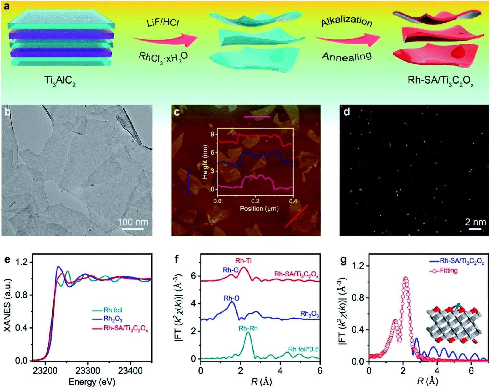 | ||
| Fig. 1 Synthesis and structural characterization of the Rh-SA/Ti3C2Ox catalyst: (a) scheme of the synthesis of Rh-SA/Ti3C2Ox; (b) AFM image, the inset shows the corresponding height profiles; (c) TEM image of Rh-SA/Ti3C2Ox; (d) aberration-corrected HAADF-STEM image; (e) Ru K-edge XANES spectra of the Rh-SA/Ti3C2Ox catalyst and Rh foil, as well as Rh2O3 references; (f) FT-EXAFS k2-weighted χ(k) function spectra of Rh-SA/Ti3C2Ox and those of reference samples; (g) the corresponding FT-EXAFS fitting curves of Rh-SA/Ti3C2Ox. | ||
The X-ray diffraction (XRD) patterns in Fig. S1† show that the dominant peaks of Rh-SA/Ti3C2Ox are the same as those of the Ti3C2Ox, in which the strong peak of the (002) plane below 10° accompanied by peaks for the (004) and (110) planes indicate the successful synthesis of Ti3C2Tx.32–35 As shown in Fig. 1b, the typical two-dimensional (2D) nanosheet morphology was confirmed from the transmission electron microscopy (TEM) image of Rh-SA/Ti3C2Ox. The clear and well-defined outline with highly transparent features indicates the ultrathin nature of the material. No obvious Rh nanoparticle formation was observed in the Rh-SA/Ti3C2Ox nanosheets. Furthermore, the lateral sizes of these 2D nanosheets are hundreds of nanometers, while the thickness of these 2D nanosheets is approximately 2 nm, as determined from the atomic force microscopy (AFM) images (Fig. 1c and S2†), consistent with the TEM analysis results and demonstrating the successful synthesis of the ultrathin Rh-SA/Ti3C2Ox nanosheets.
To verify that the Rh species in the Rh-SA/Ti3C2Ox catalyst are atomically dispersed in the nanosheets, aberration-corrected high-angle annular dark-field scanning transmission electron microscopy (HAADF-STEM) characterization was performed. The high-resolution HAADF-STEM images show that ultrasmall bright spots are uniformly distributed on the nanosheets (Fig. 1d), suggesting the presence of isolated single Rh atoms in the Rh-SA/Ti3C2Ox catalyst. Scanning transmission electron microscopy-energy dispersive X-ray (STEM-EDX) mapping shows the existence and uniform distribution of Ti, C, O, and Rh elements in the Rh-SA/Ti3C2Ox catalyst (Fig. S3†). The Rh loading was determined to be 0.17 wt% by inductively coupled plasma optical emission spectrometry (ICP-OES) analysis. N2 adsorption–desorption isotherms were recorded to investigate the surface area and porosity of the Rh-SA/Ti3C2Ox (Fig. S4†). As shown, the as-prepared Rh-SA/Ti3C2Ox catalyst shows typical hybrid-type IV isotherms with a high N2 uptake at both low and high pressures. The Rh-SA/Ti3C2Ox exhibits the highest Brunauer–Emmett–Teller (BET) surface area of 441.81 m2 g−1, with a pore volume of 0.333 cm3 g−1. This feature contributes towards the exposure of active sites and benefits rapid electrochemical reaction. Besides this, Rh-NP/Ti3C2Ox (specific surface area: 416.61 m2 g−1; pore volume: 0.397 cm3 g−1; prominent pore size: 2.5 nm) exhibits a similar pore structure and specific surface area properties to those of Rh-SA/Ti3C2Ox, which provides higher comparability for the electrochemical performance comparison of Rh-SA/Ti3C2Ox and Rh-SA/Ti3C2Ox.
To verify and explore the electronic structure and coordination environment of the isolated dispersed Rh SAs in the Rh SA/Ti3C2Ox catalyst at the atomic level, we performed X-ray absorption fine structure (XAFS) measurements at the Rh K-edge. As shown in the X-ray absorption near-edge structure (XANES) spectra (Fig. 1e), the absorption edge position of the white line for Rh-SA/Ti3C2Ox is located between those of the Rh foil and Rh2O3 (Fig. S5†), indicating that the valence state of the Rh SAs is situated between that of Rh0 and Rh3+. Fig. 1f shows the Rh Fourier-transformed extended X-ray absorption fine structure (FT-EXAFS) spectra of Rh-SA/Ti3C2Ox and the reference samples. The spectrum of Rh-SA/Ti3C2Ox exhibits two main peaks at around 1.5 and 2.2 Å, associated with the first shell of Rh–O scattering and the higher shell of Rh–Ti, respectively. Compared to the FT-EXAFS spectrum of Rh foil, no reflection from the Rh–Rh contribution is observed, which further demonstrates that the Rh species in the Rh-SA/Ti3C2Ox catalyst are atomically dispersed without aggregation.36,37 Furthermore, the coordination environment of the atomically-dispersed centers was further quantified by least-squares EXAFS curve-fitting analysis (Fig. 1g and Table S1†). As shown, the best-fitted results of the R-space spectrum for Rh-SA/Ti3C2Ox depict the proposed coordination structure of Ti–Rh–O3 with Rh–O and Rh–Ti bonds (Fig. 1g, inset).
Evaluation of the HER performance
The electrocatalytic performance of the Rh-SA/Ti3C2Ox catalyst towards the HER was examined using a typical three-electrode system in an acidic medium using Ag/AgCl as the reference electrode (the electrode was carefully calibrated to the RHE) and graphite rod as the counter electrode. The commercial Pt/C with a Pt loading of 20 wt%, Ti3C2Ox (Fig. S6†), and Rh-NP/Ti3C2Ox (Fig. S7†) were also been investigated as references. Fig. 2a shows the iR-compensated linear sweep voltammetry (LSV) curves recorded at a scan rate of 10 mV s−1 in 0.1 M H2SO4 solution. As displayed, the Rh-SA/Ti3C2Ox catalyst exhibits extraordinary catalytic activity towards the HER, with a near-zero onset potential. To rationally compare the catalytic performance, the HER catalytic activity was normalized to the “current/metal loading mass” (A mg−1). Notably, the Rh-SA/Ti3C2Ox catalyst exhibits much higher HER catalytic activity than Rh-NP/Ti3C2Ox and even surpasses the performance of the commercial Pt/C catalyst (Fig. 2b) and the majority of the reported HER electrocatalysts (Table S2†). In detail, Rh-SA/Ti3C2Ox exhibits an overpotential (η) of 23 mV at a current density of −10 mA cm−2 (Fig. 2c), 65 mV lower than that of Rh-NP/Ti3C2Ox (88 mV) and 50 mV lower than that of commercial Pt/C (73 mV), indicating the superior catalytic activity of Rh-SA/Ti3C2Ox in acidic media. Also, Rh-SA/Ti3C2Ox exhibits excellent HER performance at high current densities, as shown in Fig. 2c. Moreover, the mass activities for Rh-SA/Ti3C2Ox, Rh-NP/Ti3C2Ox, and commercial Pt/C at an overpotential of 0.1 V are −141.58, −0.57, and −2.72 A mg−1, respectively, where Rh-SA/Ti3C2Ox is 248.4 and 52.1 times more active than the Rh-NP/Ti3C2Ox and Pt/C catalysts, respectively.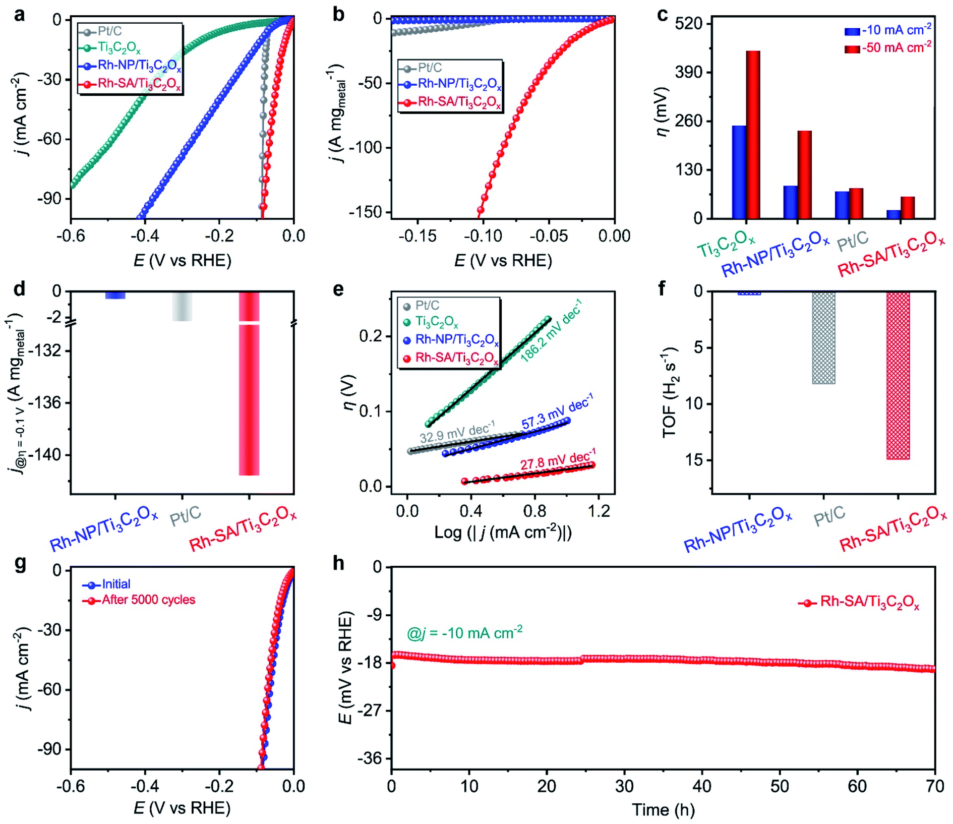 | ||
| Fig. 2 The HER electrochemical performances of the as-prepared catalysts measured under acidic conditions: (a) the geometric-area-normalized HER polarization curves of Ti3C2Ox, Rh-NP/Ti3C2Ox, Rh-SA/Ti3C2Ox, and commercial Pt/C catalysts in 0.1 M H2SO4 solution, at a scan rate of 10 mV s−1; (b) the corresponding mass-normalized HER polarization curves; (c) the overpotentials at current densities of −10 and −50 mA cm−2; (d) the HER mass activity at η = −0.1 V vs. RHE; (e) Tafel plots; (f) TOF values at η = −0.1 V vs. RHE; (g) polarization curves of the Rh-SA/Ti3C2Ox initially and after 5000 cycles; (h) stability testing of Rh-SA/Ti3C2Ox for the HER at j = −10 mA cm−2. | ||
The rapid rise in current density is also reflected in the dynamic process using Tafel plots, which provide profound insights into the fundamental HER kinetic mechanism that occurs on the surfaces of the electrocatalysts.38–41 As a result of the low energy barrier (0.44 eV on Pt) of the Volmer step, the kinetic rate-limiting step for the Pt catalyst is the Tafel process, and the theoretical Tafel slope is 30 mV dec−1 (here the Tafel slope of the commercial Pt catalyst was measured to be 32.9 mV dec−1).38,42 Remarkably, the Tafel slope of the Rh-SA/Ti3C2Ox catalyst is as low as 27.8 mV dec−1, which is far lower than the values of 57.3 mV dec−1 for Rh-NP/Ti3C2Ox and 186.2 mV dec−1 for Ti3C2Ox, and highly comparable to those of previously reported electrocatalysts (Table S2†). These results indicate that the electrocatalytic HER kinetics on the Rh-SA/Ti3C2Ox electrocatalyst are determined by the Tafel step rather than a coupled Volmer–Tafel or Volmer–Heyrovsky process. In other words, the prior Volmer step is significantly accelerated. By extrapolating the Tafel plots to a value of the potential of 0 V, the exchange current density (j0) was determined, which can be applied to assess the kinetic HER activity. As shown in Fig. S8,† the j0 value of the Rh-SA/Ti3C2Ox catalyst is 1.57 mA cm−2, which is much higher than that of Rh-NP/Ti3C2Ox (0.33 mA cm−2) and those of most previously reported HER electrocatalysts (Table S3†), suggesting a more rapid HER rate and an additional kinetic advantage for Rh-SA/Ti3C2Ox.43–46 Moreover, compared with Rh-NP/Ti3C2Ox, the HER process of Rh-SA/Ti3C2Ox is favorable, confirming that the enhanced atomic efficiency of the Rh SAs could effectively boost the catalytic activity, even at an extremely low Rh loading. We ascribe this remarkably enhanced HER catalytic activity to the associated interactions between the Ti3C2Ox substrate and the individual Rh SAs.
Turnover frequency (TOF), which is related to the number of H2 molecules evolved per second per active site, is the most important figure of merit to use to gain insight into the intrinsic activity of an electrocatalyst.47–50 Impressively, the TOF number of Rh-SA/Ti3C2Ox is 14.9 H2 s−1 at an overpotential of −0.1 V vs. RHE (Fig. 2f and S9†), which is around 49.7 and 1.8 times greater than those of Rh-NP/Ti3C2Ox (0.3 H2 s−1) and commercial Pt/C (8.2 H2 s−1), respectively. To gain further insight into the high activity of the Rh-SA/Ti3C2Ox catalyst, electrochemical impedance spectroscopy (EIS) and electrochemical active surface area (ECSA) measurements were carried out. As shown in Fig. S10,† the Nyquist plots reveal that Rh-SA/Ti3C2Ox exhibits an enhanced electron transfer rate and fast catalytic kinetics, thus leading to excellent electrochemical activity.51 The value of the double layer capacitance (Cdl) values of the catalysts were measured to estimate the ECSAs by recording cyclic voltammetry (CV) cycles at different scan rates (Fig. S11a–c†).52–55 As displayed in Fig. S11d,† the Cdl of the Rh-SA/Ti3C2Ox catalyst is 101.6 mF cm−2, which is 7.0 and 1.9 times greater than those of Ti3C2Ox (14.5 mF cm−1) and Rh-NP/Ti3C2Ox (52.2 mF cm−1), respectively. This implies that Rh-SA/Ti3C2Ox has a higher surface area and more exposed active sites than the other catalysts, which are beneficial to enhancing its HER activity. These results are in good agreement with the trends in the Tafel slopes, which further confirms the superiority of the Rh-SA/Ti3C2Ox catalyst. Moreover, as the surface topology can affect catalyst performance, the ECSA-normalized current density was also measured to determine the intrinsic HER activity of the catalyst. From the normalization of the current density curves by the ECSA (Fig. S12†), it can be seen that the Rh-SA/Ti3C2Ox catalyst has a non-dominant activity due to its high Cdl value.
Apart from superior electrocatalytic activities, we further examined the long-term stability of Rh-SA/Ti3C2Ox for practical applications. As shown in Fig. 2g, continuous CV cycling tests of the Rh-SA/Ti3C2Ox were conducted over 5000 cycles. After the cycling tests, the polarization curve revealed no variation in current density from that recorded initially. In addition, chronoamperometric testing performed at a constant overpotential showed almost no decrease in current density over 70 h (Fig. 2h), confirming the reliable stability of Rh-SA/Ti3C2Ox. No clusters and particles could be observed on the surface of the Rh-SA/Ti3C2Ox nanosheets after the stability testing (Fig. S13†), confirming its robust structural stability during the HER process.
The HER electrochemical performances of Rh-SA/Ti3C2Ox were also studied under alkaline and neutral conditions. Fig. 3a shows the LSV curves of the as-prepared catalysts in 0.1 M KOH electrolyte. Notably, the Rh-SA/Ti3C2Ox catalyst exhibits excellent performance, with an overpotential of 29 mV to achieve a current density of −10 mA cm−2, surpassing that of Pt/C (47 mV) and most previously synthesized HER electrocatalysts under alkaline conditions (Table S4†), much higher than those of Ti3C2Ox (146 mV) and Rh-SA/Ti3C2Ox (97 mV) (Fig. 3b). Meanwhile, Rh-SA/Ti3C2Ox also presents excellent HER performance at high current densities in alkaline solution, as shown in Fig. 3b. Fig. 3c shows that Rh-SA/Ti3C2Ox exhibits the fastest dynamics, with a Tafel slope of 47.6 mV dec−1, surpassing the performance of Pt/C of 56.6 mV dec−1, and much faster than those of Ti3C2Ox (95.5 mV dec−1) and Rh-SA/Ti3C2Ox (73.4 mV dec−1).
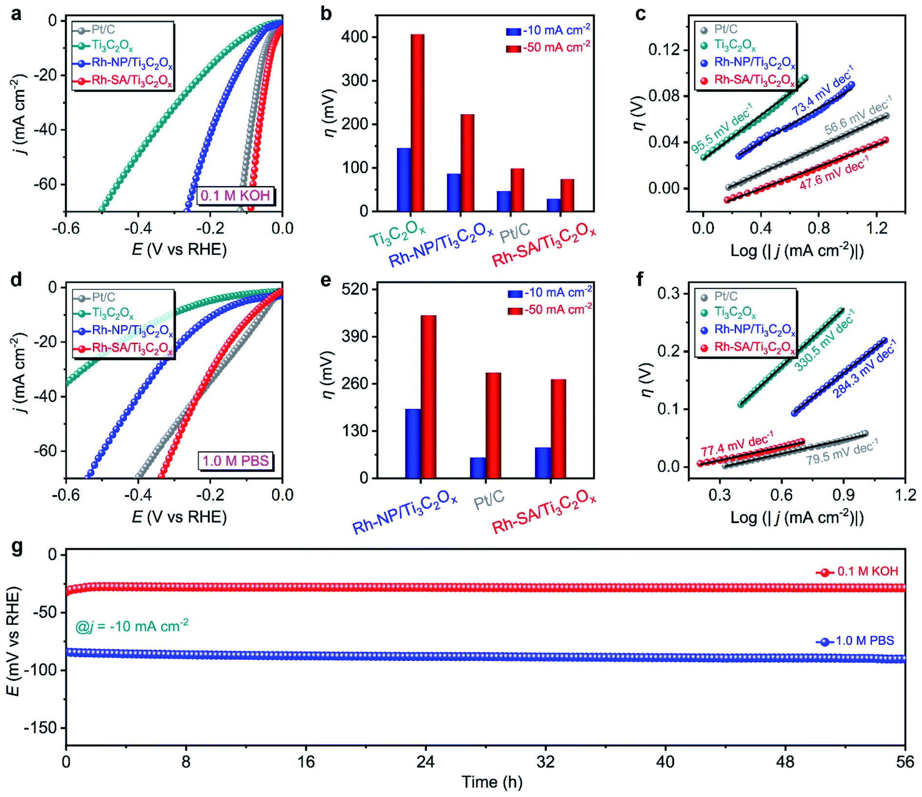 | ||
| Fig. 3 HER electrochemical performances of the as-prepared catalysts measured under alkaline and neutral conditions: (a) the HER polarization curves of the Ti3C2Ox, Rh-NP/Ti3C2Ox, Rh-SA/Ti3C2Ox, and commercial Pt/C catalysts measured in 0.1 M KOH solution at a scan rate of 10 mV s−1; (b) the overpotentials at a various current density and (c) Tafel plots corresponding to (a); (d) the HER polarization curves of Ti3C2Ox, Rh-NP/Ti3C2Ox, Rh-SA/Ti3C2Ox, and commercial Pt/C catalyst in 1.0 M PBS solution at a scan rate of 10 mV s−1; (e) the overpotentials at a various current density and (f) Tafel plots corresponding to (c); (g) stability testing of Rh-SA/Ti3C2Ox towards the HER at j = −10 mA cm−2 in 0.1 M KOH and 1.0 M PBS solutions, respectively. | ||
In 1.0 M PBS electrolyte (Fig. 3c), Rh-SA/Ti3C2Ox only requires an overpotential of 85 mV to achieve a current density of −10 mA cm−2, which is close to the performance of commercial Pt/C (57 mV) and 2.2 times lower than of Rh-NP/Ti3C2Ox (191 mV), while Ti3C2Ox exhibits almost no activity (Fig. 3d and e). The Tafel slope is 77.4 mV dec−1 for Rh-SA/Ti3C2Ox, as displayed in Fig. 3f, which is much lower than those of Ti3C2Ox (330.5 mV dec−1) and Rh-NP/Ti3C2Ox (284.3 mV dec−1), and even those of commercial Pt/C (79.5 mV dec−1) and most previously synthesized HER electrocatalysts under neutral conditions (Table S5†). In addition, the chronoamperometry testing demonstrated that the Rh-SA/Ti3C2Ox catalyst works efficiently for more than 56 h in 0.1 M KOH and 1.0 M PBS electrolytes (Fig. 3g), respectively. These results strongly demonstrate that the Rh-SA/Ti3C2Ox catalyst shows unparalleled advantages as a superior pH-universal electrocatalyst for the electrochemical HER among the best recently reported HER electrocatalysts (Tables S2, S4, and S5†).
Evaluation of the HzOR performance
The electrocatalytic HzOR performance was evaluated in a typical three-electrode configuration with Hg/HgO as the reference electrode, graphite rod as the counter electrode, and 1.0 M KOH + 0.1 M N2H4 solution as the electrolyte. Fig. 4a displays a comparison of the LSV curves of HzOR for the Ti3C2Ox, Rh-NP/Ti3C2Ox, Rh-SA/Ti3C2Ox, and commercial Pt/C catalysts, which intuitively indicate the much better electrocatalytic activity of Rh-SA/Ti3C2Ox compared with the other catalysts, and there is no oxidation current in the measured potential window of 0 to 1.1 V vs. RHE when the electrolyte is an aqueous solution of 1.0 M KOH + 0.1 M N2H4.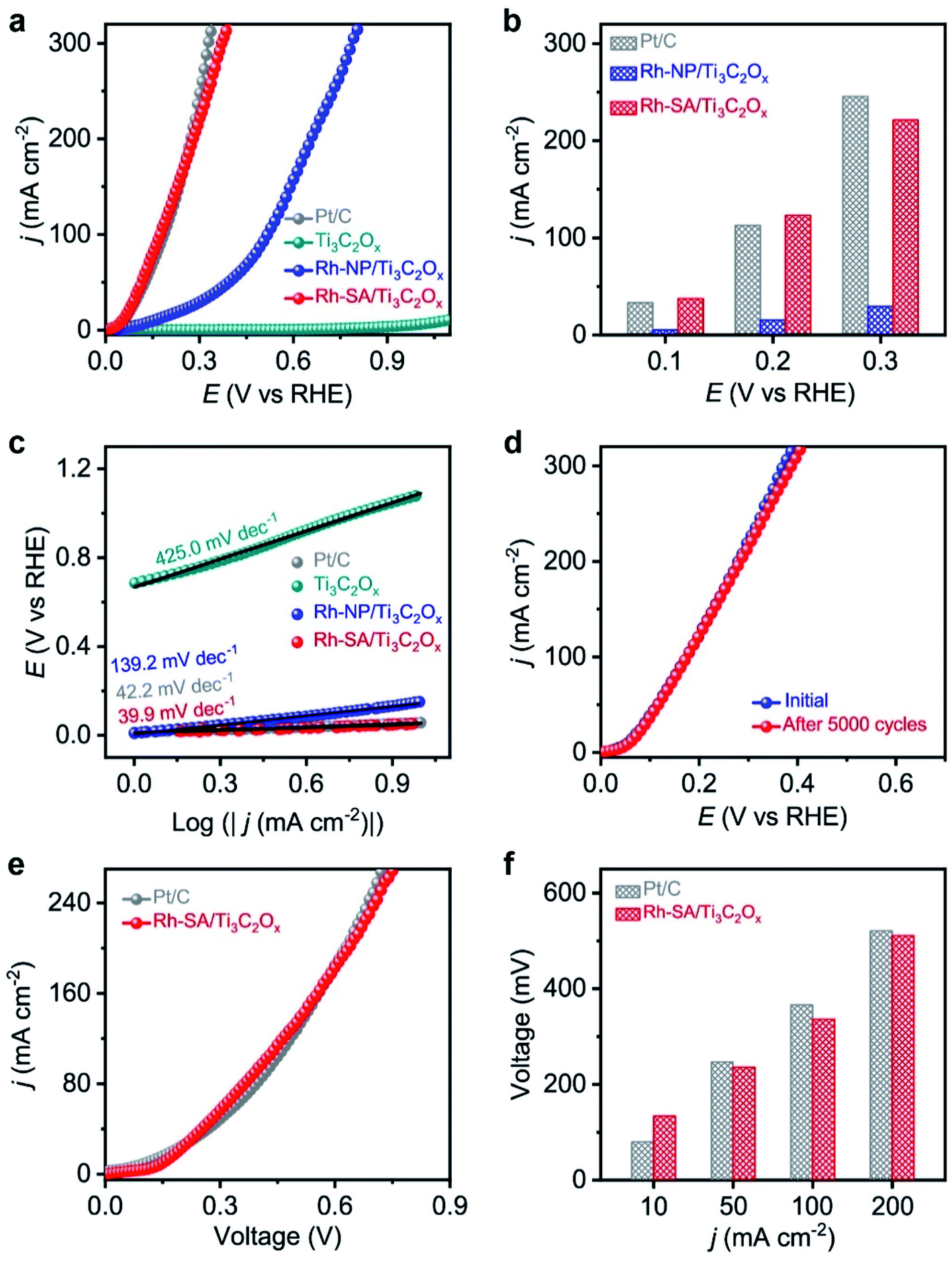 | ||
| Fig. 4 HzOR and OHzS electrochemical performances of the as-prepared catalysts measured under alkaline conditions: (a) the HzOR polarization curves of the Ti3C2Ox, Rh-NP/Ti3C2Ox, Rh-SA/Ti3C2Ox, and commercial Pt/C catalysts measured in 1.0 M KOH + 0.1 M N2H4 solution at a scan rate of 10 mV s−1; (b) the current densities at various potentials; (c) the corresponding Tafel plots; (d) HzOR polarization curves of Rh-SA/Ti3C2Ox initially and after 5000 cycles; (e) OHzS polarization curves in 1.0 M KOH + 0.1 M N2H4 solution using Rh-SA/Ti3C2Ox and commercial Pt/C as both the anode and cathode; (f) the voltages required to reach different current densities for OHzS. | ||
Specifically, Rh-SA/Ti3C2Ox achieves large anodic current densities of 37.5, 123.1, and 221.4 mA cm−2 at working potentials of 0.1, 0.2, and 0.3 V vs. RHE (Fig. 4b), respectively, which are far superior to those of Rh-NP/Ti3C2Ox and very close to those of commercial Pt/C. Also, Rh-SA/Ti3C2Ox outperforms most of the previously reported HzOR electrocatalysts (Table S6†). The corresponding Tafel plots (Fig. 4c) indicate that the Tafel slope of Rh-SA/Ti3C2Ox is only 39.9 mV dec−1, which is much lower than those of Ti3C2Ox (425.0 mV dec−1) and Rh-NP/Ti3C2Ox (139.3 mV dec−1) and even surpasses that of commercial Pt/C (42.2 mV dec−1), suggesting that it exhibits the most favorable catalytic kinetics towards the HzOR. As one of the critical factors for practical applications, the durability of Rh-SA/Ti3C2Ox was then evaluated by carrying out successive CV tests. As shown in Fig. 4d, the HzOR activity of the Rh-SA/Ti3C2Ox catalyst was well retained, showing negligible decay after 5000 potential cycles, demonstrating its excellent stability. In addition, a control experiment was performed (Fig. S14†), confirming that the Rh-SA/Ti3C2Ox catalyst cannot catalyze the direct decomposition of hydrazine in alkaline solution.56–58
Encouraged by the high activities and stabilities of the Rh-SA/Ti3C2Ox nanosheets towards the HER and HzOR, we further investigated their application as an OHzS electrocatalyst, used bifunctionally as an cathode and anode in a two-electrode electrolyzer. Fig. 4e shows the LSV curves of the OHzS of the Rh-SA/Ti3C2Ox and commercial Pt/C, in which enhanced energy efficiency can be seen using hydrazine oxidation to assist H2 production.59–61 Specifically, potentials of only 134, 236, 336, and 511 mV were required in this OHzS system to reach current densities of 10, 50, 100, and 200 mA cm−2 V (Fig. 4f), respectively, which are much closer to the values of Pt/C (80, 247, 366, and 521 mV).
Evaluation of Zn–H2 battery performance
Considering the highly efficient HER catalytic activity of the Rh-SA/Ti3C2Ox catalyst, a Zn–H2 battery hydrogen production system was constructed. As illustrated in Fig. 5a, this system was assembled using carbon paper supported Rh-SA/Ti3C2Ox as the cathode, Zn plate as the anode, and 2.0 M H2SO4 and 4.0 M NaOH as the catholyte and anolyte, respectively. A bipolar membrane (BPM) was used as a separator for preventing bulk neutralization of the acidic catholyte and alkaline anolyte. For comparison, the commercial 20 wt% Pt/C catalyst was also measured under the same conditions. As expected, Rh-SA/Ti3C2Ox provides a stable open-circuit voltage (OCV) of 1.26 V for the sole hydrogen production system, which is higher than that of Pt/C (1.21 V) and close to that of the theoretical value (1.32 V, the calculation details of which can be found in the ESI† file). The discharge polarization curves and the corresponding power density curves are depicted in Fig. 5c. As shown, the Rh-SA/Ti3C2Ox catalyst delivers a higher peak power density of 110.8 mW cm−2 at 175 mA cm−2, much better than that of Pt/C of 95.1 mW cm−2 at 156.5 mA cm−2. Moreover, the specific capacity over Rh-SA/Ti3C2Ox reaches 802.4 mA h gZn−1 at a current density of 10 mA cm−2 on the basis of consumed Zn mass (Fig. 5d), corresponding to an energy density of 985.2 W h kgZn−1 (close to the theoretical value of 1082.4 W h kgZn−1, see the calculation details in the ESI† file), which surpasses those of Pt/C (786.6 mA h gZn−1; 952.8 W h kgZn−1).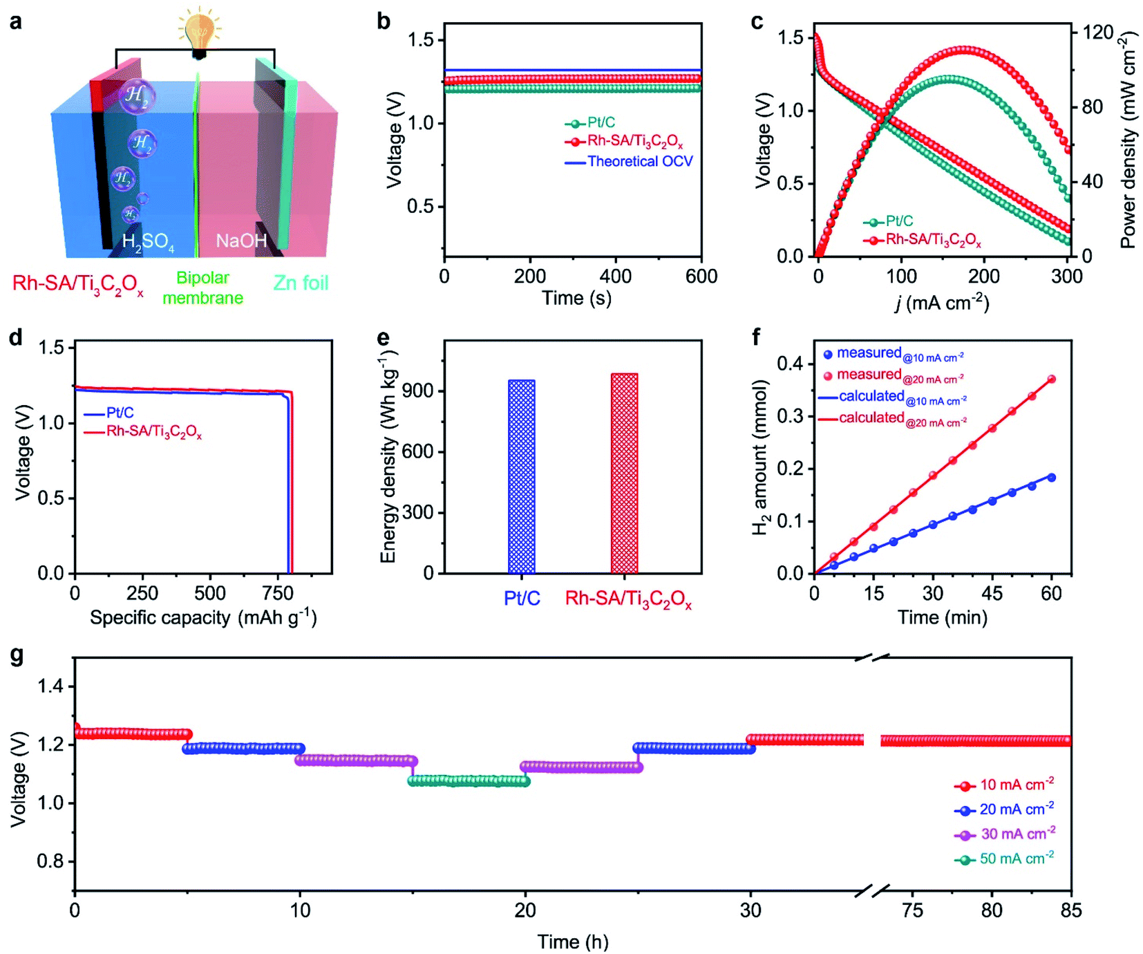 | ||
| Fig. 5 Zn–H2 battery hydrogen production system: (a) schematic illustration of the Rh-SA/Ti3C2Ox-based Zn–H2 battery hydrogen production system; (b) the open-circuit voltage curves; (c) polarization curves and the corresponding power densities; (d) the plots of voltage versus specific capacity at a scan rate of 10 mA cm−2, where the specific capacity was normalized to the mass of consumed Zn; (e) plots of energy densities; (f) the amount of generated H2 as a function of the reaction time at current densities of 10 and 20 mA cm−2, respectively; (g) discharge curves of the hydrogen production system based on Rh-SA/Ti3C2Ox with current densities from 10 to 50 mA cm−2 and the long-term stability tests at current densities of 10 mA cm−2 over 55 h. | ||
To testify the hydrogen-production efficiency of this system, the volumes of hydrogen produced upon the discharge process were recorded via the drainage gas collection method (Fig. S15†).62,63 The measured hydrogen yield fitted well to those of the theoretical calculations, thus the Faradaic efficiency (FE) was measured to be closed to 100% for H2 generation (Fig. 5f). Fig. 5g shows the high stability of the Rh-SA/Ti3C2Ox for around 5 h at various discharge current densities from 10 to 50 mA cm−2. In particular, the voltage shows almost no decay after the long-term stability tests at a current density of 10 mA cm−2 over 55 h, indicating its robust long-term discharging capability.
Evaluation of the self-driven dual hydrogen production system performance
Based on the successful assembly of the Zn–H2 battery and the excellent bifunctional catalytic activity of Rh-SA/Ti3C2Ox discussed above, a self-driven dual hydrogen production system was constructed. As illustrated in Fig. 6a, the self-driven dual hydrogen production system consists of the integration of a Zn–H2 battery using an Rh-SA/Ti3C2Ox cathode and Zn plate as the anode to drive the OHzS for H2 production (Fig. S16†). In this system, H2 is generated simultaneously via two pathways: the cathode of the Zn–H2 unit and the cathode of the OHzS. As shown in Fig. 6b, the total amount of hydrogen produced was collected. Based on the linear relationship between the H2 yield and the elapsed time, the H2 production rate was calculated as 45.77 mmol h−1, which outperforms the reported values of self-driven H2 production systems (Table S7†), demonstrating the exciting potential of this system for highly efficient H2 production. As shown in Fig. 6c, the voltage–time curve exhibits that this system can stably output a voltage of 0.75 V when the circuit is closed, as well as an open-circuit voltage of 1.27 V when the device is in an open circuit. Impressively, stable output voltage can be supplied over 58 h without obvious decay, demonstrating the robust durability and practical operability of the Rh-SA/Ti3C2Ox catalyst in this self-driven dual hydrogen production system.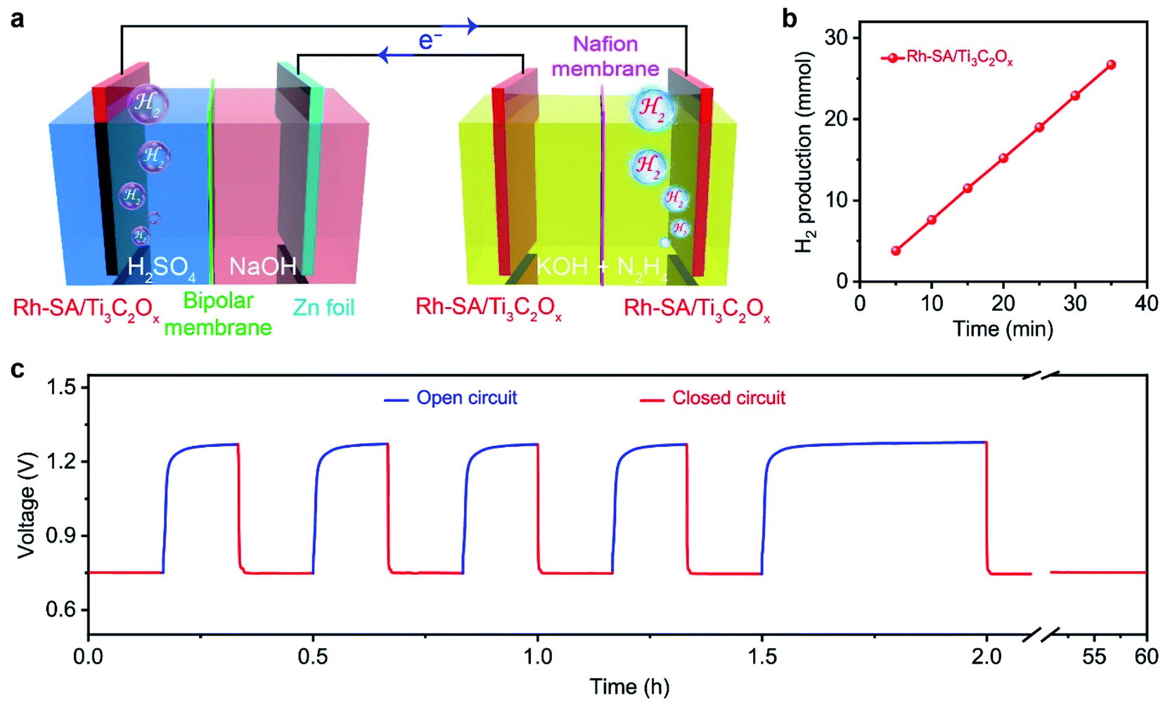 | ||
| Fig. 6 Self-driven dual hydrogen production system: (a) schematic illustration of the dual hydrogen production system self-driven by the Rh-SA/Ti3C2Ox catalyst; (b) the total amount of generated H2 as a function of the reaction time for this self-driven dual hydrogen production system; (c) the long-time voltage curve of the system at closed/open circuit. | ||
Computational studies
The high efficiency of the self-driven dual hydrogen production system originates from the good electrochemical performances of the Rh-SA/Ti3C2Ox catalyst in catalyzing the HER and HzOR. To shed light on and reveal the possible origin of the excellent catalytic activity of the Rh-SA/Ti3C2Ox catalyst, density functional theory (DFT) calculations were carried out for both the HER and HzOR. Firstly, the Gibbs free-energy (ΔG*H) of the adsorbed hydrogen atom is widely used to assess the HER catalytic activity of a catalyst, which has been advocated as a useful descriptor in the selection of good HER electrocatalysts, and when ΔG*H is close to 0 eV, the HER performance of the catalyst is good.64–67As illustrated in Fig. 7a, there are three different sites (1: O site; 2: Rh site; 3: Rh–O site) on the surface of the Rh-SA/Ti3C2Ox catalyst, which was selected as the active site for adsorbing H atom, as well as on Pt (111) and Rh (111) surface for comparison. As shown in Fig. 7b, the ΔG*H for a H atom adsorbed on Rh-SA/Ti3C2Ox is nearly 0 eV. Specifically, the optimal ΔG*H at the Rh–O site over the Rh-SA/Ti3C2Ox is −0.051 eV, while those at the Rh and O sites are −0.372 and 0.268 eV, respectively. Moreover, the atomic H adsorbed at the Rh–O site on the Rh-SA/Ti3C2Ox catalyst exhibits better ΔG*H than that adsorbed on the Pt (111) (−0.090 eV) and Rh (111) (−0.111 eV) surface, thus confirming that the atomically-dispersed Rh has enhanced HER catalytic activity; which is in accordance with the electrochemical experiments.
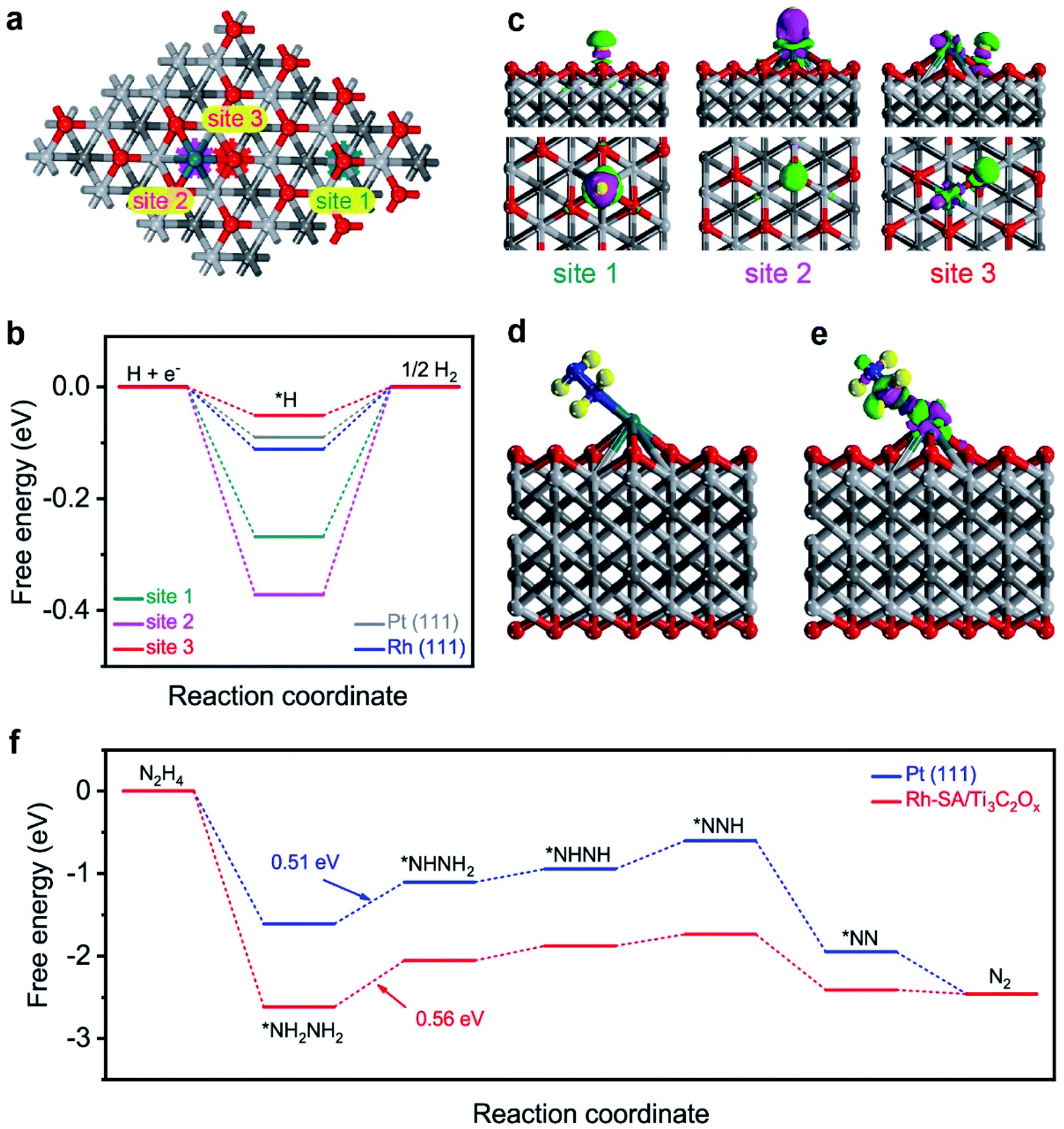 | ||
| Fig. 7 First-principles calculations of the HER and HzOR: (a) the three different sites over the Rh-SA/Ti3C2Ox catalyst surface: 1, O, 2, Rh, and 3 Rh–O sites; (b) free-energy profiles of the HER on the different sites over the Rh-SA/Ti3C2Ox, Pt(111), and Rh(111) surfaces; (c) side- and top-view of the three-dimensional charge density difference of the H-adsorbed configuration on the different sites over the Rh-SA/Ti3C2Ox catalyst surface, where the pink and green regions represent charge depletion and accumulation in the space, respectively; (d) optimized atomic structure model and (e) the charge density difference of the N2H4-adsorbed configuration on the Rh-SA/Ti3C2Ox catalyst; (f) free-energy profiles of the HzOR on the Rh-SA/Ti3C2Ox and Pt(111) surfaces. | ||
Furthermore, the electron density difference of the different sites of the adsorbed hydrogen atoms was calculated to investigate their electronic structure. As displayed in the charge difference diagram in Fig. 7c, a local charge redistribution induced by an atomically-dispersed Rh atom can be observed. It is thought that the electrons are enriched for the Rh–O site due to the electron transfer from Rh to the adjacent O atoms, and that more apparent charge transfer occurs between the H atom and the Rh–O site than that which occurs on the Rh and O sites. The delocalized electron distribution on H atom activation imposes a positive effect on the HER. This result is consistent with the free-energy profile shown in Fig. 7b.
Besides this, the theoretical deciphering of the HzOR process was also conducted. We first optimized the atomic structure for the Rh site over the Rh-SA/Ti3C2Ox adsorbed N2H4 molecule (Fig. 7d), and the calculation of its charge density difference was performed. As displayed in Fig. 7e, the electrons from the Rh atom were transferred to the adsorbed N2H4 and the charge redistribution was dominantly restricted around the Rh atom, proving the strong adsorption of N2H4 on Rh-SA/Ti3C2Ox. This electron localization behavior upon doping contributes towards the enhanced catalytic activity of Rh-SA/Ti3C2Ox.60,68 Furthermore, DFT calculations of the free energy of N2H4 adsorption (ΔG*N2H4) and each dehydrogenation step from adsorbed *NH2NH2 to N2 on the Rh site of the Rh-SA/Ti3C2Ox and Pt (111) surfaces were conducted. As indicated, the Rh-SA/Ti3C2Ox exhibits a more negative ΔG*N2H4 value of −2.62 eV compared to that of Pt (111) (−1.61 eV), suggesting more favorable N2H4 adsorption, which is undoubtedly important for the further catalytic oxidation process. More importantly, based on the free-energy change profiles of each elementary step (Fig. 7f), it can be concluded that the dehydrogenation of *NH2NH2 to *NHNH2 is the potential-determining step (PDS) for Rh-SA/Ti3C2Ox and Pt (111) towards the HzOR, and the PDS value of Rh-SA/Ti3C2Ox (0.56 eV) is very close to that of Pt (111) (0.51 eV). These results demonstrate that the introduction of single Rh atoms largely optimizes the electronic structure of Ti3C2Ox, thus facilitating the thermodynamic behavior of Rh-SA/Ti3C2Ox for both hydrogen adsorption in the HER and dehydrogenation process in the HzOR.
Conclusion
In summary, we have demonstrated that an integrated electrode composed of highly-dispersed single Rh atoms supported on an oxygen-functionalized Ti3C2Ox MXene (Rh-SA/Ti3C2Ox) catalyst exhibits benchmark electrocatalytic activities toward both the pH-universal HER and HzOR. Specifically, Rh-SA/Ti3C2Ox only requires low overpotentials of 23 mV (0.1 M H2SO4), 85 mV (1 M PBS), and 29 mV (0.1 M KOH) for the HER to afford a current density of −10 mA cm−2, which are comparable to those of Pt/C. Also, it offers a current density of 37.5 mA cm−2 at a working potential of 0.1 V vs. RHE for the alkaline HzOR. Furthermore, when the Rh-SA/Ti3C2Ox catalyst is applied as the cathode in an asymmetric alkali–acid Zn–H2 battery, an FE of nearly 100% for H2 generation can be achieved. More importantly, a proof-of-concept self-driven dual hydrogen production system was constructed via the combined utilization of a Zn–H2 battery to drive the OHzS for H2 production. Notably, an ultra-high H2 generation rate of 45.77 mmol h−1 can be reached in such a designed system. DFT calculations indicate that the atomically-dispersed single Rh atoms significantly decrease the free energy changes of not only the H adsorption but also the dehydrogenation of adsorbed NHNH2 on the Rh-SA/Ti3C2Ox, making the HER and HzOR pathways on the designed catalyst energetically-favorable processes.Author contributions
X. Y. P. designed the electrocatalysts and performed the electrochemical experiments, to which Y. Q. contributed. X. Y. P. and Y. Y. M. co-analyzed the electrochemical data. X. Y. P. performed the first-principles calculations and analyzed the results. X. X. K. and J. L. carried out the electron microscopy characterization and analysis, to which J. Q. S. and S. S. Z. contributed. X. J. L., X. Z. W., and J. L. co-proposed the electrocatalytic mechanism. X. J. L., X. Z. W., and J. L. co-supervised the project. All the authors contributed to the overall scientific interpretation and edited the manuscript.Conflicts of interest
There are no conflicts to declare.Acknowledgements
This work was financially supported by the National Natural Science Foundation of China (22075211, 21601136, 51971157, 12074017 and 51621003), the Tianjin Science Fund for Distinguished Young Scholars (19JCJQJC61800), the Beijing Municipal High-Level Innovative Team Building Program (IDHT20190503), the Guangdong Province Higher Vocational Colleges & Schools Pearl River Scholar Funded Scheme (2016), the Guangdong Third Generation Semiconductor Engineering Technology Development Center (2020GCZX007), and the Science and Technology Development Fund of Tianjin Education Commission for Higher Education (2018KJ126). The authors are also thankful for the facility support at the BL14W1 beamline of the Shanghai Synchrotron Radiation Facility (SSRF, China) and thank the Beijing Super Cloud Computing Center for providing the computational resources and materials studio.References
- X. Zou and Y. Zhang, Chem. Soc. Rev., 2015, 44, 5148–5180 RSC.
- X. Wu, S. Zhou, Z. Wang, J. Liu, W. Pei, P. Yang, J. Zhao and J. Qiu, Adv. Energy Mater., 2019, 9, 1901333 CrossRef.
- M. D. Symes and L. Cronin, Nat. Chem., 2013, 5, 403–409 CrossRef CAS PubMed.
- M. S. Dresselhaus and I. L. Thomas, Nature, 2001, 414, 332–337 CrossRef CAS PubMed.
- Z. W. Seh, J. Kibsgaard, C. F. Dickens, I. Chorkendorff, J. K. Norskov and T. F. Jaramillo, Science, 2017, 355, eaad4998 CrossRef PubMed.
- D. Kong, J. J. Cha, H. Wang, H. R. Lee and Y. Cui, Energy Environ. Sci., 2013, 6, 3553–10295 RSC.
- J. Zhang and L. Dai, Angew. Chem., Int. Ed., 2016, 55, 13296–13298 CrossRef CAS PubMed.
- X. He, Y. Zi, H. Guo, H. Zheng, Y. Xi, C. Wu, J. Wang, W. Zhang, C. Lu and Z. L. Wang, Natl. Sci. Rev., 2021, 8, nwaa204 CrossRef.
- J. Zhang and L. Dai, Angew. Chem., Int. Ed., 2016, 55, 13296–13300 CrossRef CAS.
- X. He, Y. Zi, H. Guo, H. Zheng, Y. Xi, C. Wu, J. Wang, W. Zhang, C. Lu and Z. L. Wang, Adv. Funct. Mater., 2017, 27, 1604378 CrossRef.
- X. Liu, J. He, S. Zhao, Y. Liu, Z. Zhao, J. Luo, G. Hu, X. Sun and Y. Ding, Nat. Commun., 2018, 9, 4365 CrossRef.
- Z. Lu, M. Sun, T. Xu, Y. Li, W. Xu, Z. Chang, Y. Ding, X. Sun and L. Jiang, Adv. Mater., 2015, 27, 2361 CrossRef CAS.
- G. Feng, Y. Kuang, P. Li, N. Han, M. Sun, G. Zhang and X. Sun, Adv. Sci., 2017, 4, 1600179 CrossRef PubMed.
- Y. Gu, A. Wu, Y. Jiao, H. Zheng, X. Wang, Y. Xie, L. Wang, C. Tian and H. Fu, Angew. Chem., Int. Ed., 2021, 60, 6673–6681 CrossRef CAS PubMed.
- Y. Liu, X. Li, Q. Zhang, W. Li, Y. Xie, H. Liu, L. Shang, Z. Liu, Z. Chen, L. Gu, Z. Tang, T. Zhang and S. Lu, Angew. Chem., Int. Ed., 2020, 59, 1718–1726 CrossRef CAS.
- X. F. Lu, L. Yu and X. W. D. Lou, Sci. Adv., 2019, 5, eaav6009 CrossRef CAS PubMed.
- J. Zhang, Y. Huang, X. Lu, J. Yang and Y. Tong, ACS Sustainable Chem. Eng., 2021, 9, 8306–8314 CrossRef CAS.
- X. Lu, K.-h. Ye, S. Zhang, J. Zhang, J. Yang, Y. Huang and H. Ji, Chem. Eng. J., 2022, 428, 131027 CrossRef CAS.
- P. B. Selvadurai A, T. Xiong, P. Huang, Q. Tan, Y. Huang, H. Yang and M. S. Balogun, J. Mater. Chem. A, 2021, 9, 16906–16916 RSC.
- F. Yang, T. Xiong, P. Huang, S. Zhou, Q. Tan, H. Yang, Y. Huang and M. S. Balogun, Chem. Eng. J., 2021, 423, 130279 CrossRef CAS.
- L.-S. Wu, X.-P. Wen, H. Wen, H.-B. Dai and P. Wang, J. Power Sources, 2019, 412, 71–77 CrossRef CAS.
- J. Y. Zhang, H. Wang, Y. Tian, Y. Yan, Q. Xue, T. He, H. Liu, C. Wang, Y. Chen and B. Y. Xia, Angew. Chem., Int. Ed., 2018, 57, 7649–7653 CrossRef CAS.
- Y. Meng, X. Zou, X. Huang, A. Goswami, Z. Liu and T. Asefa, Adv. Mater., 2014, 26, 6510–6516 CrossRef CAS PubMed.
- C. Tang, R. Zhang, W. Lu, Z. Wang, D. Liu, S. Hao, G. Du, A. M. Asiri and X. Sun, Angew. Chem., Int. Ed., 2017, 56, 842–846 CrossRef CAS PubMed.
- X. Meng, C. Ma, L. Jiang, R. Si, X. Meng, Y. Tu, L. Yu, X. Bao and D. Deng, Angew. Chem., Int. Ed., 2020, 59, 10502–10507 CrossRef CAS PubMed.
- Y. F. Cheng, S. K. Lu, F. Liao, L. B. Liu, Y. Q. Li and M. W. Shao, Adv. Funct. Mater., 2017, 27, 1700359 CrossRef.
- C. Zhang, H. Liu, Y. Liu, X. Liu, Y. Mi, R. Guo, J. Sun, H. Bao, J. He, Y. Qiu, J. Ren, X. Yang, J. Luo and G. Hu, Small Methods, 2020, 4, 2000208 CrossRef CAS.
- M. Ghidiu, M. R. Lukatskaya, M. Q. Zhao, Y. Gogotsi and M. W. Barsoum, Nature, 2014, 516, 78–81 CrossRef CAS PubMed.
- A. Lipatov, M. Alhabeb, M. R. Lukatskaya, A. Boson, Y. Gogotsi and A. Sinitskii, Adv. Electron. Mater., 2016, 2, 1600255 CrossRef.
- D. Zhao, R. Zhao, S. Dong, X. Miao, Z. Zhang, C. Wang and L. Yin, Energy Environ. Sci., 2019, 12, 2422–2432 RSC.
- J. Li, X. Yuan, C. Lin, Y. Yang, L. Xu, X. Du, J. Xie, J. Lin and J. Sun, Adv. Energy Mater., 2017, 7, 1602725 CrossRef.
- J. Tang, T. S. Mathis, N. Kurra, A. Sarycheva, X. Xiao, M. N. Hedhili, Q. Jiang, H. N. Alshareef, B. Xu, F. Pan and Y. Gogotsi, Angew. Chem., Int. Ed., 2019, 58, 17849–17855 CrossRef CAS PubMed.
- V. Ramalingam, P. Varadhan, H. C. Fu, H. Kim, D. Zhang, S. Chen, L. Song, D. Ma, Y. Wang, H. N. Alshareef and J. H. He, Adv. Mater., 2019, 31, 1903841 CrossRef CAS PubMed.
- J. Zhang, N. Kong, S. Uzun, A. Levitt, S. Seyedin, P. A. Lynch, S. Qin, M. Han, W. Yang, J. Liu, X. Wang, Y. Gogotsi and J. M. Razal, Adv. Mater., 2020, 32, 2001093 CrossRef CAS PubMed.
- N. Sun, Q. Zhu, B. Anasori, P. Zhang, H. Liu, Y. Gogotsi and B. Xu, Adv. Funct. Mater., 2019, 29, 1906282 CrossRef CAS.
- H. Bao, Y. Qiu, X. Peng, J.-a. Wang, Y. Mi, S. Zhao, X. Liu, Y. Liu, R. Cao, L. Zhuo, J. Ren, J. Sun, J. Luo and X. Sun, Nat. Commun., 2021, 12, 238 CrossRef CAS.
- L. Han, S. Song, M. Liu, S. Yao, Z. Liang, H. Cheng, Z. Ren, W. Liu, R. Lin, G. Qi, X. Liu, Q. Wu, J. Luo and H. L. Xin, J. Am. Chem. Soc., 2020, 142, 12563–12567 CrossRef CAS PubMed.
- J. Zhang, T. Wang, P. Liu, Z. Liao, S. Liu, X. Zhuang, M. Chen, E. Zschech and X. Feng, Nat. Commun., 2017, 8, 15437 CrossRef CAS.
- G. Q. Zhao, K. Rui, S. X. Dou and W. Sun, Adv. Funct. Mater., 2018, 28, 1803291 CrossRef.
- J. Zhu, L. Hu, P. Zhao, L. Y. S. Lee and K.-Y. Wong, Chem. Rev., 2019, 120, 851–918 CrossRef PubMed.
- Y. Shi and B. Zhang, Chem. Soc. Rev., 2016, 45, 1529–1541 RSC.
- R. Subbaraman, D. Tripkovic, D. Strmcnik, K. C. Chang, M. Uchimura, A. P. Paulikas, V. Stamenkovic and N. M. Markovic, Science, 2011, 334, 1256–1260 CrossRef CAS.
- L. Huo, B. Liu, Z. Gao and J. Zhang, J. Mater. Chem. A, 2017, 5, 18494–18501 RSC.
- C. Lv, Z. Huang, Q. Yang and C. Zhang, Energy Technol., 2018, 6, 1707–1714 CrossRef CAS.
- X. Geng, W. Sun, W. Wu, B. Chen, A. Al-Hilo, M. Benamara, H. Zhu, F. Watanabe, J. Cui and T. P. Chen, Nat. Commun., 2016, 7, 10672 CrossRef CAS.
- X. F. Lu, L. Yu, J. Zhang and X. W. Lou, Adv. Mater., 2019, 31, 1900699 CrossRef.
- M. Q. Wang, C. Ye, H. Liu, M. Xu and S. J. Bao, Angew. Chem., Int. Ed., 2018, 57, 1963–1967 CrossRef CAS.
- D. Voiry, M. Chhowalla, Y. Gogotsi, N. A. Kotov, Y. Li, R. M. Penner, R. E. Schaak and P. S. Weiss, ACS Nano, 2018, 12, 9635–9638 CrossRef CAS.
- J. Kibsgaard and T. F. Jaramillo, Angew. Chem., Int. Ed., 2014, 53, 14433–14437 CrossRef CAS.
- R. Zhang, X. Wang, S. Yu, T. Wen, X. Zhu, F. Yang, X. Sun, X. Wang and W. Hu, Adv. Mater., 2017, 29, 1605502 CrossRef.
- J. Yang, B. Chen, X. Liu, W. Liu, Z. Li, J. Dong, W. Chen, W. Yan, T. Yao, X. Duan, Y. Wu and Y. Li, Angew. Chem., Int. Ed., 2018, 57, 9495–9500 CrossRef CAS.
- H. Sun, C. Tian, G. Fan, J. Qi, Z. Liu, Z. Yan, F. Cheng, J. Chen, C. P. Li and M. Du, Adv. Funct. Mater., 2020, 30, 1910596 CrossRef CAS.
- D. Merki, H. Vrubel, L. Rovelli, S. Fierro and X. Hu, Chem. Sci., 2012, 3, 2515–2525 RSC.
- C. C. McCrory, S. Jung, I. M. Ferrer, S. M. Chatman, J. C. Peters and T. F. Jaramillo, J. Am. Chem. Soc., 2015, 137, 4347–4357 CrossRef CAS.
- J. X. Feng, J. Q. Wu, Y. X. Tong and G. R. Li, J. Am. Chem. Soc., 2018, 140, 610–617 CrossRef CAS PubMed.
- H. L. Wang, J. M. Yan, Z. L. Wang, S. I. O and Q. Jiang, J. Mater. Chem. A, 2013, 1, 14957–14962 RSC.
- S. K. Singh and Q. Xu, Catal. Sci. Technol., 2013, 3, 1889–1900 RSC.
- H. L. Wang, J. M. Yan, S. J. Li, X. W. Zhang and Q. Jiang, J. Mater. Chem. A, 2015, 3, 121–124 RSC.
- Y. Li, J. Zhang, Y. Liu, Q. Qian, Z. Li, Y. Zhu and G. Zhang, Sci. Adv., 2020, 6, eabb4197 CrossRef CAS.
- Y. Liu, J. Zhang, Y. Li, Q. Qian, Z. Li, Y. Zhu and G. Zhang, Nat. Commun., 2020, 11, 1853 CrossRef CAS PubMed.
- Z. Wang, L. Xu, F. Huang, L. Qu, J. Li, K. A. Owusu, Z. Liu, Z. Lin, B. Xiang, X. Liu, K. Zhao, X. Liao, W. Yang, Y. B. Cheng and L. Mai, Adv. Energy Mater., 2019, 9, 1900390 CrossRef.
- X. Peng, S. Zhao, Y. Mi, L. Han, X. Liu, D. Qi, J. Sun, Y. Liu, H. Bao, L. Zhuo, H. L. Xin, J. Luo and X. Sun, Small, 2020, 16, 2002888 CrossRef CAS.
- G. F. Chen, T. Y. Ma, Z. Q. Liu, N. Li, Y.-Z. Su, K. Davey and S. Z. Qiao, Adv. Funct. Mater., 2016, 26, 3314–3323 CrossRef CAS.
- J. K. Nørskov, T. Bligaard, A. Logadottir, J. R. Kitchin, J. G. Chen, S. Pandelov and U. Stimming, J. Electrochem. Soc., 2005, 152, J23–J26 CrossRef.
- J. Greeley, T. F. Jaramillo, J. Bonde, I. B. Chorkendorff and J. K. Norskov, Nat. Mater., 2006, 5, 909–913 CrossRef CAS.
- M. Mavrikakis, Nat. Mater., 2006, 5, 847–848 CrossRef CAS.
- Y. Liu, Q. Feng, W. Liu, Q. Li, Y. Wang, B. Liu, L. Zheng, W. Wang, L. Huang, L. Chen, X. Xiong and Y. Lei, Nano Energy, 2021, 81, 105641 CrossRef CAS.
- Q. Qian, J. Zhang, J. Li, Y. Li, X. Jin, Y. Zhu, Y. Liu, Z. Li, A. El-Harairy, C. Xiao, G. Zhang and Y. Xie, Angew. Chem., Int. Ed., 2020, 60, 5984–5993 CrossRef.
Footnote |
| † Electronic supplementary information (ESI) available. See DOI: 10.1039/d1ta07375c |
| This journal is © The Royal Society of Chemistry 2022 |