
 Open Access Article
 This Open Access Article is licensed under a Creative Commons Attribution-Non Commercial 3.0 Unported Licence
Phase formation and performance of solid state reactive sintered Ce0.8Gd0.2O2−δ–FeCo2O4 composites
Liudmila
Fischer
ab,
Kerstin
Neuhaus
c,
Christina
Schmidt
c,
Ke
Ran
 de,
Patrick
Behr
a,
Stefan
Baumann
*a,
Joachim
Mayer
de and
Wilhelm A.
Meulenberg
ab
de,
Patrick
Behr
a,
Stefan
Baumann
*a,
Joachim
Mayer
de and
Wilhelm A.
Meulenberg
ab
aForschungszentrum Jülich GmbH, Institute of Energy and Climate Research, IEK-1 Materials Synthesis and Processing (IEK-1), 52425 Jülich, Germany. E-mail: s.baumann@fz-juelich.de
bFaculty of Science and Technology, Inorganic Membranes, University of Twente, 7500 AE Enschede, The Netherlands
cForschungszentrum Jülich GmbH, Institute of Energy and Climate Research, IEK-12, Helmholtz-Institute Münster: Ionics in Energy Storage, Corrensstr. 46, 48149 Münster, Germany
dCentral Facility for Electron Microscopy GFE, RWTH Aachen University, 52074 Aachen, Germany
eErnst Ruska-Centre for Microscopy and Spectroscopy with Electrons ER-C, Forschungszentrum Jülich GmbH, 52425 Jülich, Germany
First published on 13th October 2021
Abstract
Reactive sintering of dual phase composites for use as oxygen transport membranes is a promising method enabling lower sintering temperatures as well as low-cost raw materials. Ce0.8Gd0.2O2−δ–FeCo2O4 composites with different nominal weight ratios from 60![[thin space (1/6-em)]](https://www.rsc.org/images/entities/char_2009.gif) :40 to 90:10 are processed by reactive sintering of commercial Ce0.8Gd0.2O2−δ, Fe2O3, and Co3O4 powders. The phases formed in situ during sintering are investigated qualitatively and quantitatively by means of XRD and Rietveld refinement as well as transmission electron microscopy. Besides gadolinia-doped ceria, two Fe/Co-spinel phases are in equilibrium in agreement with the phase diagram. Moreover, a donor-doped GdFeO3-based perovskite (Gd,Ce)(Fe,Co)O3 showing electronic conductivity is formed. Due to these intense phase reactions, the composition of each individual phase is assessed for all composites and their functional properties are discussed. The oxygen permeation performances of the composites are measured including their dependence on temperature and the potential limiting steps are discussed. The results reveal that the phase reactions support the formation of the desired mixed ionic electronic conductivity achieving percolation at low nominal spinel contents. The specific microstructure plays an extremely important role in the membrane performance and, thus, special attention should be paid to this in future research about dual phase membranes.
:40 to 90:10 are processed by reactive sintering of commercial Ce0.8Gd0.2O2−δ, Fe2O3, and Co3O4 powders. The phases formed in situ during sintering are investigated qualitatively and quantitatively by means of XRD and Rietveld refinement as well as transmission electron microscopy. Besides gadolinia-doped ceria, two Fe/Co-spinel phases are in equilibrium in agreement with the phase diagram. Moreover, a donor-doped GdFeO3-based perovskite (Gd,Ce)(Fe,Co)O3 showing electronic conductivity is formed. Due to these intense phase reactions, the composition of each individual phase is assessed for all composites and their functional properties are discussed. The oxygen permeation performances of the composites are measured including their dependence on temperature and the potential limiting steps are discussed. The results reveal that the phase reactions support the formation of the desired mixed ionic electronic conductivity achieving percolation at low nominal spinel contents. The specific microstructure plays an extremely important role in the membrane performance and, thus, special attention should be paid to this in future research about dual phase membranes.
Introduction
The development of ceramic dual-phase materials for Oxygen Transport Membranes (OTMs) has attracted much attention in the scientific world. These mixed ionic-electronic conductors (MIECs) are operated at elevated temperatures, i.e. 700–900 °C, and have the potential for improving the performance and reducing the cost of several industrial gas separation processes due to high energy efficiency.1,2 If the membrane separates two gas phases with different oxygen partial pressures pO2, oxygen molecules will be reduced to oxygen ions at the surface of the high pO2-side taking up in sum four electrons. The ions diffuse through the membrane to the low pO2-side where they recombine to form oxygen molecules releasing the electrons again. These electrons transfer back to the high pO2-side simultaneously due to the MIEC character of the membrane material.3 However, classical single phase MIEC materials, mainly perovskites, suffer from stability issues under operating conditions. Therefore, composite membranes, a combination of both ion and electron conducting ceramic phases, have attracted major interest in recent years.4–8 Such composites provide the major advantage that two inherently stable materials can be selected provided that their properties such as conductivities, thermal expansion behaviour, and inertness match well. The phase mixture in the composite has to provide separate but continuous pathways for both oxygen ions and electrons and, thus, a percolation of the phases is required. The number of excellent oxygen ion conductors is limited mainly to doped zirconia or ceria, whereby Gd-doped ceria (CGO) shows the highest ionic conductivity in particular at lower temperatures.9 In contrast, there is a lot of choice of ceramic electronic conductors, which typically crystallize in perovskite or spinel structure both consisting of transition metal elements typically providing electron hole conductivity via small polaron hopping.10–15Normally, phases are selected that do not react with each other during sintering and operation in order to maintain these conductive pathways. Recent studies, however, revealed that CGO mixed with Fe/Co-spinel (Fe3−xCoxO4) forms an additional orthorhombic perovskite phase during sintering, which even improved the overall performance.16–18 It turned out that the perovskite phase is GdFeO3-based with Ce and Co on the A-site and B-site, respectively. The Ce4+ substituting Gd3+ acts as a donor and, thus, electronic conductivity is introduced.19–22
This orthorhombic perovskite phase is quite stable and forms distinct grains rather than being a grain boundary phase as speculated in the literature.10 Obviously, the perovskite phase does not have significant negative effects on the ion- or electron-conducting pathways, i.e. ambipolar conductivity. Obviously, this unintended formation of the perovskite phase is not undesired and in contrast might even have positive effects. Lin et al.17 hypothesized an increase in ionic conductivity of the ceria phase due to the extraction of Gd, which otherwise would be segregated at the ceria–ceria grain boundaries resulting in ion transport blocking space charge layers. The maximum performance was observed at a low nominal spinel concentration of 15 wt%,19 which is well below 30 vol% often referred to as the percolation threshold. However, percolation is affected by many factors24 in particular in real microstructures. Considering uncorrelated equal-sized spheres in the so-called “swiss-cheese” model the percolation limit is calculated to be 28.95 vol%.23 Therefore, 30 vol% appears to be a useful guideline although it does not represent a sharp limit. Certain percolating paths can occur well below that. Nevertheless, sufficient electronic conduction requires enough “strong” paths with certain conductivity. On the other hand, the perovskite formation takes place at the expense of the ceria volume fraction reducing oxygen ion conductance, which is considered rate limiting, and increasing the volume fraction of the electronic conducting phases compared to the nominal composition.
Therefore, in order to better understand the influence of the several phases formed during solid state reactive sintering, various nominal combinations of Ce0.8Gd0.2O2−δ (CGO) and FeCo2O4 (FCO) are investigated in this work. The resulting phase mixtures are analysed qualitatively and quantitatively based on X-ray diffraction and Rietveld refinement, respectively. Individual phase compositions are determined and their influence on the functional properties, i.e. conductivity and oxygen permeance, is discussed.
Experimental
Sample preparation
Ce0.8Gd0.2O2−δ (CGO), Fe2O3 and Co3O4 powders were used for the Solid-State Reactive Sintering (SSRS) process. Respective amounts of powders were weighed for nominal CGO-FeCo2O4 compositions with wt%-ratios of 60:40, 65:35, 70:30, 75:25, 80:20, 85:15 and 90:10. The powder mixtures were ball milled in ethanol for 48 h on a roller bench with 175 rpm. After drying in ambient air at 70° the powder mixtures were pressed with a uniaxial press in disc-shaped membranes with d = 20 mm. The discs were sintered with a heating rate of 5 K min−1 to 1200 °C and a dwell time of 5 hours. At sintering temperature the spinel partially reduces into a high temperature monoxide phase with rocksalt structure. Therefore, a slow rate of 0.5 K min−1 between 900 and 800 °C is implemented in the cooling cycle in order to ensure complete reoxidation of the high temperature Co/Fe-monoxide phase to the spinel phase stable at operating temperatures according to the Fe3−xCoxO4 phase diagram.16
The sintered discs were ground to approx. 1 mm thickness in 2 steps (by WS FLEX 18C) with SiC papers of P 800 and P 1200 grit, respectively. Subsequently, porous LSCF (La0.58Sr0.4Co0.2Fe0.8O3−δ) catalytic activation layers with a thickness of approx. 5 μm were applied via screen printing on both sides of the discs and calcined at 1100 °C for 5 hours.
Single-phase powders of spinel as well as the resulting perovskite, i.e. Gd0.85Ce0.15Fe0.75Co0.25O3, were synthesized by gelation and complexation of an aqueous solution of metal nitrates known as the Pechini-method.25
Characterization methods
| FCO [wt%] | Fluorite (CGO) Fm![[3 with combining macron]](https://www.rsc.org/images/entities/char_0033_0304.gif) m m |
Fe-rich spinel Fd3m | Co-rich spinel Fd3m | Perovskite (GCFCO) Pnma | ||||||
|---|---|---|---|---|---|---|---|---|---|---|
| F [wt%] | a = b = c [Å] | F [wt%] | a = b = c [Å] | F [wt%] | a = b = c [Å] | F [wt%] | Lattice parameter [Å] | |||
| a | b | c | ||||||||
| 10 | 82.1[3] | 5.4213[5] | 0 | — | 7.1[3] | 8.1309[2] | 10.7 [2] | 5.3370[3] | 5.6121[4] | 7.6467[8] |
| 15 | 73.5[3] | 5.4215[5] | 7.8[2] | 8.2483[8] | 5.1[2] | 8.1321[3] | 13.6[2] | 5.3376[4] | 5.6147[5] | 7.6492[8] |
| 20 | 69.4[3] | 5.4221[4] | 4.2[2] | 8.2426[9] | 14.5[2] | 8.1795[2] | 11.9[2] | 5.3421[4] | 5.6191[4] | 7.6583[7] |
| 25 | 62.5[3] | 5.4227[5] | 9.2[2] | 8.3032[8] | 13.3[2] | 8.1436[2] | 12.9[2] | 5.3404[3] | 5.6163[4] | 7.6549[7] |
| 30 | 61.3[3] | 5.4220[4] | 15.5[2] | 8.2994[8] | 11.8[2] | 8.1490[2] | 11.4[2] | 5.3399[3] | 5.6141[5] | 7.6576[8] |
| 35 | 56.3[3] | 5.4201[4] | 16.4[2] | 8.2967[8] | 17.0[2] | 8.1580[2] | 10.3[2] | 5.3409[3] | 5.6121[4] | 7.6368[8] |
| 40 | 51.7[3] | 5.4211[5] | 20.3[2] | 8.2966[9] | 18.2[2] | 8.1461[3] | 9.8[2] | 5.3395[3] | 5.6121[4] | 7.6410[8] |
TEM specimens were cut from the CGO-FCO pellets by focused ion beam (FIB) milling using an FEI Strata 400 system with a Ga ion beam. Further thinning and cleaning were performed with an Ar ion beam in a Fischione Nanomill 1040 at 900 eV and 500 eV beam energy respectively. TEM, energy-filtered TEM imaging and electron diffraction were performed using an FEI Tecnai F20 at 200 kV. High-resolution high-angle annular dark-field (HAADF) imaging was conducted with an FEI Titan G2 80-200 ChemiSTEM microscope equipped with an XFEG and a probe Cs corrector.26
In order to distinguish the oxygen partial pressure dependent electronic conductivity contribution from the total conductivity, Hebb–Wagner measurements27,28 were conducted. The Pt micro contact described above was additionally surrounded by a gas tight encapsulation (IP 041 glass paste by Heraeus GmbH), using the same measurement setup as for the standard DC measurements.
The experimental error of both methods is ±5%.
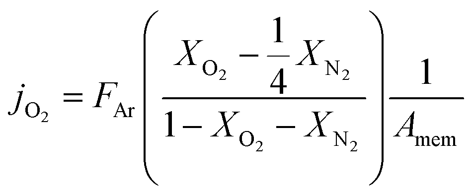 | (1) |
 reflects the O2/N2 ratio in the air feed assuming that the leak is not gas selective.
Since the oxygen partial pressure in the permeate gas is temperature dependent, the driving force of the permeation rate is not constant during the measurement. Moreover, the sample thickness after grinding has a deviation from the target, i.e. 1 mm, of ±8%. Therefore, the permeance, i.e. driving force normalized permeation rate, normalized to the reference thickness L0 = 1 mm is calculated assuming Wagner behaviour using
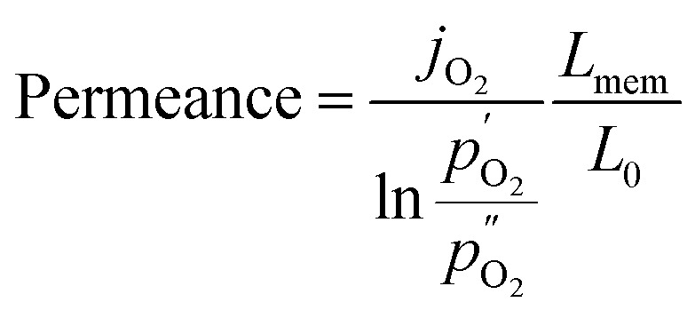 | (2) |
 and
and  being the oxygen partial pressures in the retentate and permeate gas, respectively, and Lmem the actual membrane thickness.
The overall experimental error cannot be calculated precisely. It is assumed to be ±10%, which is well accepted in the literature.
Results and discussion
Microstructure
The phase identification has been performed via XRD. All samples consist of ceria (Ce0.8Gd0.2O2−δ) and spinel-type (FeCo2O4) phases with the additional orthorhombic perovskite structure GdFeO3 as expected without the formation of any other phases, Fig. 1. The change in the spinel fraction in the composite is evident by the decrease of the intensities of the corresponding reflections in the XRD patterns in the region of 35 ≤ 2θ ≤ 38°. Moreover, reflection splitting is visible revealing two coexisting spinel phases in accordance with the phase diagram.16 The phases are homogeneously distributed as indicated in Fig. 2. The three crystallographic phases are confirmed as fluorite (Ce1−xGdxO2), spinel (Fe3−xCoxO4) and perovskite (GdFeO3) and exemplarily shown by the HAADF images in Fig. 3 for the 60:40 CGO-FCO composite. The weight fractions and lattice parameters of each phase were determined by Rietveld refinement as shown in Table 1. In agreement with the phase diagram of the FexCo3−xO4 system two types of spinel are present in the range of 0.65 ≤ Fe ≤ 1.07, i.e. Co-rich (normal spinel) and Fe-rich (inverse spinel). Indeed, both spinels are detected for all composites except 90:10 proportion, in which only of the Co-rich normal spinel is found. The resulting weight fraction of each phase is plotted versus the nominal spinel content in Fig. 4.
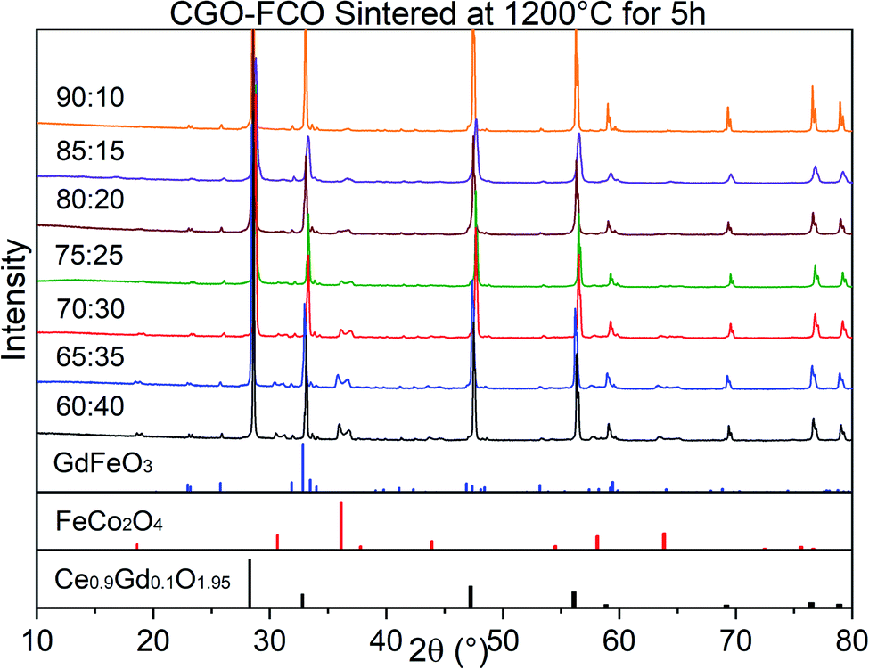 | ||
| Fig. 1 XRD patterns of the CGO-FCO composites in a row with various FCO contents sintered at 1200 °C for 5 h. At the bottom, reference reflections are shown for the perovskite (01-072-9909) in blue, spinel (01-074-3417) in red, and fluorite (01-075-0161) in black. ICCD numbers are given in brackets. | ||
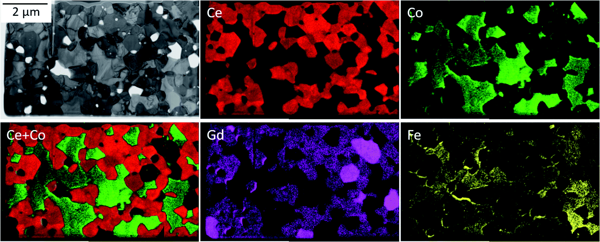 | ||
| Fig. 2 Energy-filtered TEM (EFTEM) analysis identifying three main phases: Gd-doped ceria (red), Fe/Co-oxide (green) and the GdFeO3-based perovskite (bright magenta). | ||
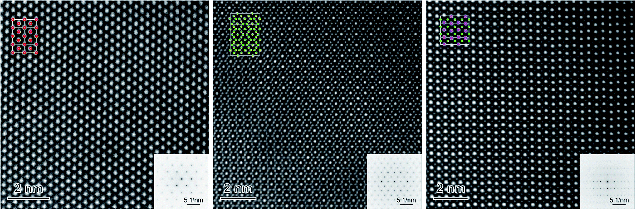 | ||
| Fig. 3 High-resolution HAADF images of single grains of CGO (left), FCO (middle) and GCFCO (right) recorded along the [101], [101] and [110] zone axis, respectively. Upper left/lower right insets are the corresponding structural models/diffraction patterns measured in the TEM mode. Oxygen is not shown. | ||
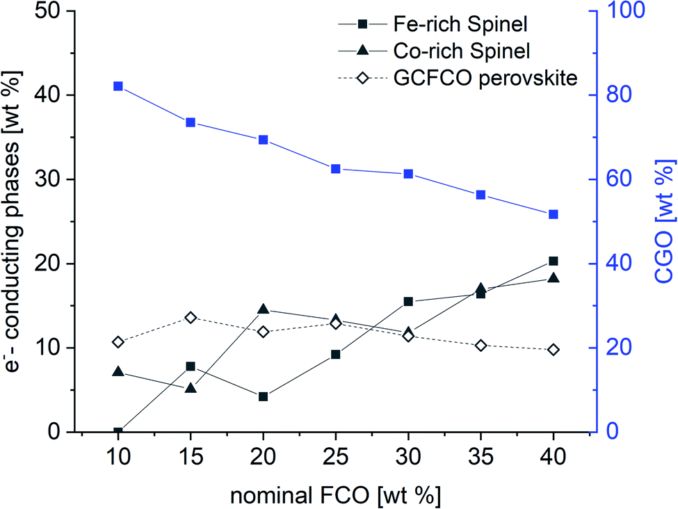 | ||
| Fig. 4 Weight fraction of detected phases in the CGO-FCO composites sintered at 1200 °C for 5 h according to Table 1. | ||
As expected, the CGO weight fraction after sintering steadily decreases with increasing nominal FCO content in the primary powder mixture, whereas the weight fraction of both spinel phases increases. In contrast, the perovskite phase weight fraction remains relatively constant in the range of 11 ± 2% for all composites. However, due to the intense phase interactions the chemical compositions of the respective phases change, which is reflected by a change in lattice parameters in Table 1.
Phase composition
The exact chemical composition of the different phases in the sintered composite is not accessible with methods such as EDS.Therefore, lattice parameters are used to determine the chemical composition of all detected phases after sintering.
| Nominal spinel content [wt%] | x in Co3−xFexO4 Fe-rich spinel | x in Co3−xFexO4 Co-rich spinel | x in Ce2−xGdxO2−d |
|---|---|---|---|
| 10 | — | 0.14 | 0.15 |
| 15 | 0.97 | 0.15 | 0.152 |
| 20 | 0.92 | 0.48 | 0.162 |
| 25 | 1.34 | 0.23 | 0.17 |
| 30 | 1.32 | 0.27 | 0.16 |
| 35 | 1.30 | 0.33 | 0.13 |
| 40 | 1.30 | 0.25 | 0.146 |
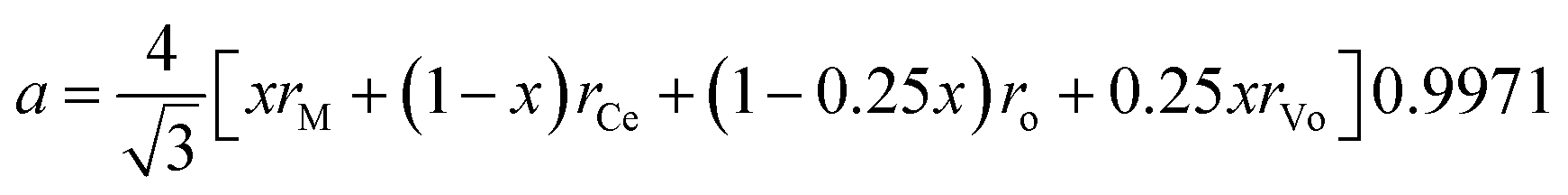
Hong and Virkar31 derived an equation for the lattice parameter of doped ceria considering the ionic radii of the different components
| Nominal spinel content [wt%] | Gd | Ce | Fe | Co |
|---|---|---|---|---|
| 10 | 0.61 | 0.39 | 0.68 | 0.33 |
| 15 | 0.58 | 0.42 | 0.69 | 0.31 |
| 20 | 0.50 | 0.50 | 0.58 | 0.42 |
| 25 | 0.43 | 0.57 | 0.42 | 0.58 |
| 30 | 0.52 | 0.48 | 0.42 | 0.58 |
| 35 | 0.75 | 0.25 | 0.41 | 0.59 |
| 40 | 0.63 | 0.37 | 0.45 | 0.55 |
Composite composition
With knowledge of the composition and weight fraction of the individual phases the actual volume fractions of those coexisting phases can be calculated. The required densities of the different phases are calculated for each composite individually using | (3) |
 | ||
| Fig. 5 Volume fraction of detected phases in the CGO-FCO composites sintered at 1200 °C for 5 h. | ||
Performance
 | ||
| Fig. 6 Ionic conductivity of CGO with 10 and 20 mol% Gd-substitution, respectively. The experimental error is ±5%. | ||
In contrast, the chemical composition of the electronic conducting phases determines their conductivities. Two spinels are synthesized exemplarily, i.e. Fe2CoO4 and FeCo2O4. Fig. 7 shows that the Fe-richer spinel shows lower conductivity. According to Table 2, the maximum Fe-content in the spinel phases is 1.34, well below that of Fe2CoO4 and, thus, the electronic conductivity can be regarded as sufficiently high. In the perovskite system single phase Gd0.85Ce0.15Fe0.75Co0.25O3 (GCFCO) shows very similar conductivity, Fig. 7. Hebb–Wagner measurements of the electronic partial conductivities with variable pO2 of this perovskite (exemplarily shown for pO2 = 0.21 bar as open symbols in Fig. 7) showed a similar dimension like the total conductivities from impedance spectroscopy. In addition, oxygen permeation was negligible, i.e. below the detection limit, revealing that the chosen GCFCO is a pure electronic conductor and does not possess significant oxygen non-stoichiometry, i.e. δ ≈ 0. Moreover, Hebb–Wagner measurements down to pO2 = 10−10 bar did not show any change of transport mechanisms indicating that the non-stoichiometry remains close to zero in that pO2-range.
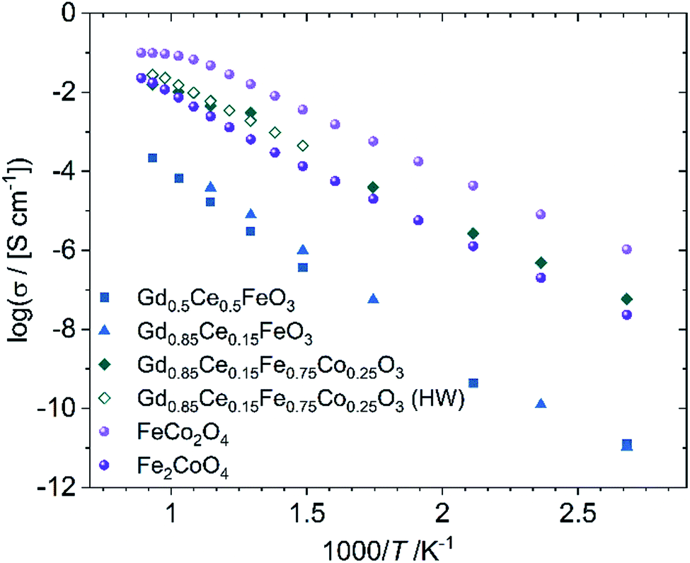 | ||
| Fig. 7 Electronic conductivity of phases identified in the composite. The legend gives nominal compositions, because some samples are not single phase. The experimental error is ±5%. | ||
Co-free perovskites, in contrast, show very low conductivities. However, these materials did not show phase purity, but additional phases such as Gd-doped ceria, magnetite, and Gd3Fe5O12, which are not present in the composites. Apparently, Co substitution on the B-site of GdFeO3 supports perovskite phase formation. Ce substitution on the A-site acts as the donor and enables electronic conductivity. The GdFeO3-based perovskites detected in the composites show Co- and Ce-substitution of 31–59% at the B-site and 25–57% at the A-site, respectively, Table 3. Therefore, those phases are considered as good electronic conductors.
:10 wt% EA = 101 kJ mol−1 indicating a change in the rate limiting process probably due to the lack of electronic conductivity.
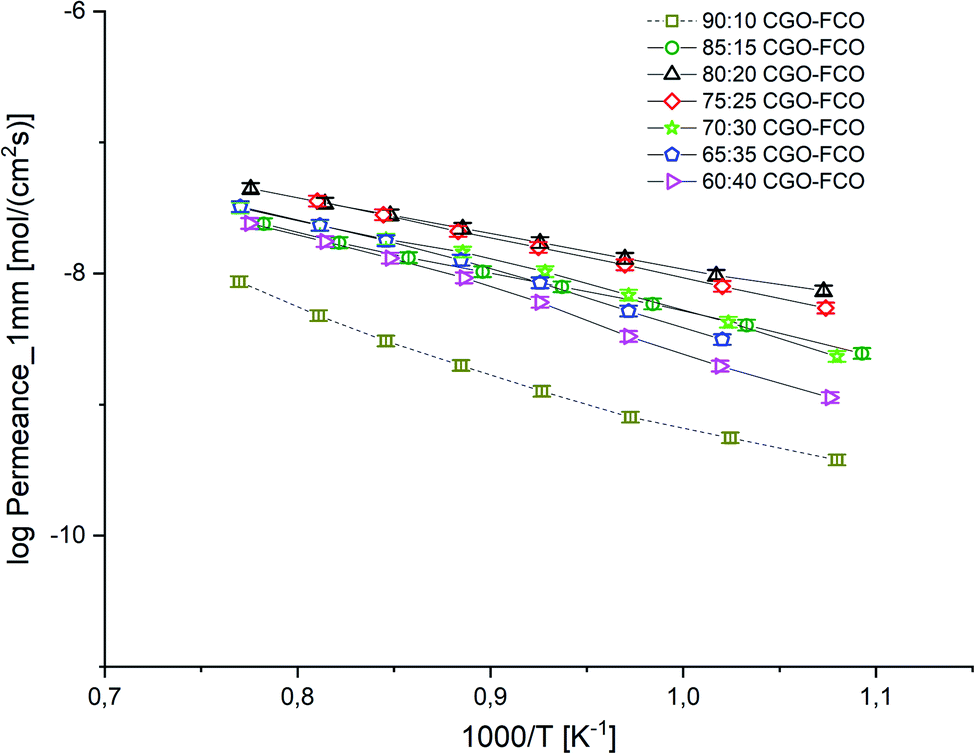 | ||
| Fig. 8 Arrhenius plot of the permeance of CGO-FCO composites normalized to a thickness of 1 mm. Error bars represent ± 10% of the measured values. | ||
Fig. 9 shows a comparison of this work with previously reported data on composites of the same nominal compositions, but differently synthesized, i.e. by the Pechini method,19 a sol–gel technique starting from an aqueous precursor solution. The permeance follows the same systematic process. However, the Pechini synthesized composites show higher performance for low FCO-contents. This might be attributed to the typically finer microstructure with highly homogeneous cation distribution achieved by the sol–gel synthesis. Even if there are some percolating paths, these need to be “strong” enough to ensure sufficient electronic conduction. The comparison of microstructures (Fig. 10) indicates similarly small ceria grains in the sub-micron range and slightly coarser spinel agglomerates for SSRS compared to that obtained by the Pechini method and, thus, no drastic difference. Unfortunately, quantification is not possible due to the low differences in grey scale contrast between the several phases.
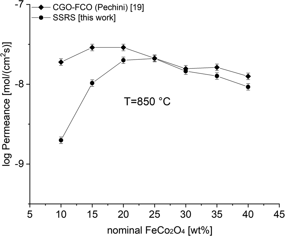 | ||
| Fig. 9 Permeance of differently synthesized composites depending on the nominal FCO-content. Error bars represent ± 10% of the measured values. | ||
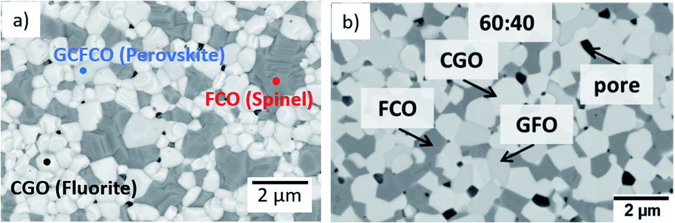 | ||
| Fig. 10 Microstructure of a sintered 60:40 CGO-FCO composite (a) synthesized by SSRS (SEM of surface, this work) and (b) synthesized by the Pechini method previously (SEM cross-section. Reproduced with permission.19 Copyright 2017, Elsevier). | ||
But, as analysed above the phase interactions during sintering lead to an increase in electronic conducting phases. However, this takes place at the expense of the ceria content, i.e. ionic conducting volume, which is rate limiting and thus not desired. Fig. 11 shows the permeance versus the volume fraction of the sum of electronic conducting phases. In comparison to the CGO-FCO series CGO-GCFCO composites were synthesized using commercially available CGO and pre-synthesized Gd0.85Ce0.15Fe0.75Co0.25O3. In this case no phase interactions during sintering are observed and, thus, indeed dual phase membranes are achieved. At low and high e−-conductor content, respectively, the permeance is quite similar. Above 40 vol% an identical behaviour can be expected because the ionic conductivity, i.e. ceria content, is the rate limiting factor. Around 30 vol% of e−-conductor content the SSRS CGO-FCO series shows higher performance over the CGO-GCFCO series. This, again, reveals the importance of the phase distribution, i.e. microstructure, inside the composite close to the percolation threshold. It seems to be even more important than the phase itself, in this case perovskite or spinel, or actually both together, as long as the electronic conductivity of these individual phases is sufficiently high.
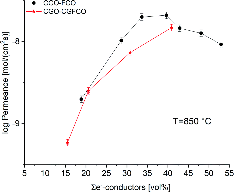 | ||
| Fig. 11 Permeance of CGO-FCO and CGO-GCFCO composites depending on the volume fraction of e−-conducting phases. Error bars represent ±10% of the measured values. | ||
Conclusions
MIEC composites with nominal composition Ce0.8Gd0.2O2−δ (CGO) – FeCo2O4 (FCO) can be successfully synthesized by the cost-efficient solid state reactive sintering (SSRS) technique using commercial powders of CGO as well as Fe2O3 and Co3O4. During sintering several phase interactions occur resulting in a mixture of four phases after sintering, i.e. CGO, two Fe/Co-spinel phases and a GdFeO3-based perovskite. The composition of the individual phases depends on the nominal CGO-FCO ratio defining the mixture of the raw powders. Nevertheless, their functional characteristics, i.e. ionic or electronic conductivity, remain. For the perovskite formation during reactive sintering approx. 5 mol% of Gd is extracted from the initial CGO, which does not affect its ionic conductivity significantly. But, the ceria volume fraction is reduced and, thus the ion conducting pathways. The two spinel phases are in equilibrium according to the Fe3−xCoxO4 phase diagram and provide electronic conductivity, just like the perovskite Gd1−xCexFe1−yCoyO3, which is a donor doped GdFeO3 and, thus, a pure electronic conductor with a similar conductivity to the spinel. Consequently the electronic conducting volume fraction is increased.In MIEC composites typically the ionic conductivity is rate limiting provided that sufficient electronic conduction is achieved, which is a combination of the electronic conductivity of the selected phase(s) and the presence of sufficient percolating paths. This represents a typical optimization task, i.e. maximizing the ionic conducting volume without losing percolation of the electronic conduction.
In comparison to a two phase system without reactive sintering made from pre-synthesized CGO and GCFCO (Gd0.85Ce0.15Fe0.75Co0.25O3) the CGO-FCO SSRS shows higher performance close to 30 vol% of the electronic conducting phases, which is often considered as the percolation threshold. The phase interactions during SSRS obviously help achieving significant percolation of electronic conductors at high ceria content enhancing ambipolar conductivity compared to the CGO-GCFCO series solid state sintered without phase reactions. In the Pechini synthesized CGO-FCO series reported previously comparable phase interactions as in SSRS series occur. Even higher performance at the same nominal composition close to that percolation threshold was found, which might be attributed to the finer particles synthesized by the Pechini method. Moreover, the potential role of grain boundaries needs more attention. These results reveal the importance of tailoring the microstructure of composite membranes by materials engineering, which seems to be even more important compared to the investigation of more and more novel material mixtures.
Summarizing, SSRS of CGO-FCO is an attractive route – even though slightly less performing compared to the Pechini synthesized variant – due to its suitability for industrialization using cheap and abundant oxides. Further developments should concentrate on tailoring the resulting microstructure closing the gap with the Pechini synthesized composites.
Nevertheless, the in situ formed perovskite system (GdCe) (FeCo)O3 represents an interesting alternative candidate as an electronic conductor in ceria-based composite membranes. It is expected to provide higher chemical stability compared to FCO in particular at lower pO2. Moreover, there might be a chance to introduce oxygen non-stoichiometry, which would lead to mixed conductivity supporting ionic transport and facilitating surface exchange not investigated here. Therefore, the GCFCO system should be further investigated.
Author contributions
Liudmila Fischer: investigation & writing – original draft, Kerstin Neuhaus: funding acquisition, investigation, project administration & writing – original draft, Christina Schmidt: investigation & writing – original draft, Ke Ran: investigation & writing – original draft, Patrick Behr: investigation, Stefan Baumann: conceptualization, investigation, funding acquisition & writing – original draft, Joachim Mayer: funding acquisition, & writing – review & editing, Wilhelm A. Meulenberg: resources, supervision & writing – review & editing.Conflicts of interest
There are no conflicts to declare.Acknowledgements
The work is funded by the Deutsche Forschungsgemeinschaft (DFG, German Research Foundation) – 387282673.References
- W. Deibert, M. E. Ivanova, S. Baumann, O. Guillon and W. A. Meulenberg, J. Membr. Sci., 2017, 543, 79–97 CrossRef CAS.
- A. A. Plazaola, A. C. Labella, Y. Liu, N. B. Porras, D. A. P. Tanaka, M. V. S. Annaland and F. Gallucci, Processes, 2019, 7(3), 128 CrossRef CAS.
- J. Sunarso, S. Baumann, J. M. Serra, W. A. Meulenberg, S. Liu, Y. S. Lin and J. C. Diniz da Costa, J. Membr. Sci., 2008, 320, 13–41 CrossRef CAS.
- M. Balaguer, J. García-Fayos, C. Solís and J. M. Serra, Chem. Mater., 2013, 25, 4986–4993 CrossRef CAS.
- H. Cheng, N. Zhang, X. Xiong, X. Lu, H. Zhao, S. Li and Z. Zhou, ACS Sustainable Chem. Eng., 2015, 3, 1982–1992 CrossRef CAS.
- H. Luo, T. Klande, Z. Cao, F. Liang, H. Wang and J. Caro, J. Mater. Chem. A, 2014, 2, 7780–7787 RSC.
- S. Cheng, M. Søgaard, L. Han, W. Zhang, M. Chen, A. Kaiser and P. V. Hendriksen, Chem. Commun., 2015, 51, 7140–7143 RSC.
- J. Garcia-Fayos, M. Balaguer and J. M. Serra, ChemSusChem, 2015, 8, 4242–4249 CrossRef CAS PubMed.
- J. A. Kilner and M. Burriel, Annu. Rev. Mater. Res., 2014, 44, 365–393 CrossRef CAS.
- H. Takamura, T. Kobayashi, T. Kasahara, A. Kamegawa and M. Okada, J. Alloys Compd., 2006, 408–412, 1084–1089 CrossRef CAS.
- H. Luo, H. Jiang, K. Efimov, F. Liang and H. Wang, Ind. Eng. Chem. Res., 2011, 50, 13508–13517 CrossRef CAS.
- W. Fang, F. Liang, Z. Cao, F. Steinbach and A. Feldhoff, Angew. Chem., Int. Ed., 2015, 54, 4847–4850 CrossRef CAS.
- U. Pippardt, J. Böer, C. Bollert, A. Hoffmann, M. Heidenreich, R. Kriegel, M. Schulz and A. Simon, J. Ceram. Sci. Technol., 2014, 5, 309–316 Search PubMed.
- J. Garcia-Fayos, V. B. Vert, M. Balaguer, C. Solís, C. Gaudillere and J. M. Serra, Catal. Today, 2014, 257, 221–228 CrossRef.
- Y. He, L. Shi, F. Wu, W. Xie, S. Wang, D. Yan, P. Liu, M. R. Li, J. Caro and H. Luo, J. Mater. Chem. A, 2017, 6, 84–92 RSC.
- M. Ramasamy, S. Baumann, J. Palisaitis, F. Schulze-Küppers, M. Balaguer, D. Kim, W. A. Meulenberg, J. Mayer, R. Bhave, O. Guillon and M. Bram, J. Am. Ceram. Soc., 2016, 99(1), 349–355 CrossRef CAS.
- Y. Lin, S. Fang, D. Su, K. S. Brinkman and F. Chen, Nat. Commun., 2015, 6, 6824 CrossRef CAS PubMed.
- Z. Zhang, W. Zhou, Y. Chen, D. Chen, J. Chen, S. Liu, W. Jin and Z. Shao, ACS Appl. Mater. Interfaces, 2015, 7, 22918–22926 CrossRef CAS PubMed.
- M. Ramasamy, E. S. Persoon, S. Baumann, M. Schroeder, F. Schulze-Küppers, D. Görtz, R. Bhave, M. Bram and W. A. Meulenberg, J. Membr. Sci., 2017, 544, 278–286 CrossRef CAS.
- F. Zeng, J. Malzbender, S. Baumann, A. Nijmeijer, L. Winnubst, M. Ziegner, O. Guillon, R. Schwaiger and W. A. Meulenberg, J. Eur. Ceram. Soc., 2021, 41, 509–516 CrossRef CAS.
- F. Zeng, J. Malzbender, S. Baumann, M. Krüger, L. Winnubst, O. Guillon and W. A. Meulenberg, J. Eur. Ceram. Soc., 2020, 40, 5646–5652 CrossRef CAS.
- F. Zeng, S. Baumann, J. Malzbender, A. Nijmeijer, L. Winnubst, O. Guillon, R. Schwaiger and W. A. Meulenberg, J. Membr. Sci., 2021, 628, 119248 CrossRef CAS.
- C. D. Lorenz and R. M. Ziff, J. Chem. Phys., 2001, 114, 3659–3661 CrossRef CAS.
- S. C. van der Marck, Phys. Rev. E: Stat. Phys., Plasmas, Fluids, Relat. Interdiscip. Top., 1997, 55, 1514–1517 CrossRef CAS.
- K. Schmale, M. Grünebaum, M. Janssen, S. Baumann, F. Schulze-Küppers and H.-D. Wiemhöfer, Phys. Status Solidi B, 2011, 248(2), 314–322 CrossRef CAS.
- A. Kovács, R. Schierholz and K. Tillmann, J. Large-Scale Res. Facil., 2016, 2, 68–71 CrossRef.
- A. Buchheit, B. Teßmer, K. Ran, J. Mayer, H.-D. Wiemhöfer and K. Neuhaus, ECS J. Solid State Sci. Technol., 2019, 8, P41–P50 CrossRef CAS.
- K. Neuhaus, R. Dolle and H.-D. Wiemhöfer, J. Electrochem. Soc., 2018, 165, F533–F542 CrossRef CAS.
- N. Bahlawane, P. H. T. Ngamou, V. Vannier, T. Kottke, J. Heberle and K. Kohse-Höinghaus, Phys. Chem. Chem. Phys., 2009, 11, 9224–9232 RSC.
- C. Artini, M. Pani, M. M. Carnasciali, J. R. Plaisier and G. A. Costa, Inorg. Chem., 2016, 55, 10567–10579 CrossRef CAS.
- S. J. Hong and A. V. Virkar, J. Am. Ceram. Soc., 1995, 78, 433–439 CrossRef CAS.
| This journal is © The Royal Society of Chemistry 2022 |