
 Open Access Article
 This Open Access Article is licensed under a Creative Commons Attribution-Non Commercial 3.0 Unported Licence
Investigations on sub-structures within cavities of surface imprinted polymers using AFM and PF-QNM†
Martin
Werner
a,
Matthias S.
Glück
a,
Birgit
Bräuer
a,
Alexander
Bismarck
b and
Peter A.
Lieberzeit
 *a
*a
aUniversity of Vienna, Faculty for Chemistry, Department of Physical Chemistry, Währingerstraße 42, 1090 Vienna, Austria. E-mail: Peter.Lieberzeit@univie.ac.at
bUniversity of Vienna, Faculty for Chemistry, Department of Materials Chemistry, Währingerstraße 42, 1090 Vienna, Austria
First published on 23rd February 2022
Abstract
Investigations on lithographically formed cavities of surface-imprinted polymers (SIP) can help to gain deeper understanding on cell recognition with SIPs: it is known that surface topography and biomolecules transferred during surface imprinting contribute to cell adhesion. In this work, SIPs synthesized via two different imprinting techniques, namely stamp imprinting and polymerization of Pickering emulsions, were investigated and compared to each other, using atomic force microscopy (AFM) and Peak Force Quantitative Nano Mechanics (PF-QNM). We focused on SIPs based on poly(styrene-co-divinylbenzene) as model polymer and E. coli as model template for cell imprinting. Both imprinting approaches led to cavities that revealed nanostructures within the imprints. Stamp imprinting cavities feature low surface roughness and channel structures that resemble the negative pattern of the bacteria on the stamp and their filaments, while SIPs synthesized via polymerization of Pickering emulsions reveal globular nanostructures accumulating in the imprints. AFM phase imaging and adhesion mapping using PF-QNM show that these globular structures are remainders of the imprinted E. coli cells, most likely lipopolysaccarides, which is not observable in imprints resulting from stamp imprinting.
Introduction
Since molecularly imprinted polymers (MIPs) evolved from small molecules towards large species including bacteria cells, it has been common sense in the community that this combines two processes: first, imprinting lithography leading to cavities representing the shape of the template in the polymer surface; second, molecular imprinting via assembly of functional monomers around the template leading to the respective pre-organized network of functional groups.1 While substantial research focused on optimizing and evaluating the impact of chemical functionalities,2–4 far fewer work targets the lithographic aspect of surface-imprinted polymers (SIPs), even though it is known that the topography of the surface influences the cell adhesion.5Although the established model proposes monomer assembly around the template as the mechanism to generate complementary chemical information in the polymer, Yongabi et al. demonstrated that cell residues on yeast-imprinted polymer thin films, namely phospholipids, also contribute to cell adhesion.6 They also assume that lipids transferred from bacteria cells on the SIP during the imprinting process helps to explain the notable selectivity of such functional surfaces.7 Therefore, it is important to investigate the cavities on SIPs for the presence of cell components to understand their contribution to cell recognition in such materials.
There are different strategies to fabricate SIPs in various polymer matrices and material types.8 Among those, the most prominent is the production of SIP thin films using micro-contact between a stamp (carrying the template) and a pre-polymerized oligomer solution.9 This stamp imprinting approach turned out to be suitable to generate microorganism sensing layers and has been applied to various transducer types in the field of chemical sensing.10–12
Even though stamp imprinting has allowed for successfully sensing microorganisms in aqueous solutions, there is still an issue: the cavities produced are formed by contact with dry cells immobilized on a substrate, which do not necessarily have exactly the same shape as bacteria in water. To synthesize water-compatible MIPs, the group of L. Ye proposed the polymerization of oil-in-water Pickering emulsions as imprinting strategy.13 It also turned out to be feasible for surface imprinting of bacteria cells.14 Pickering emulsions are stabilized by the ability of certain solid particles or microorganisms to assemble at an oil–water interface.15,16 During microorganism imprinting, the template also functions as the stabilizing particles of the emulsion.14
The cavities resulting from both imprinting strategies can be examined using high-resolution microscopy techniques, such as scanning electron microscopy (SEM) or atomic force microscopy (AFM). While resolution in the micrometre range would in principle suffice to confirm that cavities are present in SIPs, AFM can provide resolution at the atomic scale,17,18 which allows to investigate nano-sized patterning in SIPs more closely. Apart from this, more advanced AFM techniques, such as Peak Force Quantitative Nano Mechanics (PF-QNM), allow mapping of adhesion properties among others.19 Therefore, it should in principle be useful to differentiate between polymer structures and leftovers from incomplete template removal from SIP cavities.
Herein, we present and discuss AFM studies on nanostructures within cavities resulting from both stamp imprinting and polymerization of Pickering emulsions, respectively, using E. coli bacteria as model template and poly(styrene-co-divinylbenzene) as model polymer for both approaches.
Experimental
Chemicals
Styrene, divinylbenzene (DVB), dimethyl sulfoxide (DMSO), (3-aminopropyl)triethoxysilane (APTES), trimethoxyvinylsilane (TMVS) and D-glucose monohydrate were purchased from Merck KGaA, toluene, 2,2′-azoisobutyronitrile (AIBN), 11-mercapto-1-undecanol and yeast extract from Sigma Aldrich, proteose peptone and ethanol from VWR Chemicals, sodium dodecyl sulfate (SDS) from Fluka Chemie AG, disuccinimidyl suberate (DSS) from Acros Organics, acetic acid from Carl Roth GmbH + Co. KG and NaCl from AppliChem GmbH. All chemicals were used as received.Bacteria cultivation
Escherichia coli (ATCC® 9637™) was purchased from American Type Culture Collection. Bacteria were cultivated in lysogeny broth (10 g L−1 proteose peptone, 5 g L−1 yeast extract, 5 g L−1 NaCl, 1 g L−1D-glucose monohydrate) at 37 °C for 24 h. After cultivation bacteria were washed twice with water and directly used for further experiments.Fabrication of bacteria stamp
Clean glass slides were incubated for 5 min in 89 mM APTES solution in toluene to functionalize the glass surface with aminopropyl groups. For covalent crosslinking of bacteria, the slides were further functionalized with DSS solution in DMSO (5 g L−1) for 1.5 h. The functionalized stamps were covered for 2 h with a concentrated E. coli suspension in water. Unbound bacteria were afterwards removed by rinsing with water.Stamp imprinting
Glass slides were treated in oxidative plasma (plasma cleaner Zepto One; Diener electronic) and functionalized with TMVS (4 h incubation in 163 mM TMVS in toluene) to increase the affinity towards poly(styrene-co-divinylbenzene) thin films.Pre-polymer comprising styrene (monomer) and crosslinker DVB (v/v = 50![[thin space (1/6-em)]](https://www.rsc.org/images/entities/char_2009.gif) :50) was synthesized via free radical polymerization (30 min), thermally initiated using 1.8% (w/v) AIBN. A thin film was generated by spin coating the pre-polymer onto the functionalized glass slide.
:50) was synthesized via free radical polymerization (30 min), thermally initiated using 1.8% (w/v) AIBN. A thin film was generated by spin coating the pre-polymer onto the functionalized glass slide.
Patterning of the bacteria cell structures took place by pressing the stamp onto the oligomer thin film. After hardening the polymer over night at 37 °C, the stamp was mechanically removed from the SIP.
SIP-bead synthesis
The oil/monomer phase was prepared by mixing 0.5 mL styrene, 0.5 mL DVB and 1.8% (w/v) AIBN. The monomer mixture was incubated for up to 30 min at 70 °C to initiate free radical polymerization. Freshly cultivated E. coli cells were suspended in 1.2 mL distilled water and mixed with the pre-polymer solution. Vigorous shaking, which was reported as a simple method to produce bacteria-stabilized emulsions,20 was used to emulsify the two phases. The formed pre-polymer droplets were further polymerized at 37 °C. The polymer beads obtained were separated from the aqueous phase and rinsed with water. E. coli cells covering the bead surface were removed by solvent extraction for 5 d in 10% acetic acid + 1% SDS.Atomic force microscopy measurements
AFM measurements took place in air using a Multi Mode 8 AFM with Scan Assist and Peak Force QNM extension (Bruker Corporation). Both, tapping mode and peak force tapping mode (Peak force Quantitative Nano Mechanics, PF-QNM), were used to acquire data.AFM imaging in tapping mode relied on TESPA-V2 tips (Bruker Corporation; k = 42 N m−1; f0 = 320 kHz). RTESP14 tips (VeecoTM; k = 20–80 N m−1; f0 = 284–317 kHz), used for PF-QNM measurements, were functionalized with 11-mercapto-1-undecanol, using an adapted protocol:21 the tips were sputtered with 5 nm Cr layer followed by 30 nm Au. Self-assembly was the result of incubating the gold-covered tips overnight in 3 mM 11-mercapto-1-undecanol solution in ethanol.
Polymer thin films and bacteria stamps were directly measured on their respective carrier glass slides. E. coli cells were immobilized on a glass slide by dropping a suspension of freshly cultivated bacteria in distilled water onto a glass slide and drying at 37 °C. For AFM measurements of beads, the samples were glued to a glass slide using standard nail varnish from a drug store.
For PF-QNM measurements, tips were calibrated using the relative method: the sapphire-12M PF-QNM sample kit standard (Bruker Corporation) served to calibrate deflection sensitivity. The tip radius of the functionalized tips was determined using the PS-film-12M (Bruker Corporation; E = 2.7 GPa) PF-QNM sample kit standard.
Gwyddion 2.50, an open-source software, was used for data processing and evaluation. Curvature was flattened by subtracting a polynomial background (2nd degree) from the images. Colour bars representing the z-range were adjusted to optimize data representation and comparison. Topography profiles were adjusted relative to their first data point. Cell height and imprint depth were determined from profile sections through the features (N = 10 for each surface type). Surface roughness was determined on different spots of the samples via 1 μm line sections (N = 5 for each surface type). Imprint density on SIP-beads was calculated from N = 4 AFM scans of 20 μm × 20 μm. PF-QNM adhesion values were evaluated on different spots of the acquired images with an averaging radius of 5 pixels per spot (N = 5 for each surface type). Two sample Student t-tests were used to evaluate if differences in surface roughness and PF-QNM adhesion values were significant.
Scanning electron microscopy
Scanning electron microscopy (SEM) measurements took place on a Supra 55 VP SEM (Carl Zeiss GmbH). Samples were mounted on carbon adhesive tabs and sputtered with 5 nm gold prior to imaging. Data acquisition took place using an acceleration voltage of 5 kV, a working distance of 12.6–12.9 mm and an aperture size of 30 μm using the secondary electron detector (SE2).Results and discussion
AFM investigations on stamp imprinting
Fig. 1A shows the AFM topography image of a 20 μm × 20 μm section of a bacteria stamp containing immobilized cells on its surface, thus proving appreciable surface coverage of the stamp with bacteriacells. The section profiles over E. coli cells reveal mean cell heights of 200 nm ± 40 nm (Fig. 1B illustrates an example of such a section). Hence, the cells are much wider than high, which clearly indicates that E. coli flattened on the surface during stamp fabrication and thus no longer resemble their typical rod shape in solution. These findings agree well with previous studies reporting flattening of bacteria cells during AFM measurements in air.22,23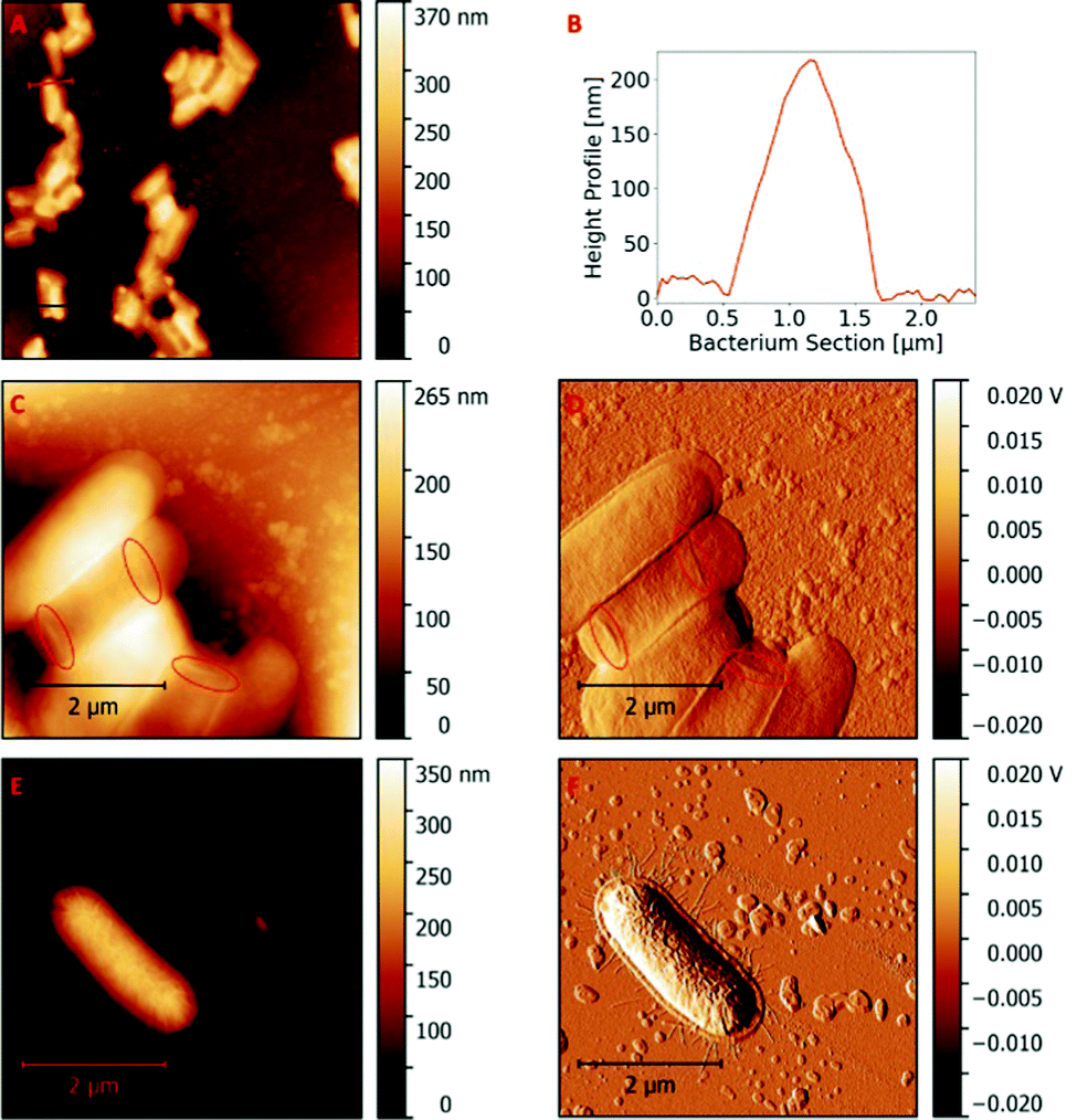 | ||
| Fig. 1 Characteristic AFM scan (20 μm × 20 μm) of a glass stamp containing immobilized E. coli (A); height profile of a selected bacterium immobilized on a glass stamp (B); AFM scan (5 μm × 5 μm) topography image of E. coli immobilized on a glass stamp, revealing nano-sized features marked with red circles (C); AFM scan (5 μm × 5 μm) error image of E. coli immobilized on glass a stamp, revealing nano-sized structures marked with red circles (D); AFM scan (5 μm × 5 μm) topography image of E. coli dried on a glass slide, revealing nano-sized structures, i.e. flagella surrounding the cell (E); AFM scan (5 μm × 5 μm) error image of E. coli dried on a glass slide, revealing nano-sized structures, i.e. flagella surrounding the cell (F). | ||
Closer investigation of the immobilized E. coli cells reveal structural components with dimensions of only a few nanometres. Fig. 1C and D show the topography and error image of a 5 μm × 5 μm AFM scan, respectively, which highlight such fine features on the surfaces of E. coli bacteria. Obviously, one can observe the filamentous structures, which are most probably pili or flagellae of E. coli. Filaments are also the predominant nanostructure observed on E. coli cells, dried on a glass slide (Fig. 1E and F). Flagellae are observable both on the bacteria cell and on the surface immediately surrounding it. Therefore, one can expect that such structures transfer into SIPs.
Fig. 2A sketches the stamp imprinting process leading to patterning poly(styrene-co-divinylbenzene) thin films. AFM imaging reveals rod-shaped cavities covering large parts of the polymer thin film (Fig. 2B). These imprints resemble the structural “negative” of bacteria cells on the stamp: section profiles of bacteria imprints (Fig. 2C) reveal imprint depths of 118 nm ± 15 nm. Thus, imprints were only roughly half as deep as the height of bacteria revealed on the stamps. Therefore, it is most likely that the bacteria cells further flatten during compression in the stamp imprinting process.
 | ||
| Fig. 2 Illustration of the stamp imprinting process. E. coli bacteria covalently immobilized on glass slides are used to pattern cavities in a poly(styrene-co-divinylbenzene) pre-polymer thin film during polymerization (A); AFM scan (20 μm × 20 μm) of E. coli imprints on a polymer thin film (B); depth profile of a selected imprint of the AFM scan (C). | ||
Reducing the AFM scan size from 20 μm × 20 μm to 5 μm × 5 μm (Fig. 3A) increases lateral resolution and reveals sub-structures within the imprints. Numerous indicators show that the observed structures are real and not just measuring artefacts: the features remain visible when reducing the scan size (Fig. 3B) also in the error image (Fig. 3C). Both show filamentous structures within the imprints. They are only a few nanometres deep and resemble the “negative” pattern of pili or flagellae observed on E. coli cell surfaces of the bacteria stamp. Although surface imprinting of biological species with dimensions in the nanometre range has already been reported (e.g. tobacco mosaic virus imprints),24 to the best of our knowledge these data are the first to demonstrate imprints of bacteria substructures within cavities.
 | ||
| Fig. 3 AFM topography image (5 μm × 5 μm) of an E. coli surface SIP (A); AFM scan (2 μm × 2 μm) topography image of an imprint on polymer thin film revealing nano-sized structures (B); AFM scan (5 μm × 5 μm) error image of an imprint on polymer thin film revealing nano-sized structures (C); AFM scan (5 μm × 5 μm) phase shift image of an imprint on polymer thin film (D). | ||
Contrast in the phase shift image can point towards local differences in surface properties.25 However, the phase image of a 5 μm × 5 μm AFM scan (Fig. 3D) does not reveal strong phase shifts within the different features of the scan, which indicates that areas outside and inside the imprints have similar surface properties.
Comparing the surface structure of the SIP thin film to a non-imprinted polymer (NIP) thin film confirms that the observed filamentous nanostructures result from patterning with bacteria cells: one cannot observe such features on NIP thin films (Fig. S2A, ESI†). This further corroborates that nano-sized structures of bacteria cell surfaces generate corresponding features in the respective imprint after stamping. Even though they are of course much larger than functional groups, these findings further strengthen one of the fundamental assumptions of microorganism imprinting: it does not only lead to surface patterning in the micrometre range, but also in (sub-)nanometre dimensions.
The surface roughness in SIP imprints (Rq = 3.3 nm ± 1.0 nm) and their surrounding polymer (Rq = 3.9 nm ± 0.8 nm) do not significantly differ from each other or from the surface roughness on the NIP thin film (Rq = 3.6 nm ± 0.4 nm; see also Fig. S2B, ESI†). However, the surface roughness on bacteria cells (Rq = 3.4 nm ± 1.1 nm) is quite similar to the roughness of the glass slides used for immobilizing them (Rq = 4.6 nm ± 2.4 nm). Hence, one would expect that the SIP imprints and the polymer surfaces surrounding them also reveal similar surface roughnesses.
AFM investigations on SIP beads
E. coli suspensions in water are useful to emulsify an oil/monomer phase in water. During polymerization of such a Pickering emulsion, bacteria attach to and remain in the oil/water interface14 and, therefore, E. coli cells cover the resulting polymer beads (Fig. 4A and B). Fig. 4C shows a 20 μm × 20 μm AFM scan of the bead surface. E. coli cells occupying the polymer surface have a mean cell height of 736 nm ± 103 nm. Fig. 4D shows a typical height profile of such a bacteria cell on the bead surface. As the cells are partly engulfed by the cavities, the overall cell height has to be extended by the imprint depth. With this, the cells were about four times higher than E. coli on the stamp, which is most probably closer to the shape of bacteria in water.23 | ||
| Fig. 4 Illustration of bacteria imprinting by polymerization of o/w Pickering emulsions (A); SEM image of a SIP bead before removal of bacteria (B); AFM scan (20 μm × 20 μm) of E. coli bacteria on a SIP bead (C); height profile of a selected bacterium from the AFM scan (D); SEM image of an entire SIP bead after bacteria removal with solvent extraction in 10% AcOH + 1% SDS (E); AFM scan (20 μm × 20 μm) of bacteria imprints on SIP bead (F); depth profile of a selected bacteria imprint from a SIP bead AFM scan (red) compared to a depth profile of a bacteria imprint on SIP thin film (blue) (G). | ||
Solvent extraction of the bacteria using 10% AcOH + 1% SDS allowed for efficiently removing bacteria cells from bead surfaces. Fig. 4E shows an SEM image of an entire SIP-bead after this step. Fig. 4F shows a corresponding 20 μm × 20 μm AFM scan revealing the imprinted cavities on the surface with an average imprint density of 1.3 × 10⁷ imprints per cm2. The mean imprint depth is 100 nm ± 43 nm. This value corresponds to imprints on polymer thin films; however, for different reasons: Fig. 4G compares typical section profiles of cavities in imprinted thin films and on a bead surface, respectively. Although they have the same depth, the cavity after stamp imprinting is around two times wider. Therefore, bacteria penetrate into the oil phase (i.e. the monomers) only by 12% of their diameter during Pickering emulsification, but retain their rod shape.
Interestingly, imprints on beads and thin films differ with respect to the fine structures on their surfaces, which can be traced back to the imprinting process: Bacteria on SIP-beads feature nano-sized globular structures, as the AFM images in Fig. 5 show. The outer cell membrane of Gram-negative bacteria is largely covered with lipopolysaccharides. It is known that these compounds can form globular structures through aggregation, though such structures are not typically observed on healthy cells, but appear on their surfaces when weakened.26,27 Therefore, it is most likely that the observed globular structures are the result of emulsification, as one cannot observe them on bacteria immobilized on stamps or dried on glass slides (Fig. 1C–F). Due to this alteration in cell surface structure, bacteria on SIP-beads exhibit comparable high surface roughness with an Rq of 14.7 nm ± 3.3 nm.
 | ||
| Fig. 5 AFM scan (5 μm × 5 μm) topography image, revealing globular structures on bacteria cells after bead synthesis (A); corresponding error image (B). | ||
Closer investigation of the cavities after removing the bacteria also reveals similar nano-sized fine structures within imprints, seen in Fig. 6. Obviously, the surfaces inside these cavities are largely covered with globular structures of only a few nanometres in diameter. Although we could also observe such structures on the polymer surface outside the imprints, by far most of them are located inside the imprint cavities. These observations also correlate to surface roughness: Rq inside imprints is 6.1 nm ± 1.6 nm, which is significantly higher than the Rq of 2.4 nm ± 0.3 nm on the polymer surface outside the imprints (t-test; p < 0.01).
 | ||
| Fig. 6 AFM scan (5 μm × 5 μm) topography image of imprints on SIP beads revealing globular structures (A); AFM scan (5 μm × 5 μm) error image (B); AFM scan (5 μm × 5 μm) phase shift (C); AFM scan (3 μm × 3 μm) topography image (D). | ||
Furthermore, the observed fine structures reveal strong contrast in their phase images as shown in Fig. 6C. The areas that they cover, exhibit a positive phase shift compared to others. Phase contrast in AFM imaging can be used to reveal local differences in surface properties or chemical composition.25 Thus, these findings indicate fundamental differences in surface properties between the areas inside and outside the cavities.
When comparing the surface structure of SIP beads synthesized with E. coli as the template to SIP beads synthesized with functionalized silica nanospheres (Fig. S3, ESI†), it is obvious that both feature nano-sized depositions on the polymer surface. This indicates that residues on SIPs are typical for polymerization of Pickering emulsions. Imprinting in such emulsions requires solvent extraction to remove the template from the SIP beads, which is not necessary after stamp imprinting. Therefore, those residues, which do not occur on SIP- or NIP thin films, are possibly the results of solvent extraction to remove the templates.
PF-QNM mapping of adhesion forces
To further investigate differences in surface properties, PF-QNM AFM measurements served to map alterations in adhesion forces on the SIP surfaces. Adhesion mapping with modified tips on polymer beads covered with E. coli demonstrate that the surfaces of bacteria cells are considerably less adhesive than the polymer (Table 1 and Fig. 7A, B). After removal of the bacteria, the surfaces show clear contrast of adhesion forces between the surfaces inside and outside the imprints (Fig. 7C and D): surfaces outside the imprints show four times higher adhesion, than inside (Table 1). This further demonstrates that surface imprinting of bacteria cells indeed did not only produce cavities, but also substantial differences in mechanical properties of the corresponding surface. However, PF-QNM measurements on SIP thin films reveal that not all imprinting techniques necessarily produce such differences in adhesion (Table 1 and Fig. 7E, F). For instance, adhesion force mapping on SIPs produced by stamp imprinting reveals differences confined to the borders of the imprints, which is likely an artefact caused by the abrupt change in surface topography. The results of adhesion mapping on bacteria SIP correlate well with phase contrast images obtained in tapping mode AFM, which also show strong contrast between imprints and surrounding surfaces on SIP-beads synthesized via polymerization of Pickering emulsions (Fig. 6C), but not on the stamp-imprinted thin films (Fig. 3D).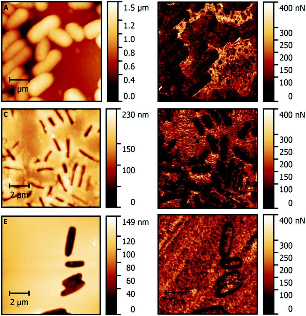 | ||
| Fig. 7 AFM images recorded with an OH-modified tip: topography image (10 μm × 10 μm) of E. coli cells on a bead (A); adhesion image (10 μm × 10 μm) of E. coli cells on a bead (B); topography image (10 μm × 10 μm) of imprints on a SIP bead after solvent extraction in 10% AcOH + 1% SDS (C); AFM adhesion image (10 μm × 10 μm) of imprints on a SIP bead after solvent extraction in 10% AcOH + 1% SDS (D); topography image (10 μm × 10 μm) of stamp imprinted cavities on a thin film (E); adhesion image (10 μm × 10 μm) of stamp imprinted cavities on a thin film (F). | ||
To obtain such images, it is imperative to modify the tip for enhancing interactions between tip and sample surface.21,28 As all samples investigated through PF-QNM were measured on the same day with the same tip, the method proved suitable to reveal relative differences between the samples.
Because only SIP beads feature contrast between imprints and surrounding polymer, one can conclude that the different adhesion forces are the result of the observed globular features accumulating within the imprints. The latter are also the predominant feature on E. coli cell surfaces after polymerization of o/w Pickering emulsions. It has already been reported that outer membrane biomolecules form globular structures when deposited on polystyrene surfaces.29 Therefore, it is valid to assume that removing E. coli cells from SIP-beads by solvent extraction is not complete, resulting in residues remaining inside the cavities on the polymer. As already mentioned, lipid residues on SIPs were reported to contribute to cell adhesion.6 Therefore, the accumulation of lipopolysaccharides could be rather advantageous for such a material as it contributes to cell recognition. However, the results of the stamp imprinting approach reveal that not all SIPs necessarily contain cell residues, as seen on their adhesion maps and on their low surface roughness inside the imprints. In contrast to bacteria removal from SIP beads, which requires solvent extraction, the E. coli cells in stamp imprinting are easily removed without washing, because they are covalently attached to the stamp. Therefore, it is likely that different template removal strategies influence the surface composition of the imprint, i.e. the presence of biomolecules in SIP cavities.
Conclusions
Comparing two different imprinting techniques (stamp imprinting and polymerization of Pickering emulsions) reveals that both approaches result in rod-shaped cavities on the imprinted polymer surfaces. However, the produced imprints distinctly differ from each other: while stamp imprinting leads to cavities comprising smooth surfaces, reflecting the geometry of dried E. coli cells on the stamp and their nano-sized sub-structures, the cavities produced via polymerization of E. coli stabilized o/w emulsions have a rougher surface, dominated by globular structures that influenced the adhesion properties within the imprints. Even though the template and the polymer matrix remain the same, the synthetic pathway to actually generating the lithographic cavities in SIPs strongly influences their appearance. This adds another parameter to optimizing SIPs towards their lithographic features. Furthermore, PF-QNM AFM uncovered differences between the mechanical properties of imprints and their surrounding surfaces on SIP beads, which indicates that surface imprinting does influence the nano-mechanical properties of a polymer surface confirming the fundamental hypothesis of SIPs. Of course, it is of fundamental interest to translate such differences in nanomechanical properties into actual chemical differences. Those comprise for instance the presence and/or distribution of certain functional groups inside and outside cavities. Once this is possible, it opens up the way to characterize both surfaces and templates in a manner to gain deeper understanding of the actual binding mechanisms between the imprinted polymer and its respective target analyte. This may open up the way to gain deeper physicochemical understanding of the actual interactions between cavity and target analyte during rebinding and may help to address a key issue of SIPs, namely their broad affinity distribution, which also should strongly affect reproducibility.Author contributions
Conceptualization: P. A. L., M. W. and A. B.; data curation: M. W. and P. A. L.; formal analysis: M. W.; investigation: M. W., M. S. G. and B. B.; methodology: M. W., M. S. G., B. B. and P. A. L.; project administration: P. A. L.; supervision: P. A. L.; validation: P. A. L., M. W. and M. S. G.; visualization: M. W.; manuscript writing and revision: M. W., P. A. L. and A. B.Conflicts of interest
There are no conflicts to declare.Notes and references
- A. Aherne, C. Alexander, M. J. Payne, N. Perez and E. N. Vulfson, J. Am. Chem. Soc., 1996, 118, 8771–8772 CrossRef CAS.
- K. Ren and R. N. Zare, ACS Nano, 2012, 6, 4314–4318 CrossRef CAS PubMed.
- A. Poller, E. Spieker, P. A. Lieberzeit and C. Preininger, ACS Appl. Mater. Interfaces, 2017, 9, 1129–1135 CrossRef CAS.
- E. Spieker and P. A. Lieberzeit, Proc. Eng., 2016, 168, 561–564 CrossRef CAS.
- L. C. Hsu, J. Fang, D. A. Borca-Tasciuc, R. W. Worobo and C. I. Moraru, Appl. Environ. Microbiol., 2013, 79, 2703–2712 CrossRef CAS PubMed.
- D. Yongabi, M. Khorshid, P. Losada-Pérez, K. Eersels, O. Deschaume, J. D’Haen, C. Bartic, J. Hooyberghs, R. Thoelen, M. Wübbenhorst and P. Wagner, Sens. Actuators, B, 2018, 255, 907–917 CrossRef CAS.
- S. Givanoudi, P. Cornelis, G. Rasschaert, G. Wackers, H. Iken, D. Rolka, D. Yongabi, J. Robbens, M. J. Schöning, M. Heyndrickx and P. Wagner, Sens. Actuators, B, 2021, 332, 1–11 CrossRef.
- J. Pan, W. Chen, Y. Ma and G. Pan, Chem. Soc. Rev., 2018, 47, 5574–5587 RSC.
- F. L. Dickert and O. Hayden, Anal. Chem., 2002, 74, 1302–1306 CrossRef CAS.
- F. L. Dickert, O. Hayden and K. P. Halikias, Analyst, 2001, 126, 766–771 RSC.
- P. Cornelis, S. Givanoudi, D. Yongabi, H. Iken, S. Duwé, O. Deschaume, J. Robbens, P. Dedecker, C. Bartic, M. Wübbenhorst, M. J. Schöning, M. Heyndrickx and P. Wagner, Biosens. Bioelectron., 2019, 136, 97–105 CrossRef CAS PubMed.
- E. Yilmaz, D. Majidi, E. Ozgur and A. Denizli, Sens. Actuators, B, 2015, 209, 714–721 CrossRef CAS.
- X. Shen and L. Ye, Chem. Commun., 2011, 47, 10359–10361 RSC.
- X. Shen, J. Svensson Bonde, T. Kamra, L. Bülow, J. C. Leo, D. Linke and L. Ye, Angew. Chem., Int. Ed., 2014, 53, 10687–10690 CrossRef CAS PubMed.
- Y. Chevalier and M. A. Bolzinger, Colloids Surf., A, 2013, 439, 23–34 CrossRef CAS.
- L. S. Dorobantu, A. K. C. Yeung, J. M. Foght and M. R. Gray, Appl. Environ. Microbiol., 2004, 70, 6333–6336 CrossRef CAS PubMed.
- G. Binnig, C. F. Quate and C. Gerber, Phys. Rev. Lett., 1986, 56, 930–933 CrossRef.
- T. Schimmel, T. Koch, J. Küppers and M. Lux-Steiner, Appl. Phys. A: Mater. Sci. Process., 1999, 68, 399–402 CrossRef CAS.
- A. Kwasniewska, M. Swietlicki, A. Proszynski and G. Gladyszewski, Polymers, 2021, 13, 1–11 Search PubMed.
- P. Wongkongkatep, K. Manopwisedjaroen, P. Tiposoth, S. Archakunakorn, T. Pongtharangkul, M. Suphantharika, K. Honda, I. Hamachi and J. Wongkongkatep, Langmuir, 2012, 28, 5729–5736 CrossRef CAS.
- D. Alsteens, V. Dupres, S. Yunus, J. P. Latgé, J. J. Heinisch and Y. F. Dufrêne, Langmuir, 2012, 28, 16738–16744 CrossRef CAS PubMed.
- A. V. Bolshakova, O. I. Kiselyova, A. S. Filonov, O. Y. Frolova, Y. L. Lyubchenko and I. V. Yaminsky, Ultramicroscopy, 2001, 86, 121–128 CrossRef CAS.
- M. Mathelié-Guinlet, C. Grauby-Heywang, A. Martin, H. Février, F. Moroté, A. Vilquin, L. Béven, M. Delville and T. Cohen-Bouhacina, J. Colloid Interface Sci., 2018, 529, 53–64 CrossRef PubMed.
- F. L. Dickert, O. Hayden, R. Bindeus, K. J. Mann, D. Blaas and E. Waigmann, Anal. Bioanal. Chem., 2004, 378, 1929–1934 CrossRef CAS.
- D. Raghavan, X. Gu, T. Nguyen, M. VanLandingham and A. Karim, Macromolecules, 2000, 33, 2573–2583 CrossRef CAS.
- L. P. Kotra, D. Golemi, N. A. Amro, G. Y. Liu and S. Mobashery, J. Am. Chem. Soc., 1999, 121, 8707–8711 CrossRef CAS.
- I. Gammoudi, M. Mathelie-guinlet, F. Morote, L. Beven, D. Moynet, C. Grauby-heywang and T. Cohen-bouhacina, Colloids Surf., B, 2016, 141, 355–364 CrossRef CAS PubMed.
- C. D. Frisbie, L. F. Rozsnyai, A. Noy, M. S. Wrighton and M. Lieber, Science, 1994, 265, 2071–2074 CrossRef CAS.
- Q. Lu, J. Wang, A. Faghihnejad, H. Zeng and Y. Liu, Soft Matter, 2011, 7, 9366–9379 RSC.
Footnote |
| † Electronic supplementary information (ESI) available. See DOI: 10.1039/d2sm00137c |
| This journal is © The Royal Society of Chemistry 2022 |