
 Open Access Article
 This Open Access Article is licensed under a
 Creative Commons Attribution 3.0 Unported Licence
A BODIPY small molecule as hole transporting material for efficient perovskite solar cells†
John Marques
Dos Santos‡
 a,
Lethy Krishnan
Jagadamma‡
b,
Michele
Cariello
a,
Ifor D. W.
Samuel
*b and
Graeme
Cooke
*a
a,
Lethy Krishnan
Jagadamma‡
b,
Michele
Cariello
a,
Ifor D. W.
Samuel
*b and
Graeme
Cooke
*a
aSchool of Chemistry, University of Glasgow, Glasgow, G12 8QQ, UK. E-mail: Graeme.Cooke@glasgow.ac.uk
bOrganic Semiconductor Centre, SUPA, School of Physics and Astronomy, University of St. Andrews, St. Andrews, Fife, KY16 9SS, UK. E-mail: idws@st-andrews.ac.uk
First published on 30th August 2022
Abstract
BODIPY-based materials are well known for their outstanding chemical and photo-stability as well as their ease of synthesis and tunability of their frontier molecular orbitals. These are attractive features for hole transporting materials (HTMs) for perovskite solar cells (PSCs) that could help improve device stability and cost. In this paper, we report the straightforward synthesis of a new BODIPY small molecule, PTZ-PTZ-BDP, functionalised with phenothiazine moieties in both the meso and α positions giving rise to a Y-shaped structure. As estimated by DFT calculations, and confirmed by electrochemical and ambient photoemission spectroscopy studies, PTZ-PTZ-BDP presents appropriate energy levels suitable for its use as a HTM in PSCs. Electrochemical measurements also reveal several redox processes with excellent reversibility. Systematic evaluation of its performance as HTM in n–i–p PSC with and without dopants was conducted and the device parameters compared with commonly used HTMs of spiro-OMeTAD and PTAA. The CH3NH3PbI3 based PSCs incorporating simple solution processed PTZ-PTZ-BDP as HTM demonstrated a champion power conversion efficiency of 14.6%, matched in performance and shelf-life stability to complex and expensive state-of-the-art HTMs, showing that BODIPY based HTMs are a promising direction for perovskite solar cells.
Introduction
Perovskite solar cells (PSCs) emerged in recent years as a promising photovoltaic technology that is developing rapidly in terms of device architecture and power conversion efficiency (PCE).1,2 From an initial 3.8% PCE in 2009,3 they are currently certified with efficiencies surpassing 25%,1,4–7 and the initial phase of industrialisation is expected soon.8–14 The narrow and tuneable band-gaps, high extinction coefficients in the UV-vis and near-infrared region, small exciton binding energy, high crystallinity and charge mobility, and exceptionally long carrier life time, along with the ambipolar charge transport ability, are some of the remarkable features of these organic–inorganic hybrid materials.10,12,15 In such cells, the perovskite material, with a general formula APbX3 [A = methylammonium (CH3NH3)+ or formamidinium (CH3(NH2)2+); and X = Cl−, Br−, I− or mixed halides], is usually sandwiched between an electron transport layer (ETL) and a hole transport layer (HTL),16 in which the latter plays a crucial role in the stability and efficiency of the device.11 The high power conversion efficiency of perovskite based solar cells is a result of the excellent optoelectronic properties of both the perovskite photoactive layer and the charge selective layers. In spite of the fact that PSCs have experienced tremendous progress, long term stability is an important goal and continues to challenge the academic community and the industry.7 Due to high degradability via exposure to humidity, temperature, oxygen, high pressure and even UV light,17–22 PSCs still show considerable limitations that prevent their uptake in the market.23,24To obtain high PCE and stability with perovskite based solar cells, each layer has to fulfil several functions. The charge selective layers should be transparent, possess proper energetic alignment with the HOMO/LUMO of the perovskites to ensure charge selectivity and blocking of the opposite carrier, high charge carrier mobility, easy processability and low cost. Two device architectures are widely used: the n–i–p structure in which holes are extracted through a metal contact on the top of the device, and the p–i–n structure in which they are extracted through the bottom of the device which consists of ITO on a glass substrate. In the former case, the HTM lies between the air outside the device and the perovskite active layer. Hence in addition to its electronic properties it also plays a role as a protecting layer against air, moisture and diffusion of the metal electrode into the perovskite material, thereby reducing degradation.18 It is desirable for HTMs to possess hydrophobicity, a LUMO level located above the conduction band of the perovskite used and high chemical and photo-stability25
A very widely used HTM in n–i–p perovskite solar cells is spiro-OMeTAD.25–27 It remains the most dominant HTM in n–i–p PSCs due to its solution processability, amorphous nature, and appropriate energy levels to match with the hybrid perovskites. Despite these advantages, to achieve good conductivity and performance, spiro-OMeTAD needs dopants such as the bis(trifluoromethane)sulfonimide lithium salt (LiTFSI),28,29 4-tert butylpyridine and (tBP)30 and tris(2-(1H-pyrazol-1-yl)-4-tert-butylpyridine)cobalt(III) tri[bis(trifluoromethane)sulfonimide] (FK209).31 LiTFSI for instance, is a p-type dopant used to improve the conductivity of HTMs: while the lithium ions facilitate the oxidation of the HTMs, the TFS− counter-ions stabilize the oxidized HTM species.28 Other important issues are pinhole formation which accelerates the device degradation by moisture and oxygen diffusion to the perovskite active layer and temperature induced changes in the transport properties even at 50 °C. Moreover spiro-OMeTAD synthesis is lengthy, low yielding (∼40%) and for purification, costly sublimation is required, making it an expensive (∼470 USD per gram) material choice.25,32 These issues make spiro-OMeTAD a less attractive HTM for industrial scale fabrication of n–i–p solar cells despite their high efficiency.
Several polymeric materials such as P3HT, poly-TPD, PTAA have been investigated to replace spiro-OMeTAD.6,7,25,33–35 Among these, PTAA and poly-TPD are also expensive HTMs (∼500 USD for 1 g of poly-TPD and 2000 USD for 1 g of PTAA) which presents a barrier to large scale manufacture. Some of the most promising families of small molecules exploited as HTMs in the literature include spiro-like compounds,25 star-shaped compounds,36,37 carbocyclic cores,38,39 nitrogen40 or sulphur41 containing central scaffolds and oligomeric-like molecules.5–7
Materials that naturally possess good chemical and photo stability and are easily tuneable in their frontier orbitals energy levels are attractive for generating efficient HTMs in perovskite solar cells.40,42–44 It is rather surprising that the use of BODIPYs is relatively scarce as HTMs in PSC,45–47 especially considering their typically high photochemical and electrochemical stability, often high hole mobility,48 and multiple stable redox processes.49–53 They have been successfully applied in optoelectronic applications,54 generating efficient dye-sensitised solar55 cells and bulk-heterojunction solar cells.56,57 Despite the fact that some BODIPY synthesis can be relatively low in yield, they often benefit from short synthetic routes58,59 and relatively easy one-pot type procedures,60–62 which can, in turn, compensate in terms of cost. From the best of our knowledge, there has been only one report of them directly applied as HTMs in PSCs: the polymeric BODIPY-based materials by Keyong et al.45 (showing 16.02% for the best cell with exceptional stability and non-doped). Hence, further investigation of the potential of this class of materials is needed, especially as small molecules. In this contribution, a symmetric BODIPY-based material, named PTZ-PTZ-BDP, was designed, synthesised and its photophysical and electrochemical properties were investigated (Fig. 1). The compound features a BODIPY core and phenothiazine branches, giving rise to a Y-like structure. The investigation showed promising characteristics including multiple redox waves with reversible character. PTZ-PTZ-BDP was then incorporated as HTM in a typical n–i–p and p–i–n PSCs and its performance was systematically studied and compared to that of existing HTMs of PTAA and spiro-OMeTAD.
 | ||
| Fig. 1 Chemical structure of PTZ-PTZ-BDP. | ||
Results and discussion
Synthesis
PTZ-PTZ-BDP was synthesized following a well-established procedure,63 that encompasses a Knoevenagel type condensation of the meso-functionalized BODIPY53 with a phenothiazine carbaldehyde derivative. Synthetic details and structure verification are given in the ESI.†Optical and electrochemical properties
The UV-vis absorption spectrum of PTZ-PTZ-BDP was recorded in dichloromethane solution (1 × 10⁻⁵ M) and is provided in Fig. 2. The spectrum features maximum absorption (λmax) at 689 nm (data available in Table 1), which likely originates from intramolecular charge transfer (ICT) between phenothiazine units and the BODIPY core.53 Another absorption peak is seen at 333 nm and can be ascribed to π–π* transition of the conjugated backbone. As already reported for BODIPY dyes of this kind,53 the functionalisation on the α positions is responsible for the broad absorption spectrum observed. PTZ-PTZ-BDP shows an extinction coefficient value (εmax) of c.a. 6.4 × 10⁴ M−1 cm−1, and an optical bandgap (Eopt) of 1.59 eV. In thin film form the absorption spectra profile is preserved but a redshift and broadening of the peaks are observed. Similar effects have been previously observed in comparing the absorption spectra of small molecules in solution and thin film.64,65 The red shift can arise from increased electron delocalisation (possibly including contributions from aggregation or π-stacking),65,66 whilst the broadening can arise from a wider range of conformations in the film.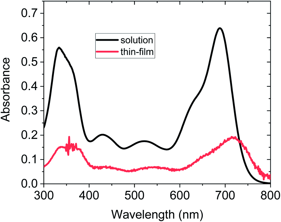 | ||
| Fig. 2 (a) UV-vis spectra of PTZ-PTZ-BDP solution recorded in DCM (1 × 10⁻⁵ M) (b) UV-vis spectra of PTZ-PTZ-BDP in thin film form (∼30 nm thickness). | ||
| λ max (nm) | λ max (nm) | ε max (M−1 cm−1) | λ onset (nm) | E opt (eV) | E 1/2 ox (V) | E 1/2 red (V) | IPe (eV) | EAf (eV) | E fund (eV) |
|---|---|---|---|---|---|---|---|---|---|
| a Measured in dichloromethane (1 × 10⁻⁵ M). b Measured in thin film. c Calculated using the formula Eopt = 1240/λonset. d Measured in dichloromethane (5 × 10⁻⁴ M) and calibrated versus the ferrocene/ferrocenium (Fc/Fc+) redox couple. e Calculated using the formula IP = −[Eox + 4.8] eV. f Calculated using the formula EA = −[Ered + 4.8] eV. g Calculated using the formula Efund = |IP − EA| eV. | |||||||||
| 689 | 6.4 × 10⁴ | 779 | 1.59 | 0.21 | −1.42 | −5.0 | −3.4 | 1.6 | |
Cyclic voltammetry (CV) measurements [recorded in DCM 5 × 10⁻⁴ M, calibrated versus the ferrocene/ferrocenium (Fc/Fc+) redox couple], reveal multiple oxidation waves and one reduction wave for PTZ-PTZ-BDP (see Fig. 3). Reversible character is indicated by the CV waveform during the oxidation and the reduction processes. This suggests that PTZ-PTZ-BDP can undergo several oxidation processes while exhibiting good stability, which is a valuable characteristic and accounts for the electrochemical stability of optoelectronic devices featuring this unit.67,68 This is especially true for PSC, where the HTM has to undergo rapid oxidation processes while maintaining reasonable stability.28,69 The oxidation waves overlap in the CV, therefore square wave voltammetry (SW) measurements were carried out and the voltammogram is provided in Fig. S4 (ESI†); where one can clearly see four oxidation and one reduction peaks. The values of first oxidation potential (E1/2 ox) and first reduction potential (E1/2 red), taken from the SW measurements, were used to estimate the respective ionization potential (IP) and electron affinity (EA). Based on the measurements, PTZ-PTZ-BDP has an IP of −5.0 eV and an EA of −3.4 eV, culminating in a fundamental-gap (Efund) of 1.6 eV. This ionization potential closely matches that of spiro-OMeTAD in its commonly used configuration (doped with LiTFSi and tBP and exposed to air) [see Fig. 3(b)].25
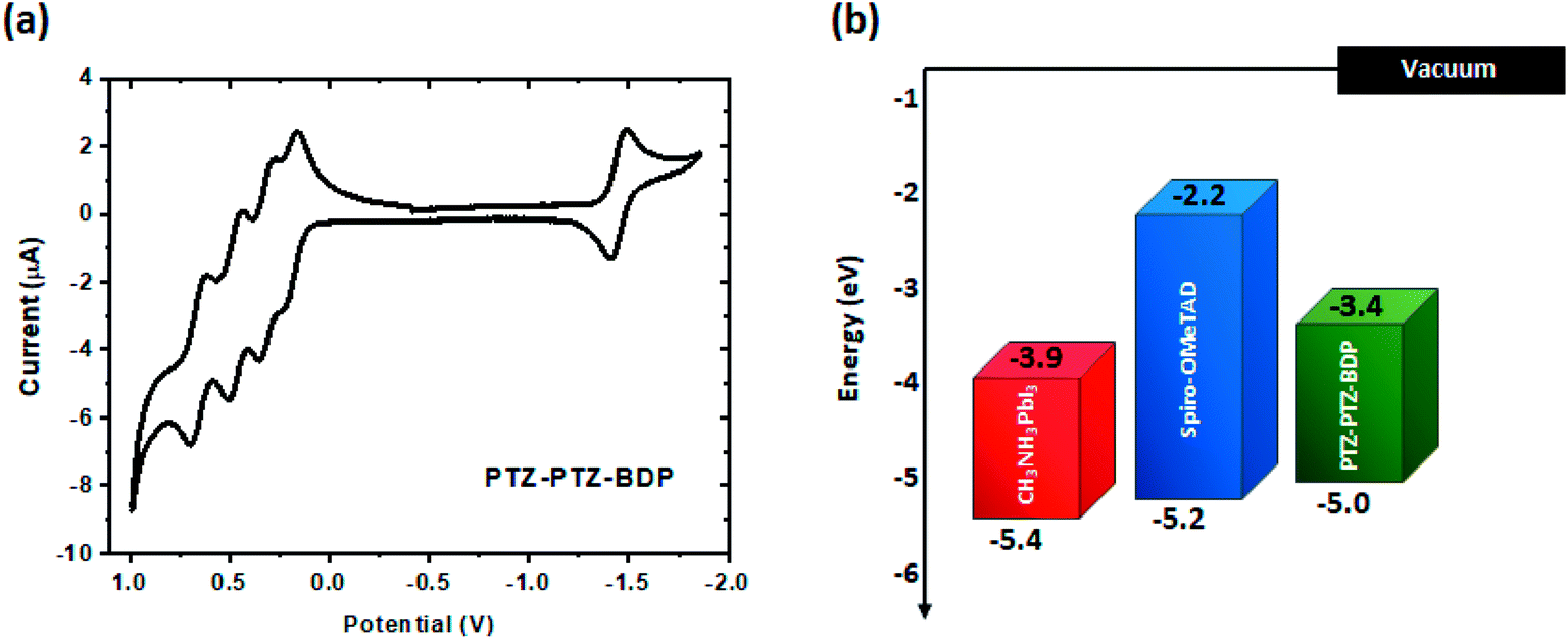 | ||
| Fig. 3 (a) Cyclic voltammetry of PTZ-PTZ-BDP, recorded in DCM (5 × 10⁻⁴ M), calibrated versus the ferrocene/ferrocenium (Fc/Fc+) redox couple, using TBA·PF6 as electrolyte, a 1.6 mm diameter platinum working electrode, a platinum wire counter electrode and a silver wire pseudo-reference electrode. (b) Energy level diagram of PTZ-PTZ-BDP and spiro-OMeTAD;25 for reference, the valence and conduction bands of CH3NH3PbI3 are also included.38 | ||
DFT modelling
Density functional theory (DFT) calculations at the B3LYP/6-311G(d,p) level were carried out in order to better understand the electronic properties of PTZ-PTZ-BDP, and in particular, provide the HOMO and the LUMO energy levels.70 The optimised structure and the HOMO and LUMO maps are provided in Fig. 4. An angle of 88° for the meso-phenothiazine moiety relative to the BODIPY core was revealed by the calculation. On the other hand, a small angle of c.a. 2.7° for the styryl phenothiazine units and the core was observed, giving rise to the Y-shaped structure. Due to their butterfly conformation, the phenothiazine moieties face in opposite directions to circumvent steric hindrance. These values match those of other reported compounds of the same kind.53,71 The HOMO distribution is primarily located on the styryl groups with considerable extension to the core, whereas the LUMO is confined to the π-framework of the BODIPY core and slightly extends to the styryl groups. The meso-substituent is usually absent in frontier orbital electronic distribution due to the high dihedral angle typically observed,53,72 which is exacerbated by the presence of methyl groups in the positions 1 and 7, which is also observed here. The HOMO energy level was estimated as −4.73 eV and the LUMO as −2.67 by the calculation (see Table S1†). | ||
| Fig. 4 Schematic representation of optimised structure [front (a) and side (b) views] and HOMO and LUMO maps (c) of PTZ-PTZ-BDP computed at the B3LYP level of theory and the 6-311G(d,p) basis set. | ||
Photovoltaic properties
The HOMO level of the pristine PTZ-PTZ-BDP thin film and its comparison with the photoactive layer of MAPbI3, PTAA and spiro-OMeTAD measured using ambient photoemission spectroscopy is shown in Fig. 5(a). Without any dopants added, the HOMO level of PTZ-PTZ-BDP is found to be closer to MAPbI3 than that of PTAA and spiro-OMeTAD which could be beneficial for the charge transfer processes at the HTM/perovskite buried interface. The p-type nature of the PTZ-PTZ-BDP along with that of PTAA and spiro-OMeTAD is demonstrated through the work function (WF) measurement using the Kelvin probe method and is given in Fig. 5(b). The hole mobility of the PTZ-PTZ-BDP thin films was estimated using the space charge limited current (SCLC) method and the corresponding J–V curve is shown in Fig. 5(c). The obtained hole mobility is (2.02 ± 0.94) × 10−5 cm2 V−1 s−1 and is comparable to that of the hole mobilities previously reported for pristine PTAA (3–4 × 10⁻⁵ cm2 V−1 s−1) and spiro-OMeTAD (1.67 × 10⁻⁵ cm2 V−1 s−1).73–75 With these promising optical and electrical properties of the PTZ-PTZ-BDP films, their hole extraction properties were tested in perovskite photovoltaic devices using MAPbI3 as the photoactive layer.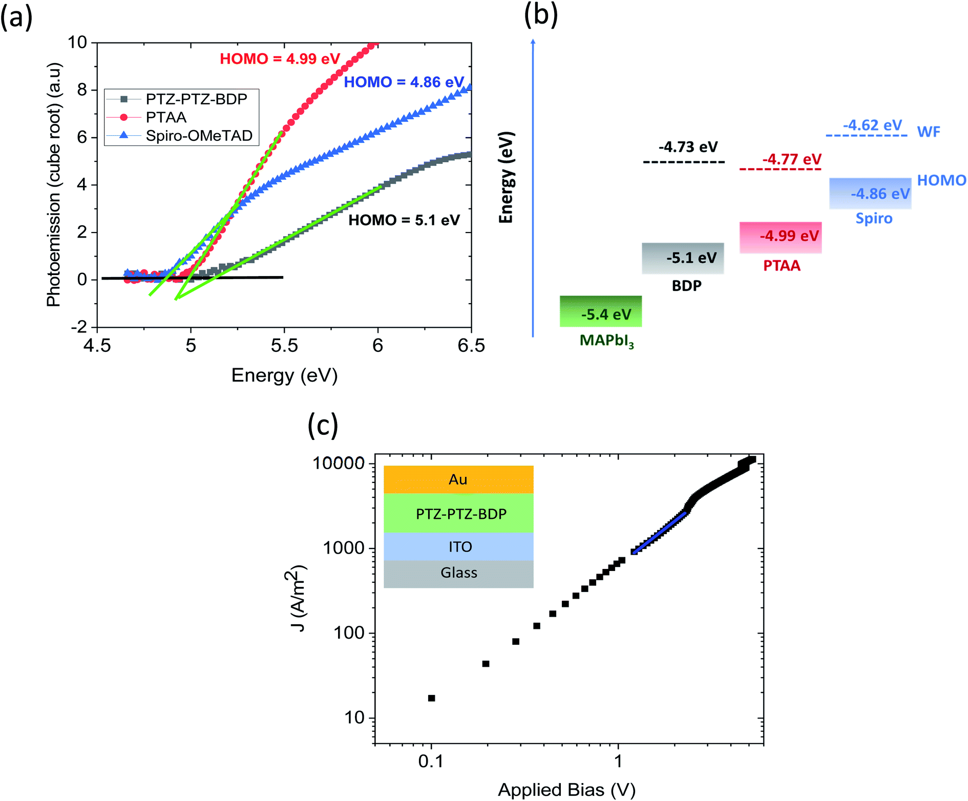 | ||
| Fig. 5 (a) Ambient photoemission spectra of PTZ-PTZ-BDP, PTAA and spiro-OMeTAD thin films (b) energy level diagram showing the HOMO level of MAPbI3 compared to that of PTZ-PTZ-BDP, PTAA and spiro-OMeTAD. The work function (WF) values are shown in dotted lines (c) current density (J)–voltage (V) curves of the hole only devices for the pristine PTZ-PTZ-BDP films. The inset shows the device architecture used for obtaining the current–voltage data. | ||
Fig. 6(a) shows the n–i–p device architecture used in the present study. The perovskite solar cells were fabricated with and without dopants for the PTZ-PTZ-BDP and the photovoltaic performance is compared with two of the most widely used HTMs PTAA and spiro-OMeTAD. Fig. 6(b) and (c) show the distribution of the PCE and photovoltaic performance parameters of the perovskite solar cells using PTAA and PTZ-PTZ-BDP as the HTMs with and without LiTFSI and tBP as dopants. The corresponding J–V characteristics are shown in Fig. S5(a), (b) and S6(a), (b).† Without any dopants, the PTAA based devices show higher average power conversion efficiency of ∼8% (best PCE 9.3%), compared to PTZ-PTZ-BDP devices with average PCE of 6%. As shown in Table S2,†PTZ-PTZ-BDP HTM based devices have slightly lower Voc (0.76 V vs. 0.84 V) and FF (50% vs. 55%) and the yield was also lower compared to PTAA HTM based devices. Upon adding LiTFSI and tBP dopants to the HTM in the molar ratio of 1![[thin space (1/6-em)]](https://www.rsc.org/images/entities/char_2009.gif) :0.082:0.39 respectively, the average power conversion efficiency of both the PTZ-PTZ-BDP and PTAA based devices increased to ∼10%, with the champion device efficiency ∼12%. Previously it has been shown that when PTAA is used as HTM in the n–i–p configuration, this particular dopant concentration gives the best device performance.76 We note that higher efficiency (∼17%) has been reported in the literature, but the number obtained here is typical of our lab and still enables comparison with other HTLs.77 As shown in Table S3,† for PTZ-PTZ-BDP based devices the Voc increased to 0.903 V and FF improved to 55%. The comparison of the EQE spectra of the devices with PTAA HTM is shown in Fig. 6(d). For all the perovskite solar cells described so far, the thickness of the PTZ-PTZ-BDP films were maintained at ∼26 nm. This thickness is closely matching with that of the commonly used PTAA HTM layer thickness of ∼30–40 nm in the n–i–p device architecture.76,78
:0.082:0.39 respectively, the average power conversion efficiency of both the PTZ-PTZ-BDP and PTAA based devices increased to ∼10%, with the champion device efficiency ∼12%. Previously it has been shown that when PTAA is used as HTM in the n–i–p configuration, this particular dopant concentration gives the best device performance.76 We note that higher efficiency (∼17%) has been reported in the literature, but the number obtained here is typical of our lab and still enables comparison with other HTLs.77 As shown in Table S3,† for PTZ-PTZ-BDP based devices the Voc increased to 0.903 V and FF improved to 55%. The comparison of the EQE spectra of the devices with PTAA HTM is shown in Fig. 6(d). For all the perovskite solar cells described so far, the thickness of the PTZ-PTZ-BDP films were maintained at ∼26 nm. This thickness is closely matching with that of the commonly used PTAA HTM layer thickness of ∼30–40 nm in the n–i–p device architecture.76,78
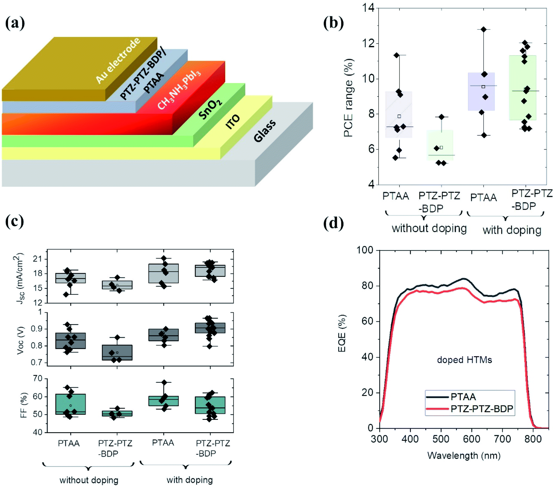 | ||
| Fig. 6 (a) The n–i–p device architecture used for the solar cell device fabrication (b) comparison of the power conversion efficiency (PCE) of the solar cells with the HTMs of PTAA and PTZ-PTZ-BDP with and without doping (c) comparison of the photovoltaic performance parameters of the PTAA and PTZ-PTZ-BDP based devices with and without doping (d) EQE spectra of the n–i–p solar cells with the doped PTAA and PTZ-PTZ-BDP as HTMs. The molar concentration ratio of HTM:LiTFSI:tBP was 1:0.082:0.39. | ||
By keeping the thickness of the HTM layer as 26 nm, the doping concentration of the LiTFSI and tBP were then increased to 1:0.164:0.78. The performance parameters are shown in Table S4.† The average efficiency is increased to 10.6%, (champion cell PCE of 12.8%) with the corresponding improvement of average Voc (0.96) and FF (62%). This improvement in Voc can be due to the work function modification of the HTM and its better alignment with the photoactive blend of CH3NH3PbI3. The improvement in FF suggests that the mobility of the charge carriers in the HTM has been improved.79 To investigate the role of PTZ-PTZ-BDP HTM thickness on the device performance, two other thicknesses (one higher and lower) of the HTM were also considered keeping the doping ratio of LiTFSI and tBP as to 1:0.164:0.78. The photovoltaic performance parameters of the devices are given in Fig. 7(a) and (b). When the thickness was increased to 35 nm the average PCE increased to 12.4% with the champion cell efficiency increased to 14.6%. This improvement is mainly due to the increased Voc to 1.02 V and the FF to 67%. This champion PCE is slightly higher than that obtained using spiro-OMeTAD as the HTM (FS 12.5% and RS 13.7%) as shown in Fig. S7.† Reducing the PTZ-PTZ-BDP thickness from 26 nm to 22 nm has not much influence on the PCE and photovoltaic performance parameters. Fig. 7(c) shows the J–V characteristics of the best performing solar cell device with the doped PTZ-PTZ-BDP as the HTM. The EQE spectra of the best performing solar cell and the integrated Jsc are shown in Fig. 7(d).
 | ||
| Fig. 7 (a) Comparison of the power conversion efficiency as a function of different thickness of PTZ-PTZ-BDP thin films (b) comparison of the photovoltaic performance parameters as a function of thickness (c) J–V characteristics of the champion solar cells with PTZ-PTZ-BDP as HTM. FS stands for forward scan and RS stands for reverse scan (d) EQE spectra and the integrated Jsc of the champion solar cells with PTZ-PTZ-BDP as HTM. | ||
Motivated by the high efficiency of the PTZ-PTZ-BDP HTM based n–i–p perovskite solar cells, their hole extraction property was characterised in p–i–n device architecture as well. In this architecture, the perovskite layer is deposited from solution in DMF and DMSO onto the HTM. We therefore tested the compatibility of PTZ-PTZ-BDP thin films with DMF and DMSO. We found that the PTZ-PTZ-BDP resisted the solvents well (i.e. was not dissolved by them), but they had difficulty wetting the HTM layer. To overcome this a thin layer (∼2 nm) of PFN-P1 polyelectrolyte was deposited on the HTM to improve its wettability. This property is similar to the existing HTMs like PTAA and poly TPD where this polyelectrolyte processing has shown to improve the solar cell device yield.
The p–i–n device architecture used for the fabrication of the solar cells is shown in Fig. 8(a). The solar cells with PFN-P1 alone as HTM showed only an average PCE of ∼3.5%. However, when the HTM layer is modified with PTZ-PTZ-BDP + PFN-P1, the average power conversion efficiency improved to ∼5.2%. The J–V characteristics of the best solar cells in p–i–n configuration is shown in Fig. 8(b) along with the control device's characteristics. The EQE spectrum is shown in Fig. 8(c). The corresponding photovoltaic performance parameters are shown in Table S5.† The J–V characteristics and the EQE spectra show that, more optimisation are needed to improve the PTZ-PTZ-BDP performance in p–i–n configuration.
 | ||
| Fig. 8 (a) Solar cell configuration for the p–i–n solar cells (b) J–V characteristics of the PTZ-PTZ-BDP + PFN-P1 as HTM and PFN-PI alone as HTM. FS stands for forward scan and RS stands for reverse scan (c) the EQE of the champion p–i–n device using PTZ-PTZ-BDP as the HTM. | ||
The shelf-life stability of the PTZ-PTZ-BDP HTM based n–i–p MAPbI3 solar cell devices was tested for the period of 6 months. The non-encapsulated cells was stored inside a desiccator under near ambient air conditions of 30% relative humidity (measured using HTC-1 thermo-hygrometer) and at a room temperature of 22 °C. The devices retained 80% of their initial PCE, with the drop mainly for the Voc. However, these devices showed higher hysteresis effect upon aging. Table S6† shows the comparison of the best performing devices while they were fresh and after aging of six months. The shelf-life stability of the spiro-MeOTAD HTM based n–i–p MAPbI3 solar cell devices are also shown in Table S6.† Compared to the PTZ-PTZ-BDP HTM, the spiro-MeOTAD based devices demonstrate better shelf-life stability, presumably due to the improved oxygen doping of the spiro-MeOTAD layer over time improving the performance slightly.
Conclusion
The synthesis and characterisation of a new BODIPY-based small molecule, functionalised with phenothiazine moieties in the meso and the α positions, is reported for application as HTM in perovskite solar cells. PTZ-PTZ-BDP presented a Y-shaped structure, and its calculated HOMO as well as the electrochemically derived IP energy level closely matches that of spiro-OMeTAD. Four oxidation and one reduction peaks were revealed by the electrochemical experiments with excellent reversible character, indicating that the BODIPY-based material is electrochemically stable. PTZ-PTZ-BDP was systematically investigated as the HTM in n–i–p MAPbI3 PSC and its performance was compared with that of the commonly used HTMs PTAA and spiro-OMeTAD. The optimised n–i–p MAPbI3 devices with PTZ-PTZ-BDP as HTM demonstrated a champion PCE of 14.6%, slightly better than that of the corresponding devices using spiro-OMeTAD as HTM. The combination of electrochemical characterisation, DFT calculation, and systematic investigation of the hole extraction properties in the photovoltaic devices show how meso and α functionalised BODIPYs can be used as efficient HTMs, and so expand the range of HTMs in perovskite solar cells.Conflicts of interest
The authors declare that they have no conflict of interest.Acknowledgements
JMS acknowledges the Coordenação de Aperfeiçoamento de Pessoal de Nível Superior – Brasil (CAPES) – Finance Code 001 for PhD funding. LKJ acknowledges support from the Marie Skłodowska-Curie Individual Fellowship (European Commission) (MCIF: no. 745776) and funding from UKRI-FLF through MR/T022094/1. GC thanks the EPSRC (EP/E036244/1) for funding.References
- M. K. Assadi, S. Bakhoda, R. Saidur and H. Hanaei, Renewable Sustainable Energy Rev., 2018, 81, 2812–2822 CrossRef CAS.
- M. Cheng, C. Chen, X. Yang, J. Huang, F. Zhang, B. Xu and L. Sun, Chem. Mater., 2015, 27, 1808–1814 CrossRef CAS.
- A. Kojima, K. Teshima, Y. Shirai and T. Miyasaka, J. Am. Chem. Soc., 2009, 131, 6050–6051 CrossRef CAS PubMed.
- S. H. Turren-Cruz, A. Hagfeldt and M. Saliba, Science, 2018, 362, 449–453 CrossRef CAS PubMed.
- J. Wang, H. Zhang, B. Wu, Z. Wang, Z. Sun, S. Xue, Y. Wu, A. Hagfeldt and M. Liang, Angew. Chem., Int. Ed., 2019, 58, 15721–15725 CrossRef CAS PubMed.
- J. Urieta-Mora, I. García-Benito, A. Molina-Ontoria and N. Martín, Chem. Soc. Rev., 2018, 47, 8541–8571 RSC.
- K. Rakstys, C. Igci and M. K. Nazeeruddin, Chem. Sci., 2019, 10, 6748–6769 RSC.
- Q. Tai, K. C. Tang and F. Yan, Energy Environ. Sci., 2019, 12, 2375–2405 RSC.
- Q. A. Akkerman, G. Rainò, M. V. Kovalenko and L. Manna, Nat. Mater., 2018, 17, 394–405 CrossRef CAS PubMed.
- H. Wei and J. Huang, Nat. Commun., 2019, 10, 1–12 CrossRef PubMed.
- Z. Li, T. R. Klein, D. H. Kim, M. Yang, J. J. Berry, M. F. A. M. Van Hest and K. Zhu, Nat. Rev. Mater., 2018, 3, 18017 CrossRef CAS.
- F. P. García De Arquer, A. Armin, P. Meredith and E. H. Sargent, Nat. Rev. Mater., 2017, 2, 16100 CrossRef.
- J. Ávila, C. Momblona, P. P. Boix, M. Sessolo and H. J. Bolink, Joule, 2017, 1, 431–442 CrossRef.
- M. Cai, Y. Wu, H. Chen, X. Yang, Y. Qiang and L. Han, Adv. Sci., 2017, 4, 1600269 CrossRef PubMed.
- D. Solis-Ibarra, I. C. Smith and H. I. Karunadasa, Chem. Sci., 2015, 6, 4054–4059 RSC.
- N. Espinosa, L. Serrano-Luján, A. Urbina and F. C. Krebs, Sol. Energy Mater. Sol. Cells, 2015, 137, 303–310 CrossRef CAS.
- G. Divitini, S. Cacovich, F. Matteocci, L. Cinà, A. Di Carlo and C. Ducati, Nat. Energy, 2016, 1, 15012 CrossRef CAS.
- Y. Han, S. Meyer, Y. Dkhissi, K. Weber, J. M. Pringle, U. Bach, L. Spiccia and Y. B. Cheng, J. Mater. Chem. A, 2015, 3, 8139–8147 RSC.
- N. Aristidou, I. Sanchez-Molina, T. Chotchuangchutchaval, M. Brown, L. Martinez, T. Rath and S. A. Haque, Angew. Chem., Int. Ed., 2015, 54, 8208–8212 CrossRef CAS PubMed.
- G. Niu, W. Li, F. Meng, L. Wang, H. Dong and Y. Qiu, J. Mater. Chem. A, 2014, 2, 705–710 RSC.
- A. M. A. Leguy, Y. Hu, M. Campoy-Quiles, M. I. Alonso, O. J. Weber, P. Azarhoosh, M. Van Schilfgaarde, M. T. Weller, T. Bein, J. Nelson, P. Docampo and P. R. F. Barnes, Chem. Mater., 2015, 27, 3397–3407 CrossRef CAS.
- T. Leijtens, G. E. Eperon, S. Pathak, A. Abate, M. M. Lee and H. J. Snaith, Nat. Commun., 2013, 4, 2885 CrossRef PubMed.
- W. L. Leong, Z. E. Ooi, D. Sabba, C. Yi, S. M. Zakeeruddin, M. Graetzel, J. M. Gordon, E. A. Katz and N. Mathews, Adv. Mater., 2016, 28, 2439–2445 CrossRef CAS PubMed.
- L. Qiu, L. K. Ono and Y. Qi, Mater. Today Energy, 2018, 7, 169–189 CrossRef.
- S. Gangala and R. Misra, J. Mater. Chem. A, 2018, 6, 18750–18765 RSC.
- X. Wang, J. Wu, Y. Yang, X. Liu, Q. Guo, Z. Song, G. Li, Z. Lan and M. Huang, J. Mater. Chem. A, 2019, 7, 13256–13264 RSC.
- K. Jiang, F. Wu, G. Zhang, L. Zhu and H. Yan, Sol. RRL, 2019, 3, 1900061 CrossRef.
- Y. Wang, H. Qu, C. Zhang and Q. Chen, Sci. Rep., 2019, 9, 459 CrossRef PubMed.
- J. Kong, Y. Shin, J. A. Röhr, H. Wang, J. Meng, Y. Wu, A. Katzenberg, G. Kim, D. Y. Kim, T. de Li, E. Chau, F. Antonio, T. Siboonruang, S. Kwon, K. Lee, J. R. Kim, M. A. Modestino, H. Wang and A. D. Taylor, Nature, 2021, 594, 51–56 CrossRef CAS PubMed.
- Y. Shi, X. Wang, H. Zhang, B. Li, H. Lu, T. Ma and C. Hao, J. Mater. Chem. A, 2015, 3, 22191–22198 RSC.
- T. H. Schloemer, J. A. Christians, J. M. Luther and A. Sellinger, Chem. Sci., 2019, 10, 1904–1935 RSC.
- M. Saliba, S. Orlandi, T. Matsui, S. Aghazada, M. Cavazzini, J. P. Correa-Baena, P. Gao, R. Scopelliti, E. Mosconi, K. H. Dahmen, F. De Angelis, A. Abate, A. Hagfeldt, G. Pozzi, M. Graetzel and M. K. Nazeeruddin, Nat. Energy, 2016, 1, 15017 CrossRef CAS.
- M. Ulfa, T. Zhu, F. Goubard and T. Pauporté, J. Mater. Chem. A, 2018, 6, 13350–13358 RSC.
- S. Valero, S. Collavini, S. F. Völker, M. Saliba, W. R. Tress, S. M. Zakeeruddin, M. Grätzel and J. L. Delgado, Macromolecules, 2019, 52, 2243–2254 CrossRef CAS.
- X. Li, X. Tang, Y. Yang, T. Ye, D. Wu, H. Wang, J. Li and X. Wang, Prog. Photovoltaics, 2018, 26, 994–1002 CAS.
- H. Choi, S. Park, S. Paek, P. Ekanayake, M. K. Nazeeruddin and J. Ko, J. Mater. Chem. A, 2014, 2, 19136–19140 RSC.
- K. Do, H. Choi, K. Lim, H. Jo, J. W. Cho, M. K. Nazeeruddin and J. Ko, Chem. Commun., 2014, 50, 10971–10974 RSC.
- H. Nishimura, N. Ishida, A. Shimazaki, A. Wakamiya, A. Saeki, L. T. Scott and Y. Murata, J. Am. Chem. Soc., 2015, 137, 15656–15659 CrossRef CAS PubMed.
- P. Agarwala and D. Kabra, J. Mater. Chem. A, 2017, 5, 1348–1373 RSC.
- A. Connell, Z. Wang, Y. H. Lin, P. C. Greenwood, A. A. Wiles, E. W. Jones, L. Furnell, R. Anthony, C. P. Kershaw, G. Cooke, H. J. Snaith and P. J. Holliman, J. Mater. Chem. C, 2019, 7, 5235–5243 RSC.
- J. Urieta-Mora, I. García-Benito, I. Zimmermann, J. Aragó, J. Calbo, G. Grancini, A. Molina-Ontoria, E. Ortí, N. Martín and M. K. Nazeeruddin, J. Mater. Chem. C, 2019, 7, 6656–6663 RSC.
- H. D. Pham, H. Hu, K. Feron, S. Manzhos, H. Wang, Y. M. Lam and P. Sonar, Sol. RRL, 2017, 1, 1700105 Search PubMed.
- H. D. Pham, K. Hayasake, J. Kim, T. T. Do, H. Matsui, S. Manzhos, K. Feron, S. Tokito, T. Watson, W. C. Tsoi, N. Motta, J. R. Durrant, S. M. Jain and P. Sonar, J. Mater. Chem. C, 2018, 6, 3699–3708 RSC.
- H. D. Pham, L. Gil-Escrig, K. Feron, S. Manzhos, S. Albrecht, H. J. Bolink and P. Sonar, J. Mater. Chem. A, 2019, 7, 12507–12517 RSC.
- M. Kyeong, J. Lee, K. Lee and S. Hong, ACS Appl. Mater. Interfaces, 2018, 10, 23254–23262 CrossRef CAS PubMed.
- A. Ortiz, Dyes Pigm., 2019, 171, 107690 CrossRef CAS.
- E. Rezaee, X. Liu, Q. Hu, L. Dong, Q. Chen, J.-H. Pan and Z.-X. Xu, Sol. RRL, 2018, 2, 1800200 CrossRef.
- D. Ho, R. Ozdemir, H. Kim, T. Earmme, H. Usta and C. Kim, Chempluschem, 2019, 84, 18–37 CAS.
- A. Bessette and G. S. Hanan, Chem. Soc. Rev., 2014, 43, 3342–3405 RSC.
- I. Bulut, Q. Huaulm, A. Mirloup, S. Fall, H. Anne, S. Mery, B. Heinrich, T. Heiser, P. Leveque and N. Leclerc, ChemSusChem, 2017, 10, 1878–1882 CrossRef CAS PubMed.
- T. Jadhav, R. Misra, S. Biswas and G. D. Sharma, Phys. Chem. Chem. Phys., 2015, 17, 26580–26588 RSC.
- L. Bucher, N. Desbois, E. N. Koukaras, C. H. Devillers, S. Biswas, G. D. Sharma and P. Gros, J. Mater. Chem. A, 2018, 6, 8449–8461 RSC.
- J. Marques dos Santos, L. K. Jagadamma, N. M. Latif, A. Ruseckas, I. D. W. Samuel and G. Cooke, RSC Adv., 2019, 9, 15410–15423 RSC.
- M. Poddar and R. Misra, Coord. Chem. Rev., 2020, 421 Search PubMed.
- H. Klfout, A. Stewart, M. Elkhalifa and H. He, ACS Appl. Mater. Interfaces, 2017, 9, 39873–39889 CrossRef CAS PubMed.
- L. Buncher, N. Desbois, E. N. Koukaras, C. H. Devillers, S. Biswas, G. D. Sharma and C. P. Gros, J. Mater. Chem. A, 2018, 6, 8449–8461 RSC.
- X. Song, Y. Xu, X. Tao, X. Gao, Y. Wu, R. Yu, Y. He and Y. Tao, Macromol. Rapid Commun., 2022, 2100828 CrossRef PubMed.
- V. Lakshmi, R. Sharma and M. Ravikanth, Rep. Org. Chem., 2016, 6, 1–24 CAS.
- E. Palao, A. R. Agarrabeitia, J. Bañuelos-Prieto, T. A. Lopez, I. Lopez-Arbeloa, D. Armesto and M. J. Ortiz, Org. Lett., 2013, 15, 4454–4457 CrossRef CAS PubMed.
- M. Zhang, E. Hao, Y. Xu, S. Zhang, H. Zhu, Q. Wang, C. Yu and L. Jiao, RSC Adv., 2012, 2, 11215–11218 RSC.
- W. Zhang, W. Sheng, C. Yu, Y. Wei, H. Wang, E. Hao and L. Jiao, Chem. Commun., 2017, 53, 5318–5321 RSC.
- D. Sirbu, A. C. Benniston and A. Harriman, Org. Lett., 2017, 19, 1626–1629 CrossRef CAS PubMed.
- H. Yilmaz, B. Küçüköz, G. Sevinç, S. Tekin, H. G. Yaglioglu, M. Hayvali and A. Elmali, Dyes Pigm., 2013, 99, 979–985 CrossRef CAS.
- A. Namepetra, E. Kitching, A. F. Eftaiha, I. G. Hill and G. C. Welch, Phys. Chem. Chem. Phys., 2016, 18, 12476–12485 RSC.
- Y. Zhang, L. Kong, X. Ju, H. Du, J. Zhao and Y. Xie, RSC Adv., 2018, 8, 21252–21264 RSC.
- Y. Rout, R. Misra, R. Singhal, S. Biswas and G. D. Sharma, Phys. Chem. Chem. Phys., 2018, 20, 6321–6329 RSC.
- M. Jørgensen, K. Norrman, S. A. Gevorgyan, T. Tromholt, B. Andreasen and F. C. Krebs, Adv. Mater., 2012, 24, 580–612 CrossRef PubMed.
- J. Wade, S. Wood, D. Beatrup, M. Hurhangee, H. Bronstein, I. McCulloch, J. R. Durrant and J. S. Kim, J. Chem. Phys., 2015, 142, 244904 CrossRef PubMed.
- L. Calió, S. Kazim, M. Grätzel and S. Ahmad, Angew. Chem., Int. Ed., 2016, 55, 14522–14545 CrossRef PubMed.
- J. M. dos Santos, L. K. Jagadamma, J. Cameron, A. A. Wiles, C. Wilson, P. J. Skabara, I. D. W. Samuel and G. Cooke, J. Mater. Chem. C, 2021, 16257–16271 RSC.
- T. Bura, N. Leclerc, S. Fall, P. Le, T. Heiser, P. Retailleau, S. Rihn, A. Mirloup and R. Ziessel, J. Am. Chem. Soc., 2012, 134, 17404–17407 CrossRef CAS PubMed.
- A. Loudet and K. Burgess, Chem. Rev., 2007, 107, 4891–4932 CrossRef CAS PubMed.
- P. Vivo, J. K. Salunke and A. Priimagi, Materials, 2017, 10, 1087 CrossRef PubMed.
- F. M. Rombach, S. A. Haque and T. J. Macdonald, Energy Environ. Sci., 2021, 14, 5161–5190 RSC.
- S. Li, Y. L. Cao, W. H. Li and Z. S. Bo, Rare Met., 2021, 40, 2712–2729 CrossRef CAS.
- M. Saliba, J. P. Correa-Baena, C. M. Wolff, M. Stolterfoht, N. Phung, S. Albrecht, D. Neher and A. Abate, Chem. Mater., 2018, 30, 4193–4201 CrossRef CAS.
- W. Zhang, Y.-C. Wang, X. Li, C. Song, L. Wan, K. Usman, J. Fang, W. Zhang, Y. Wang, X. Li, C. Song, L. Wan, K. Usman and J. Fang, Adv. Sci., 2018, 5, 1800159 CrossRef PubMed.
- F. M. Rombach, S. A. Haque and T. J. Macdonald, Energy Environ. Sci., 2021, 14, 5161–5190 RSC.
- Z. Hawash, L. K. Ono and Y. Qi, Adv. Mater. Interfaces, 2018, 5, 1700623 CrossRef.
Footnotes |
| † Electronic supplementary information (ESI) available: Experimental details, synthesis procedures and characterization data, NMR spectra and HRMS, electrochemical data, computational results and PSC photovoltaic data. See https://doi.org/10.1039/d2se00667g |
| ‡ These authors contributed equally. |
| This journal is © The Royal Society of Chemistry 2022 |