 Open Access Article
Creative Commons Attribution 3.0 Unported Licence
Perovskite Al-SrTiO3 semiconductor electrolyte with superionic conduction in ceramic fuel cells†
M. A. K. Yousaf
Shah
 a,
Yuzheng
Lu
 *b,
Naveed
Mushtaq
a,
Muhammad
Yousaf
a,
Sajid
Rauf
c,
Muhammad Imran
Asghar
 *de,
Peter D.
Lund
d and
Bin
Zhu
*a
aJiangsu Provincial Key Laboratory of Solar Energy Science and Technology/Energy Storage Joint Research Center, School of Energy and Environment, Southeast University, No. 2 Si Pai Lou, Nanjing 210096, China. E-mail: zhu-bin@seu.edu.cn
bSchool of Electronic Engineering, Nanjing Xiao Zhuang University, 211171 Nanjing, China. E-mail: mrluyuzheng@163.com
cCollege of Electronics and Information Engineering, Shenzhen University, Guangdong Province 518000, China
dNew Energy Technologies Group, Department of Applied Physics, Aalto University School of Science, P. O. Box 15100, Espoo, FI-00076 Aalto, Finland. E-mail: imran.asghar@aalto.fi
eFaculty of Physics and Electronic Science, Hubei University, Wuhan, Hubei, 430062, China
First published on 20th July 2022
Abstract
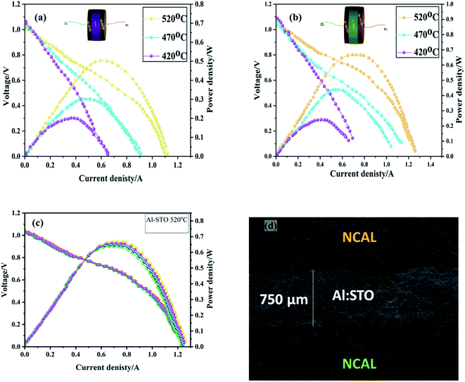
Perovskite oxide doping may modulate the energy bandgap strongly affecting the oxygen reduction activity and electrical properties with high promise for use as a low-temperature solid oxide fuel cell (LT-SOFC) electrolyte. Here, we show that a small amount of Al-doping into SrTiO3−δ may tune the energy band structure of SrTiO3−δ, triggering the electrochemical mechanism and fuel cell performance. The synthesized SrTiO3−δ and Al-SrTiO3−δ electrolytes are sandwiched between two symmetrical electrodes (Ni foam pasted NCAL). Ni-NCAL/SrTiO3−δ/NCAL-Ni and Ni-NCAL/Al-SrTiO3−δ/NCAL-Ni structures delivered a maximum power density of 0.52 W and 0.692 W and high ionic conductivity of 0.11 S cm−1 and 0.153 S cm−1, respectively, under H2/Air atmosphere at low operational temperature of 520 °C. Highways of ion transport along the surface and grain boundary (interface) are identified as the main reason for good oxygen ion conduction. X-ray diffraction (XRD), scanning electron microscopy (SEM), high-resolution transmission electron microscopy (HR-TEM), UV visible (UV), and X-ray photoelectron spectroscopy (XPS) were performed to investigate the structural, electrochemical, morphological, surface and interfacial properties of Al-SrTiO3−δ. The obtained results suggest that a certain amount of Al (20%) doping into SrTiO3 (SrTi0.8Al0.2O3−δ) improves the fuel cell performance and is a promising electrolyte candidate for LT-SOFC.
1. Introduction
Solid oxide fuel cells (SOFCs) convert chemical energy directly into electrical energy. The advantages of SOFCs include fuel flexibility, high-energy conversion efficiency, and environmental friendliness. Key challenges for the commercialization of SOFC include lowering its operating temperature (700–1000 °C) to improve its stability and reducing material costs while maintaining high performance at the same time.1 Furthermore, other material aspects, such as bulk diffusion, are important in affecting the ionic transport in the SOFC electrolyte. Gadolinia-doped ceria (GDC) or Y2O3 stabilized ZrO2 (YSZ) are examples of electrolyte materials used in SOFC, but they mainly are affected by structural doping and the operational temperature of SOFC.2–5 Various advanced thin-film techniques have been employed to manufacture thin-film YSZ-based electrolytes to reduce the operating temperature, but this has also encountered challenges with high cost, long duration of production, and scaling up.6–10 Therefore, the search for alternative electrolyte materials with good ionic properties is of high importance and a challenge without any definitive explanations.6–12To tackle these issues, the interfacial diffusion phenomenon is a promising approach.13–16 Mushtaq et al. reported a composite SrFe0.75Ti0.25O3−δ/Sm0.25Ce0.75O2 (SFT/SDC) heterostructure with high ionic conductivity of >0.1 S cm−1 achieving an impressive fuel cell performance of 920 mW cm−2 at 520 °C. This composite combines a semiconductor (SFT) and ionic conductor (SDC) material to create interfacial mechanisms to obtain such high ionic conductivity.13 A heterostructure composite of semiconductor Ba0.5Sr0.5Co0.1Fe0.7Zr0.1Y0.1O3−δ (BSCFZY) with an ionic conductor Ca0.04Ce0.80Sm0.16O2−δ (SCDC) as a functional electrolyte has demonstrated enhanced ionic conductivity of 0.22 S cm−1 and high-power density of 900 mW cm−2 explained by the influence of interfacial space charge regions and formation of built-in electric field (BIEF) at the interface.14 In addition, an attractive triple-conducting BaCo0.4Fe0.4Zr0.1Y0.1O3−δ electrolyte has been reported, in which an effective p–n junction with BCFZY-ZnO was created to inhibit the electronic conduction and to enhance the charge transport at the interface.15 A power density of 643 mW cm−2 was achieved at 550 °C. Also, many single-phase semiconductors have been suggested as electrolyte membranes for advanced low-temperature solid oxide fuel cells (LT-SOFCs). For example, the semiconductor LixCo0.5Al0.5O2 has been used as an electrolyte, delivering a power density of 180 mW cm−2 at 525 °C and protonic conductivity of 0.1 S cm−1 at 500 °C.16 Such high proton conductivity is affected by the incorporation of H as fuel into the fuel cell.17 A similar example is perovskite SmNiO3 (SNO), which when used as an electrolyte delivered a maximum power density of 225 mW cm−2 with high protonic conductivity at 500 °C.17 The incorporation of protons into the SNO perovskite electrolyte also causes Mott-transition transforming metallic conductor into a proton conductor,17 H-SNO, which is mainly caused due to the coulombic interactions of electrons.17 Such semiconductor electrolytes for the fuel cell can be categorized in the so-called single-layer fuel cell (SLFC) category. Also, perovskite materials such as SrTiO3−δ have attracted extensive attention due to suitable energy bandgap, and physical, chemical, and electrical properties for the application of photocatalysts and fuel cells. Chen et al. have proposed SrTiO3−δ as an electrolyte and delivered better fuel cell performance of 0.62 W cm−2 at 550 °C. Also, several interesting single-layer semiconductors and their hybrid heterostructures have been reported to boost the ionic conductivity of the fuel cell at lower operating temperatures.18–27 The above-stated literature claims that semiconductor electrolytes could be useful in fuel cell applications. Also, SrTiO3 with a bandgap of 3.2 eV has proven to be worthy due to its enriched electrical, physical, and optical properties for various technologies, such as solar cells, batteries, photocatalysis, and fuel cell. According to previous studies, the low valence doping of different elements such as Al3+ into Ti4+ is more effective in boosting the electrical conductivity of SrTiO3.27–29 Moreover, to the best of our knowledge, there is no experimental data have been reported to investigate the effect of Al doping on the energy bandgap and electrical properties for fuel cell application.
To close this knowledge gap, herein, we report a new promising perovskite material Al-SrTiO3−δ (SrTi0.8Al0.2O3−δ). Unlike the SNO, the Al-SrTiO3−δ (SrTi0.8Al0.2O3−δ) is almost an insulator in the as-prepared state but becomes a great ion conductor under the fuel cell conditions, resulting in excellent fuel cell performance of 0.692 W at 520 °C. This greatly enhanced electrical property is attributed to a structural change via doping and a low grain boundary resistance mechanism related to the formation of a heterostructure semiconducting core with a superionic surface layer.
2. Materials and methods
2.1. Synthesis and fabrication of cells
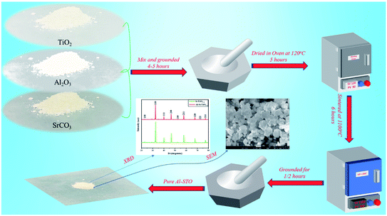
The solid-state method was used to synthesize Al-SrTiO3−δ (SrTi0.8Al0.2O3−δ) electrolyte powders. The perovskite Al-SrTiO3−δ was prepared by grinding precursors of SrCO3, TiO2, and Al2O3 oxides (Sigma Aldrich 99.9% purity). Initially, all oxides materials with appropriate amounts were mixed step by step, consequently grounded, and then ethanol was mixed to obtain a uniform and satisfactory solution. Thereafter, the sample was heated at 120 °C to dry the electrolyte powder and then ground for 5 hours to obtain purely consistent material subsequently sintered at 1100 °C for 6 hours. Besides, STO (SrTiO3−δ) was prepared by the sol–gel technique; the description can be found elsewhere.28 Also, SDC and BZY were prepared through a sol–gel method, details synthesis can be found elsewhere.29 Both pellets were sintered at 1500 °C for 5 hours to obtain the fine structure of SDC and BZY, respectively. The whole synthesis procedure of Al-STO is presented in Fig. 1.2.2. Material characterization
X-ray diffraction (XRD) was performed using an X-ray diffractometer, which contained the Cu (K-alpha) as a source of radiation to elucidate the phase of STO (SrTiO3−δ) and Al-doped STO (Al-SrTiO3−δ). Field emission-scanning electron microscopy (FE-SEM) was performed to investigate the morphologies of the materials. High resolution-transmission electron microscopy (HR-TEM, Tecnai, G2 F30) was performed at an accelerating voltage of 300 kV to investigate the morphology in detail. X-ray photoelectron spectroscopy was deployed to examine the apparent chemical properties of STO (SrTiO3−δ) and Al-doped STO (Al-SrTiO3−δ) materials either in terms of the oxidation state (O–S) or chemical species of surface atoms. UV-visible (UV-3600 spectrometer, MIOSTECHPTY Ltd.) and Ultra-photoelectron spectroscopy studies were performed to manipulate the energy bandgap and valence band maximum position.2.3. Assembly and measurements of the pellet
Later, to fabricate the pellet of the desired electrodes, NCAL powder was purchased from the Tianjin Bamo Sci and Tec Joint-Stock Ltd., China. Also, Ni-foam was cropped and used to collect the current and support the cell. NCAL powder was appropriately mixed with a terpinol binder to obtain a fine and viscous slurry. Subsequently, the prepared slurry was brushed on Ni-foam and then cooked at 80 degrees for 30 min for drying. Furthermore, Ni-foam pasted NCAL electrodes were censored into a pellet of 13 mm in diameter. Then, SrTiO3−δ and Al-SrTiO3−δ electrolyte powders were sandwiched between the Ni-NCAL electrodes and compressed under the 360 MPa to obtain a button-shaped pellet of 13 mm diameter and an active area of 0.64 cm2. The thickness of the prepared pellet was 1.5 mm, while the thickness of the electrolyte was 750 μm. Furthermore, two bilayer electrolyte cells were prepared with STO using SDC and BZY oxide ion and proton conductor in the following configuration of Ni-NCAL/SDC-STO/NCAL-Ni and Ni-NCAL/BZY-STO/NCAL-Ni to distinguish the charge carriers in the SrTiO3−δ electrolyte. The prepared pellets were pressed at 360 MPa, with an active area of 0.64 cm2.Hydrogen fuel (at 80–120 ml min−1 of flow rate) and air (at 150–200 ml min−1) were used to realize the functionality of the fuel cell. The current–voltage (I–V) and current–power (I–P) characteristic curves were plotted using the electronic load (IT8511, ITECH Electrical Co., Ltd) to analyze the fuel cell performance. Moreover, Electrochemical Impedance (EIS) spectra (Gammry-reference 3000, USA) were collected to determine the electrochemical properties under H2/air in the given range of frequency (from 0.1 Hz to 1 MHz) and amplitude of (10 mV).
3. Results and discussion
3.1. Structure and morphology
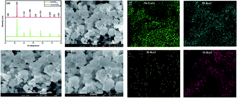
Fig. 2(a) shows the X-ray diffraction pattern of the as-synthesized electrolyte powder SrTiO3−δ and Al-doped SrTiO3−δ (SrTi0.8Al0.2O3−δ), sintered at 1100 °C for 6 hours. The obtained diffraction peaks symbolized the nanocrystalline topographies of the as-synthesized powder. All the diffraction peaks in SrTiO3−δ and Al-SrTiO3−δ had the same patterns, also, all diffraction peaks are indexed to cubic crystalline planes (100), (110), (111), (200), (210), (211), (220), (221), and (310) indicating SrTiO3−δ, Al-SrTiO3−δ belong to a pure cubic crystalline structure. Interestingly, this pattern is according to the previously reported literature.28,29 Also, a pure cubic phase represents that Al is well doped into SrTiO3−δ. The lattice parameters of SrTiO3 and Al-SrTiO3 were calculated using the Rietveld-refinement to be (0.38) nm and (0.3902) nm, respectively. Also, it has been noticed that doping of Al into SrTiO3−δ caused shifting of the peaks toward lower or higher angles, which mainly leads to an increase/decrease in the lattice constant. Also, it happened due to the difference in the ionic radius of the dopant Al (54 pm) and the host Ti (61 pm) elements, which strictly follow Vegards rule.29 Also, it has been speculated that based on the ionic radius, Al3+ is most likely to substitute Ti4+, as confirmed elsewhere.29 Moreover, after testing the scrapped power, the XRD pattern confirmed the formation of amorphous phase LiCO3, as displayed in the supplementary information (Fig. SI1).†Moreover, the morphologies of SrTiO3−δ and Al-doped SrTiO3−δ were investigated using the SEM (scanning electron microscopy) technique. The ImageJ software was used to estimate the particle size from SEM images of the uniformly distributed particles. The particle sizes of SrTiO3−δ and Al-SrTiO3−δ lie in the range of 100–300 nm and 150–300 nm, respectively. SEM results confirmed the coherent distribution and modification due to the incorporation of Al into SrTiO3−δ, as exhibited in Fig. 2(b–d). All particles are homogeneously distributed and well connected in the obtained structure of Al![[thin space (1/6-em)]](https://www.rsc.org/images/entities/char_2009.gif) :
:![[thin space (1/6-em)]](https://www.rsc.org/images/entities/char_2009.gif) STO. Also, the homogeneity and better connection among the particles make them more favorable for better and quick transportation of charges in the electrochemical reaction of a fuel cell.30
STO. Also, the homogeneity and better connection among the particles make them more favorable for better and quick transportation of charges in the electrochemical reaction of a fuel cell.30
Fig. 2(e) shows the EDS of Sr, Al, Ti, and O, which confirms that the particles are spread evenly even after doping, revealing the uniformity, which affirms that Al was doped into SrTiO3−δ (SrTi0.8Al0.2O3−δ).28
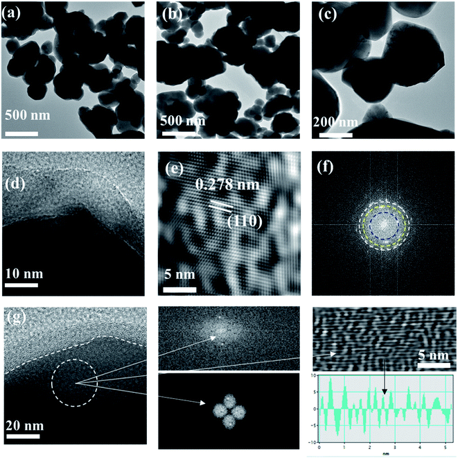
Also, the TEM (transmission electron microscopy) technique was used to study the detailed morphology of SrTiO3−δ and Al-doped SrTiO3−δ, as depicted in Fig. 3(a–c). These TEM images confirmed that the Al-doping into SrTiO3−δ is successful, which probably is beneficial for ionic transport and fuel cell performances to be discussed in a later section. Fig. 3(d and g) shows the HR-TEM of Al-SrTiO3−δ powder scrapped from the cell after testing, leading to a clear view of the core–shell structure. Moreover, Fig. 3(e) is the illustration of the HR-TEM image of the Al-SrTiO3−δ (SrTi0.8Al0.2O3) lattice fringe (110) facet of 0.278 nm, which is less than the STO facet (0.275), confirming the replacement of Ti with Al leading to the expansion of the unit cell volume of the lattice Al-STO, as noticed in XRD.28,29Fig. 3(f) shows the SAEED pattern of the Al-SrTiO3−δ lattice. Also, SEM and TEM images of SrTiO3−δ and Al-SrTiO3−δ are shown in the ESI Fig. SI2(a and b).†
3.2. XPS analysis
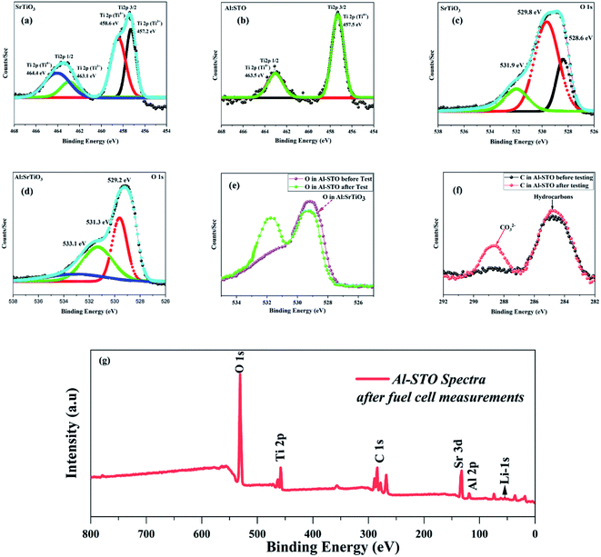
Furthermore, X-ray photoelectron spectra (XPS) were performed on STO and Al-SrTiO3−δ to analyze surface properties and changes in electronic structures brought about by the introduction of the Al lattice, as shown in Fig. SI3.† The XPS spectrum of SrTiO3−δ with the Ti 2p core-level prepared using the sol–gel technique is illustrated in Fig. 4(a), which aligns well with the reported literature spectrum of SrTiO3−δ.31,32 The peaks of the Ti4+ component located at 458.6 and 464.4 eV are allocated to Ti 2p3/2 and Ti 2p1/2, respectively. In contrast, the second doublet located at 457.2 and 463.1 eV gives evidence of the existing Ti3+ species in SrTiO3−δ, as shown in Fig. 4(b).33 From relative peak ratios, mostly titanium is present (72.8%) as Ti4+. In comparison, Ti3+ is available in a lower ratio of about 27.2%, which might appear on the surface in abundance because SrTiO3−δ with a greater concentration of Ti3+ is heavily colored. However, in this study, it appears almost white, and these results are well-matched with the reported data.29In contrast, a single spin-orbital doublet with the features of Ti4+ was noticed in the spectrum of Al-doped SrTiO3−δ, but there was no sign of Ti3+ leading to the fact of Al contribution into the STO lattice prevented the involvement of Ti3+ ions, as hypothesized in the literature.34 In addition, Fig. 4(c and d) shows the O-spectra of SrTiO3−δ and Al-SrTiO3−δ, which suggested that the incorporation of Al3+ ions leads to the modified O1s region of SrTiO3−δ. The peak at 529.8 eV of the SrTiO3−δ lattice is considered the prominent peak assigned to O2− ions in the lattice, while the peak at 531.9 goes to hydroxyl-groups at the surface of particles allotted in previous reports.35–37 Moreover, the peak at 528.6 eV is attributed to the lattice of O2− ions, which are tentatively bonded with Ti3+ ions in the lattice of SrTiO3−δ. This clarification has been confirmed by the disappearance of the peak at 528.6 eV in the Al-SrTiO3−δ lattice, which no longer contains any Ti3+ ions. The peaks at 531.3 eV and 529.2 eV are allotted to the surface hydroxyl groups and lattice oxide O2− ions, suggesting an increase in the surface hydroxyl groups in Al-SrTiO3−δ. The peak at 531.8 eV in the Al-SrTiO3−δ lattice is tentatively attributed to the oxide ions bonded to Al3+ ions near the surface.38 The peak at 533.1 eV belonged to SrCO3, which might be produced as a side product during the synthesis process.39
Generally, a 0.5–0.6 shift in all peaks toward lower binding energy has been revealed after a detailed inspection of Ti and O core-level spectra, and this change in B.E. might be attributed to the alternation in the charge distribution leading to enhancement of the oxygen vacancies, as a result, enhancing of the ionic conductivity.40,41 Moreover, the peak area was expanded upon doping, resembling the creation of more O-vacancies and high ionic conduction channels. Fig. 4(e and f) reveals the XPS spectra of C1s and O1s of the prepared sample Al-SrTiO3−δ powder before and after the performance. The peak at 284.2 eV of C1s was assigned to C–H, while the peak at 288.9 eV was attributed to CO32−. XPS spectra of C1s give the clue of carbonate existence on the surface of Al-SrTiO3−δ after the fuel cell performance. Moreover, Fig. 4(g) shows the XPS spectra of Al-SrTiO3−δ with the indication of the Li-1s peak, confirming the formation of Li2Co3 after fuel cell measurements. From the O1s spectra, the existence of the lattice oxygen hydroxyl groups and oxygen defects were noticed, as shown in Fig. 4(c and d). While the spectra after the performance revealed the presence of oxygen with a high oxidation state in abundant O-vacancies, OH groups, and carbonates appeared on the surface of Al-SrTiO3−δ leading to enhancing the ionic conductivity.42
3.3. Fuel cell performance
To evaluate the fuel cell performance of SrTiO3−δ and Al-SrTiO3−δ electrolytes, the symmetrical electrodes (anode and cathode) NCAL were shaped into pellets in the following configuration of Ni-NCAL/SrTiO3−δ and Al-SrTiO3−δ/NCAL-Ni, as illustrated in Fig. 5(a and b). The electrochemical performance was evaluated in different gas H2/air environments at low operating temperatures of 420–520 °C. The constructed device (Ni-NCAL/Al-SrTiO3−δ/NCAL-Ni) conveyed the outstanding OCV 1.05, 1.03, and 1.04 V at 420, 470, and 520 °C, respectively. Also, a peak power density (PPD) of 0.692 W was obtained utilizing the Al-SrTiO3−δ electrolyte, superior to the pure SrTiO3−δ (0.52 W) electrolyte at a low-temperature 520 °C. It can be perceived that such high performance is typically attained in traditional SOFCs using thin-film electrolytes.43 The cell showed excellent performance, and some credit for the high performance goes to the composite Ni-NCAL electrodes.44 Also, the obtained power density is much higher than that reported for titanate-based materials, such as STO, Fe-SrTiO3, and Nb-SrTiO3, revealing the reliability of Al-SrTiO3−δ as a competent electrolyte for LT-SOFCs.17,28,30The question is, how and why should Al-SrTiO3−δ be used as an electrolyte with such high performance? Well, it has been reported that the Al-SrTiO3−δ is an electronic conductor in a reducing atmosphere,28 and the OCV agrees with the theoretical Nernst potential.29,30 However, when H2 and air are injected into both sides of the pellets, the OCV starts to increase, reaching 1.1 V. Such a high OCV indicates that neither the gas leakage nor the short-circuiting occurred in our device, guaranteeing a peak power density (PPD) of 0.692 W. The OCV has shown the operating temperatures upgrading behavior; similarly, as temperature decreases, OCV increases, which follows the Nernst equation.28,30 The higher power density and the OCV with the temperature variation avoid the short-circuiting issue due to the formation of the interface junction of the core–shell heterostructure, doping, and the Schottky junction.25,28,29 It has been speculated that the formation of the Schottky junction among the anode and electrolyte interface inhibits electronic conduction and enhances ionic transportation.28Fig. 5(c) exhibits the I–V/I–P characteristic curves of Ni-NCAL/Al-SrTiO3−δ/NCAL-Ni in an H2/air environment delivering almost the same power density ∼0.692 W each time of repeating 4 to 5 times at 520 °C. Fig. 5(d) displays the cross-sectional view of the NCAL/Al-SrTiO3−δ/NCAL cell surveyed via SEM (scanning electron microscopy), where Al-SrTiO3−δ is well sandwiched and distinguished among the porous symmetrical electrodes (NCAL), which guarantees better performance.45
NCAL has been recognized as an excellent electrode candidate either as a cathode or anode in search of better material with excellent ionic and electronic conductivity. Comparatively, NCAL has better catalytic activity and excellent redox (HOR and ORR) reactions in the anode and cathode zones, respectively.45 The credit for the higher OCV goes to the good catalytic activity of electrodes NCAL (anode and cathode). Higher power and enhanced OCV evidenced the feasibility of Al-SrTiO3−δ as a capable potential electrolyte in LT-SOFCs. All results imply that Al-SrTiO3−δ is a better electrolyte, but still much more effort is needed, especially engineering ones (thin-film techniques), and the heterostructure of Al-SrTiO3−δ prepared using the thin-film technique is in desperate demand to support the most advanced technology.
3.4. EIS analysis and ionic conductivity
Moreover, electrochemical analysis (EIS) was performed to further study the electrical properties of SrTiO3−δ and Al-SrTiO3−δ under the OCV conditions with an H2/air environment at different operating temperatures (420–520 °C), as depicted in Fig. 6(a and b). On the real axis, first, the intercept with a higher frequency corresponds to the ohmic resistance. It gives different values (0.32, 0.44, 0.64) for STO and (0.18, 0.20, 0.29) for Al-SrTiO3−δ under different operating temperatures 520–420 °C. NCAL has been recognized as a better electronic conductor, and when it combines or is pasted on Ni foam, it even delivers superior conductivity.45 It means that our investigated cells' ohmic resistance should come from the SrTiO3−δ/Al-SrTiO3−δ electrolytes. Polarization resistance is defined as the difference between the high frequency and low-frequency intercept on the EIS curve's real axis, composed of several overlapping suppressed arcs. These suppressed arcs represent the physical and chemical processes corresponding to the HOR (hydrogen–oxidation reaction) and ORR (oxygen–reduction reaction) at the anode and cathode sides. All the suppressed semi-circles were fitted by applying the following circuit (LRo(QR1)(QR2)) in the ZSIMPWIN software, where R1 manifests the charge transfer resistance (grain-boundary resistance), R2 corresponds to the mass transfer resistance, and Ro represents the ohmic resistance. The detailed values of the fitted circuit are shown in the supplementary information (Table SI 1 and 2).† The decline in the charge transfer resistance of the cell might be followed by the capacitance (Ci), which can be determined using the equation Ci = RiQi1/n/Ri.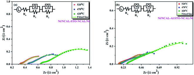 | ||
| Fig. 6 (a and b) Electrochemical impedance spectroscopy curves of SrTiO3−δ and Al-SrTiO3−δ in H2/air environment at different operating temperatures 420–520 °C. | ||
R i corresponds to Qi, and n, represents the frequency power related to the Q value [0 < n < 1].43–45 The obtained capacitance and resistance values showed declining behavior, suggesting the enhanced charge transfer at the interface and the surface, leading to peak power density (PPD) and high ionic conductivity. The above results imply that doping causes to create more O-vacancies leading to higher ionic conductivity. Also, the presence of LiCO3 was evidenced from the anode side of NCAL as Ni-NCAL was reduced to Ni, and Li-Co-Al and formed LiCO3 by H2 at the anode side. It might be possible to infer that the formed LiCO3 plays an essential role in easing the conduction of oxygen ions (O2−). Overall, oxygen vacancies induced by doping and surface conduction of the core–shell interface play a critical role in boosting the ionic conductivity.28 The mechanism of the core–shell heterojunction will be discussed in the later section.
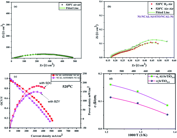
The ionic conductivity of Al-SrTiO3−δ is high enough for the reported heterostructure electrolyte materials in the fuel cell devices, especially at low operating temperatures. Therefore, to investigate the ionic conduction and charge transfer mechanism of Al-SrTiO3−δ electrolyte, different gas atmospheres were provided to analyze the cell through changes in the impedance spectrum. At first, the air–air atmosphere was inserted before the fuel cell performance to examine the ionic conductivity at 520 °C. As a result, a giant arc appears, composed of many suppressed arcs with a total impedance approaching 500 Ω cm2, as depicted in Fig. 7(a). Such high resistance under the air–air atmosphere suggests low ionic conductivity in the current state. In a while, one side of the air was replaced with H2 and left for 10 minutes to flow appropriately. Afterward, it yielded lower ohmic resistance and polarization resistance at 520 °C under H2/air environment, which is generously lower than the air/air atmosphere, as shown in Fig. 7(b). Later, H2 in the cell was purged using N2 and air for almost 1 hour, and then the air/air environment was repeated with EIS, which yielded virtually the same ohmic resistance as in H2/air environment; also, the total resistance did not repeat to the 500 ohm cm2 leading to the fact that oxygen ions might be the charge carriers in Al-SrTiO3−δ.22,28 Such a high carrier concentration owes to the doping of Al into SrTiO3−δ and the formation of the core–shell structure in a single-phase material for the fuel cell device, also, such results manifest that Al-SrTiO3−δ holds a significant capability to work as a potential electrolyte with better ionic conductivity for SOFCs.28
In addition, two double-layer electrolytes were prepared to identify the charge carriers in Al-SrTiO3−δ using the ion filtration experiment. SDC and BZY were synthesized using co-precipitation and sol–gel techniques as oxide ion and proton conductors, respectively. The prepared cells of the following configuration Ni-NCAL-SDC/Al-SrTiO3−δ-NCAL/Ni & Ni-NCAL-BZY/Al-SrTiO3−δ-NCAL/Ni were used to construct the I–V/I–P curves, as demonstrated Fig. 7(c). Ni-NCAL-SDC/Al-STO-NCAL/Ni and Ni-NCAL-BZY/Al-STO-NCAL/Ni delivered the maximum power output of 180 mW cm−2 and 149 mW cm−2 with better OCVs of 0.97 and 1 V, respectively. The ionic conductivities of SDC and BZY were lower than that of Al-SrTiO3−δ, as reported elsewhere.27 The obtained power output of both double-layer electrolytes proved that Al-SrTiO3−δ contains proton and oxide ion carriers.
Moreover, the ionic conductivity was elucidated using the I–V curve. The central region of the I–V curve gives the clue of ionic resistance of ohmic resistance, which was extracted to investigate the ionic conductivity of 0.153 S cm−1 at 520 °C as shown in Fig. 7(d).45 The obtained ionic conductivity of 0.153 S cm−1 is higher than STO, suggesting that doping and surface conduction are causing to enhance the ionic conduction. Moreover, the attained ionic conductivity is higher than the reported values for titanate-based materials (SrTiO3, Fe-SrTiO3), which have increased the worth of Al-STO as a capable electrolyte for the fuel cell application.17,28,30 The high ionic conductivity of 0.153 S cm−1 and the low activation energy of 0.31 eV indicate the capability of Al-SrTiO3−δ as an electrolyte for SOFC devices at low operational temperatures. Such high ionic conduction is mainly a result of the formation of the core–shell heterojunction.26,27
3.5. Optical features and junction mechanism
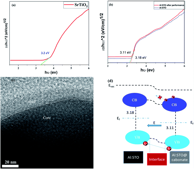
To investigate the charge transport behavior in energy devices, exclusively in fuel cell devices, the energy band theory should be adopted to design the energy bands of materials from a different perspective. The energy bandgaps of SrTiO3−δ, Al-SrTiO3−δ, and Al-SrTiO3−δ@carbonates after the performance were investigated using the UV-analysis, as depicted in Fig. 8(a and b). The absorption edge spectra for the SrTiO3−δ electrolyte material were noticed at 240 nm. At the same time, Al-SrTiO3−δ and Al-SrTiO3−δ@carbonates or after the performance seem to move toward a higher wavelength (red-shift), as hypothesized in previous reports.28 According to the relationship between h (eV) and (αhυ)2, Tauc plots were plotted and are displayed in Fig. 8(a and b). The following relation was used to infer the energy bandgap.29| (αhυ)2 = B(hυ − Eg) |
The details of the above equation parameters are explained elsewhere.29 The obtained energy bandgaps 3.2, 3.18, and 3.11 eV correspond to SrTiO3−δ, Al-SrTiO3−δ, and Al-SrTiO3−δ@carbonates or after the performance. The calculated energy bandgap is well matched to that published previously.28,29 After incorporating Al in SrTiO3−δ, the bandgap was reduced. Afterward, we noticed that after the performance, the bandgap of Al-SrTiO3−δ tended to decrease, which might have occurred due to the creation of intermediate states between the valence and conduction band. Moreover, reduced energy bandgap is mainly ascribed to creating O-vacancies in the lattice and at the surface and interface. This O-vacancies creation phenomenon leads to the establishment of the above-mentioned energy levels, which primarily affect the Fermi-level and energy bandgap.43 Moreover, ultra-photoelectron spectroscopy (UPS) was used to determine the valence band values, which were 7.37 and 8.3 eV for Al-SrTiO3−δ and Al-SrTiO3−δ@carbonates, respectively, as displayed in (Fig. SI 4).†
Fig. 8(c and d) shows the HR-TEM images identifying the core–shell heterojunction between the two phases and the energy band diagram constructed based on the inferred bandgap for Al-SrTiO3−δ and Al-SrTiO3−δ@carbonates. The band alignment between Al-SrTiO3−δ or phase 1 and Al-SrTiO3−δ@carbonates or phase 2 was established due to the reduction in the bandgap after the performance in phase 2. The amorphous carbonate phase might accumulate on the surface of bulk Al-SrTiO3−δ or phase 1 and permeate into the superficial phase 1 to establish the core–shell heterostructure, as shown in Fig. 8(c). The core–shell heterojunction between phases 1 and phase 2 can be formed, leading to separating the electron–hole pairs and producing BIEF (build-in electric field), as shown in Fig. 8(d). Reasonably, the junction between phase 1 and 2 leads to enhanced ionic conductivity, and BIEF blocks the electronic movement and facilitates fast charge transportation, as in the P–N junction.14,15 It can be inferred that the core–shell heterojunction is the driving force to enhance the ionic conductivity and performance, and Al-SrTiO3−δ holds the capability to be a capable electrolyte for advanced fuel cell technology.
3.6. Durability of LT-SOFC
Fig. 9(a and b) shows SrTiO3−δ and Al-SrTiO3−δ structures in the b–c plane, signifying that Al is well fitted into SrTiO3−δ. Moreover, Fig. 9(c) exhibits the schematic diagram of a fuel cell composed of electrolyte Al-SrTiO3−δ and symmetrical electrodes Ni-NCAL. Furthermore, as we know, the durability of low-temperature SOFCs is crucially tricky in practical applications. However, the stability of the semiconductor fuel cells is crucial to promoting fuel cell technology. Therefore, to assess the stability of the semiconductor materials, Ni-NCAL/Al-SrTiO3−δ/NCAL-Ni electrolyte voltage with constant current density was recorded as a function of time, and SOFC devices were set to operate at a low temperature of 520 °C in different gas H2/air environments. The accomplished results of our intended fuel cell device stay stable for more than 28 h under 100 mA cm2− at 520 °C. Our proposed device has delivered an appropriate power density and stable voltage (0.84 V) at a low temperature of 520 °C, as shown in Fig. 9(d). Still, we failed to obtain long-term stability, as such long-term stability (>100 h) needs better technical engineering and technology in terms of compatible electrodes, which can be pursued in the future.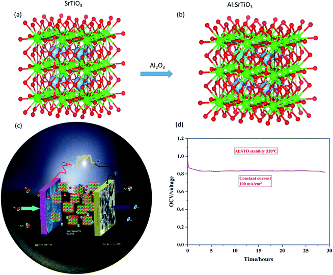 | ||
| Fig. 9 (a and b) Structures of pure SrTiO3−δ and Al-SrTiO3−δ, while (c and d) are schematic diagrams of Al-SrTiO3−δ fuel cell and durability of Al-SrTiO3−δ at a low operating temperature 520 °C. | ||
4. Conclusion
A novel semiconductor membrane Al-SrTiO3−δ was prepared as an electrolyte in layered (Ni-NCAL)/Al-SrTiO3−δ (STO)/NCAL-Ni fuel cell at low-temperature operation (420–520 °C). Al-SrTiO3−δ powder was synthesized by the solid-state method and a symmetrical fuel cell was prepared by the co-pressing method using Al-SrTiO3−δ as an electrolyte layer. The prepared device achieved a maximum power density of 0.692 W having high ionic conductivity of 0.153 S cm−1 at 520 °C in H2/air. It was found that after introducing H2 into the cell, the Al-SrTiO3−δ electrolyte experienced a significant transition in the ionic conductivity, transforming from an insulator to a high ionic conductor. The experimental results of SDC/Al-SrTiO3−δ and BZY/Al-SrTiO3−δ double-layer electrolyte cells showed that the Al-SrTiO3−δ electrolyte is a mixed conductor of protons and oxygen ions. XRD, XPS, HRTEM, and UV-visible studies showed that a lithium carbonate layer was formed on the Al-STO surface after the performance testing, which constitutes a composite electrolyte with a core–shell structure. The composite electrolyte Al-SrTiO3−δ–Li2CO3 has a high conductivity for oxygen, proton, and carbonate ions. The carbonate originates in NCAL from the atmospheric CO2 and is transferred from the NCAL electrode to the electrolyte. The formation of the core–shell heterojunction inhibits the electronic conduction and seems to level up the charge carrier transport through the band alignment mechanism (BIEF) at the surface and interface. Profound studies on the core–shell junction would be useful for future studies on the subject.Conflicts of interest
We do not have any competing financial interests or personal relationships that may influence the work reported here.Acknowledgements
This work was supported by Southeast University (SEU) PROJET # 3203002003A1 and the National Natural Science Foundation of China (NSFC) under grants # 51772080 and 11604088. Jiangsu Provincial Innovation and Entrepreneurship Talent Program Project No. JSSCRC2021491. Industry-University-Research Cooperation Project of Jiangsu Province in China, Grant No. BY2021057. Dr Asghar thanks the Hubei Talent 100 Program and the Academy of Finland (Grant No. 13329016, 13322738) for their financial support.References
- J. B. Goodenough, Oxide-Ion Conductors by Design, Nature, 1999, 404, 821–823 CrossRef PubMed.
- O. Yamamoto, Y. Arati, Y. Takeda, N. Imanishi, Y. Mizutani, M. Kawai and Y. Nakamura, Electrical Conductivity of Stabilized Zirconia with Ytterbia and Scandia, Solid State Ionics, 1995, 79, 137–142 CrossRef CAS.
- C. Varanasi, C. Juneja, C. Chen and B. Kumar, Electrical Conductivity Enhancement in Heterogeneously Doped Scandia-Stabilized Zirconia, J. Power Sources, 2005, 147, 128–135 CrossRef CAS.
- M. Mogensen, N. M. Sammes and G. A. Tompsett, Physical, Chemical and Electrochemical Properties of Pure and Doped Ceria, Solid State Ionics, 2000, 129, 63–94 CrossRef CAS.
- D. Lee, J. H. Han, Y. Chun, R. H. Song and D. R. Shin, Preparation and Characterization of Strontium and Magnesium Doped Lanthanum Gallates as the electrolyte for IT-SOFC, J. Power Sources, 2007, 166, 35–40 CrossRef CAS.
- Z. Shao and S. M. Haile, A High-Performance Cathode for the Next Generation of Solid-Oxide Fuel Cells, Nature, 2004, 431, 170–173 CrossRef CAS PubMed.
- S. Tao and J. T. S. Irvine, A Redox-Stable Efficient Anode for Solid-Oxide Fuel Cells, Nat. Mater., 2003, 2, 320–323 CrossRef CAS PubMed.
- T. Suzuki, Z. Hasan, Y. Funahashi, T. Yamaguchi, Y. Fujishiro and M. Awano, Impact of Anode Microstructure on Solid Oxide Fuel Cells, Science, 2009, 325, 852–855 CrossRef CAS PubMed.
- A. Evans, J. Martynczuk, D. Stender, C. W. Schneider, T. Lippert and M. Prestat, Low-Temperature Micro-Solid Oxide Fuel Cells with Partially Amorphous La0.6Sr0.4CoO3−δ Cathodes, Adv. Energy Mater., 2000, 288, 2031–2033 CrossRef PubMed.
- B. Iwanschitz, J. Sfeir, A. Mai and M. Schütze, Degradation of SOFC Anodes upon Redox Cycling: a Comparison Between Ni/YSZ and Ni/CGO, J. Electrochem. Soc., 2010, 157, B269–B278 CrossRef CAS.
- D. Waldbillig, A. Wood and D. G. Ivey, Electrochemical and Microstructural Characterization of the Redox Tolerance of Solid Oxide Fuel Cell Anodes, J. Power sources, 2005, 145, 206–215 CrossRef CAS.
- B. Timurkutluk, C. Timurkutluk, M. D. Mat and Y. Kaplan, A review on cell/stack designs for high performance solid oxide fuel cells, Renewable Sustainable Energy Rev., 2016, 56, 1101–1121 CrossRef CAS.
- N. Mushtaq, C. Xia, W. Dong, B. Wang, R. Raza, A. Ali, M. Afzal and B. Zhu, Tuning the energy band structure at interfaces of the SrFe0.75Ti0.25O3−δ–Sm0.25Ce0.75O2−δ heterostructure for fast ionic transport, ACS Appl. Mater. Interfaces, 2019 Oct 8, 11(42), 38737–38745 Search PubMed.
- S. Rauf, B. Zhu, M. A. Yousaf Shah, Z. Tayyab, S. Attique, N. Ali, N. Mushtaq, B. Wang, C. Yang, M. I. Asghar and P. D. Lund, Application of a triple-conducting heterostructure electrolyte of Ba0.5Sr0.5Co0.1Fe0.7Zr0.1Y0.1O3−δ and Ca0.04Ce0.80Sm0.16O2−δ in a high-performance low-temperature solid oxide fuel cell, ACS Appl. Mater. Interfaces, 2020, 12(31), 35071–35080 CrossRef CAS PubMed.
- C. Xia, Y. Mi, B. Wang, B. Lin, G. Chen and B. Zhu, Shaping triple-conducting semiconductor BaCo0.4Fe0.4Zr0.1Y0.1O3−δ into an electrolyte for low-temperature solid oxide fuel cells, Nat. Commun., 2019, 10(1), 1–9 CrossRef CAS PubMed.
- R. Lan and S. Tao, Novel Proton Conductors in the Layered Oxide Material LixlAl0.5Co0.5O2, Adv. Energy Mater., 2014, 4, 1301683 CrossRef.
- Y. Zhou, X. Guan, H. Zhou, K. Ramadoss, S. Adam, H. Liu, S. Lee, J. Shi, M. Tsuchiya, D. D. Fong and S. Ramanathan, Strongly correlated perovskite fuel cells, Nature, 2016, 534, 231–234 CrossRef CAS PubMed.
- M. Y. Shah, S. Rauf, N. Mushtaq, Z. Tayyab, N. Ali, M. Yousaf, Y. Xing, M. Akbar, P. D. Lund, C. P. Yang and B. Zhu, Semiconductor Fe-doped SrTiO3−δ perovskite electrolyte for low-temperature solid oxide fuel cell (LT-SOFC) operating below 520 °C, Int. J. Hydrogen Energy, 2020, 45(28), 14470–14479 CrossRef CAS.
- M. A. Shah, N. Mushtaq, S. Rauf, C. Xia and B. Zhu, The semiconductor SrFe0.2Ti0.8O3−δ–ZnO heterostructure electrolyte fuel cells, Int. J. Hydrogen Energy, 2019, 44(57), 30319–30327 CrossRef.
- M. Y. Shah, N. Mushtaq, S. Rauf, N. Akbar, Y. Xing, Y. Wu, B. Wang and B. Zhu, Advanced fuel cell based on semiconductor perovskite La–BaZrYO3−δ as an electrolyte material operating at low temperature 550 °C, Int. J. Hydrogen Energy, 2020, 45(51), 27501–27509 CrossRef CAS.
- M. Y. Shah, Z. Tayyab, S. Rauf, M. Yousaf, N. Mushtaq, M. A. Imran, P. D. Lund, M. I. Asghar and B. Zhu, Interface engineering of bi-layer semiconductor SrCoSnO3−δ–CeO2−δ heterojunction electrolyte for boosting the electrochemical performance of low-temperature ceramic fuel cell, Int. J. Hydrogen Energy, 2021, 46(68), 33969–33977 CrossRef CAS.
- M. Y. Shah, S. Rauf, N. Mushtaq, B. Zhu, Z. Tayyab, M. Yousaf, M. B. Hanif, P. D. Lund, Y. Lu and M. I. Asghar, Novel Perovskite Semiconductor Based on Co/Fe-Codoped LBZY (La0.5Ba0.5Co0.2Fe0.2Zr0.3Y0.3O3−δ) as an Electrolyte in Ceramic Fuel Cells, ACS Appl. Energy Mater., 2021, 4(6), 5798–5808 CrossRef CAS.
- B. Zhu, R. Raza, G. Abbas and M. Sing, An Electrolyte-Free Fuel Cell Constructed from One Homogenous Layer with Mixed Conductivity, Adv. Funct. Mater., 2011, 21, 2465–2469 CrossRef CAS.
- B. Zhu, R. Raza, H. Qin, Q. Liu and L. Fan, Fuel cells based on electrolyte and non-electrolyte separators, Energy Environ. Sci., 2011, 4, 2986–2992 RSC.
- L. Fan, C. Wang, M. Chen and B. Zhu, Recent development of ceria-based (nano)composite materials for low temperature ceramic fuel cells and electrolyte-free fuel cells, J. Power Sources, 2013, 234, 154–174 CrossRef CAS.
- G. Zhang, W. Li, W. Huang, Z. Cao, K. Shao, F. Li, C. Tang, C. Li, C. He, Q. Zhang and L. Fan, Strongly coupled Sm0.2Ce0.8O2–Na2CO3 nanocomposite for low temperature solid oxide fuel cells: one-step synthesis and super interfacial proton conduction, J. Power Sources, 2018, 386, 56–65 CrossRef CAS.
- G. Chen, H. Liu, Y. He, L. Zhang, M. I. Asghar, S. Geng and P. D. Lund, Electrochemical mechanisms of an advanced low-temperature fuel cell with a SrTiO3 electrolyte, J. Mater. Chem. A, 2019, 7(16), 9638–9645 RSC.
- G. Chen, W. Sun, Y. Luo, Y. He, X. Zhang, B. Zhu, W. Li, X. Liu, Y. Ding, Y. Li and S. Geng, Advanced fuel cell based on new nanocrystalline structure Gd0.1Ce0.9O2 electrolyte, ACS Appl. Mater. Interfaces, 2019, 11(11), 10642–10650 CrossRef CAS PubMed.
- Z. Zhao, R. V. Goncalves, S. K. Barman, E. J. Willard, E. Byle, R. Perry, Z. Wu, M. N. Huda, A. J. Moulé and F. E. Osterloh, Electronic structure basis for enhanced overall water splitting photocatalysis with aluminum-doped SrTiO3 in natural sunlight, Energy Environ. Sci., 2019, 12(4), 1385–1395 RSC.
- M. Y. Shah, S. Rauf, B. Zhu, N. Mushtaq, M. Yousaf, P. D. Lund, C. Xia and M. I. Asghar, Semiconductor Nb-Doped SrTiO3−δ Perovskite Electrolyte for a Ceramic Fuel Cell, ACS Appl. Energy Mater., 2021, 4(1), 365–375 CrossRef CAS.
- N. Mushtaq, Y. Lu, C. Xia, W. Dong, B. Wang, M. Y. Shah, S. Rauf, M. Akbar, E. Hu, R. Raza and M. I. Asghar, Promoted electrocatalytic activity and ionic transport simultaneously in dual functional Ba0.5Sr0.5Fe0.8Sb0.2O3-δ-Sm0.2Ce0.8O2-δ heterostructure, Appl. Catal., B, 2021 Dec 5, 298, 120503 Search PubMed.
- R. P. Vasquez, SrTiO3 by XPS, Surf. Sci. Spectra, 1992 Mar, 1(1), 129–135 Search PubMed.
- H. Tan, Z. Zhao, W. B. Zhu, E. N. Coker, B. Li, M. Zheng, W. Yu, H. Fan and Z. Sun, Oxygen vacancy enhanced photocatalytic activity of perovskite SrTiO3, ACS Appl. Mater. Interfaces, 2014, 6(21), 19184–19190 CrossRef CAS PubMed.
- Y. Fu, H. Du, S. Zhang and W. Huang, XPS characterization of surface and interfacial structure of sputtered TiNi films on Si substrate, J. Mater. Sci. Eng. A, 2005, 403(1–2), 25–31 CrossRef.
- P. V. Nagarkar, P. C. Searson and F. D. Gealy III, Effect of surface treatment on SrTiO3: an X-ray photoelectron spectroscopic study, J. Appl. Phys., 1991, 69(1), 459–462 CrossRef CAS.
- J. Chastain and R. C. King Jr. Handbook of X-ray photoelectron spectroscopy, Perkin-Elmer, USA, 1992, p. 261 Search PubMed.
- Y. Zhu, P. A. Salvador and G. S. Rohrer, Controlling the relative areas of photocathodic and photoanodic terraces on the SrTiO3 (111) surface, Chem. Mater., 2016, 28(14), 5155–5162 CrossRef CAS.
- E. W. McCafferty and J. P. Wightman, Determination of the concentration of surface hydroxyl groups on metal oxide films by a quantitative XPS method, Surf. Interface Anal., 1998, 26(8), 549–564 CrossRef CAS.
- M. El Kazzi, G. Delhaye, C. Merckling, E. Bergignat, Y. Robach, G. Grenet and G. Hollinger, Epitaxial growth of SrO on Si (001): chemical and thermal stability, J. Vac. Sci. Technol., A, 2007, 25(6), 1505–1511 CrossRef CAS.
- T. Sun and M. Lu, Band-structure modulation of SrTiO3 by hydrogenation for enhanced photoactivity, Appl.Phys.A: Mater.Sci.Process., 2012, 108(1), 171–175 CrossRef CAS.
- M. Copel, P. R. Duncombe, D. A. Neumayer, T. M. Shaw and R. M. Tromp, Metallization induced band bending of SrTiO3 (100) and Ba0.7Sr0.3TiO3, Appl. Phys. Lett., 1997, 70(24), 3227–3229 CrossRef CAS.
- R. P. Vasquez, SrTiO3 by XPS, Surf. Sci. Spectra, 1992, 1(1), 129–135 CrossRef CAS.
- S. Rauf, B. Zhu, M. Y. Shah, C. Xia, Z. Tayyab, N. Ali, C. Yang, N. Mushtaq, M. I. Asghar, F. Akram and P. D. Lund, Tailoring triple charge conduction in BaCo0.2Fe0.1Ce0.2Tm0.1Zr0.3Y0.1O3−δ semiconductor electrolyte for boosting solid oxide fuel cell performance, Renewable Energy, 2021, 172, 336–349 CrossRef CAS.
- D. Yang, G. Chen, H. Liu, L. Zhang, Y. He, X. Zhang, K. Yu, S. Geng and Y. Li, Electrochemical performance of a Ni0.8Co0.15Al0.05LiO2 cathode for a low temperature solid oxide fuel cell, Int. J. Hydrogen Energy, 2021, 46(17), 10438–10447 CrossRef CAS.
- N. Mushtaq, Y. Lu, C. Xia, W. Dong, B. Wang, X. Wang, M. Y. Shah, S. Rauf, N. Jingjing, E. Hu and H. Xiao, Design principle and assessing the correlations in Sb-doped Ba0.5Sr0.5FeO3–δ perovskite oxide for enhanced oxygen reduction catalytic performance, J. Catal., 2021, 395, 168–177 CrossRef CAS.
Footnote |
† Electronic supplementary information (ESI) available: Fig. 1 exhibits the XRD patterns of Al-STO before and after testing, Fig. 2(a and b) show scanning electron microscopy images of STO and Al-STO at a 1 μm magnification scale, while (c) shows the HR-TEM image of Al![[thin space (1/6-em)]](https://www.rsc.org/images/entities/char_2009.gif) : :![[thin space (1/6-em)]](https://www.rsc.org/images/entities/char_2009.gif) STO before testing, Fig. 3 shows the X-ray photoelectron spectroscopy (XPS) spectra of STO and Al-STO and Fig. 4(a and b) shows UV-visible absorption spectra of Al-STO before and after testing, while, (c and d) reveals the UPS spectra of Al STO before testing, Fig. 3 shows the X-ray photoelectron spectroscopy (XPS) spectra of STO and Al-STO and Fig. 4(a and b) shows UV-visible absorption spectra of Al-STO before and after testing, while, (c and d) reveals the UPS spectra of Al![[thin space (1/6-em)]](https://www.rsc.org/images/entities/char_2009.gif) : :![[thin space (1/6-em)]](https://www.rsc.org/images/entities/char_2009.gif) STO before and after testing, Tables 1 and 2 show the fitted parameters of EIS data. See https://doi.org/10.1039/d2se00643j STO before and after testing, Tables 1 and 2 show the fitted parameters of EIS data. See https://doi.org/10.1039/d2se00643j |
| This journal is © The Royal Society of Chemistry 2022 |

