 Open Access Article
Phase transformations in the nickel phosphide system induced by transition-metal doping and their electro-catalytic study†
Gwaza E.
Ayom
 a,
Malik D.
Khan
 ab,
Siphamandla C.
Masikane
 a,
Felipe M.
de Souza
c,
Wang
Lin
c,
Ram K.
Gupta
c and
Neerish
Revaprasadu
 *a
*a
aDepartment of Chemistry, University of Zululand, Private Bag X1001, KwaDlangezwa 3880, South Africa. E-mail: RevaprasaduN@unizulu.ac.za
bInstitute of Physical Chemistry, Polish Academy of Sciences, Kasprzaka 44/52, 01-224, Warsaw, Poland
cDepartment of Chemistry, Kansas Polymer Research Center, Pittsburg State University, Pittsburg, KS 66762, USA
First published on 24th January 2022
Abstract
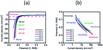
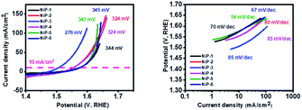
Nickel phosphide exists in various compositions, and the synthesis of pure-phase nickel phosphides is of immense interest due to their wide scale applications in different electrocatalytic reactions. We report the facile synthesis of nickel phosphides and rare transition metal-induced phase transformations within this system. Phase selective synthesis of pure Ni2P or Ni5P4 was achieved by decomposition of nickel acetate tetrahydrate Ni(AC)2·4H2O in optimized mixed solvent systems, i.e., in tri-octylphosphine oxide (TOPO)/tri-n-octylphosphine (TOP) or hexadecylamine (HDA)/TOP, respectively, by hot injection route. The doping of 5% Cu or Mn in either of the nickel phosphide phases yielded a mixture of phases (Ni2P/Ni5P4). However, increasing the Cu or Mn content to 10% resulted in the complete transformation of phase, i.e., from Ni2P to pure Ni5P4 and vice versa. Lattice stress and size of incorporated dopants, as well as the nature of surfactants employed, were discussed as probable causes of these rare phase transformations. Moreover, in order to establish structure–activity relationship, we studied the comparative effect of transition metal dopants in both nickel rich and nickel deficient phases. Therefore, initially formed and transformed phosphides were investigated as electrocatalysts for overall water splitting and supercapacitance. NiP-5 (Ni2P formed on 10% Cu doping of Ni5P4) delivered a current density of 10 mA cm−2 with the lowest overpotential of 146 mV among all samples for HER while NiP-3 (Ni5P4 formed from Ni2P on 10% Cu doping) similarly required the least overpotential of 276 mV for the OER at the same current density. NiP-2 (pristine Ni5P4) had the highest calculated specific capacitance of 1325 F g−1 at 2 A g−1. These phase transformations resulted in better catalytic activity and stability as well as reaction kinetics indicating suitability in practical water splitting technologies.
Introduction
Transition metal phosphides, in particular nickel phosphides, are of interest to materials scientists due to their applications in energy storage,1–3 energy generation,4 bio-sensing5 and catalytic recycling.6 Reports on nickel phosphides are limited compared to the sulfide analogs because their preparation is constrained by factors such as toxicity, prolonged reaction times, elevated temperatures and multiple starting precursors.3The reactions that evolve hydrogen and oxygen (water splitting) at the electrodes continue to attract attention from the scientific community. This is due to the potential of these reactions changing our planet's over-reliance on fossil fuels for its energy requirements.7 Water splitting reactions, unlike fossil fuels, lead to the formation of non-carbon based and recyclable fuels. However, these reactions are constrained by expensive and scarce noble metal catalysts such as Pt and Ir.8 Cheaper and readily available alternatives like nickel phosphides have been investigated in place of noble metals.2,9 Nickel phosphides have been reported to be excellent catalysts not only in energy conversion reactions like water splitting2,9,10 but also suitable for energy storage applications such as supercapacitance.11,12
Synthetic protocols to nickel phosphides include phosphatization of nickel with phosphines,13 topochemical transformations of phosphorene nanosheets to nickel phosphide by nickel salts,14 solvothermal decompositions,2,15 microwave combustion16 and solvent-less synthesis.17 The use of single-source precursors to prepare nickel phosphides has generated much interest compared to dual or multiple precursors owing to the ease and simplicity of this synthetic route. However, the synthesis of nickel phosphide using single-source precursors is hindered by factors like ligand design and metal complexation to meet desired materials. Moreover, nickel phosphide exists in multiple compositions ranging from the phosphorus-rich phases such as NiP3, NiP2 and Ni5P4 to phosphorus-deficient phases like Ni3P, Ni2P and NiP.18 The multiplicity of phases and compositions is a great strain on the preparation of pure or desired nickel phosphide phases.
The doping of nickel phosphide with foreign atoms is a common strategy used to tune and improve the physical and electronic properties of these systems. For example, Guo et al. recently fabricated an Fe-doped Ni2P electrocatalyst for electro-reduction of nitrogen to ammonia.19 Other researchers have also introduced foreign atoms like Fe, Ru, Mn and N into the crystal lattice of nickel phosphide to improve its performance as a catalyst in hydrogen/oxygen evolution reactions and supercapacitance.20–23 Doping may also result in alterations and interruptions of the regular atomic arrangements in nickel phosphide, which could lead to materials that have greater functionality.24
Structural phase transformation of metal oxide/chalcogenides influenced by doping has been previously reported. For example, Hasti et al. reported transformations from monoclinic to tetragonal VO2 nanowires induced by W doping.25 Zheng et al. demonstrated structural transitions from cubic to orthorhombic CoSe2 prompted by phosphorus doping.26 Researchers have also reported structural phase transformations in Mo and W chalcogenides mediated by chemical and mechanical exfoliation of the layered compounds.27–30 The thermal route as a mediator of phase transformations in Se, Te and Ni chalcogenides has also been studied.31,32 There are, however, limited reports on this kind of phase transformation within the metal phosphide system. For example, secondary phase transformations of preformed Ni12P5 nanoparticles to Ni2P, by employing TOP as the phosphorus source, have been reported.33 Furthermore, urea and polyethylene glycol have been explored as additives to mediate hexagonal Ni2P to tetragonal Ni12P5 transformations though these reactions employed the hazardous red phosphorus and extended reaction times.34,35 Phase transformations in the nickel phosphide system could be very advantageous considering the difficulty in preparation of pure/desired phases in this multi-phased system and their diverse functionalities.
Herein, we report (i) the facile preparation of Ni2P and Ni5P4 nanoparticles using nickel acetate tetrahydrate (Ni(AC)2·4H2O) as the nickel source, tri-n-octyl phosphine (TOP) as the phosphorus source, and tri-octyl-phosphine oxide (TOPO) or hexadecylamine (HDA) as the surfactants in a hot injection method, (ii) primary phase transformations (Ni2P to Ni5P4 when employing TOPO/TOP or Ni5P4 to Ni2P when employing HDA/TOP) in the nickel phosphide system on doping Ni2P or Ni5P4 with Cu(AC)2·H2O and Mn(AC)2, respectively and (iii) the effect of doping/phase transformations on the overall water splitting and supercapacitance performance of the prepared nickel phosphide catalysts.
Experimental details
Materials
Hexadecylamine (HDA) 98%, tri-n-octylphosphine (TOP) 90%, tri-octylphosphine oxide (TOPO) 90%, nickel acetate tetrahydrate (Ni(CH3COO)2·4H2O), copper acetate monohydrate (Cu(CH3COO)2·H2O), manganese acetate (Mn(CH3COO)2), chloroform, methanol and acetone were purchased from Sigma-Aldrich and used without further purification.Preparation of nanoparticles
![[thin space (1/6-em)]](https://www.rsc.org/images/entities/char_2009.gif) :
:![[thin space (1/6-em)]](https://www.rsc.org/images/entities/char_2009.gif) 1) mixture was then added to the cooled black solution, and the precipitate was washed and isolated by centrifugation.
1) mixture was then added to the cooled black solution, and the precipitate was washed and isolated by centrifugation.
![[thin space (1/6-em)]](https://www.rsc.org/images/entities/char_2009.gif) :
:![[thin space (1/6-em)]](https://www.rsc.org/images/entities/char_2009.gif) 4 ratio), and then finally acetone (10 mL).
4 ratio), and then finally acetone (10 mL).
Instrumentation
X-ray diffraction was performed using a Bruker D8 Discover Diffractometer using Cu Kα radiation (λ = 1.54178 Å) in the 2θ range from 10° to 70°. The data collected were used to determine the lattice parameters and crystal phase. Scanning electron microscopy (SEM) was carried out using Philips XL30 FEG-SEM. Energy-dispersive X-ray (EDX) spectroscopy was performed using a DX4 detector. All samples were carbon-coated using an Edwards coating system E306A before SEM analysis. Transmission electron microscopy (TEM) images of the materials were acquired employing a JEOL TEM (1400) instrument.Electrochemical studies
Electrochemical characterization of the prepared nickel phosphides was performed using a Versastat 4-500 electrochemical workstation (Princeton Applied Research, USA), which employed a three-electrode system. Electrode preparation of the nickel phosphides for electrochemical investigations was done by forming pastes of these particles (80 wt%), polyvinylidene difluoride (PVDF, 10 wt%), and acetylene black (10 wt%). Acetylene black was prepared using the solvent N-methyl pyrrolidinone (NMP). These formed pastes were then applied to nickel foams (MTI Corporation, USA, 99.99% purity) that were pre-cleaned and pre-weighted. Commercial carbons (MTI Corporation, USA) were used as conducting acetylene black with particle sizes ranging between 35 and 40 nm. Platinum wires were utilized as counter electrodes, while saturated calomel electrodes (SCE) were used as reference electrodes. Supercapacitance and electro-catalytic investigations were carried out using 3 M and 1 M KOH electrolyte, respectively. Charge storage capacity was measured using cyclic voltammetry (CV), electrochemical impedance spectroscopy (EIS), and galvanostatic charge–discharge (CD) at various scan rates and current densities. Electro-catalytic properties of the prepared nickel phosphide electrodes were investigated via CV and linear sweep voltammetry (LSV), with LSV done at a scan rate of 2 mV s−1 for HER/OER measurements. EIS was performed in the frequency range of 0.05 Hz to 10 kHz with an AC amplitude of 10 mV.Results and discussion
Nickel phosphide nanoparticles were synthesized by the hot injection method with nickel acetate tetrahydrate (Ni(Ac)2·4H2O) as the nickel source, tri-n-octylphosphine (TOP) as the phosphorus source, and tri-octyl-phosphine oxide (TOPO) or hexadecylamine (HDA) as the surfactants. The decomposition of Ni(Ac)2·4H2O in TOPO/TOP for an hour formed nickel phosphide, which was indexed to phase-pure hexagonal Ni2P (ICDD #03-065-1989), herein referred to as NiP-1 as shown in the powder-XRD patterns (Fig. 1a).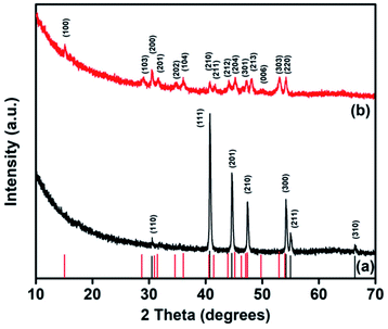 | ||
| Fig. 1 Powder-XRD patterns of the decomposition of Ni(Ac)·4H2O in (a) TOPO/TOP and (b) HDA/TOP at 300 °C for 1 h. | ||
The decomposition of the same precursor (Ni(Ac)2·4H2O) under similar reaction conditions but with HDA in place of TOPO yielded a different phase of nickel phosphide (Fig. 1b), which was indexed to phase-pure hexagonal Ni5P4 (ICDD #01-089-2588) and is henceforth referred to as NiP-2. The formation of NiP-1 or NiP-2 from the decomposition of the same precursor in similar conditions employing TOPO/TOP or HDA/TOP does suggest that the surfactants play a key role in the phase of the formed nickel phosphide. These results are comparable with our earlier study where a dithiophosphonate complex of nickel was employed as a single source precursor to prepare either NiP-1 or NiP-2 particles using TOPO/TOP or HDA/TOP.2 Chemists have played with different surfactants as a tool to influence the phase of formed nickel phosphides while employing Ni(Ac)2·4H2O as the nickel source. For example, the Tatsumisago group36 has reported the formation of NiP2 by refluxing a mixture of Ni(Ac)2·4H2O, TOPO and TOP at 360 °C for 5 hours. Similarly, Ni2P was formed when heating a mixture of the same nickel precursor (Ni(Ac)2·4H2O), TOP, n-octyl ether, and oleylamine at 350 °C for 1 hour.12 The surface adsorption37 and passivation38 effect of surfactants on the prepared nanomaterials have been studied. HDA with a linear structure binds to the surface of the nanoparticles via the lone pair of electrons on the nitrogen atom while the branched TOPO caps the nanoparticles through the lone pair of electrons on the oxygen atom. Moreover, the passivation of the prepared particles by linearly shaped surfactants such as HDA can leave pockets of space during capping, which can lead to surface oxidation,39 unlike branched surfactants (TOPO) that protect the surface of nanoparticles better comparatively, leading to enhanced stability. The surface adsorption and passivation effects of surfactants used in this study (TOPO/HDA) could be one of the factors that explain the formation of different phases of nickel phosphides using the same nickel precursor.
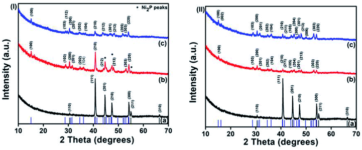
Both phases of nickel phosphides (NiP-1 and NiP-2) were doped with Cu or Mn employing Cu(Ac)2·H2O or Mn(Ac)2 as the metal source, respectively. A careful examination of Cu-doping in Ni2P in TOPO/TOP indicates a gradual phase transformation from Ni2P (NiP-1) to Ni5P4 (NiP-3), as depicted in Fig. 2(I). For instance, the p-XRD peaks of 5% Cu doped NiP-1 indicate the formation of a mixture of phases. The major phase is indexed to Ni5P4 and diffraction peaks of the NiP-1 phase at (201), (210) and (211) [asterisked peaks of Fig. 2(I)b] were also present as a minor phase.
The intensity of the peaks for NiP-1 starts to decrease in 5% Cu doped NiP-1 [Fig. 2(I)b] and disappeared in 10% Cu doping [Fig. 2(I)c], resulting in the phase transformation from Ni2P (NiP-1) to phase-pure hexagonal Ni5P4 (NiP-3) (ICDD #01-089-2588). Furthermore, the absence of any residual peaks of NiP-1 in the transformed NiP-2 suggests the completeness and purity of the transformed phase.
Similarly, replacing Cu with Mn as the dopant in NiP-1, in TOPO/TOP also resulted in the phase transformation from Ni2P (NiP-1) to phase pure Ni5P4 (NiP-4) (ICDD #01-089-2588), as shown in Fig. 2(II). Moreover, the presence of NiP-1 peaks at 5% Mn doping is not observed, unlike with 5% Cu doping [Fig. 2(I) and (II)].
The Ni5P4 XRD peaks at 10% Mn doping are of slightly higher intensity compared to that of 5% Mn doping [Fig. 2(II)b and c] indicative of a complete phase transformation from pure-phase NiP-1 [Fig. 2(II)a] to pure-phase NiP-2 [Fig. 2(II)c]. These p-XRD results indicate a phase transformation from NiP-1 to NiP-2 on doping NiP-1 in TOPO/TOP with 5 and 10% Cu or Mn, where the transformation is rapid in the presence of manganese.
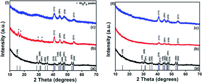
In order to investigate whether the Ni5P4 phase is more flexible to allow the incorporation of dopants, another set of reactions were performed where the Ni5P4 phase was doped with Cu and Mn. Conversely, doping NiP-2 i.e., Ni5P4 formed in HDA/TOP, with 10% Cu yielded nickel phosphide, which was indexed to pure-phase Ni2P (ICDD #03-065-1989) herein referred to as NiP-5 as shown in Fig. 3(I). The phase transformation from NiP-2 (Ni5P4) to NiP-5 (Ni2P) on doping in HDA/TOP with Cu was gradual, just like the reverse phase transformation from Ni2P to Ni5P4 as stated earlier (Fig. 2, 3 and Table 1). The (100), (103) and (201) reflections of the NiP-2 phase [Fig. 3(I)a] are still present in the NiP-5 phase obtained at 5% Cu doping of NiP-2 [Fig. 3(I)b]. There was also a peak at ≈18° of the NiP-2 reflection that was observed for the 5% Cu doping of NiP-2. The complete phase transformation from NiP-2 to NiP-5 is observed at 10% Cu doping [Fig. 3(II)c], since there are no residual peaks of NiP-2. Scheme 1 gives a perspective flow of the formed nickel phosphides in this study and the transformations in the nickel phosphide system induced by transition metal-doping.
| Nickel precursor | Solvents | Dopants | Formed phase |
|---|---|---|---|
| Ni(Ac)2·4H2O | TOPO/TOP | — | NiP-1 (Ni2P) |
| Ni(Ac)2·4H2O | TOPO/TOP | 5% Cu | Ni5P4 + Ni2P |
| Ni(Ac)2·4H2O | TOPO/TOP | 10% Cu | NiP-3 (Ni5P4) |
| Ni(Ac)2·4H2O | TOPO/TOP | 5% Mn | Ni5P4 |
| Ni(Ac)2·4H2O | TOPO/TOP | 10% Mn | NiP-4 (Ni5P4) |
| Ni(Ac)2·4H2O | HDA/TOP | — | NiP-2 (Ni5P4) |
| Ni(Ac)2·4H2O | HDA/TOP | 5% Cu | Ni2P + Ni5P4 |
| Ni(Ac)2·4H2O | HDA/TOP | 10% Cu | NiP-5 (Ni2P) |
| Ni(Ac)2·4H2O | HDA/TOP | 5% Mn | Ni2P |
| Ni(Ac)2·4H2O | HDA/TOP | 10% Mn | NiP-6 (Ni2P) |
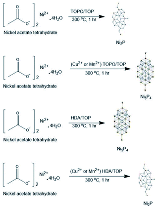 | ||
| Scheme 1 A schematic perspective to formed phosphides and dopant induced phase transformations in this study. | ||
Similarly, we obtained pure Ni2P (NiP-6) on doping NiP-2 (Ni5P4) formed from the decomposition of Ni(Ac)2·4H2O in HDA/TOP with Mn as shown in Fig. 3(II) [ICDD #03-065-1989]. The higher intensity of the XRD peaks of the 10% Mn doping compared to that of 5% doping (Fig. 3(II)b and c) could be indicative of a complete phase transformation from NiP-2 to NiP-6 similar to the reverse transformations stated earlier (Fig. 2). These findings show that the phase transformations from NiP-2 to NiP-6 on doping the NiP-2 formed on the decomposition of Ni(Ac)2·4H2O in HDA/TOP with Cu is gradual, whereas the Mn doping shows a faster transformation comparatively. Table 1 summarizes the nickel phosphides formed from the decomposition of Ni(Ac)2·4H2O in different solvents and the phase transformations in the nickel phosphide system upon doping with different amounts of Cu and Mn.
The structural transformation from one phase to another for transition metal chalcogenides mediated by chemical or thermal means has been reported in the literature,26,36,40,41 though to the best of our knowledge, a phase transformation from one pure phase nickel phosphide to another induced by doping a foreign atom into its crystal lattice has not been reported. In a previous study, Xu et al. also indicated the formation of a mixture of Ni2P and Ni5P4 phases upon Mn-doping via a hydrothermal route, whereas Sarkar et al. observed that the incorporation of Mn induces tensile stress in Ni2P lattice structure.22,42 Saurav et al. similarly demonstrated that the doping of Cu into Pd17Se15via a colloidal route induces tensile stress in the palladium selenide's crystal lattice that subsequently modifies its lattice parameters.43 The incorporation of Mn or Cu into the formed phosphides, therefore may have induced tensile stress in these materials that resulted in the phase transformations observed. The reasons behind the formation of a particular phase and its transformation are not clear or well understood though there have been reports of phase transformations induced by nature of nickel precursor used, phosphorus to nickel ratio, reaction temperature and time or vacant defects generated by the dopants.26,36,40,44 Phosphidating agents such as TOP could therefore play a key role in the diffusion of phosphorus in or out of metals depending on the chemical environment during metal phosphide formation. In the quest to find out the type of stress or defects created by the incorporation of dopants, the decomposition of copper and manganese acetate salts were also explored separately, under similar reaction conditions. The p-XRD analysis of the product obtained after the decomposition of Cu(AC)2·H2O in TOPO/TOP or HDA/TOP showed the formation of face-centered cubic Cu metal (Fig. S1†). Likewise, Mn(AC)2 also didn't form manganese phosphide on decomposition in TOPO/TOP or HDA/TOP, rather the formation of manganese oxide was observed (Fig. S2†). It is pertinent to note that the decomposition of Cu(AC)2·H2O or Mn(AC)2 in TOP alone in the same laboratory conditions also formed Cu or MnO, respectively, as shown in Fig. S1 and S2.† The mixing of two compounds is more feasible when they have similar oxidation states and exist in a similar crystal structure. For example, both Cu3P and Ni2P are hexagonal; therefore Cu3P would have fit easily into the hexagonal lattice structure of Ni2P, causing minimal lattice stress.45 As the dopant metals (Cu and Mn) do not form their respective metal phosphides separately under similar reaction conditions, it is possible that the different products form at the initial stages of the reaction, which may be responsible for creating stress and facilitating the phase transformation. Moreover, the sizes of the dopant ions (Cu2+ or Mn2+) employed in this study may also have an effect on the lattice structure. The size of the Mn2+ (83 pm) dopant, which is larger than Cu2+ (73 pm) as compared to the host Ni2+ (69 pm), plausibly promotes the phase transformation. This may also explain the faster phase transformation in the nickel phosphide system when doping with Mn compared to Cu.
Likewise, the nature of the surfactants employed may also influence the kinetics of the reaction and facilitate the formation of a particular phase. For instance, TOPO or HDA seem to play a key role in promoting or hindering the diffusion of phosphorus into nickel atoms. Hexadecylamine is a much stronger base than TOPO, and may assist in the decomposition of TOP to release phosphorus which is responsible for phosphide formation. Furthermore, the linear structure of HDA, surrounding nickel atoms, is less effective in hindering the diffusion of phosphorus as compared to the bulky and branched TOPO molecule. Therefore, the phosphorus-rich phase (Ni5P4) is favored by HDA, whereas the phosphorus-deficient phase (Ni2P) was obtained in the presence of TOPO. To investigate the role of the surfactants in these phase transformations, we performed these decomposition reactions in TOP alone, following similar experimental conditions. The decomposition of Ni(Ac)2·4H2O in TOP at 300 °C for 1 h formed NiP-1 (ICDD #03-065-1989) as seen in Fig. S3a.† In addition, the decomposition of Ni(Ac)2·4H2O/10% Cu(Ac)2·H2O, and Ni(Ac)2·4H2O/10% Mn(Ac)2 also in TOP only at 300 °C for 1 hour yielded nickel phosphide, which matched well to NiP-1 (ICDD #03-065-1989) as shown in (Fig. S3b and c†). This result indicates that the surfactants (TOPO/HDA) also play a role in the phase transformations we observed in this study.
The morphology of formed and transformed nickel phosphides was studied by scanning electron microscopy (SEM). SEM images show the formation of polydispersed hexagonal disc-shaped particles with some degree of truncated edges for Ni2P formed from the decomposition of Ni(Ac)2·4H2O in TOPO/TOP i.e., NiP-1 (Fig. 4a). The discs which are placed perpendicular to the plane of the paper are observed as elongated or rod-like particles. The defined shape was converted to irregularly shaped particles aggregated together on doping with Cu (NiP-3) and Mn (NiP-4), which resulted in phase transformations (Fig. 4b, c and S4†). The morphology of the Ni5P4 formed from the decomposition of Ni(Ac)2·4H2O in HDA/TOP, i.e., NiP-2 as well as the Cu (NiP-5) and Mn (NiP-6) doped materials was shown by SEM images to be spherical, agglomerated, and well distributed (Fig. 4d–f and S5†).
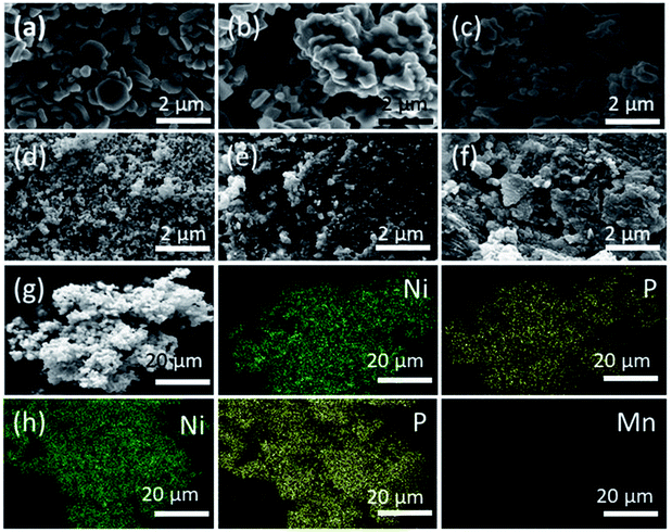 | ||
| Fig. 4 SEM images of (a) NiP-1, (b) NiP-3 (c) NiP-4 (d) NiP-2 (e) NiP-5 and (f) NiP-6. Representative EDX elemental mapping images of (g) NiP-1 and (h) NiP-2. | ||
Transmission electron microscopy (TEM) was employed to further probe the morphology of the formed and transformed phosphides. TEM images confirm the multi-shaped particles formed in NiP-1, NiP-3 and NiP-4 as well as the agglomeration in them as shown in the SEM analysis. It can be seen that the morphology of the initial parent phase and the transformed phase on doping (i.e., NiP-1, NiP-3 and NiP-4), is comparable (Fig. 5a–c). However, changing the surfactant significantly altered the size and morphology of the synthesized materials (Fig. 5d–f). It shows that the reactions performed in a given solvent system (TOPO/TOP or HDA/TOP) have almost similar morphology irrespective of the type of dopants. This kind of morphological conservation on transformation from one material to another has been documented.33,46 Energy-dispersive X-ray spectroscopy (EDX) analysis confirms the composition of the formed phosphides and incorporation of dopants (Cu or Mn) in transformed phosphides' lattices. The SEM-EDX elemental mapping of representative samples (Fig. 4g, h, S5 and S6†) indicate the uniform distribution of Ni, P and the dopants (Cu or Mn). Selected area electron diffraction (SAED) analysis of representative samples was performed to gain insight into the crystallinity of formed and transformed phosphides. Our materials showed well-defined SAED spots, which matched well with the lattice planes of hexagonal Ni2P or Ni5P4 (Fig. 5g–i), indicating crystallinity.
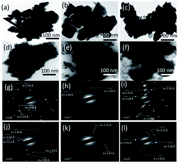 | ||
| Fig. 5 TEM images of (a) NiP-1, (b) NiP-3 (c) NiP-4 (d) NiP-2 (e) NiP-5 and (f) NiP-6. SAED images of (g) NiP-1, (h) NiP-3 (i) NiP-4 (j) NiP-2 (k) NiP-5 and (l) NiP-6. | ||
Electrochemical properties of nickel phosphides for supercapacitor applications
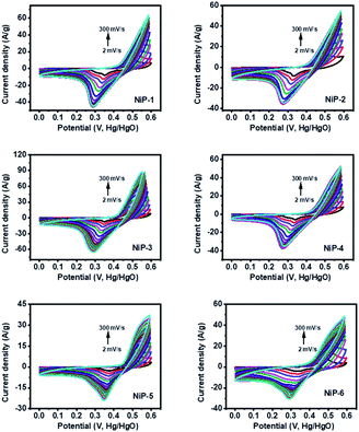
The charge storage capability of formed nickel phosphides (NiP-1 and NiP-2) and the transformed ones (NiP-3 to NiP-6) were studied employing cyclic voltammetry (CV) and galvanostatic charge–discharge (GCD) measurements. The CV profile of all the nickel phosphide electrodes, which is a plot of the current density versus the electric potential of these electrodes, are given in Fig. 6. These CV profiles were recorded in the range of 0–0.6 (V, Hg/HgO) in 3 M KOH electrolyte and at scan rates ranging from 2 to 300 mV s−1. All the nickel phosphide electrodes showed defined redox peaks for the oxidation and reduction processes indicative of typical pseudo-capacitance characteristics.15,47 Also, the CV curves of all the electrodes were maintained even at high scan rates, as shown in Fig. 6, pointing to good redox reversibility.2,48 The specific capacitance of all electrodes was calculated by integrating the plot area within the CV's curve following eqn (1). | (1) |
 is scan rate in V s−1, and ΔV is the potential window in V. It is important to note that the CV curves of NiP-3 showed pairs of distinct redox peaks (anodic peak ≈ +0.55 V and cathodic peak ≈ +0.28 V) corresponding to Ni2+/Ni3+ redox transitions similar to the study by Liu et al.49 All the nickel phosphide electrodes also showed the Ni2+/Ni3+ redox transitions (illustrated in eqn (2) and (3)) typical of faradaic capacitive behavior of the battery-type.
| Ni5P4 + 5OH− ⇌ Ni5P4(OH)5 + 5e− | (2) |
| Ni2P + 2OH− ⇌ Ni2P(OH)2 + 2e− | (3) |
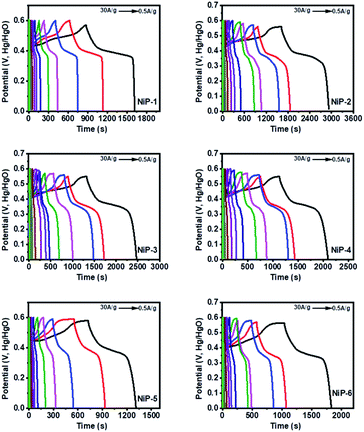
GCD curves of all the nickel phosphide electrodes, which were obtained by analyzing the electrochemical performance of these electrodes in terms of potential (V, Hg/HgO) versus time (s) was employed to further probe the electrodes' capacitive behavior. The GCD profiles (Fig. 7) showed typical pseudo-capacitance behavior for all the electrodes which is in agreement with the CV results. NiP-2 showed the highest calculated specific capacitance of 1325 F g−1 at 2 A g−1. The rate performance of NiP-2, however, dropped to 102 F g−1 as the charge and discharge current density increased to 30 A g−1. It is pertinent to note that NiP-3 (Ni5P4 formed on doping Ni2P with 10% Cu) with a calculated specific capacitance of 1209 F g−1 at 1 A g−1 had a better rate performance of 382 F g−1 at 30 A g−1, which was the highest among the other samples at the same current density. It can be inferred from these results that Ni5P4 has better storage capacity compared to Ni2P and that the presence of Cu in Ni5P4 dramatically improved its charge retention capacity even with an increase in the current density. The electrostatic interaction of Cu2+ with the P![[double bond, length as m-dash]](https://www.rsc.org/images/entities/char_e001.gif) O group of the branched surfactant TOPO plausibly maintained the redox process of NiP-3 at a high current density. The variation of specific capacitance and discharge current and the Ragone plot, a variation of energy density and power density for all the electrodes, are given in Fig. 8. Lu et al. prepared Ni2P coated with Ni by an electroless process with a calculated specific capacitance of 464 F g−1, which our NiP-2 electrode (1325 F g−1) outperformed by 65%.50 Similarly, the NiP-3 electrode (1209 F g−1) showed better storage capacity compared to our earlier report of Ni2P, Co–Ni2P (864 F g−1) and Fe–Ni2P (856 F g−1).15
O group of the branched surfactant TOPO plausibly maintained the redox process of NiP-3 at a high current density. The variation of specific capacitance and discharge current and the Ragone plot, a variation of energy density and power density for all the electrodes, are given in Fig. 8. Lu et al. prepared Ni2P coated with Ni by an electroless process with a calculated specific capacitance of 464 F g−1, which our NiP-2 electrode (1325 F g−1) outperformed by 65%.50 Similarly, the NiP-3 electrode (1209 F g−1) showed better storage capacity compared to our earlier report of Ni2P, Co–Ni2P (864 F g−1) and Fe–Ni2P (856 F g−1).15
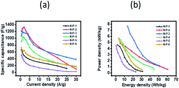 | ||
| Fig. 8 (a) Variation of specific capacitance as a function of current density and (b) Ragone plots for the nickel phosphide samples. | ||
Our nickel phosphide electrodes, therefore, showed better or competitive charge storage capacity in comparison to other similar reports (Table S1†).
The wide-scale application of supercapacitors is usually constrained by low energy density. We, therefore, calculated the energy density and power density of our electrodes using the following equations.
 | (4) |
 | (5) |
The NiP-3 electrode gave the highest power density of 7.5 kW kg−1 and a calculated energy density of 51 W h kg−1. The highest energy density of 60 W h kg−1 was, however, obtained from the NiP-2 electrode.
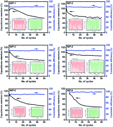
We also measured the long-term charge retention stability of our phosphide electrodes since this could limit their practical application and is presented in Fig. 9.
All the nickel phosphide electrodes showed an excellent charge retention capacity of ≈99% even after 5000 cycles, suggestive of good cyclic stability. The CV and GCD measurements, therefore, indicate that formed nickel phosphides are electroactive materials employable in energy storage applications and that phase transformation on Cu doping in TOPO/TOP improves this process.
Water splitting applications of nickel phosphide electrodes
Kucernak and Sundaram51 prepared nickel phosphides, Ni2P and Ni12P5, by a mechano-chemical and hydrothermal route which required approximate overpotentials of 270 and 450 mV to reach a current density of 10 mA cm−2, respectively which are outperformed by all our electrodes with our NiP-5 electrode (146 mV) outperforming them by 58 and 68%, respectively. Similarly, our nickel phosphide electrodes recorded lower overpotentials to deliver 10 mA cm−2 current density compared to nickel phosphide electrodes prepared by Yan et al. that required 310 mV to reach the same current density.55 Pristine Ni2P and doped-Ni2P (Co–Ni2P, Fe–Ni2P) prepared by the hot injection route in our earlier study needed overpotentials of 164, 158 and 202 mV to deliver a current density of 10 mA cm−2 which is comparable to this study.15 Similarly, bare dinickel phosphide recently prepared by a solvent-less route delivered a current density of 10 mA cm−2 with an overpotential of 174 mV comparable to our nickel phosphides.3 Table S2† summarizes the HER performance of our electrodes in comparison to other nickel phosphides which indicates that our electrodes outperform or compare well with them.
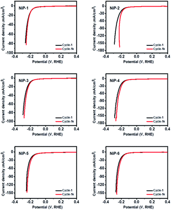
The durability and long-term stability of an electrode are crucial factors necessary for the practical use of HER technologies.56 We, therefore, investigated the long-term stability of our nickel phosphide electrodes by measuring their polarization curves which are given in Fig. 11. The polarization curves for all the electrodes in the 1st and 1000th cycles of recycling CV measurements show negligible deviation. A closer examination of the cycles for pristine Ni5P4 (NiP-2) and the doped-Ni5P4 (NiP-5 and NiP-6 obtained by phase transformation) indicate better electrode durability on phase transformation. These similar LSV-CV curves (Fig. 11) indicate that our electrodes maintained their electrochemical behavior for different cycles pointing to electrochemical stability and robusticity. We also analysed the powder XRD patterns of our catalysts prior to and after the HER tests to gain further insight into the stability of our nickel phosphide catalysts with the representative results given in Fig. S8.† These analyses clearly show that our catalysts are stable with similar XRD patterns prior to and after HER.
NiP-5 had the lowest Tafel slope of 54 mV dec−1 among all the samples, indicative of the fastest reaction kinetics. Therefore NiP-3 was a better catalyst in overcoming the thermodynamic barrier for OER while NiP-5 catalyst had the fastest reaction kinetics. Furthermore, phase transformation upon Cu and Mn doping, therefore, improved the nickel phosphides' reaction kinetics. The lower overpotential of NiP-3 (Ni5P4, 10% Cu) may be attributed to the presence of Cu in the Ni5P4 lattice, which probably leads to more exposed active sites for the adsorption of OH− species for the formation of O2.57 This may be due to the fact that doping a foreign atom into a host material lattice generally alters its electronic and atomic environment.58 Furthermore, documented reports59,60 indicate that the stretching or compression of atoms in the lattice of a catalyst induced by doping that leads to strain improves a catalyst's OER activity. The probable strain in the transformed nickel phosphides on doping Cu and Mn improves the catalyst's OER activity. It is important to note that NiP-3 with the slowest reaction kinetics (85 mV dec−1) among all the samples has a faster reaction kinetics than the state-of-art IrO2 for OER which is ≈124.5 mV dec−1. Additionally, our nickel phosphide electrodes compare well or outperform other reported nickel phosphides (Table S3†).
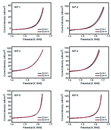
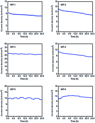
The practical application of an electrode for OER is a function of its long-term stability and durability. The LSV-CV curves of all the electrodes for the 1st and 1000th cycles were therefore measured and are given in Fig. 13. These LSV curves matched well, indicating good stability. Also, the stability of all materials as OER catalysts was studied using chronoamperometry (CA) measurements at a constant voltage of 0.55 V for 25 h. As shown in Fig. 14, all electrodes maintained a high current for an extended time. NiP-3 displayed the highest current density value of 27.5 mA cm−2 and a stable current through the experiment, indicating excellent electrochemical stability. Moreover, Fig. 14 also indicates that phase transformation in the nickel phosphide system improved the catalyst's durability and stability. Powder XRD pattern examinations of our nickel phosphides prior to and after OER also indicated catalysts stability as well as robusticity which is given by a representative example in Fig. S9.†
This experiment, therefore, demonstrated that our nickel phosphide electrodes could maintain their performance for an extended period. It is important to note that the slight fluctuations observed in some of the plots are related to the bubbling of O2 that is released during the OER process.3
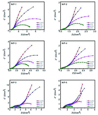
The electrochemical impedance spectroscopy (EIS) measurements for all the electrodes were also performed to gain further insight into the effect of phase transformations in the nickel phosphide system upon doping with transition metals. These EIS measurements in the form of Nyquist plots (Fig. 15) were therefore obtained by applying a frequency range from 0.05 Hz to 10 kHz along with the applied alternate current amplitude of 10 mV. Also, the electric potentials of 0.45, 0.5, 0.55, and 0.6 V for each sample were employed using a saturated calomel electrode (SCE) as reference. The diameter of the semicircle or arc is directly related to the resistance of the charge transfer process, meaning that a smaller diameter gives a lower charge transfer resistance.58 The resistance measurements of all the electrodes in decreasing order is NiP-1 > NiP-5 > NiP-3 > NiP-4 > NiP-2 > NiP-6. Hence doping NiP-1 with Cu (NiP-3) and Mn (NiP-4), decreased the charge transfer resistance, as shown in Fig. 15. NiP-6 showed the best electron transfer process among the other electrodes. Similarly, doping NiP-2 (Ni5P4 formed by the decomposition of Ni(Ac)2·4H2O in HDA/TOP) with Mn (NiP-6), which transformed Ni5P4 to Ni2P decreased the EIS measurements comparatively. Only NiP-5 (Ni5P4 formed on Cu doping of Ni2P) electrode among all the electrodes did not decrease the EIS measurements compared to the pristine phosphides. Moreover, it is important to note that NiP-5 and NiP-6 Nyquist plots showed two arcs, as seen in Fig. 15, which was also observable in our previous study.15 When this behavior occurs, it means that the arc at high frequency represents the charge transfer resistance, which was observed in all the electrodes, whereas the arc at lower frequencies is related to mass transfer resistance.61 Therefore, NiP-6 electrode among all samples offered the lowest charge transfer resistance and phase transformations in the nickel phosphide system induced by transition metal doping decreased this charge transfer resistivity.
Considering all the OER performance indicators, we can therefore conclude that phase transformations in the nickel phosphide system upon doping with transition metals (Cu & Mn) resulted in better OER activity, performance, and stability, with the NiP-3 electrode having the best performance.
Conclusion
Different phases of nickel phosphides (Ni2P and Ni5P4) can be prepared by the decomposition of Ni(AC)2·4H2O by a colloidal route (TOPO/TOP or HDA). The employed solvents and incorporation of transition metal (Cu or Mn) as dopants, results in either phase transformations (Ni2P to Ni5P4 or Ni5P4 to Ni2P) or formation of mixture of phases (Ni2P/Ni5P4). The probable reasons for these rare transformations are discussed. The performance of pristine and transformed nickel phosphides as electrocatalysts was investigated for overall water splitting reactions, where the phase transformation resulted in an improved electrode's catalytic activity and durability. Upon doping with Cu, the transformed nickel phosphide phases showed the lowest overpotentials for both HER and OER (i.e., current density of 10 mA cm−2 was achieved at an overpotential of 146 mV for HER and overpotential of 276 mV for the OER at the same current density). NiP-2 had the highest calculated specific capacitance of 1325 at 2 A g−1. All electrodes showed good stability and durability, which are crucial to practical application in green hydrogen generation technologies.Author contributions
Gwaza E. Ayom: conceptualization, investigation, methodology, writing-original draft, writing-review and editing. Malik D. Khan: conceptualization, validation, writing-review and editing. Siphamandla C. Masikane: data acquisition for SEM & TEM. Felipe M. de Souza: writing-the electrochemical part. Wang Lin: data acquisition for the electrochemical part. Ram Gupta: writing-review of the electrochemical part and supervision of electrochemical data acquisition. Neerish Revaprasadu: supervision, funding acquisition, resources and writing-editing.Conflicts of interest
There are no conflicts to declare.Acknowledgements
The authors are grateful to the National Research Foundation (NRF) South African Research Chairs Initiative (SARChI) for financial support. A. G. E. thanks the University of Zululand and NRF for a research fellowship. M. D. K. thanks the European Union's Horizon 2020 research and innovation programme under the Marie Sklodowska-Curie grant agreement no. 847413 for funding. Scientific work published as part of an international co-financed project funded from the programme of the Minister of Science and Higher Education entitled “PMW” in the years 2020–2024; agreement no. 5005/H2020-MSCA-COFUND/2019/2. RKG also thanks Pittsburg State University and Kansas Polymer Research Center for providing infrastructure.References
- W. Li, M. Wu, P. Shi, T. Li, H. Yue, Z. Dong, Y. Gao and X. Lou, Electrochim. Acta, 2020, 331, 135440 CrossRef CAS.
- G. E. Ayom, M. D. Khan, T. Ingsel, W. Lin, R. K. Gupta, S. J. Zamisa, W. E. van Zyl and N. Revaprasadu, Chem.–Eur. J., 2020, 26, 2693–2704 CrossRef CAS PubMed.
- G. E. Ayom, M. D. Khan, G. B. Shombe, J. Choi, R. K. Gupta, W. E. van Zyl and N. Revaprasadu, Inorg. Chem., 2021, 60, 11374–11384 CrossRef CAS PubMed.
- M. Dilshad Khan, S. U. Awan, C. Zequine, C. Zhang, R. K. Gupta and N. Revaprasadu, ACS Appl. Energy Mater., 2020, 3(2), 1448–1460 CrossRef.
- P. Kannan, T. Maiyalagan, B. Lin, W. Lei, C. Jie, L. Guo, Z. Jiang, S. Mao and P. Subramanian, Talanta, 2020, 209, 120511 CrossRef CAS PubMed.
- U. Guharoy, T. Ramirez Reina, E. Olsson, S. Gu and Q. Cai, ACS Catal., 2019, 9, 3487–3497 CrossRef CAS.
- S. Zhang, G. Gao, H. Zhu, L. Cai, X. Jiang, S. Lu, F. Duan, W. Dong, Y. Chai and M. Du, Sci. Bull., 2020, 65, 640–650 CrossRef CAS.
- Z. Zhu, J. Hao, H. Zhu, S. Sun, F. Duan, S. Lu and M. Du, Adv. Fiber Mater., 2021, 3, 117–127 CrossRef.
- A. Ray, S. Sultana, L. Paramanik and K. M. Parida, J. Mater. Chem. A, 2020, 8, 19196–19245 RSC.
- C. Hu, C. Lv, S. Liu, Y. Shi, J. Song, Z. Zhang, J. Cai and A. Watanabe, Catalysts, 2020, 10, 188 CrossRef CAS.
- Y. Gan, C. Wang, X. Chen, P. Liang, H. Wan, X. Liu, Q. Tan, H. Wu, H. Rao and H. Wang, Chem. Eng. J., 2020, 392, 123661 CrossRef CAS.
- H. Kim, S. Surendran, Y. Chae, H. Y. Lee, T.-Y. An, H. S. Han, W. Park, J. K. Kim and U. Sim, Appl. Surf. Sci., 2020, 511, 145424 CrossRef CAS.
- J. Liu, X. Chen, M. Shao, C. An, W. Yu and Y. Qian, J. Cryst. Growth, 2003, 252, 297–301 CrossRef CAS.
- S. Yang, G. Chen, A. G. Ricciardulli, P. Zhang, Z. Zhang, H. Shi, J. Ma, J. Zhang, P. W. Blom and X. Feng, Angew. Chem., Int. Ed., 2020, 59, 465–470 CrossRef CAS PubMed.
- G. E. Ayom, M. D. Khan, J. Choi, R. K. Gupta, W. E. van Zyl and N. Revaprasadu, Dalton Trans., 2021, 50(34), 11821–11833 RSC.
- W. Han, X. Li, B. Liu, L. Li, H. Tang, Y. Li, C. Lu and X. Li, Chem. Commun., 2019, 55, 9279–9282 RSC.
- G. E. Ayom, M. D. Khan, G. B. Shombe, J. Choi, R. K. Gupta, W. E. van Zyl and N. Revaprasadu, Inorg. Chem., 2021, 60(15), 11374–11384 CrossRef CAS PubMed.
- J. F. Callejas, C. G. Read, C. W. Roske, N. S. Lewis and R. E. Schaak, Chem. Mater., 2016, 28, 6017–6044 CrossRef CAS.
- C. Guo, X. Liu, L. Gao, X. Kuang, X. Ren, X. Ma, M. Zhao, H. Yang, X. Sun and Q. Wei, Appl. Catal., B, 2020, 263, 118296 CrossRef CAS.
- J. Xu, Z. Liu, Z. Wei, S. Zhang, C. Guo and M. He, Electrochim. Acta, 2020, 136417 CrossRef CAS.
- C. Wei, X. Fan, X. Deng, L. Ma, X. Zhang, Q. Liu and J. Guo, Sustainable Energy Fuels, 2020, 4, 1883–1890 RSC.
- S. Xu, Y. Du, X. Liu, X. Yu, C. Teng, X. Cheng, Y. Chen and Q. Wu, J. Alloys Compd., 2020, 154210 CrossRef CAS.
- Y. Zhang, L. Sun, L. Bai, H. Si, Y. Zhang and Y. Zhang, Nano Res., 2019, 12, 607–618 CrossRef CAS.
- W. S. Leong, Nature, 2020, 577, 477–478 CrossRef CAS PubMed.
- H. Asayesh-Ardakani, A. Nie, P. M. Marley, Y. Zhu, P. J. Phillips, S. Singh, F. Mashayek, G. Sambandamurthy, K.-b. Low and R. F. Klie, Nano Lett., 2015, 15, 7179–7188 CrossRef CAS PubMed.
- Y.-R. Zheng, P. Wu, M.-R. Gao, X.-L. Zhang, F.-Y. Gao, H.-X. Ju, R. Wu, Q. Gao, R. You and W.-X. Huang, Nat. Commun., 2018, 9, 1–9 CrossRef PubMed.
- D. Voiry, H. Yamaguchi, J. Li, R. Silva, D. C. Alves, T. Fujita, M. Chen, T. Asefa, V. B. Shenoy and G. Eda, Nat. Mater., 2013, 12, 850–855 CrossRef CAS PubMed.
- M. A. Lukowski, A. S. Daniel, F. Meng, A. Forticaux, L. Li and S. Jin, J. Am. Chem. Soc., 2013, 135, 10274–10277 CrossRef CAS PubMed.
- H. Huang, X. Fan, D. J. Singh and W. T. Zheng, Nanoscale, 2020, 12(3), 1247–1268 RSC.
- D. Pariari, R. M. Varma, M. N. Nair, P. Zeller, M. Amati, L. Gregoratti, K. K. Nanda and D. Sarma, Appl. Mater. Today, 2020, 19, 100544 CrossRef.
- S. Demirci, H. H. Gürel, J. Seymur and S. Ciraci, Nanoscale, 2020, 12(5), 3249–3258 RSC.
- G. B. Shombe, M. D. Khan, C. Zequine, C. Zhao, R. K. Gupta and N. Revaprasadu, Sci. Rep., 2020, 10, 1–14 CrossRef PubMed.
- E. Muthuswamy and S. L. Brock, Chem. Commun., 2011, 47, 12334–12336 RSC.
- S. Lu, H. Xu, B. Gao and L. Ren, New J. Chem., 2017, 41, 8497–8502 RSC.
- H. Xu, S. Lu and L. Ren, Mater. Res. Express, 2016, 3, 105010 CrossRef.
- K. Aso, A. Hayashi and M. Tatsumisago, Inorg. Chem., 2011, 50, 10820–10824 CrossRef CAS PubMed.
- W. Wang, B. Gu and L. Liang, J. Dispersion Sci. Technol., 2005, 25, 593–601 CrossRef.
- I. Csik, S. P. Russo and P. Mulvaney, J. Phys. Chem. C, 2008, 112, 20413–20417 CrossRef CAS.
- W. W. Yu, Y. A. Wang and X. Peng, Chem. Mater., 2003, 15, 4300–4308 CrossRef CAS.
- D. Li, K. Senevirathne, L. Aquilina and S. L. Brock, Inorg. Chem., 2015, 54, 7968–7975 CrossRef CAS PubMed.
- P. Chen, K. Xu, S. Tao, T. Zhou, Y. Tong, H. Ding, L. Zhang, W. Chu, C. Wu and Y. Xie, Adv. Mater., 2016, 28, 7527–7532 CrossRef CAS PubMed.
- S. Sarkar, L. Dheer, C. Vinod, R. Thapa, U. V. Waghmare and S. C. Peter, ACS Appl. Energy Mater., 2020, 3, 1271–1278 CrossRef CAS.
- S. C. Sarma, V. Mishra, K. A. Ann Mary, S. Roy and S. C. Peter, ACS Energy Lett., 2018, 3, 3008–3014 CrossRef CAS.
- E. Muthuswamy, G. H. L. Savithra and S. L. Brock, ACS Nano, 2011, 5, 2402–2411 CrossRef CAS PubMed.
- L. Yu, J. Zhang, Y. Dang, J. He, Z. Tobin, P. Kerns, Y. Dou, Y. Jiang, Y. He and S. L. Suib, ACS Catal., 2019, 9, 6919–6928 CrossRef CAS.
- A. E. Henkes and R. E. Schaak, Inorg. Chem., 2008, 47, 671–677 CrossRef CAS PubMed.
- D. Guragain, C. Zequine, R. Bhattarai, J. Choi, R. K. Gupta, X. Shen and S. R. Mishra, MRS Adv., 2020, 5, 2487–2494 CrossRef CAS.
- I. Rabani, J. Yoo, C. Bathula, S. Hussain and Y.-S. Seo, J. Mater. Chem. A, 2021, 9, 11580–11594 RSC.
- S. Liu, K. V. Sankar, A. Kundu, M. Ma, J.-Y. Kwon and S. C. Jun, ACS Appl. Mater. Interfaces, 2017, 9, 21829–21838 CrossRef CAS PubMed.
- Y. Lu, J.-k. Liu, X.-y. Liu, S. Huang, T.-q. Wang, X.-l. Wang, C.-d. Gu, J.-p. Tu and S. X. Mao, CrystEngComm, 2013, 15, 7071–7079 RSC.
- A. R. Kucernak and V. N. N. Sundaram, J. Mater. Chem. A, 2014, 2, 17435–17445 RSC.
- K. Yan, S. K. Kim, A. Khorshidi, P. R. Guduru and A. A. Peterson, J. Phys. Chem. C, 2017, 121, 6177–6183 CrossRef CAS.
- H. Zhu, G. Gao, M. Du, J. Zhou, K. Wang, W. Wu, X. Chen, Y. Li, P. Ma and W. Dong, Adv. Mater., 2018, 30, 1707301 CrossRef PubMed.
- I. Roger, R. Moca, H. N. Miras, K. G. Crawford, D. A. Moran, A. Y. Ganin and M. D. Symes, J. Mater. Chem. A, 2017, 5, 1472–1480 RSC.
- L. Yan, P. Dai, Y. Wang, X. Gu, L. Li, L. Cao and X. Zhao, ACS Appl. Mater. Interfaces, 2017, 9, 11642–11650 CrossRef CAS PubMed.
- Y. Wen, Z. Zhuang, H. Zhu, J. Hao, K. Chu, F. Lai, W. Zong, C. Wang, P. Ma and W. Dong, Adv. Energy Mater., 2021, 11, 2102138 CrossRef CAS.
- B. Qiu, L. Cai, Y. Wang, Z. Lin, Y. Zuo, M. Wang and Y. Chai, Adv. Funct. Mater., 2018, 28, 1706008 CrossRef.
- J. Kundu, S. Khilari, K. Bhunia and D. Pradhan, Catal. Sci. Technol., 2019, 9, 406–417 RSC.
- N. Ma, N. Li, T. Wang, X. Ma and J. Fan, J. Mater. Chem. A, 2021, 10(3), 1390–1401 RSC.
- X. Gao, Y. Zhou, Y. Tan, S. Liu, Z. Cheng and Z. Shen, Phys. Chem. Chem. Phys., 2020, 22, 2457–2465 RSC.
- Q.-A. Huang, R. Hui, B. Wang and J. Zhang, Electrochim. Acta, 2007, 52, 8144–8164 CrossRef CAS.
Footnote |
| † Electronic supplementary information (ESI) available: Powder-XRD patterns, SEM images and SEM-EDX elemental mapping images of formed materials and comparison tables for HER, OER and supercapacitance. See DOI: 10.1039/d1se01866c |
| This journal is © The Royal Society of Chemistry 2022 |

