 Open Access Article
A fourteen-component high-entropy alloy@oxide bifunctional electrocatalyst with a record-low ΔE of 0.61 V for highly reversible Zn–air batteries†
Zeyu
Jin
ad,
Xuyan
Zhou
ad,
Yixuan
Hu
b,
Xiaowei
Tang
c,
Kailong
Hu
ad,
Kolan Madhav
Reddy
*b,
Xi
Lin
*ade and
Hua-Jun
Qiu
 *ad
*ad
aSchool of Materials Science and Engineering, Harbin Institute of Technology, Shenzhen, 518055, China. E-mail: qiuhuajun@hit.edu.cn; linxi@hit.edu.cn
bFrontier Research Center for Materials Structure, School of Materials Science and Engineering, Shanghai Jiao Tong University, Shanghai, 200240, China. E-mail: kmreddy@sjtu.edu.cn
cMathematical School, Qilu Normal University, Jinan, 250200, China
dBlockchain Development and Research Institute, Harbin Institute of Technology, Shenzhen 518055, P. R. China
eState Key Laboratory of Advanced Welding and Joining, Harbin Institute of Technology, Shenzhen 518055, China
First published on 24th August 2022
Abstract
Nanostructured high-entropy materials such as alloys, oxides, etc., are attracting extensive attention because of their widely tunable surface electronic structure/catalytic activity through mixing different elements in one system. To further tune the catalytic performance and multifunctionality, the designed fabrication of multicomponent high-entropy nanocomposites such as high-entropy alloy@high-entropy oxides (HEA@HEO) should be very promising. In this work, we design a two-step alloying–dealloying strategy to synthesize ultra-small HEA nanoclusters (∼2 nm) loaded on nanoporous HEO nanowires, and the compositions of both the HEA and HEO can be adjusted separately. To demonstrate this concept, a seven-component HEA (PtPdAuAgCuIrRu) clusters@seven-component HEO (AlNiCoFeCrMoTi)3O4 was prepared, which is highly active for both oxygen evolution and reduction reactions. Our comprehensive experimental results and first-principles density functional theory (DFT) calculations clearly show that better oxygen evolution reaction (OER) performance is obtained by optimizing the composition of the HEO support, and the seven-component HEA nanocluster is much more active for the ORR when compared with pure Pt due to the modified surface electronic structure. Specifically, the high-entropy composite exhibits an OER activity comparable to the best reported value, and the ORR activity exceeded the performance of commercial Pt/C in alkaline solutions with a record-low bifunctional ΔE of 0.61 V in 0.1 M KOH solution. This work shows an important route to prepare complex HEA@HEO nanocomposites with tuned catalytic performance for multifunctional catalysis and energy conversion.
1. Introduction
Noble metals play an important role in the field of industrial catalysis and energy conversion.1–4 For example, Pt has outstanding oxygen reduction reaction (ORR) and hydrogen evolution reaction (HER) catalytic performance, while Ru and Ir have excellent oxygen evolution reaction (OER) activity.5–8 As their high price and scarce reserves severely hinder their widespread application, researchers have been making great efforts to reduce noble metal loading and to enhance their catalytic performance. Recently, noble metal-based clusters with a size of less than 2 nm have attracted much attention due to their high material utilization efficiency, abundant unsaturated active sites, unique electronic structures, and high catalytic performance in many reactions.9 Compared with unary or binary nanoclusters, high-entropy alloy (HEA) nanoclusters composed of five or more metal elements can further reduce the content of noble metals because of the incorporation of non-noble ones, and also have better phase stability due to the high-entropy effect.10–14 Moreover, owing to the adjustable electronic structure through different atom interactions, HEA clusters exhibit tunable catalytic activity and even synergistic catalytic performance.15–33 For example, Yao et al. synthesized PtPdRhRuCe and CoMoFeNiCu nanoparticles (NPs) using a carbothermal shock method, which exhibited outstanding performance in the ammonia oxidation reaction.34 Li et al. prepared small size PtNiFeCoCu NPs (3–4 nm) by a low temperature oil phase synthesis method and used it for the alkaline hydrogen evolution reaction and methanol oxidation reaction.35 Wu et al. reported a one-pot polyol process to prepare RuRhPdIrPt NPs, which exhibited a high HER activity.36It is worth noting that the catalytic performance, multifunctionality and durability of the catalyst system are highly dependent on suitable supportive nanostructures.37 We noted that most reported studies on noble metal clusters use nano-carbon materials as substrates.38–40 Despite the observed outstanding catalytic activity, the interface between metal clusters and carbon substrates is not very stable due to the relatively weak interfacial binding strength.41 When participating in catalysis under long-term operation or under harsh conditions, the agglomeration of nanoparticles may occur, and the activity of the catalyst will gradually weaken or even disappear.37,38 On the other hand, the carbon support is usually inert for most reactions.
Compared with normally used carbon-based supports, multicomponent non-noble metal-based high-entropy oxides (HEOs) have some unique properties. For example, HEO supports are highly designable, composition tunable and catalytically active, which can make the HEA cluster/HEO nanocomposite highly stable and multifunctional.33,42,43 Moreover, DFT calculations have shown that the electronic interaction between some non-noble metal oxides such as Fe, Cr, Ni, etc., and noble metals would result in a synergistic catalytic effect and enhanced catalytic activity of the whole system.26,27,37 However, the straightforward and scalable fabrication of an inherently contacted HEA cluster@HEO nanocomposite with separately tuned element composition of both HEA and HEO is still very challenging considering the super complexity of the nano-system.
In this work, we innovatively developed a simple and effective two step alloying–dealloying strategy to realize the fabrication of HEA cluster@HEO. This strategy is also highly controllable in the compositions of both HEA and HEO supports and highly scalable without the use of any organic components. To demonstrate this concept, we designed and prepared seven-component HEA nanoclusters (PtPdAuAgCuIrRu) supported on seven-component nanostructured spinel HEO (AlNiCoFeCrMoTi) for the first time. The HEA clusters with particle sizes of about 1.5–2 nm were uniformly dispersed and inherently contacted with the HEO support, which results in high stability of the HEA nanoclusters. In order to achieve a high bifunctional activity, we optimized the composition of the HEO support to achieve a high OER activity. Our experimental results show that better OER performance can be obtained by optimizing the structure of the HEO substrate, and the incorporation of HEA nanoclusters makes the composite highly ORR active. When using the high-entropy composite as a bifunctional cathode in an Zn–air battery, it also shows an excellent charge–discharge reversibility with a record-low ΔE of 0.61 V, even 20 mV smaller than the reported best 0.63 V in 0.1 M KOH solution.44 This study provides a new strategy to fabricate a multicomponent composite catalyst with multifunctionality, tunability and high durability due to the tunable surface electronic structure for both HEA clusters and HEO supports.
2. Results and discussion
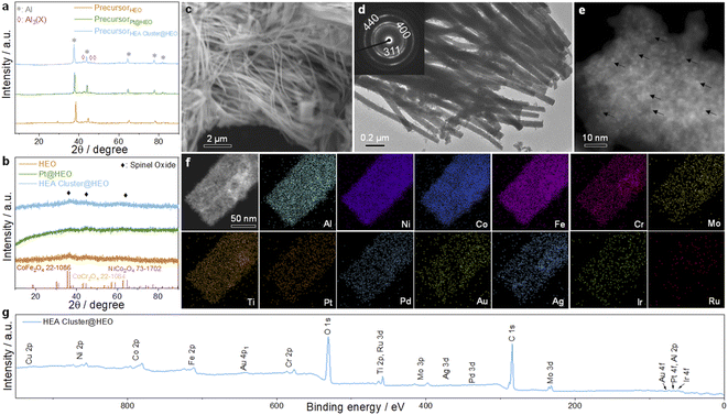
The schematic illustration of the fabrication process of the HEA cluster@HEO composite is shown in Scheme 1. Energy-dispersive X-ray spectrometry (EDS) was firstly utilized to confirm that the 14 elements are successfully integrated into the nanocomposite based on the designed ratios (Fig. S1†). X-ray diffraction (XRD) was used to study the crystal structure change of the alloy before and after dealloying. As shown in Fig. 1a, the precursor alloy shows characteristic peaks at about 38.3°, 44.7°, 65.1°, 78.2° and 82.5°, corresponding to the pure aluminum phase in the precursor alloy. Additionally, some weak peaks at about 43°, 46.3° and 47.5° can be assigned to the Al3X (X: NiCoFeCrMoTi) phase in the alloy (Fig. 1a). After dealloying, all the peaks from pure Al and Al3X phases disappeared, and a flat diffraction curve appears, indicating the formation of a nanoscale crystalline material. Several weak peaks at about 36°, 43° and 64° can be assigned to spinel structured oxides such as CoFe2O4, NiCo2O4 and CoCr2O4 (Fig. 1b). We found that a small amount of noble metal incorporation has no obvious effect on the phase composition of the alloy both before and after dealloying according to the XRD analysis (Fig. 1b).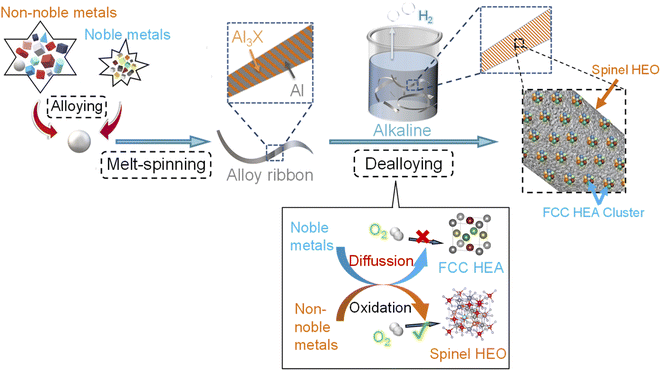 | ||
| Scheme 1 Schematic illustration of the whole process for the preparation of the HEA nanoclusters supported on HEO. | ||
The scanning electron microscopy (SEM) image indicates that the as-prepared HEA cluster@HEO shows a nanowire structure with diameters of ∼50–100 nm (Fig. 1c). This is due to the formation of a nanowire structured Al3(NiCoFeCrMoTi) intermetallic phase mixed with the Al phase during the alloy preparation process.26,45 Transmission electron microscope (TEM) images further indicated that the diameter of the nanowires is about 50 nm to 100 nm (Fig. 1d). A high-resolution TEM (HRTEM) image verifies the formed nanoscale crystals within the nanowires (Fig. S3†). The diffraction fringe spacing is 2.45 Å, representing the (311) plane of the spinel phase, which is in agreement with the XRD results. The HRTEM result combined with selected area electron diffraction (SAED) data (inset in Fig. 1d) further demonstrates the spinel HEO nanostructures and their polycrystalline nature. Moreover, the clear color contrast of the nanowires with an uneven surface from the HRTEM image indicates the formation of nanopores or holes during etching of Al (Fig. S4†). This explains the detected ultrafine pore size of less than 5 nm by a N2 adsorption/desorption test (Fig. S2†). Additionally, the STEM image (Fig. 1e) confirms the uniform distribution of distinguishable nanoclusters on the HEO nanowires (some are marked by black arrows). According to the STEM-EDS elemental mapping (Fig. 1f), all 14 elements are uniformly distributed on the nanowires (Cu is not shown due to the interference from the TEM Cu substrate). Due to the low contents of noble elements, their mapping contrasts are relatively weak compared with the non-noble ones. The formation of HEA cluster@HEO materials during dealloying is mainly due to differences in the metallicity of these elements in the precursors. Metal elements with standard redox potentials lower than copper will be oxidized during etching Al and forming a multicomponent HEO support. These noble ones would diffuse and form HEA nanoclusters inherently decorated on the HEO.
We then use X-ray photoelectron spectroscopy (XPS) to study the chemical states of the 14 elements in the HEA cluster@HEO. Fig. 1g shows the complete XPS spectrum for the HEA cluster@HEO sample in the range of 0–950 eV, revealing the presence of the 14 constituent elements. When dealloying Al with alkaline aqueous solutions, these chemically active transition metals (Ni, Co, Fe, Cr, Ti, and Mo) will be oxidized to form multicomponent HEOs. Noble metals (Pt, Pd, Au, Ag, etc.) will retain their metallic state, thus forming the HEA@HEO metal/oxide composite. Specifically, the spectrum of Al 2p indicates that the remaining Al is basically in the state of Al3+ with the peak located at 74.2 eV (Fig. S5†). Ni exists as Ni2+ with the peaks located at 855.9 eV and 874.3 eV. For Co 2p, the peaks at ∼780.7 and 796.7 eV can be assigned to Co2+ 2p3/2 and Co2+ 2p1/2, respectively. Fe exists in the states of Fe3+ 2p with the peaks located at 710.3 eV and 723.5 eV. As for Cr 2p, the two main peaks at 576.5 eV and 586.2 eV can be identified as Cr3+ 2p3/2 and Cr3+ 2p1/2, respectively. For Mo 2p, Mo6+ is the main oxidation state with the peaks located at 231.8 eV and 234.8 eV. Ti mainly exists in the oxidized state of Ti4+, with the peaks located at around 457.8 eV and 463.4 eV. For the noble elements, the peaks of Pt can be identified as Pt0 located at 67.6 eV and 73.5 eV. Metallic Pd's peaks are located at 334.7 eV and 339.2 eV. Au mainly exists in the form of Au0 4f7/2 (83.3 eV) and Au0 4f5/2 (87.1 eV). The peaks of Ag are assigned to Ag0 3d5/2 (367.5 eV) and Ag0 3d3/2 (340.4 eV). For element Cu 2p, a distinguishable peak is located at 931.9 eV. Ir exists in the state of Ir0 4f with the peaks located at 60.8 eV and 67.5 eV. Ru is assigned to Ru0 3p3/2 (457.8 eV) and Ru0 3p1/2 (463.6 eV). These results further confirm the formation of the HEA cluster@HEO composite. In our previous work, we found that when etching an eight-component Al-based precursor alloy (AlNiCoRuMoFeCrTi), Ru as the only noble element would also be oxidized due to the inhibited Ru diffusion during the formation of HEO.46 Thus, in this work, we conclude that the presence of more noble elements such as Pt, Au, Ir, etc., would protect Ru from oxidization, forming well mixed seven-component HEA nanoclusters.
In order to characterize these noble metal-based clusters more clearly, we slightly etched the material to partially remove surface HEO under acidic conditions. As shown in Fig. 2a, we can clearly observe HEA clusters evenly distributed on the HEO support. We measured more than 60 clusters and found that their size is mainly less than 2 nm and more than 70% of these clusters are 1.5–2.2 nm (Fig. 2b and c). From the HAADF-STEM image in Fig. 2d, the distance of 2.27 Å between adjacent lattice fringes can be related to the (111) plane of the face-centered-cubic HEA clusters and some bright noble metal single atoms can also be observed. Zoom-in STEM-EDS mapping further demonstrates the uniform mixing of these noble elements in the nanoclusters (Fig. 2e). It should be mentioned that the composition of the HEA clusters is not optimized. We mainly mix these frequently studied ORR active Pt, Pd, Au, and Ag with OER active Ru and Ir. Copper is added to further increase the complexity and lower the cost of the system.
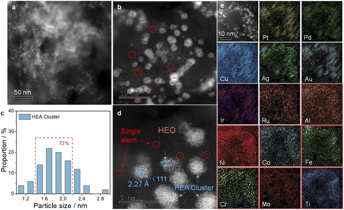 | ||
| Fig. 2 TEM ((a) low magnification and (b) high magnification) images and (c) size distributions of the HEA clusters on the HEO support. (d) HAADF-STEM and (e) STEM-EDS mapping of the sample. | ||
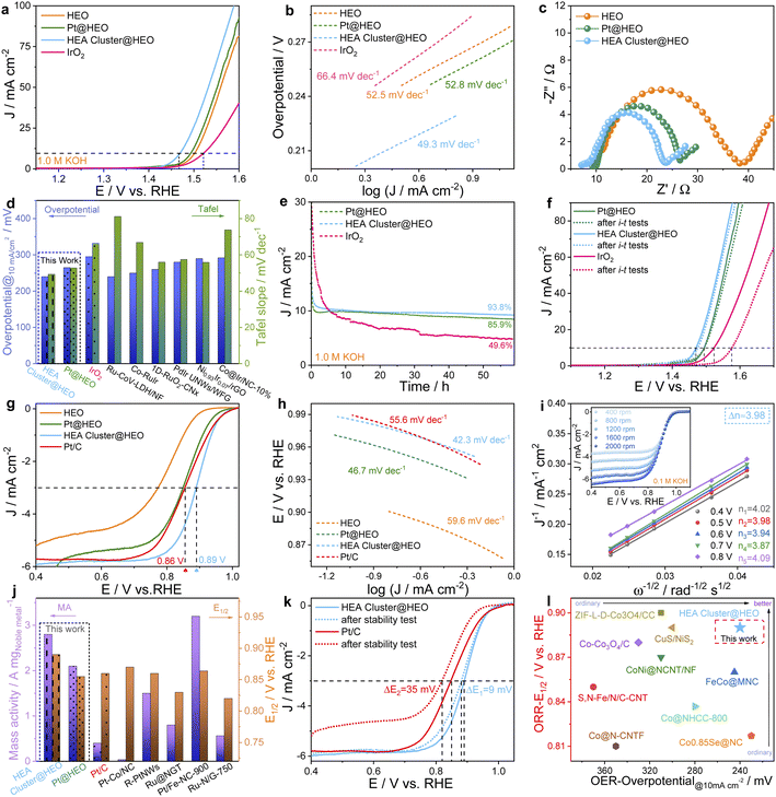
In order to make the HEO support highly OER active, we first optimized the composition of the HEO.9,42,43 In our previous research, we found that the AlNiCoFeMo-based HEO is highly active for the OER.23,26 We later found that in an eight-component HEO, the presence of both Cr and Fe would result in a synergistic catalytic effect for oxygen electrocatalysis.46 Thus, in this work, an AlNiCoFeCrMo-based HEO was designed and exhibited a high OER activity. Adding Ti to form seven-component AlNiCoFeCrMoTi can further enhance the OER activity, but further addition of V forming eight-component AlNiCoFeCrMoTiV, however, clearly decreased the activity. For more comparison, we also compared it with other oxides such as ternary AlNiFe, quaternary AlNiCoFe and quinary AlNiCoFeCr (Fig. S6†). The seven-component sample with the best OER activity was then adopted in this work.
The seven-component HEO shows even better OER catalytic performance than commercial IrO2 (Fig. 3a), by exhibiting a smaller overpotential at 10 mA cm−2. Interestingly, the OER performance was further improved by preparing the HEA cluster@HEO probably due to the increased active sites (such as Ru and Ir sites) and/or the electronic interaction at interfaces.43 Specifically, the HEA cluster@HEO requires only a small overpotential of 240 mV to provide a current density of 10 mA cm−2, while IrO2 needs an overpotential of ∼295 mV to reach the same current density. The performance is also outstanding when compared with most literature results (Table S1†). Meanwhile, the Tafel slope of the HEA cluster@HEO catalyst was 49.3 mV dec−1, which is smaller than that of IrO2 (66.4 mV dec−1) and other catalysts (HEO: 52.5 mV dec−1 and Pt@HEO: 52.8 mV dec−1) (Fig. 3b). It also has the smallest impedance resistance, indicating the fastest reaction kinetics (Fig. 3c). The detailed comparison of the overpotential, Tafel slope and other parameters with literature data is shown in Fig. 3d and Table S1.† The HEA cluster@HEO also shows a high catalytic durability with 93.8% current retention after a 50 h continuous OER test. Meanwhile, the retention of Pt@HEO and IrO2 was 85.9% and 49.6%, respectively (Fig. 3e). After the i–t test, we further performed the LSV test and found negligible performance decline for the HEA cluster@HEO (Fig. 3f).
For potential bifunctional electrocatalysis, their ORR activity was then investigated. We found that without noble metals, the HEO support alone exhibited the lowest ORR activity with an E1/2 of 0.78 V (Fig. 3g). The E1/2 increased to about 0.85 V when the HEO support is loaded with Pt clusters (i.e., Pt@HEO), indicating the key role of Pt clusters for the enhanced ORR performance. Interestingly, we found that the HEA cluster@HEO shows further enhanced ORR activity, with a highest E1/2 of ∼0.89 V, which is even better than that of Pt/C (E1/2: 0.86 V). Note that the loading atomic percentage of all 7 noble metals (PtPdAuAgCuIrRu) was designed to be the same as that of Pt in Pt@HEA to facilitate the comparison. Besides, HEA cluster@HEO shows the smallest Tafel slope of 42.3 mV dec−1, which is smaller than that of Pt/C (55.6 mV dec−1), HEO (59.6 mV dec−1) and Pt@HEO (46.7 mV dec−1), revealing the faster ORR kinetics (Fig. 3h).
The ORR performance of our HEA cluster@HEO catalyst is also higher than most literature reported results as shown in Table S2.† The ORR kinetics on HEA cluster@HEO was then examined by testing the ORR response at different rotational speeds (Fig. 3i). The obtained Koutecky–Levich plots show good linearity, suggesting first-order reaction kinetics toward the concentration of oxygen (Fig. 3i). The calculated n is about 3.98, revealing an efficient 4e− route. As shown in Fig. 3j, the HEA cluster@HEO catalyst exhibits a high noble metal mass activity (2.8 A mgnoble metal−1) at 0.9 V, which far exceeds that of commercial Pt/C (0.4 A mgPt−1) and other noble metal-containing catalysts (Fig. 3j and Table S2†).
The double-layer capacitance of HEO, Pt@HEO, and HEA cluster@HEO was then tested to reveal the corresponding electrochemical surface areas (Fig. S7†). Compared with that of HEO (22.86 mF cm−2), the Pt@HEO (25.61 mF cm−2) and HEA cluster@HEO (26.48 mF cm−2) samples show relatively larger double-layer capacitance, indicating an enlarged electrochemically active surface area (ECSA) due to the incorporation of noble metal-based clusters, which should contribute to better catalytic performance. We then tested the ORR stability of the HEA cluster@HEO and Pt/C by CV cycling. We can see that the change in half-wave potential was negligible for our HEA cluster@HEO, while the performance of Pt/C was significantly deteriorated (Fig. 3k). The outstanding durability of the HEA cluster@HEO may be attributed to both the high-entropy stabilization effect considering ΔG = ΔH − TΔS and the inherent strong interaction between the HEA clusters and HEO support.
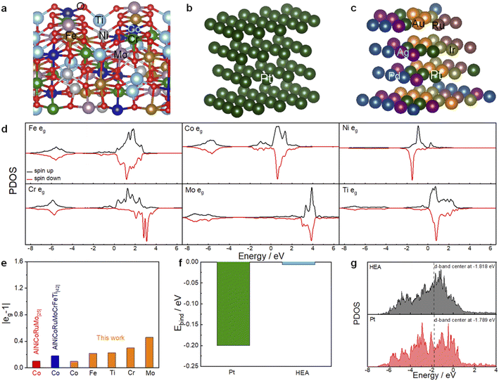
First-principles density functional theory (DFT) calculations have been performed to gain more insights into the inherent mechanism underlying the high entropy systems for the enhanced OER and ORR activity. The DFT computational details are presented in the ESI.† A computational model (FeCoNiMoCrTi)3O4 with a spinel structure (Fig. 4a) is constructed by partially substituting Co and Ni atoms with Fe, Mo, Cr and Ti atoms in NiCo2O4. Our previous studies have shown that multi-component spinel oxides exhibit much better OER activity than single-component and minor-component spinel oxides.47,48 Based on eg theory that the OER activity is the highest when the eg occupancy is close to unity,49 we then compare the eg occupancy of the active Co sites from the projected density of states (PDOSs, Fig. 4d), which is calculated through integration up to the Fermi level, as shown in Fig. 4e. The calculated eg occupancy of other elements of this HEO (1.22 (Fe), 1.30 (Cr), 1.46(Mo) and 0.77 (Ti)) is also shown. The eg occupancy of the Co site (1.10) is much closer to unity, suggesting a high OER activity by forming such HEO. This eg value is comparable with that of reported quinary AlNiCoRuMo-based HEO and smaller than that of the eight-component AlNiCoRuMoCrFeTi HEO. That is to say, without the addition of noble metal Ru, the Co site is also positively modified by forming such HEO. For the ORR, according to the Sabatier volcano plot of measured kinetic current density as a function of ΔEO, the catalytic activity reaches the maximum at a ΔEO of ≈0.2 eV weaker than that on Pt (111).50,51 As shown in Fig. 4f, the O absorption energy on HEA is much lower than that on Pt (111) and the difference from the optimal value is less than 0.01 eV. The mechanism of the enhanced ORR activity is also illustrated by the PDOS onto Pt d orbitals. As shown in Fig. 4g, the d-band center of Pt (−1.818 eV) in the HEA cluster is much lower than that in pure Pt (111) (−1.789 eV) due to the electronic interaction of different noble metals, which should result in a weaker absorption of O and enhanced ORR active sites. The corresponding Pt (111) and HEA model structures are shown in Fig. 4b and c, respectively. It should be mentioned that other active sites and the electronic interaction between the HEA clusters and the HEO support is not studied in this work due to the high complexity of the system.
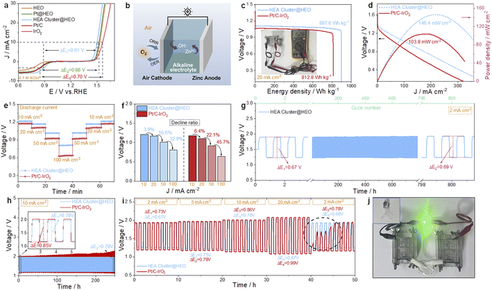
Fig. 5a shows that the voltage gap (ΔE) between the ORR half-wave potential (E1/2) and OER potential at 10 mA cm−2 (Ej=10) in 0.1 M KOH solution for the HEA cluster@HEO is only 0.61 V, which is smaller than that of Pt@HEO (0.66 V) and Pt/C–IrO2 (0.70 V) and even 20 mV smaller than the best reported ΔE of 0.63 V (CoNC@LDH).44 More comparison with literature reported bifunctional catalysts is shown in Fig. 3l and Table S3.† The excellent bifunctional activities of the designed high-entropy composite were then tested in rechargeable metal–air batteries (Fig. 5b). The open-circuit voltage (OCV) of the HEA cluster@HEO-based battery is 1.528 V (inset in Fig. 5c). The tested energy density is 897.6 W h kg−1, and the maximum power density is about 146.4 mW cm−2, which outperforms those of the Pt/C–IrO2-based battery (OCV: 1.462 V, Fig. S9,† energy density: 812.8 W h kg−1 and maximum power density: 103.8 mW cm−2, Fig. 5c and d). The performance is also clearly better than recently reported literature results as shown in Table S4.† When discharged at different current densities from 10 mA cm−2 to 100 mA cm−2, the HEA cluster@HEO battery exhibits higher discharge voltages than the Pt/C–IrO2 battery (Fig. 5e). From 10 to 100 mA cm−2, the discharge voltage dropped by 32.9% for the HEA cluster@HEO-based battery, which is much smaller than 45.7% for the Pt/C–IrO2-based battery (Fig. 5f), demonstrating the much better rate performance of the HEA cluster@HEO battery.
We then tested the cycling stability of the battery at both 2 and 10 mA cm−2. The HEA cluster@HEO-based battery exhibits smaller charge–discharge voltage differences and can be stably cycled at these different current densities (Fig. 5g and h). In comparison, the performance of the Pt/C–IrO2-based battery deteriorated significantly as the cycle number increased. We also tested the cycle stability under different current densities. As shown in Fig. 5i, under different currents (2, 5, 10 and 20 mA cm−2), the HEA cluster@HEO-based battery displays a clearly smaller charge/discharge voltage difference (0.67 V, 0.73 V, 0.78 V and 0.87 V, respectively) than the Pt/C–IrO2-based battery (0.73 V, 0.79 V, 0.86 V, and 0.99 V). Accelerated performance deterioration of the Pt/C–IrO2-based battery is also observed under identical testing conditions (Fig. 5i). Fig. 5j shows a photo of a 2.8 V LED light powered by two HEA cluster@HEO-based batteries in series.
After charge–discharge cycling at 10 mA cm−2 for more than 150 hours, the HEA cluster@HEO catalyst was again investigated by TEM and XPS. From the TEM analysis (Fig. S8a and b†), we can see that the noble metal-based HEA clusters are still evenly decorated on the HEO support after cycling without particle coarsening and all 14 elements are still uniformly distributed (Fig. S8c†). From the surface-sensitive XPS analysis, we found slight peak shifts for both noble (such as Au, Ir, Pd, etc.) and non-noble (such as Mo) elements. Probably due to the high potential applied during charging, these characteristic peaks all shifted slightly to higher binding energy states. This result indicates the surface microstructure change during the electrochemical oxidation/reduction process. However, based on the durability test, it is safe to conclude that the changed microstructure still delivers high performance for both the OER and the ORR.
3. Conclusion
In summary, through a facile two-step synthetic strategy, we realized the loading of ultra-small HEA clusters (PtPdAuAgCuIrRu) inherently on nanoporous spinel HEO nanowires (AlNiCoFeCrMoTi). Both the loading amount of HEA clusters and the compositions of HEA and HEO can be precisely tuned. The seven-component HEO is highly active for the OER, while the noble metal-based HEA clusters are responsible for the high ORR activity, resulting in a record-small ΔE of 0.61 V. It is worth mentioning that the loading of a small amount of noble metal also remarkably improves the OER performance, probably due to the strong metal/support synergistic electronic interaction and the increased active OER sites. Moreover, compared with Pt@HEO, the HEA cluster@HEO has greatly improved ORR activity with much less Pt. This work provides a wide designing space for multi-functional catalysts using high-entropy nanocomposite systems.The ORR kinetics of N-MG-800 was examined by RDE measurements at varied rotation speeds (Fig. 4b). The Koutecky–Levich plots in the inset of Fig. 4b show excellent linearity, indicating first-order reaction kinetics toward the concentration of dissolved oxygen in the electrolyte. The near parallelism of the fitting lines suggests a similar electron transfer number (n) for the ORR at different potentials. The value of n is calculated to be ≈3.94 from the slopes of Koutecky–Levich plots and demonstrates a near four-electron oxygen reduction process for N-MG-800, analogous to the Pt/C catalyst with n ≈ 4.0.
Author contributions
Z. J., X. Z. and Y. H. contributed equally to this work. H. J. Q. designed and supervised the project. Z. J. prepared the materials and did the electrochemical tests. X. Z. did the DFT calculation. Y. H. did the TEM characterization. H. J. Q., Z. J., X. L. and K. M. R wrote the paper. All authors revised the manuscript and discussed the results.Conflicts of interest
The authors declare no conflict of interest.Acknowledgements
The financial support is from the Shenzhen Fundamental Research Program (JCYJ20180507184623297), National Natural Science Foundation of China (No. 51871077, 52150610487 and 51850410501), and the Fund of Science and Technology on Reactor Fuel and Materials Laboratory (JCKYS2019201074).References
- H. M. Sun, Z. H. Yan, F. M. Liu, W. C. Xu, F. Y. Cheng and J. Chen, Adv. Mater., 2020, 32, 1806326 CrossRef CAS.
- L. Wang, Z. H. Zeng, W. P. Gao, T. Maxson, D. Raciti, M. Giroux, X. Q. Pan, C. Wang and J. Greeley, Science, 2019, 363, 870–874 CrossRef CAS PubMed.
- Y. Qiu, L. Xin, Y. W. Li, I. T. McCrum, F. M. Guo, T. Ma, Y. Ren, Q. Liu, L. Zhou, S. Gu, M. J. Janik and W. Z. Li, J. Am. Chem. Soc., 2018, 140, 16580–16588 CrossRef CAS PubMed.
- A. Rabis, P. Rodriguez and T. J. Schmidt, ACS Catal., 2012, 2, 864–890 CrossRef CAS.
- X. X. Wang, J. Sunarso, Q. Lu, Z. L. Zhou, J. Dai, D. Q. Guan, W. Zhou and Z. P. Shao, Adv. Energy Mater., 2020, 10, 1903271 CrossRef CAS.
- Q. Lu, J. Yu, X. H. Zou, K. M. Liao, P. Tan, W. Zhou, M. Ni and Z. P. Shao, Adv. Funct. Mater., 2019, 29, 1904481 CrossRef.
- F. L. Meng, K. H. Liu, Y. Zhang, M. M. Shi, X. B. Zhang, J. M. Yan and Q. Jiang, Small, 2018, 14, 1703843 CrossRef.
- J. Park, M. Park, G. Nam, J. S. Lee and J. Cho, Adv. Mater., 2015, 27, 1396–1401 CrossRef CAS PubMed.
- Y. X. Du, H. T. Sheng, D. Astruc and M. Z. Zhu, Chem. Rev., 2020, 120, 526–622 CrossRef CAS PubMed.
- B. Song, Y. Yang, M. Rabbani, T. T. Yang, K. He, X. B. Hu, Y. F. Yuan, P. Ghildiyal, V. P. Dravid, M. R. Zachariah, W. A. Saidi, Y. Z. Liu and R. Shahbazian-Yassar, ACS Nano, 2020, 14, 15131–15143 CrossRef PubMed.
- Y. F. Sun and S. Dai, Sci. Adv., 2021, 7, eabg1600 CrossRef CAS PubMed.
- J. C. Feng, D. Chen, P. V. Pikhitsa, Y. H. Jung, J. Yang and M. Choi, Matter, 2020, 3, 1646–1663 CrossRef.
- Z.-X. Cai, H. Goou, Y. Ito, T. Tokunaga, M. Miyauchi, H. Abe and T. Fujita, Chem. Sci., 2021, 12, 11306–11315 RSC.
- Y. Ma, Y. Ma, Q. Wang, S. Schweidler, M. Botros, T. Fu, H. Hahn, T. Brezesinski and B. Breitung, Energy Environ. Sci., 2021, 14, 2883–2905 RSC.
- T. Wang, H. Chen, Z. Z. Yang, J. Y. Liang and S. Dai, J. Am. Chem. Soc., 2020, 142, 4550–4554 CrossRef CAS.
- Z. J. Chen, T. Zhang, X. Y. Gao, Y. J. Huang, X. H. Qin, Y. F. Wang, K. Zhao, X. Peng, C. Zhang, L. Liu, M. H. Zeng and H. B. Yu, Adv. Mater., 2021, 33, 2101845 CrossRef CAS PubMed.
- S. Nellaiappan, N. K. Katiyar, R. Kumar, A. Parui, K. D. Malviya, K. G. Pradeep, A. K. Singh, S. Sharma, C. S. Tiwary and K. Biswas, ACS Catal., 2020, 10, 3658–3663 CrossRef CAS.
- Z. Jin, J. Lv, H. Jia, W. Liu, H. Li, Z. Chen, X. Lin, G. Xie, X. Liu, S. Sun and H. J. Qiu, Small, 2019, 15, e1904180 CrossRef.
- T. Loffler, H. Meyer, A. Savan, P. Wilde, A. G. Manjon, Y. T. Chen, E. Ventosa, C. Scheu, A. Ludwig and W. Schuhmann, Adv. Energy Mater., 2018, 8, 1802269 CrossRef.
- B. Gludovatz, A. Hohenwarter, D. Catoor, E. H. Chang, E. P. George and R. O. Ritchie, Science, 2014, 345, 1153–1158 CrossRef CAS PubMed.
- J. W. Yeh, S. K. Chen, S. J. Lin, J. Y. Gan, T. S. Chin, T. T. Shun, C. H. Tsau and S. Y. Chang, Adv. Energy Mater., 2004, 6, 299–303 CAS.
- G. L. Zhang, K. S. Ming, J. L. Kang, Q. Huang, Z. J. Zhang, X. R. Zheng and X. F. Bi, Electrochim. Acta, 2018, 279, 19–23 CrossRef CAS.
- H.-J. Qiu, G. Fang, J. Gao, Y. Wen, J. Lv, H. Li, G. Xie, X. Liu and S. Sun, ACS Mater. Lett., 2019, 1, 526–533 CrossRef CAS.
- D. S. Wu, K. Kusada, T. Yamamoto, T. Toriyama, S. Matsumura, S. Kawaguchi, Y. Kubota and H. Kitagawa, J. Am. Chem. Soc., 2020, 142, 13833–13838 CrossRef CAS PubMed.
- G. Feng, F. H. Ning, J. Song, H. F. Shang, K. Zhang, Z. P. Ding, P. Gao, W. S. Chu and D. G. Xia, J. Am. Chem. Soc., 2021, 143, 17117–17127 CrossRef CAS.
- Z. Y. Jin, J. Lyu, Y. L. Zhao, H. L. Li, X. Lin, G. Q. Xie, X. J. Liu, J. J. Kai and H. J. Qiu, ACS Mater. Lett., 2020, 2, 1698–1706 CrossRef CAS.
- Z. Y. Jin, J. Lyu, Y. L. Zhao, H. L. Li, Z. H. Chen, X. Lin, G. Q. Xie, X. J. Liu, J. J. Kai and H. J. Qiu, Chem. Mater., 2021, 33, 1771–1780 CrossRef CAS.
- A. Sarkar, Q. S. Wang, A. Schiele, M. R. Chellali, S. S. Bhattacharya, D. Wang, T. Brezesinski, H. Hahn, L. Velasco and B. Breitung, Adv. Mater., 2019, 31, 1806236 CrossRef.
- H. Chen, W. W. Lin, Z. H. Zhang, K. C. Jie, D. R. Mullins, X. H. Sang, S. Z. Yang, C. J. Jafta, C. A. Bridges, X. B. Hu, R. R. Unocic, J. Fu, P. F. Zhang and S. Dai, ACS Mater. Lett., 2019, 1, 83–88 CrossRef CAS.
- Y. F. Ye, Q. Wang, J. Lu, C. T. Liu and Y. Yang, Mater. Today, 2016, 19, 349–362 CrossRef CAS.
- S. Lee, J. Choi, M. Kim, J. Park, M. Park and J. Cho, Chem. Sci., 2022, 13, 6159–6180 RSC.
- F. Dong, M. J. Wu, Z. S. Chen, X. H. Liu, G. X. Zhang, J. L. Qiao and S. H. Sun, Nano-Micro Lett., 2022, 14, 36 CrossRef CAS PubMed.
- S. Zhang, M. Chen, X. Zhao, J. Cai, W. Yan, J. C. Yen, S. Chen, Y. Yu and J. Zhang, Electrochem. Energy Rev., 2021, 4, 336–381 CrossRef CAS.
- Y. G. Yao, Z. N. Huang, P. F. Xie, S. D. Lacey, R. J. Jacob, H. Xie, F. J. Chen, A. M. Nie, T. C. Pu, M. Rehwoldt, D. W. Yu, M. R. Zachariah, C. Wang, R. Shahbazian-Yassar, J. Li and L. B. Hu, Science, 2018, 359, 1489–1494 CrossRef CAS PubMed.
- H. D. Li, Y. Han, H. Zhao, W. J. Qi, D. Zhang, Y. D. Yu, W. W. Cai, S. X. Li, J. P. Lai, B. L. Huang and L. Wang, Nat. Commun., 2020, 11, 5437 CrossRef CAS PubMed.
- D. S. Wu, K. Kusada, T. Yamamoto, T. Toriyama, S. Matsumura, I. Gueye, O. Seo, J. Kim, S. Hiroi, O. Sakata, S. Kawaguchi, Y. Kubota and H. Kitagawa, Chem. Sci., 2020, 11, 12731–12736 RSC.
- T. Y. Li, Q. Dong, Z. N. Huang, L. P. Wu, Y. G. Yao, J. L. Gao, X. Z. Wang, H. C. Zhang, D. W. Wang, T. Li, R. Shahbazian-Yassar and L. B. Hu, Adv. Mater., 2022, 34, 2106436 CrossRef CAS PubMed.
- T. Y. Li, Y. G. Yao, B. H. Ko, Z. N. Huang, Q. Dong, J. L. Gao, W. Chen, J. G. Li, S. K. Li, X. Z. Wang, R. Shahbazian-Yassar, F. Jiao and L. B. Hu, Adv. Funct. Mater., 2021, 31, 2010561 CrossRef CAS.
- Y. Y. Liang, H. L. Wang, P. Diao, W. Chang, G. S. Hong, Y. G. Li, M. Gong, L. M. Xie, J. G. Zhou, J. Wang, T. Z. Regier, F. Wei and H. J. Dai, J. Am. Chem. Soc., 2012, 134, 15849–15857 CrossRef CAS PubMed.
- Y. M. Tan, C. F. Xu, G. X. Chen, X. L. Fang, N. F. Zheng and Q. J. Xie, Adv. Funct. Mater., 2012, 22, 4584–4591 CrossRef CAS.
- H. J. Huang, M. M. Yan, C. Z. Yang, H. Y. He, Q. G. Jiang, L. Yang, Z. Y. Lu, Z. Q. Sun, X. T. Xu, Y. Bando and Y. Yamauchi, Adv. Mater., 2019, 31, 1903415 CrossRef CAS PubMed.
- Z. Wu, B. Q. Jiang and Y. Liu, Appl. Catal., B, 2008, 79, 347–355 CrossRef CAS.
- H. L. Peng, F. F. Liu, X. J. Liu, S. J. Liao, C. H. You, X. L. Tian, H. X. Nan, F. Luo, H. Y. Song, Z. Y. Fu and P. Y. Huang, ACS Catal., 2014, 4, 3797–3805 CrossRef CAS.
- C.-X. Zhao, J.-N. Liu, J. Wang, D. Ren, J. Yu, X. Chen, B.-Q. Li and Q. Zhang, Adv. Mater., 2021, 33, 200806 Search PubMed.
- W. Jiao, P. Liu, H. J. Lin, W. Zhou, Z. Wang, T. Fujita, A. Hirata, H. W. Li and M. W. Chen, Chem. Mater., 2017, 29, 4478–4483 CrossRef CAS.
- Z. Y. Jin, J. Lyu, K. L. Hu, Z. H. Chen, G. Q. Xie, X. J. Liu, X. Lin and H. J. Qiu, Small, 2022, 18, 2107207 CrossRef CAS.
- G. Fang, J. J. Gao, J. Lv, H. L. Jia, H. L. Li, W. H. Liu, G. Q. Xie, Z. H. Chen, Y. Huang, Q. H. Yuan, X. J. Liu, X. Lin, S. H. Sun and H. J. Qiu, Appl. Catal., B, 2020, 268, 118431 CrossRef CAS.
- S. Y. Li, X. Y. Zhou, G. Fang, G. Q. Xie, X. J. Liu, X. Lin and H. J. Qiu, ACS Appl. Energy Mater., 2020, 3, 7710–7718 CrossRef CAS.
- X. Y. Wang, X. J. J. Gao, L. Qin, C. D. Wang, L. Song, Y. N. Zhou, G. Y. Zhu, W. Cao, S. C. Lin, L. Q. Zhou, K. Wang, H. G. Zhang, Z. Jin, P. Wang, X. F. Gao and H. Wei, Nat. Commun., 2019, 10, 704 CrossRef CAS PubMed.
- J. K. Norskov, J. Rossmeisl, A. Logadottir, L. Lindqvist, J. R. Kitchin, T. Bligaard and H. Jonsson, J. Phys. Chem. B, 2004, 108, 17886–17892 CrossRef CAS.
- Z. W. Seh, J. Kibsgaard, C. F. Dickens, I. B. Chorkendorff, J. K. Norskov and T. F. Jaramillo, Science, 2017, 355, 6321 CrossRef PubMed.
Footnote |
| † Electronic supplementary information (ESI) available. See https://doi.org/10.1039/d2sc04461g |
| This journal is © The Royal Society of Chemistry 2022 |

