 Open Access Article
Bismuth nanoparticles embedded in a carbon skeleton as an anode for high power density potassium-ion batteries†
Zhiqiang
Hao‡
 a,
Xiaoyan
Shi‡
a,
Wenqing
Zhu
a,
Xiaoyue
Zhang
a,
Zhuo
Yang
a,
Lin
Li
a,
Xiaoyan
Shi‡
a,
Wenqing
Zhu
a,
Xiaoyue
Zhang
a,
Zhuo
Yang
a,
Lin
Li
 *a,
Zhe
Hu
 *b,
Qing
Zhao
*c and
Shulei
Chou
 *a
*a
aInstitute for Carbon Neutralization, College of Chemistry and Materials Engineering, Wenzhou University, Wenzhou, Zhejiang 325035, China. E-mail: linli@wzu.edu.cn; chou@wzu.edu.cn
bCollege of Materials Science and Engineering, Shenzhen University, Shenzhen 518055, China. E-mail: huzhe@szu.edu.cn
cKey Laboratory of Advanced Energy Materials Chemistry (Ministry of Education), College of Chemistry, Nankai University, Tianjin 300071, China. E-mail: zhaoq@nankai.edu.cn
First published on 22nd August 2022
Abstract
Bismuth is a promising anode for potassium-ion batteries (PIBs) due to its suitable redox potential, large theoretical capacity, and superior electronic conductivity. Herein, we report a Bi@C (Bi nanoparticles uniformly embedded in a carbon skeleton) composite anode which delivers a superior rate performance of 244.3 mA h g−1 at 10.0 A g−1 and a reversible capacity of 255.6 mA h g−1 after 200 cycles in an optimized ether-based electrolyte. The outstanding electrochemical performance results from its robust structural design with fast reaction kinetics, which are confirmed by both experimental characterization studies and first-principles calculations. The reversible potassium storage mechanism of the Bi@C composite was also investigated by in situ X-ray diffraction. In addition, the full PIB cell assembled with a Bi@C composite anode and nickel-based Prussian blue analogue cathode exhibits high discharge voltage (3.18 V), remarkable power density (>10 kW kg−1), and an excellent capacity retention of 87.8% after 100 cycles. The results demonstrate that the PIBs with Bi anodes are promising candidates for power-type energy storage devices.
Introduction
Achieving carbon neutrality in the next few decades has gradually become the consensus among the world's countries.1 One of the effective strategies is to increase the share of renewable clean energy (such as wind, solar, and geothermal resources) in the electric energy structure.2–6 However, renewable clean energy is generally intermittent, so its development closely depends on large-scale energy storage/conversion systems.7–9 Recently, potassium-ion batteries (PIBs) have been considered as promising candidates for this purpose due to the high abundance of potassium resources and low redox potential of K+/K in an organic electrolyte (−2.93 V vs. the standard hydrogen electrode).10–12 In addition, the relatively weak interactions between K+ and organic solvents in comparison with other alkali ions (Li+ or Na+) are beneficial for PIBs to realize high rate performance.13,14 Unfortunately, the relatively large ionic radius of K+ (1.38 Å) inevitably results in sluggish K+ diffusion kinetics in electrodes, leading to poor rate performance of current PIBs.15,16 Simultaneously, large K+ also leads to a distinct volume expansion/shrink change during potassiation/depotassiation processes, especially for conversion or alloying type anode materials.17,18 Therefore, designing electrode materials with superior structural stability and fast electrochemical reaction kinetics is important to achieve PIBs with a high power density.Although various anodes (such as carbon materials, alloying materials, organic materials and metal chalcogenides) for PIBs have been reported, their applications in high power density PIBs still face challenges.19–28 Among these materials, metallic Bi shows huge potential for high power density PIBs due to the suitable redox potential, high electronic conductivity, and large theoretical capacity.29–32 However, Bi anodes generally suffer from large volume changes during the charge/discharge process and thus exhibit poor cycling stability.33,34 Rapid capacity fading was found for a pure Bi electrode at 5 A g−1 (only 90 mA h g−1 after 150 cycles).35 Various strategies, such as nanostructure engineering, alloying with other metals, hybridization with carbon materials, and electrolyte optimization, have been recently applied to improve the electrochemical performance of Bi anodes.35–41 For example, Li's group demonstrated that the cycling stability of commercial Bi was improved by replacing the conventional ester-based electrolyte with an ether-based electrolyte.17 Qiao et al. synthesized a carbon-coated double-shell nanostructured Bi box, demonstrating a reversible capacity of over 200 mA h g−1 after 200 cycles.20 In spite of this intriguing progress, it remains challenging to achieve both excellent cycling stability and rate performance by using one simple strategy. The application of Bi for high power density PIBs can be realized by both materials design and electrolyte optimization.42–45 Combining nanostructured Bi with carbon material coating and ether electrolyte design could be a promising strategy for both buffering the volume change and stabilizing the interphase of Bi anodes.
Herein, Bi nanoparticles uniformly embedded in a carbon skeleton (Bi@C) composites were prepared by a facile pyrolysis method with bismuth citrate as the precursor. The Bi@C anode displays a reversible capacity of 255.6 mA h g−1 even after 200 cycles and a high capacity of 244.3 mA h g−1 at 10.0 A g−1 coupled with the electrolyte of 1 M KPF6 in diethylene glycol dimethyl ether (DEGDME). The rapid reaction kinetics was further investigated by experimental characterization studies and first-principles calculations. In situ X-ray diffraction (XRD) reveals that Bi@C composites undergo a different potassium storage mechanism during the first and the following cycling process. Furthermore, full cells were constructed by matching with the nickel-based Prussian blue analogue (KNiHCF) cathode materials, which show an ultrahigh power density of over 10 kW kg−1.
Results and discussion
Material characterization studies
Bismuth citrate was used as the precursor to prepare Bi@C composites by simple one-step pyrolysis at 900 °C for 2 h under an Ar atmosphere. To determine whether the Bi@C composites were successfully synthesized, XRD was used to analyze the crystal structure of the sample. As shown in Fig. 1A, all the XRD peaks of the sample correspond to the hexagonal metal bismuth (JCPDS 85-1329), proving that the Bi@C composites were successfully synthesized. The invisible carbon peak from the XRD pattern indicates the low content of carbon in the Bi@C composites with an amorphous form. Raman spectroscopy was used to further investigate the form of carbon in Bi@C composites. As shown in Fig. S1,† the existence of both disordered carbon and graphitic carbon represented by the D band (1327 cm−1) and G band (1588 cm−1) could be detected. The intensity ratio between the D band and G band (ID/IG) is 1.06, which further confirms that carbon exists in an amorphous form.46,47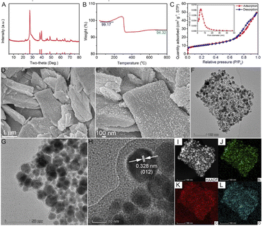 | ||
| Fig. 1 (A) XRD pattern, (B) TGA, (C) nitrogen adsorption–desorption isotherm and pore size distribution, (D, E) SEM images, (F–H) TEM images, and (I–L) EDS mapping images of Bi@C composites. | ||
Subsequently, the Bi content of the Bi@C sample was investigated by thermogravimetric analysis (TGA). As shown in Fig. 1B, the mass of the Bi@C composite material first slightly decreased to 99.17% due to the loss of absorbed water, then increased to a certain extent due to the oxidation of Bi, and finally decreased to 94.3% due to the oxidation of carbon. Therefore, the Bi content of Bi@C composites is about 85.3% (the calculation details can be seen in the Material characterization section in the ESI†). Through analysis of nitrogen adsorption and desorption, the specific surface area and the average pore diameter of Bi@C composites are determined to be about 33.96 m2 g−1 and 8.99 nm, respectively (Fig. 1C). The surface chemical states of the Bi@C composites were revealed by X-ray photoelectron spectroscopy (XPS, Fig. S2†). The full survey spectrum of Bi@C composites between 0 and 1000 eV clearly shows the three elements of Bi, C, and O (Fig. S2A†). In particular, the peaks at 164.41 and 159.10 eV in the Bi 4f spectrum (Fig. S2B†), 289.10 eV in the C 1s spectrum (Fig. S2C†), and 529.97 eV in the O 1s spectrum (Fig. S2D†) could be assigned to Bi–O, C–O and Bi–O–C bonds, respectively.48 These results indicated the existence of Bi–O–C bonds in Bi@C composites, which could be caused by the inevitable oxidation during the sample preparation process.30 The partial surface oxidation of the Bi@C composites is suggested to increase the interaction between Bi and the carbon matrix, which contributes to the structural stability of composites during charge/discharge.
The morphology and microstructure of the Bi@C composites were investigated by scanning electron microscopy (SEM) and transmission electron microscopy (TEM). The precursor bismuth citrate exhibits a sheet-like structure with a smooth surface (Fig. S3†), which is well maintained in Bi@C composites after the pyrolysis reaction (Fig. 1D and E). The TEM images demonstrate that Bi nanoparticles were uniformly embedded in the carbon skeleton (Fig. 1F–H), which is beneficial for improving structural stability and electronic conductivity. In addition, the nanoparticles exhibit an interplanar d-spacing of 0.328 nm, corresponding to the (012) lattice plane of Bi (Fig. 1H). As shown in Fig. 1I–L, the Bi, C, and O elements are uniformly distributed in the Bi@C composite, which also indicates that the Bi nanoparticles are evenly embedded in the carbon skeleton.
Electrochemical characterization studies
It is well known that the electrochemical performance of electrode materials is closely related to the type of electrolyte.49–52 Therefore, two types of electrolytes (1 M KPF6 in diethylene glycol dimethyl ether (DEGDME) and 0.8 M KPF6 in ethylene-carbonate (EC)/diethyl-carbonate (DEC)) are selected first to study the cycling performance and the selected charge/discharge curves of Bi@C composites (Fig. S4†). In an EC/DEC-based electrolyte, Bi@C composites exhibit significant decay in capacity. In comparison, no obvious capacity decay is observed in the DEGDME-based electrolyte after 20 cycles. Thus, the DEGDME-based electrolyte was selected to further investigate the electrochemical performance of the Bi@C composites.The electrochemical K+ storage behaviors of the Bi@C composite in the DEGDME-based electrolyte were first investigated by cyclic voltammetry (CV). As shown in Fig. 2A, the redox peaks of the Bi@C electrode are highly reversible, indicating the superior cycling stability of the Bi@C electrode. Subsequently, the potassium storage behaviors of Bi@C electrodes were investigated by a galvanostatic charge/discharge test. The typical charge/discharge curves of the Bi@C electrode at a current density of 500 mA g−1 are shown in Fig. 2B. The initial discharge and charge-specific capacities are 405.3 and 256.6 mA h g−1, respectively. The initial coulombic efficiency of the Bi@C composite electrode is 63.3%. The irreversible capacity in the first cycle could be mainly caused by the formation of a solid electrolyte interphase layer.53
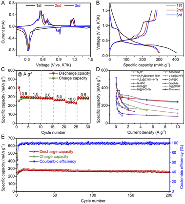 | ||
| Fig. 2 (A) CV curves, (B) typical charge/discharge curves, and (C) rate performance of Bi@C composite electrodes in 1 M KPF6 in DEGDME electrolyte. (D) Comparison of rate performance of the Bi@C composite electrode with other as-reported anodes for PIBs (K2TP,21 KTO/rGO,54 Sn4P3@carbon fiber,10 u-Sb@CNFs,55 V3S4a@C NS-HNTs,56 CoP@C,22 N-HPC,57 Graphite,11 BiSb@C,58 Bi@3DGF,59 and Bi@N-CNSs31). (E) Cycling performance. | ||
The rate performance of the Bi@C composite electrode was tested at different current densities ranging from 0.5 to 10 A g−1. As shown in Fig. 2C, the Bi@C composite electrode exhibits reversible capacities of 298.1, 293.8, 286.1, 265.2, and 244.3 mA h g−1 at current densities of 0.5, 1.0, 2.0, 5.0 and 10.0 A g−1, respectively. When the current density recovered to 0.5 A g−1, a high reversible capacity of 292.9 mA h g−1 can be retained, indicating the superior cycling stability of the Bi@C composite electrode. The corresponding charge/discharge curves of the Bi@C composite electrode at different current densities are shown in Fig. S5.† Among the as-reported anode materials for PIBs, the Bi@C composite shows competitive rate performance (Fig. 2D).10,11,21,22,31,54–59
The cycling performance of the Bi@C composite electrode at a current density of 5.0 A g−1 in the DEGDME-based electrolyte is shown in Fig. 2E. The Bi@C composite electrode shows superior cycling stability. A reversible discharge specific capacity of 255.6 mA h g−1 can be retained even after 200 cycles. Moreover, the shape of the charge/discharge curves is well maintained during cycling, proving the superior voltage stability (Fig. S6†). The outstanding cycling stability of the Bi@C composite could be attributed to the uniform embedding of Bi nanoparticles into the carbon skeleton, which contributes to alleviated volume expansion and inhibited electrode material pulverization. As shown in Fig. S7,† no obvious change in the sheet-like structure was found after 20 cycles. Meanwhile, no obvious resistance changes happen in electrochemical impedance spectroscopy upon 20 cycles (Fig. S8†). All these above results testify to the superior structural stability of the as-prepared Bi@C composite.
Kinetics of the Bi@C composite
To understand the reason for the superior rate performance of the Bi@C composite, the reaction kinetics were investigated by experimental characterization studies and first-principles calculations. The K+ diffusion coefficient of the Bi@C composite electrode was investigated by the galvanostatic intermittent titration technique (GITT). As shown in Fig. S9,† the voltage (E) is linearly related to . Therefore, the ion diffusion coefficient of the Bi@C composite electrode is calculated based on the following equation:44
 | (1) |
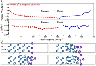 | ||
| Fig. 3 (A) GITT curves and the corresponding diffusion coefficients. (B) Snapshots of the AIMD simulation, Blue ball: Bi atoms; Purple ball: K atoms. | ||
Potassium storage mechanism
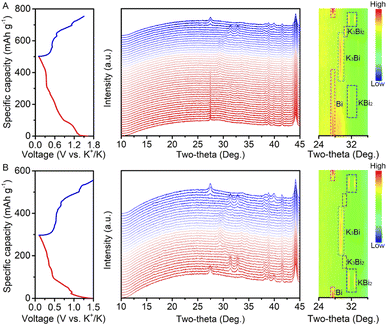
The potassium storage mechanism of the Bi@C composite was investigated by in situ XRD (Fig. 4). The initial charge/discharge curves and the corresponding XRD patterns are shown in Fig. 4A. During the discharge process, the characteristic peak of metallic Bi becomes weak gradually. The characteristic peak of KBi2 appears when discharged to ∼0.8 V. After discharging to ∼0.4 V, the diffraction peak of KBi2 disappears, and meanwhile, the characteristic peak of K3Bi appears. The intensity of K3Bi peaks increases gradually and reaches a maximum during the voltage window of 0.4–0.1 V. In the subsequent charging process, the peak intensity of K3Bi first attenuates gradually. After charging to ∼0.45 V, the peak of K3Bi disappears and emerges into a new peak, which corresponds to K3Bi2. Subsequently, the peak intensity of K3Bi2 strengthens and then weakens. The peak of KBi2 appears when the peaks of K3Bi2 fade away. Finally, the peaks of Bi appear with the declining peak intensity of KBi2, and then increase gradually until charging to 1.5 V.The in situ XRD pattern of the Bi@C composite in the second cycle is shown in Fig. 4B. Noticeably, the phase evolution of the Bi@C composite shows a slight difference during the discharge process compared with that in the initial cycle. The characteristic peak of K3Bi2 also appears. In the subsequent charging process, the reaction mechanism is similar to that in the first cycle. Based on the above results, we propose the following phase transition for the Bi@C composite in the DEGDME-based electrolyte:
| Bi → KBi2 → K3Bi (first discharge) | (2) |
| K3Bi → K3Bi2 → KBi2 → Bi (first charge) | (3) |
| Bi ↔ KBi2 ↔ K3Bi2 ↔ K3Bi (the following discharge/charge) | (4) |
Full cell
The potential for practical application of the Bi@C composite was further evaluated by fabricating full cells, which were assembled by using the nickel-based Prussian blue analogue (KNiHCF) cathode, 1 M KPF6 in DEGDME electrolyte, and the Bi@C composite anode (Fig. 5A). KNiHCF is a promising cathode material for high power density PIBs due to its wide channel for K+ diffusion.61 To assemble the full cell of the KNiHCF//Bi@C composite, both the cathode and anode were pre-activated in half cells for three cycles at a current density of 200 mA g−1 before the fabrication of a full cell. As shown in Fig. 5B, the KNiHCF//Bi@C full cell displays an initial discharge capacity of 57.2 mA h g−1 (based on the active mass of the cathode) and a high discharge voltage of 3.18 V at a current density of 100 mA g−1. The KNiHCF//Bi@C full cell demonstrates superior rate performance with reversible capacities of 57.2, 52.6, 49.0, 46.3, 42.2, and 33.3 mA h g−1 at current densities of 100, 200, 500, 1000, 2000, and 5000 mA g−1, respectively (Fig. 5C). The charge/discharge curves of the KNiHCF//Bi@C full cell at various current densities are displayed in Fig. S11.† The power density and energy density of the KNiHCF//Bi@C full cell are calculated based on the total active mass of the anode and cathode (Table S1†). As shown in Fig. 5D, the KNiHCF//Bi@C full cell exhibits a decent energy density of 68.6 W h kg−1 at an ultrahigh power density of >10 kW kg−1, surpassing those of most of the reported PIBs.17,61–66 In addition, the KNiHCF//Bi@C full cell also reveals superior cycling stability (a capacity retention of 87.8% after 100 cycles, Fig. 5E). The selected charge/discharge curves at a current density of 1000 mA g−1 are shown in Fig. S12.† These results indicate that the Bi@C composites are promising anode materials for high power density PIBs.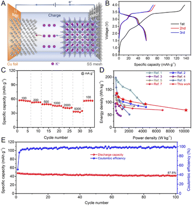 | ||
| Fig. 5 (A) Schematic illustration of the KNiHCF//Bi@C full cell during the charging process (SS: stainless-steel). (B) Typical charge/discharge curves of the KNiHCF//Bi@C full cell. (C) Rate performance of the KNiHCF//Bi@C full cell. (D) Comparison of the energy density and power density between the KNiHCF//Bi@C full cell and other reported potassium ion full cells (ref. 1: K1.92Fe[Fe(CN)6]0.94·0.5H2O//dipotassium terephthalate@carbon nanotube,62 ref. 2: K0.72Fe[Fe(CN)6]//Bi,17 ref. 3: PTCDA//soft carbon,63 ref. 4: K0.77MnO2·0.23H2O//hard-soft composite carbon,64 ref. 5: K0.51V2O5/graphite,65 ref. 6: KFe[Fe(CN)6]//Sb,66 and ref. 7: K1.84Fe[Fe(CN)6]0.88·0.49H2O//graphite61). (E) Cycling performance of the KNiHCF//Bi@C full cell. | ||
Conclusions
In summary, fast and stable K+ storage capability of Bi was achieved by the combination of nanostructure engineering, hybridization with carbon materials, and electrolyte optimization. In the optimized electrolyte, the Bi@C composite synthesized via a facile pyrolysis method shows superior cycling stability (a reversible capacity of 255.6 mA h g−1 after 200 cycles) and rate performance (244.3 mA h g−1 at 10.0 A g−1). The fast reaction kinetics was demonstrated by experimental characterization studies and first-principles calculations. The detailed phase transition process of the Bi@C composite during the charge/discharge process was revealed by in situ XRD investigation. In addition, the KNiHCF//Bi@C full cell shows a high discharge voltage of 3.18 V, an ultrahigh power density of >10 kW kg−1 and a capacity retention of 87.8% after 100 cycles. The facile synthesis and intriguing electrochemical properties will stimulate studies on high power density PIBs for power-type energy storage devices.Data availability
The data that support the findings of this study are available within the article and its ESI,† or from the corresponding author on reasonable request.Author contributions
Z. Hao and X. Shi contributed equally to this work. S. Chou and L. Li proposed the idea of this work and designed the experiments. Z. Hao and X. Shi carried out the preparation and electrochemical measurements. Q. Zhao, Z. Hao, and X. Shi performed characterization and data analysis. W. Zhu, X. Zhang, and Z. Yang organized the figures. Z. Hu performed the first-principles calculations. S. Chou, Z. Hu, Q. Zhao, L. Li, and Z. Hao wrote the manuscript. The manuscript was discussed and revised by all authors.Conflicts of interest
There are no conflicts to declare.Acknowledgements
This work was supported by the National Natural Science Foundation of China (52202286, 51971124 and 52171217) and Zhejiang Provincial Natural Science Foundation of China (LZ21E010001).Notes and references
- V. Scott and O. Geden, Nat. Energy, 2018, 3, 350–352 CrossRef CAS.
- A. Cherp, V. Vinichenko, J. Tosun, J. A. Gordon and J. Jewell, Nat. Energy, 2021, 6, 742–754 CrossRef.
- T. Song, C. Wang and C. S. Lee, Carbon Neutralization, 2021, 1, 68–92 CrossRef.
- S. Liu, L. Kang and S. C. Jun, Adv. Mater., 2021, 33, 2004689 CrossRef CAS PubMed.
- Y. Miao, X. Wang, H. Zhang, T. Zhang, N. Wei, X. Liu, Y. Chen, J. Chen and Y. Zhao, eScience, 2021, 1, 91–97 CrossRef.
- L. Chen, H. Wu, X. Ai, Y. Cao and Z. Chen, Battery Energy, 2022, 1, 20210006 CrossRef.
- H. Kim, J. C. Kim, M. Bianchini, D.-H. Seo, J. Rodriguez-Garcia and G. Ceder, Adv. Energy Mater., 2018, 8, 1702384 CrossRef.
- D.-T. Nguyen, A. Y. S. Eng, M.-F. Ng, V. Kumar, Z. Sofer, A. D. Handoko, G. S. Subramanian and Z. W. Seh, Cell Rep. Phys. Sci., 2020, 1, 100265 CrossRef CAS.
- Y. Guo, Y. Zhang and H. Lu, Battery Energy, 2022, 1, 20210014 CrossRef.
- W. Zhang, W. K. Pang, V. Sencadas and Z. Guo, Joule, 2018, 2, 1534–1547 CrossRef CAS.
- L. Li, L. Liu, Z. Hu, Y. Lu, Q. Liu, S. Jin, Q. Zhang, S. Zhao and S. L. Chou, Angew. Chem., Int. Ed., 2020, 59, 12917–12924 CrossRef CAS.
- J. Ge, L. Fan, A. M. Rao, J. Zhou and B. Lu, Nat. Sustain., 2022, 5, 225–234 CrossRef.
- Y. Y. Masaki Okoshi, S. Komaba, A. Yamada and H. Nakai, J. Electrochem. Soc., 2017, 164, A54–A60 CrossRef.
- M. Zhou, P. Bai, X. Ji, J. Yang, C. Wang and Y. Xu, Adv. Mater., 2021, 33, 2003741 CrossRef CAS.
- R. Zhang, J. Huang, W. Deng, J. Bao, Y. Pan, S. Huang and C.-F. Sun, Angew. Chem., Int. Ed., 2019, 58, 16474–16479 CrossRef CAS PubMed.
- Y. Liu, Z. Tai, J. Zhang, W. K. Pang, Q. Zhang, H. Feng, K. Konstantinov, Z. Guo and H. K. Liu, Nat. Commun., 2018, 9, 3645 CrossRef PubMed.
- K. Lei, C. Wang, L. Liu, Y. Luo, C. Mu, F. Li and J. Chen, Angew. Chem., Int. Ed., 2018, 57, 4687–4691 CrossRef CAS PubMed.
- D.-S. Bin, X.-J. Lin, Y.-G. Sun, Y.-S. Xu, K. Zhang, A.-M. Cao and L.-J. Wan, J. Am. Chem. Soc., 2018, 140, 7127–7134 CrossRef CAS PubMed.
- L. Fan, R. Ma, Q. Zhang, X. Jia and B. Lu, Angew. Chem., Int. Ed., 2019, 58, 10500–10505 CrossRef CAS PubMed.
- F. Xie, L. Zhang, B. Chen, D. Chao, Q. Gu, B. Johannessen, M. Jaroniec and S.-Z. Qiao, Matter, 2019, 1, 1681–1693 CrossRef.
- K. Lei, F. Li, C. Mu, J. Wang, Q. Zhao, C. Chen and J. Chen, Energy Environ. Sci., 2017, 10, 552–557 RSC.
- Q. Liu, Z. Hu, Y. Liang, L. Li, C. Zou, H. Jin, S. Wang, H. Lu, Q. Gu, S. Chou, Y. Liu and S.-X. Dou, Angew. Chem., Int. Ed., 2020, 59, 5159–5164 CrossRef CAS PubMed.
- L. Li, Z. Hu, Y. Lu, S. Zhao, Q. Zhang, Q. Liu, Z. Yan and S.-L. Chou, J. Energy Chem., 2021, 63, 246–252 CrossRef.
- L. Yang, W. Hong, Y. Tian, G. Zou, H. Hou, W. Sun and X. Ji, Chem. Eng. J., 2020, 385, 123838 CrossRef CAS.
- J. Li, N. Zhuang, J. Xie, X. Li, W. Zhuo, H. Wang, J. B. Na, X. Li, Y. Yamauchi and W. Mai, Adv. Energy Mater., 2020, 10, 1903455 CrossRef CAS.
- J. Zhou, Y. Liu, S. Zhang, T. Zhou and Z. Guo, InfoMat, 2020, 2, 437–465 CrossRef CAS.
- H. Lei, J. Li, X. Zhang, L. Ma, Z. Ji, Z. Wang, L. Pan, S. Tan and W. Mai, InfoMat, 2022, 4, e12272 CrossRef CAS.
- P. Li, H. Kim, K.-H. Kim, J. Kim, H.-G. Jung and Y.-K. Sun, Chem. Sci., 2021, 12, 7623–7655 RSC.
- H. Yuan, Y. Jin, X. Chen, J. Lan, Y. Yu and X. Yang, ACS Sustain. Chem. Eng., 2019, 7, 6033–6042 CrossRef CAS.
- P. Xiong, P. Bai, A. Li, B. Li, M. Cheng, Y. Chen, S. Huang, Q. Jiang, X. H. Bu and Y. Xu, Adv. Mater., 2019, 31, 1904771 CrossRef CAS.
- Z. Sun, Y. Liu, W. Ye, J. Zhang, Y. Wang, Y. Lin, L. Hou, M. S. Wang and C. Yuan, Angew. Chem., Int. Ed., 2021, 60, 7180–7187 CrossRef CAS PubMed.
- Y. Zhao, X. Ren, Z. Xing, D. Zhu, W. Tian, C. Guan, Y. Yang, W. Qin, J. Wang, L. Zhang, Y. Huang, W. Wen, X. Li and R. Tai, Small, 2020, 16, 1905789 CrossRef CAS PubMed.
- V. Gabaudan, R. Berthelot, L. Stievano and L. Monconduit, J. Phys. Chem. C, 2018, 122, 18266–18273 CrossRef CAS.
- Q. Zhang, J. Mao, W. K. Pang, T. Zheng, V. Sencadas, Y. Chen, Y. Liu and Z. Guo, Adv. Energy Mater., 2018, 8, 1703288 CrossRef.
- X. Shi, J. Zhang, Q. Yao, R. Wang, H. Wu, Y. Zhao and L. Guan, J. Mater. Chem. A, 2020, 8, 8002–8009 RSC.
- J. Huang, X. Lin, H. Tan and B. Zhang, Adv. Energy Mater., 2018, 8, 1703496 CrossRef.
- C. Huang, A. Xu, G. Li, H. Sun, S. Wu, Z. Xu and Y. Yan, Small, 2021, 17, 2100685 CrossRef CAS PubMed.
- L. Zhou, Z. Cao, W. Wahyudi, J. Zhang, J.-Y. Hwang, Y. Cheng, L. Wang, L. Cavallo, T. Anthopoulos, Y.-K. Sun, H. N. Alshareef and J. Ming, ACS Energy Lett., 2020, 5, 766–776 CrossRef CAS.
- T. Jiao, S. Wu, J. Cheng, D. Chen, D. Shen, H. Wang, Z. Tong, H. Li, B. Liu, J.-J. Kai, C.-S. Lee and W. Zhang, J. Mater. Chem. A, 2020, 8, 8440–8446 RSC.
- S. Ye, L. Wang, F. Liu, P. Shi and Y. Yu, eScience, 2021, 1, 75–82 CrossRef.
- J. Mao, C. Wang, Y. Lyu, R. Zhang, Y. Wang, S. Liu, Z. Wang, S. Zhang and Z. Guo, J. Mater. Chem. A, 2022 10.1039/D2TA02223K.
- L. Li, S. Zhao, Z. Hu, S.-L. Chou and J. Chen, Chem. Sci., 2021, 12, 2345–2356 RSC.
- R. Zhang, J. Bao, Y. Wang and C.-F. Sun, Chem. Sci., 2018, 9, 6193–6198 RSC.
- H. Yang, R. Xu, Y. Yao, S. Ye, X. Zhou and Y. Yu, Adv. Funct. Mater., 2019, 29, 1809195 CrossRef.
- X. Liu, X. Yu, Y. Tong, Y. Sun, W. Mai, L. Niu and H. Li, Chem. Eng. J., 2022, 446, 137329 CrossRef CAS.
- S. Qi, X. Xie, X. Peng, D. H. L. Ng, M. Wu, Q. Liu, J. Yang and J. Ma, Phys. Status Solidi RRL, 2019, 13, 1900209 CrossRef CAS.
- F. Chen, Y. Di, Q. Su, D. Xu, Y. Zhang, S. Zhou, S. Liang, X. Cao and A. Pan, Carbon Energy, 2022, 1–12 Search PubMed.
- Z. Liu, S. Zhao, G. Li, C. Chen, X. Xie, Z. Wu and N. Zhang, Inorg. Chem. Front., 2022, 9, 3165–3175 RSC.
- Y. Liu, C. Gao, L. Dai, Q. Deng, L. Wang, J. Luo, S. Liu and N. Hu, Small, 2020, 16, 2004096 CrossRef CAS.
- J. Li, Y. Hu, H. Xie, J. Peng, L. Fan, J. Zhou and B. Lu, Angew. Chem., Int. Ed., 2022, 61, e202208291 CAS.
- L. Fan, Y. Hu, A. M. Rao, J. Zhou, Z. Hou, C. Wang and B. Lu, Small Methods, 2021, 5, 2101131 CrossRef CAS.
- Y. Hu, L. Fan, A. M. Rao, W. Yu, C. Zhuoma, Y. Feng, Z. Qin, J. Zhou and B. Lu, Natl. Sci. Rev., 2022, 9, nwac134 CrossRef.
- X.-D. He, J.-Y. Liao, S. Wang, J.-R. Wang, Z.-H. Liu, X. Ding, Q. Hu, Z.-Y. Wen and C.-H. Chen, J. Mater. Chem. A, 2019, 7, 27041–27047 RSC.
- C. Zeng, F. Xie, X. Yang, M. Jaroniec, L. Zhang and S.-Z. Qiao, Angew. Chem., Int. Ed., 2018, 57, 8540–8544 CrossRef CAS.
- X. Ge, S. Liu, M. Qiao, Y. Du, Y. Li, J. Bao and X. Zhou, Angew. Chem., Int. Ed., 2019, 58, 14578–14583 CrossRef CAS.
- Y. Liu, Z. Sun, X. Sun, Y. Lin, K. Tan, J. Sun, L. Liang, L. Hou and C. Yuan, Angew. Chem., Int. Ed., 2020, 59, 2473–2482 CrossRef CAS PubMed.
- X. Zhou, L. Chen, W. Zhang, J. Wang, Z. Liu, S. Zeng, R. Xu, Y. Wu, S. Ye, Y. Feng, X. Cheng, Z. Peng, X. Li and Y. Yu, Nano Lett., 2019, 19, 4965–4973 CrossRef CAS PubMed.
- P. Xiong, J. Wu, M. Zhou and Y. Xu, ACS Nano, 2020, 14, 1018–1026 CrossRef CAS PubMed.
- X. Cheng, D. Li, Y. Wu, R. Xu and Y. Yu, J. Mater. Chem. A, 2019, 7, 4913–4921 RSC.
- R. Zhang, J. Bao, Y. Pan and C.-F. Sun, Chem. Sci., 2019, 10, 2604–2612 RSC.
- L. Li, Z. Hu, Y. Lu, C. Wang, Q. Zhang, S. Zhao, J. Peng, K. Zhang, S. L. Chou and J. Chen, Angew. Chem., Int. Ed., 2021, 60, 13050–13056 CrossRef CAS PubMed.
- J. Liao, Q. Hu, Y. Yu, H. Wang, Z. Tang, Z. Wen and C. Chen, J. Mater. Chem. A, 2017, 5, 19017–19024 RSC.
- L. Fan, R. Ma, J. Wang, H. Yang and B. Lu, Adv. Mater., 2018, 30, 1805486 CrossRef.
- B. Lin, X. Zhu, L. Fang, X. Liu, S. Li, T. Zhai, L. Xue, Q. Guo, J. Xu and H. Xia, Adv. Mater., 2019, 31, 1900060 CrossRef PubMed.
- Y.-H. Zhu, Q. Zhang, X. Yang, E.-Y. Zhao, T. Sun, X.-B. Zhang, S. Wang, X.-Q. Yu, J.-M. Yan and Q. Jiang, Chem, 2019, 5, 168–179 CAS.
- X.-D. He, Z.-H. Liu, J.-Y. Liao, X. Ding, Q. Hu, L.-N. Xiao, S. Wang and C.-H. Chen, J. Mater. Chem. A, 2019, 7, 9629–9637 RSC.
Footnotes |
| † Electronic supplementary information (ESI) available. See https://doi.org/10.1039/d2sc04217g |
| ‡ These authors contributed equally to this work. |
| This journal is © The Royal Society of Chemistry 2022 |

