
 Open Access Article
 This Open Access Article is licensed under a Creative Commons Attribution-Non Commercial 3.0 Unported Licence
Designing inorganically functionalized magic-size II–VI clusters and unraveling their surface states†
Junjun
Ge
,
Jing
Liang
,
Xufeng
Chen
,
Yalei
Deng
,
Pengwei
Xiao
,
Jun-Jie
Zhu
 and
Yuanyuan
Wang
*
and
Yuanyuan
Wang
*
State Key Laboratory of Coordination Chemistry, School of Chemistry and Chemical Engineering, Nanjing University, Nanjing 210093, China. E-mail: wangyy@nju.edu.cn
First published on 20th September 2022
Abstract
Surface engineering is a critical step in the functionalization of nanomaterials to improve their optical and electrochemical properties. However, this process remains a challenge in II–VI magic-size clusters (MSCs) due to their high sensitivity to the environment. Herein, we developed a general surface modification strategy to design all-inorganic MSCs by using certain metal salts (cation = Zn2+, In3+; Anion = Cl−, NO3−, OTf−) and stabilized (CdS)34, (CdSe)34 and (ZnSe)34 MSCs in polar solvents. We further investigated the surface states of II–VI MSCs using electrochemiluminescence (ECL). The mechanism study revealed that the ECL emission was attributed to  . Two ECL emissions at 556 nm and 530 nm demonstrated two surface passivation modes on (CdS)34 MSCs, which can be tuned by the surface ligands. The achievement of surface engineering opens a new design space for functional MSC compounds.
Introduction
Magic-size clusters (MSCs), referring to the discrete growth of ultrasmall and monodisperse nanomaterials with countable atoms, bridge the gap between molecular complexes and nanocrystals (NCs).1–5 The discovery and isolation of semiconductor MSCs improved our understanding of their optical and catalytic properties at the molecular level and provided building blocks for the assembly of new superstructures with various dimensions.6–11 Recently, the single-crystal structure of the Se–Cd14Se12 core-cage arrangement of Cd14Se13 MSCs was reported, which is the first example of nearly stoichiometric CdSe clusters and demystified the MSC structure.12 However, compared with NCs, the limitations of MSCs in precisely tuning properties greatly hinder the development of their practical applications.13 Therefore, it is extremely important to find suitable methods to rationally design MSCs.Postsynthetic surface treatment is an efficient route to fine-tuning the properties of nanomaterials.14–16 Ligand exchange has been established as an effective method for surface engineering and is widely used in the surface treatment of NCs.17–19 The treated NCs show higher electron mobility and improved electrochemical and catalytic performance.20–24 However, the strategy is not applicable to MSCs because of their high sensitivity to the environment.4,9,25 In addition, the lack of suitable techniques for the studies of MSC surface chemistry further hindered an in-depth understanding of their properties at the molecular level.2
In this work, we developed a general surface engineering strategy to obtain colloidal stable all-inorganic MSCs in polar solvents and demonstrated that electrochemiluminescence (ECL) is an efficient technique to monitor the surface properties of semiconductor MSCs. Specifically, all-inorganic (CdS)34, (CdSe)34 and (ZnSe)34 MSCs were prepared by exchanging L-type ligands with certain metal salt ligands (cation = Zn2+, In3+; Anion = Cl−, NO3−, OTf−). Optical measurements, Raman spectroscopy, inductively coupled plasma optical emission spectrometry (ICP-OES), and laser-desorption-ionization mass spectrometry (LDI-MS) were used to demonstrate the integrality of MSCs during surface treatment. Importantly, we used ECL to characterize the surface states of semiconductor MSCs. The mechanism study revealed that the ECL emissions of (CdS)34 MSCs were attributed to  . We further demonstrated that (CdS)34 MSCs had two types of surface states, Cd passivation and S passivation, which can be tuned by inorganic ligands to achieve improved ECL performance. We believe that the success of surface chemistry using metal salts and the development of ECL for the study of surface states can greatly expand the potential applications of all-inorganic MSCs.
Results and discussion
The MSCs studied in this work were synthesized following previously reported procedures.26 We used CdS MSCs as a model system, which were prepared by reacting the Cd precursor (CdCl2 dissolved in butylamine (BTA)) and the S precursor (S dissolved in BTA). The UV-vis absorption spectrum (Fig. S1a, black line†) exhibited two sharp absorbances at 365 and 335 nm, closely matching the spectrum of (CdS)34.27 ICP-OES analysis showed a 1![[thin space (1/6-em)]](https://www.rsc.org/images/entities/char_2009.gif) :1 ratio of Cd:S in these MSCs, which proved to be stoichiometry (CdS)x (Table S1†). The x was determined to be 34 by LDI-MS as illustrated in Fig. 3c.
:1 ratio of Cd:S in these MSCs, which proved to be stoichiometry (CdS)x (Table S1†). The x was determined to be 34 by LDI-MS as illustrated in Fig. 3c.
Preparation of colloidal stable all-inorganic (CdS)34 MSCs in polar solvents
Ligand exchange is a coupled equilibrium process in which the binding energy of the original surface ligands is compensated by adducts between the released original ligands and the foreign ligands.28 Since the primary amine dynamically interacts with MSCs, the replacement of organics can be easily achieved through a direct phase transfer procedure, as illustrated in Fig. 1a. Specifically, we combined a solution of as-synthesized (CdS)34-BTA MSCs in hexane (Hex) with solutions of inorganic ligands (ZnCl2, Zn(NO3)2 or Zn(OTf)2) in N,N-dimethylformamide (DMF). The two-phase mixture was vigorously stirred for a short time, after which a complete phase transfer was observed, leaving the hexane layer colorless (Fig. 1b). We referred to the treated MSCs as (CdS)34–ZnCl2, (CdS)34–Zn(NO3)2 and (CdS)34–Zn(OTf)2. It should be emphasized that the given names do not represent the actual coordination situation. | ||
| Fig. 1 (a) Schematic illustration of the ligand exchange procedure in (CdS)34 MSCs. (b) (CdS)34 MSCs undergo phase transfer from hexane to DMF upon exchange of the organic ligands with ZnCl2. (c) Absorption, PL and PLE spectra of (CdS)34–ZnCl2 MSCs. (d) IR spectra (e) TGA and (f) Raman spectra of as-synthesized (CdS)34-BTA (black) and (CdS)34–ZnCl2 (red) MSCs. | ||
Fig. 1c shows the absorption spectrum of (CdS)34–ZnCl2 MSCs in DMF. Compared with (CdS)34-BTA MSCs, a blue-shift of 9 nm was observed, which was due to the solvation effect and the reduction of the effective radius caused by the removal of organic ligands.29 In the photoluminescence (PL) spectrum, the sharp peak at 378 nm and the broad peak at 482 nm corresponded to the band gap and surface trap state of the MSCs, respectively. The photoluminescence excitation (PLE) spectrum exhibited nearly the same transitions as the absorption spectrum, confirming that the bandgap structure of the (CdS)34 MSCs was unchanged after ligand exchange. The red-shift between the PLE and absorption spectra was attributed to different fine structure states contributing to each signal, which was also observed in (CdSe)13 MSCs.30
The ICP-OES results (Table S1†) showed that the ratio of Cd:S in the treated (CdS)34–ZnCl2 MSCs remained 1:1, proving that their composition was consistent with that of the original (CdS)34-BTA MSCs. In addition, 22% Zn indicated the existence of ZnCl2 ligands on treated (CdS)34 MSCs. Fourier transform infrared spectroscopy (FTIR) measurements were used to monitor the completeness of ligand exchange (Fig. 1d). The bands in the regions of 3000–2800 cm−1/1500–1300 cm−1 and 3300–3000 cm−1/1600–1500 cm−1 corresponding to C–H and N–H stretching in the organic ligands almost completely disappeared, which confirmed the efficacy of ZnCl2 in the removal of the original organic ligands. Fig. 1e shows the TGA studies of (CdS)34 MSCs before and after ZnCl2 treatment, which were collected by heating the samples from room temperature to 450 °C. The total weight loss of (CdS)34–ZnCl2 MSCs was 10%, much lower than that of the untreated sample (18%), providing further evidence for the exchange of organic ligands by inorganic ZnCl2. It is worth mentioning that (CdS)34–ZnCl2 MSCs lost 6% weight in the range of 200–300 °C, which was attributed to the weight loss of ZnCl2 (Fig. S1b†), and a small amount of solvent DMF acted as a ligand for (CdS)34, corresponding to weight loss in the range of 140–200 °C.18
The role of ZnCl2 in the surface treatment was studied by Raman spectroscopy. In Fig. 1f, two characteristic features located at approximately 296 (1LO) and 591 cm−1 (2LO) were observed in both organic ligand-protected and all-inorganic (CdS)34 MSCs, while the peaks of LO phonons of ZnS did not appear.31 The results indicated that ZnCl2 served as a ligand to coordinate with the surface atoms of (CdS)34 MSCs rather than precursors to form the shell structure. We also studied the stability of MSCs after surface treatment. Fig. S2† shows that the solution of (CdS)34–ZnCl2 MSCs maintained good dispersion in DMF, N-methylformamide (NMF) and acetone after 60 hours.
In addition to ZnCl2, Zn(NO3)2 and Zn(OTf)2 could also function as metal salt ligands to modify (CdS)34 MSCs (Fig. 2a). Similar to ZnCl2, a 9 nm blue-shift in the absorption spectrum was also observed in Zn(NO3)2- and Zn(OTf)2-treated MSCs (Fig. 2b and c). The PLE spectra and ICP-OES results proved the integrity of (CdS)34 before and after surface treatment (Table S1†). The FT-IR spectra (Fig. 2d) confirmed the complete replacement of the organic ligands in the (CdS)34–Zn(NO3)2 and (CdS)34–Zn(OTf)2 MSCs. Similar to (CdS)34–ZnCl2, the Raman spectra of (CdS)34–Zn(NO3)2 and (CdS)34–Zn(OTf)2 MSCs showed that the metal salts were ligated to the surface of (CdS)34 MSCs (Fig. 2e). Surprisingly, the PL spectrum of (CdS)34–Zn(OTf)2 was significantly different from that of (CdS)34–ZnCl2 or (CdS)34–Zn(NO3)2 MSCs. Specifically, the ratio of band gap PL emission intensity to trap PL emission intensity increased significantly, indicating the reduction of the surface trap in (CdS)34–Zn(OTf)2 MSCs. We attributed this to the different passivation motifs of (CdS)34–Zn(OTf)2 MSCs which will be discussed in detail below.
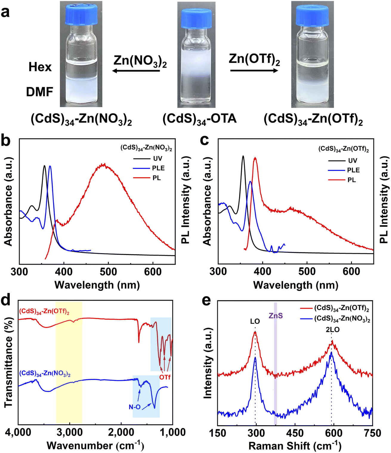 | ||
| Fig. 2 (a) (CdS)34 MSCs undergo phase transfer from hexane to DMF upon exchange of the organic ligands with Zn(NO3)2 and Zn(OTf)2. (b) Absorption, PL and PLE spectra of (CdS)34–Zn(NO3)2 (c) Absorption, PL and PLE spectra of (CdS)34–Zn(OTf)2, (d) IR spectra and (e) Raman spectra of (CdS)34–Zn(NO3)2 and (CdS)34–Zn(OTf)2 MSCs. | ||
In addition to inorganic metal salts, organometallic salts can also serve as ligands to functionalize MSCs, forming pseudo-all-inorganic MSCs. For example, a complete phase transfer was observed for (CdS)34 MSCs from hexane to DMF in the presence of Zn(OAc)2 (Fig. S4a†). ICP-OES (Table S1†) demonstrated the invariance of their composition, and the IR and TGA spectra proved the existence of Zn(OAc)2 (Fig. S3†). The successful surface engineering of (CdS)34 MSCs and their stabilization in polar solvents with metal salt ligands open a new surface design space for functional MSC compounds.
Reversible exchange of inorganic ligands to L-type ligands
Precisely controllable ligand exchange is an important step in designing functional materials.18 In addition, reversible ligand exchange helps us understand interactions between MSCs and ligands.32 However, most surface modification approaches are typically irreversible, which inspired us to study the fully reversible phase transfer and programmed surface functionalization of MSCs.18Exposure of (CdS)34–ZnCl2, (CdS)34–Zn(OTf)2 or (CdS)34–Zn(OAc)2 MSCs to L-type ligands, oleylamine (OLA), resulted in an immediate reverse exchange of MSCs from the DMF layer to the hexane layer. We named them as (CdS)34–ZnCl2-OLA, (CdS)34–Zn(OTf)2-OLA or (CdS)34–Zn(OAc)2-OLA MSCs. The absorption spectra (Fig. 3a) and the LDI-MS spectra (Fig. 3c) were used to confirm the integrity of MSCs. Similar to (CdS)34-BTA MSCs, (CdS)34–ZnCl2-OLA MSCs contained prominent peaks at m/z 4913.62, as well as a sequence of fragment ions corresponding to (CdS)13 at m/z 1877.35. ICP-OES data indicated that both all-inorganic and organic ligand-capped (CdS)34 MSCs had a stoichiometric ratio of 1:1 of Cd:S (Table S1†). The significantly increased C–H and N–H stretching intensities in the FTIR spectra confirmed the occurrence of the secondary ligand-exchange reaction (Fig. 3b). The dramatical decrease in Zn was further confirmed by the success of the replacement of ZnCl2 and Zn(OAc)2 by L-type ligands (Table S1†). Interestingly, we noticed that the content of Zn was not changed after OLA recapped on (CdS)34–Zn(OTf)2 MSCs, which may be due to the fact that Zn(OTf)2 interacted with MSCs in a different way rather than ZnCl2 and Zn(NO3)2 did (this will be discussed in the following section).
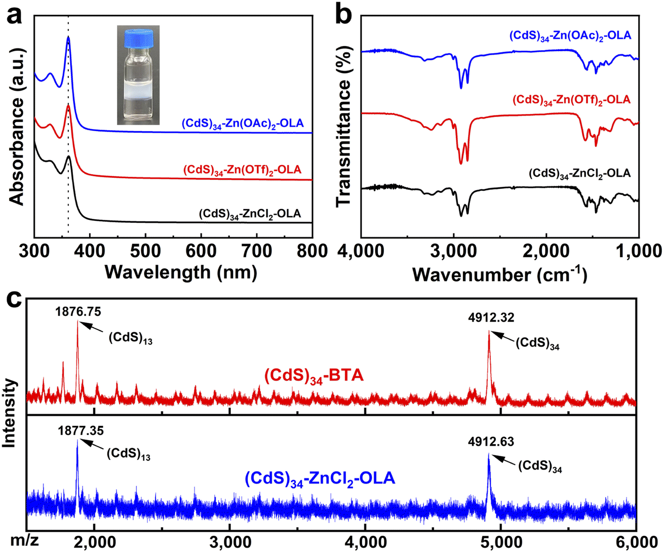 | ||
| Fig. 3 Surface functionalization of metal salt-modified MSCs by a secondary ligand-exchange process: (a) absorption spectra and (b) IR spectra of OLA treated (CdS)34–ZnCl2 (black), (CdS)34–Zn(OTf)2 (red) and (CdS)34–Zn(OAc)2 (blue) MSCs. The inset of figure a shows a photograph of OLA-modified (CdS)34–Zn(OAc)2 MSCs in hexane. (c) LDI-MS of as-synthesized (CdS)34-BTA and OLA treated (CdS)34–ZnCl2-OLA MSCs. | ||
Metal salts as ligands for other MSCs
To explore the generality of metal salt treatment, we further studied the surface modification of (CdSe)34 and (ZnSe)34 MSCs, which are also important components of II–VI semiconductor MSCs.The combination of organic capped (CdSe)34 MSCs in hexene and ZnCl2 or Zn(OAc)2 in DMF at room temperature resulted in a phase transfer from nonpolar solvent to polar solvent (Fig. 4a and b), which was accompanied by the slight spectral blue-shift shown in Fig. S4a.† The Cd:Se ratio in the as-prepared and treated (CdSe)34 MSCs was consistent with the stoichiometric MSCs, demonstrating that their composition remained unchanged during the ligand exchange process. The replacement of the initial L-type ligands by metal salt ligands was supported by IR spectra (Fig. 4d) and TGA studies (Fig. S4c†). In addition, 14–31% Zn was contained in the metal salt capped MSCs, which indicated the modification of inorganic ligands (Table S2†). Raman spectra provided strong evidence that ZnCl2 and Zn(OAc)2 coordinated with surface atoms as ligands (Fig. S4b†). Exposure of any of the metal salt-ligated (CdSe)34 MSCs to OLA resulted in immediate back exchange to L-type ligation with a return shift of the MSC absorption features to the original positions. LDI-MS proved that (CdSe)34 MSCs remained unchanged during the process of reversible ligand exchange (Fig. 4c).
 | ||
| Fig. 4 (a) Schematic illustration of the ligand exchange process in (CdSe)34 MSCs. (b) (CdSe)34 MSCs undergo phase transfer from hexane to DMF upon exchange of the organic ligands with ZnCl2 and Zn(OAc)2 and secondary ligand exchange to the hexane layer upon the addition of OLA. (c) LDI-MS (red: (CdSe)34-OTA/di-OTA, blue: secondary modified (CdSe)34–ZnCl2-OLA) and (d) IR spectra of (CdSe)34 MSCs during the ligand exchange process. | ||
We also adopted the same strategy for (ZnSe)34 MSCs. The invariance of the composition of (ZnSe)34 MSCs during reversible ligand exchange was demonstrated by absorption spectra (Fig. S5a†) and ICP-OES (Table S3†). The disappearance and appearance of C–H and N–H stretching peaks in the IR spectra confirmed the removal and secondary modification of L-type organic ligands, respectively. (Fig. S5b†).
Study of electrochemiluminescence properties of MSCs with different ligands
ECL has been extensively utilized to investigate the redox nature of various NCs and to study the surface states of QDs,33,34 yet its usage in MSCs has not been reported. The aforementioned surface modification process provides a new platform for the study of the ECL properties of MSCs.As shown in Fig. 5a and b, the ECL of (CdS)34 MSCs showed two distinct peaks at approximately 0.90 and 1.35 V, which we named ECL1 and ECL2, respectively. Importantly, the all-inorganic (CdS)34–ZnCl2 and (CdS)34–Zn(OTf)2 MSCs demonstrated a 4.6-fold (6500 a. u. for ECL2) and 3.0-fold (4200 a. u. for ECL2) enhancement of the ECL intensities compared with (CdS)34-BTA (1400 a. u. for ECL2). Meanwhile, positive shifts of the dual oxidation potentials from 1.4 V to 1.34 V and from 0.96 V to 0.90 V are observed in Fig. 5a, suggesting that the hole injection process and subsequent electron injection process from TPA˙ to MSC+ more easily occur in the treated MSCs. Similarly, the pseudo-all-inorganic (CdS)34–Zn(OAc)2 MSCs showed a 3.2-fold (4500 a. u. for ECL2) improvement in the ECL intensity (Fig. 5a and b). We surmised that the enhanced ECL performance was due to the removal of the insulating barrier (organic ligands) and the weakened hindering effect of all-inorganic ligands on electron tunneling, since the ECL intensity of the (CdS)34-OTA MSCs was reduced to half of that of the (CdS)34-BTA MSCs (Fig. 5c, and S6†). In addition, among the three ligands, the ECL intensity of ZnCl2-treated (CdS)34 MSCs was the highest, which could also be attributed to the complete absence of organics.
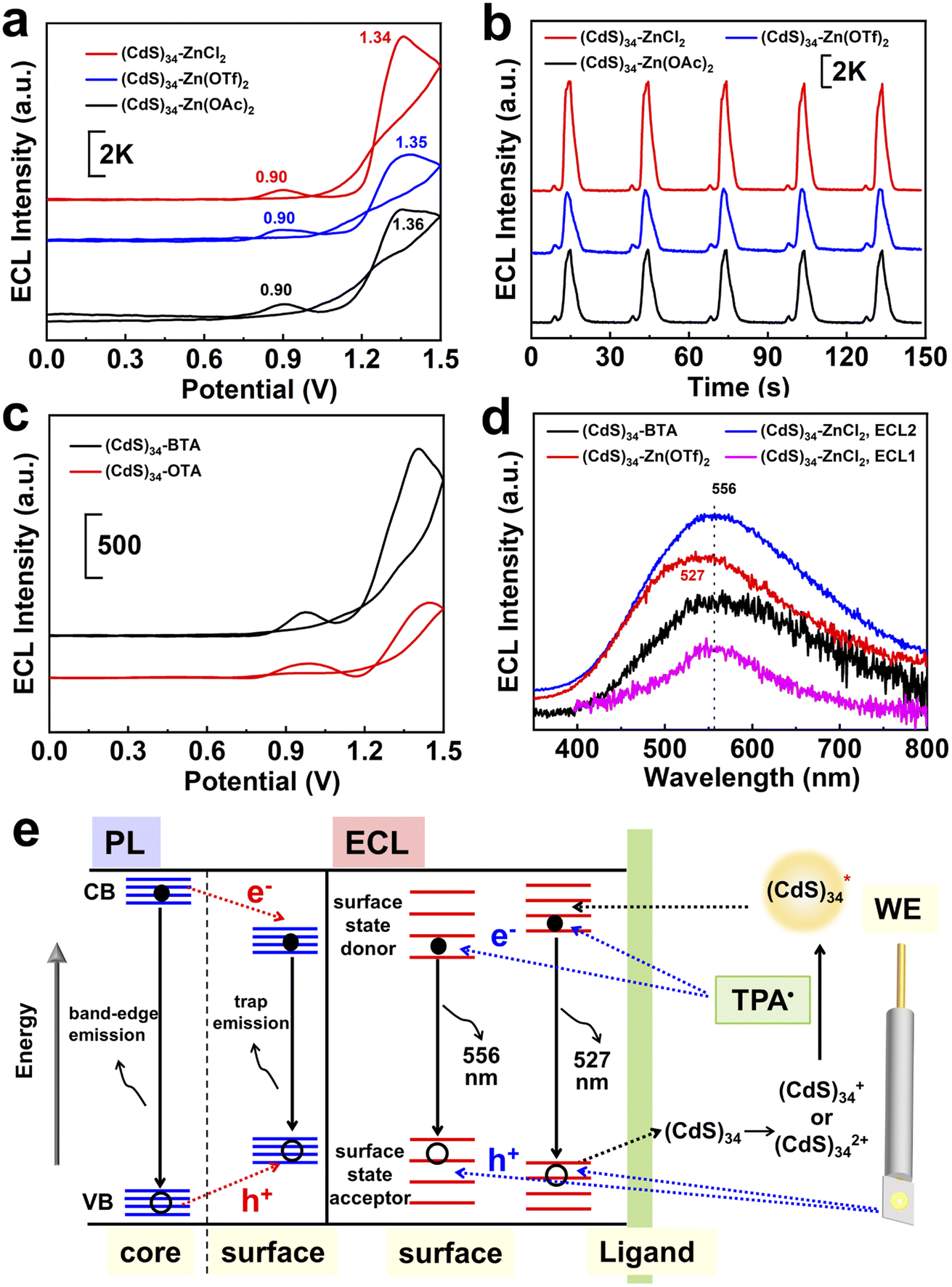 | ||
| Fig. 5 The ECL properties of MSCs: (a) ECL-V curves and (b) ECL-Time curves of (CdS)34-BTA (black), (CdS)34–Zn(OAc)2 (blue), (CdS)34–Zn(OTf)2 (red) and (CdS)34–ZnCl2 (green) MSCs. (c) ECL-V curves of (CdS)34-OTA (red) and (CdS)34-BTA (black) MSCs. (d) ECL spectra of (CdS)34-BTA, (CdS)34–ZnCl2 and (CdS)34–Zn(OTf)2 MSCs. (e) Schematic illustration of the mechanisms for PL and ECL of (CdS)34 MSCs. | ||
Likewise, we explored the ECL performance of other MSCs with different ligands. Metal salt-ligated (CdSe)34 MSCs (Fig. S7†) were obtained by the same ligand exchange procedure. (CdSe)34–ZnCl2 and (CdSe)34–Zn(OAc)2 demonstrated a 5-fold and 7.8-fold enhancement of the ECL intensity, respectively. In addition, we obtained all-inorganic (CdSe)34 MSCs stabilized in aqueous solution and their ECL intensities were enhanced by a factor of 5 (Fig. S8†).
Investigation of MSC surface states by ECL
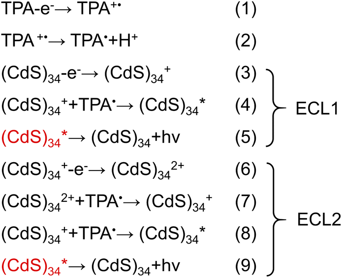
The large specific surface area of MSCs leads to a decisive influence of the surface state on the performance. Therefore, exploring the surface state of MSCs can provide insights into structure–function relationships at the molecular level. However, current techniques for MSC characterization cannot meet the needs of surface chemistry studies. For example, PL mainly focuses on exploring the properties of the core, and the spectral changes caused by different surface environments are not sufficient to reflect the specific surface state changes (Fig. 2b, c and 5e, left). The fluorescence lifetime can be used to monitor the changes on the surface, but the extremely short lifetime (approximately 0.05 ns) of MSCs leads to ambiguous characterization (Fig. S9†). Therefore, an alternative method is required to complement the traditional optical characterization for studying the surface chemistry of MSCs.ECL is the process wherein species generated at electrodes undergo high-energy electron-transfer reactions to form excited states that emit light, which is more sensitive to the surface environment of nanomaterials.35–39 To gain insight into the surface states affecting different ligands, we first sought to identify the ECL mechanism in MSC systems. The differential pulse voltammogram (DPV, Fig. S10†) of (CdS)34-BTA MSCs exhibits two oxidation waves, O1 and O2, at 0.851 V and 1.363 V, respectively, which were attributed to the oxidation reactions of the components in the selected semiconductor MSCs.40 This was evidenced by the persistence of the O1 and O2 oxidation peaks after triphenylphosphine (TPP) treatment to completely passivate MSCs, where TPP had been proven to selectively attach to chalcogenide sites on MSCs and stabilize the nonradiative trap state.22
Similar to the assignment of DPV peaks of metal clusters,41 O1 and O2 correspond to electrochemical reactions of (CdS)34+/(CdS)340 and (CdS)342+/(CdS)34+ oxidation couples, respectively (eqn (3) and (6)). This is further demonstrated by theoretical calculations, where the theoretical oxidation potentials of (CdS)34+/(CdS)340 and (CdS)342+/(CdS)34+ matched the experimental values (Table S4†). Meanwhile, the values of O1 and O2 were consistent with the potentials of ECL1 (0.96 V) and ECL2 (1.40 V) of (CdS)34-BTA MSCs, indicating that ECL1 and ECL2 correspond to the emission of (CdS)34+ and (CdS)342+ excited states. It is worth mentioning that the coreactant TPA underwent an oxidation process to form the corresponding TPA radical cation (TPA+˙), which was then rapidly deprotonated to generate highly reduced TPA˙ (eqn (1) and (2)). This oxidation process started at 0.8 V and peaked at 1.11 V (Fig. S11†). For ECL1 of (CdS)34 MSCs, the surface atoms of (CdS)34+ accept electrons from the coreactant radical TPA˙, forming the  excited state. ECL1 originated from
  emitting at 556 nm upon relaxation to its ground state (eqn (3)–(5)) (Fig. 5d). For ECL2 of (CdS)34 MSCs, the situation was slightly more complicated. The surface atoms of (CdS)342+ may accept either one electron from the coreactive radical TPA˙ to form
 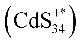 , or two electrons to form
  . Since ECL1 and ECL2 had the same emission wavelength (556 nm, Fig. 5d), indicating that their excited states were the same, ECL2 corresponded to the energy released when the
  excited state relaxed to the ground state by accepting two electrons (eqn (6)–(9)). The specific process is illustrated as follows:
After clarifying the ECL mechanism, we explored the relationship between the surface environment of the semiconductor MSCs and their ECL performance. Comparing Fig. 1c,2c and 5d, it is found that the ECL wavelength of each case was red-shifted by 149 nm ((CdS)34–Zn(OTf)2 MSCs) and 178 nm ((CdS)34-BTA and (CdS)34–ZnCl2 MSCs) from their PL band edge emission wavelengths. This trend was first observed in the MSC system and is consistent with that of NCs reported in the literature (∼200 nm, in CdSe QDs and silicon NCs).34,42,43 We attributed the difference between ECL and PL to the different radiation pathways, which was due to more surface defects and lower surface energy resulting in the surface states being located within the energy bandgap.33,42,43
For (CdS)34-BTA MSCs, L-type primary amine ligands were considered to provide two lone pairs of electrons to passivate the surface Cd atoms.44 Considering the coordination between ZnCl2 and NCs, we speculate that the interaction of the metal salt ligand and (CdS)34 MSCs should also be similar, that is, ZnCl2 interacts with Cd atoms (Fig. S12†). Quantitatively, the ICP-OES data indicate that there was 22% on the surfaces of each (CdS)34–ZnCl2 MSC, corresponding to 7.5 Zn atoms (Table S1†). We noticed that the ECL2 spectrum of all-inorganic (CdS)34–ZnCl2 MSCs was consistent with that of (CdS)34-BTA MSCs, both of which reached a maximum at 556 nm. However, the ECL spectrum may be the result of the combined effect of band gap emission and trap emission. Therefore, the ECL spectrum alone cannot fully reflect the defect state passivation of MSCs.
The ECL2 wavelength of all-inorganic (CdS)34–Zn(OTf)2 MSCs was significantly blue-shifted (527 nm, Fig. 5d), suggesting that the surface trap state was largely eliminated due to changes in surface passivation. Recently, Infante and co-workers demonstrated that two-coordinated chalcogenide atoms on the II–VI NC surface contributed to electronic states within the bad gap (trap states), which could be passivated by Z-type ligands.45,46 Therefore, we concluded that in our case Zn(OTf)2 also served as a neutral Z-type ligand to eliminate the two-coordinated chalcogenide atoms of the MSC surface (Fig. S12†). This passivation pattern was further confirmed by the disappearance of Zn form (82%) in the ICP-OES of (CdS)34–Zn(OTf)2 MSCs after treatment with TPP (Fig. S13†), which has been verified to selectively attach to S sites on the surface of the (CdS)34-BTA MSCs.22
As shown in Fig. 5e, two surface passivation modes of typical all-inorganic (CdS)34–ZnCl2 and (CdS)34–Zn(OTf)2 MSCs lead to different radiation pathways of the surface trap states, corresponding to two emissions at 556 and 527 nm, respectively. Thus, the ECL spectrum can clearly reflect the surface passivation of MSCs, providing a theoretical basis for the study of the surface states and properties of MSCs. In addition, we found that the ECL emission wavelength was red-shifted by 45 and 74 nm compared to the PL trap emission. On one hand, this could be attributed to the large self-absorption (inner filter effect) of emission from the solid ECL samples.47 On the other hand, the distance of the MSCs in the solid film on the electrode was smaller than that in the solution phase. Due to the enhanced electronic coupling effect, the quantum confinement effect of each MSC is reduced, resulting in a reduced band gap.48
Conclusion
In summary, we achieved surface modification of semiconductor MSCs through a mild ligand exchange strategy, which overcomes the difficulty of MSC surface design. All-inorganic (CdS)34, (CdSe)34 and (ZnSe)34 MSCs were obtained by replacing the original L-type ligands with designed metal salts without affecting their original compositions. We illustrated and verified the surface states (Cd passivation or S passivation) of the semiconductor MSCs by ECL spectroscopy. Through surface functionalization, the ECL performance of semiconductor MSCs was greatly improved, which could be attributed to the combined effect of the removal of the insulating barrier and the weakened hindering effect of all-inorganic ligands on electron tunneling. Our findings in designing a general surface treatment approach for MSCs and revealing the changes in MSC surface states with ligands provide new possibilities for not only rationally designing functional MSCs but also studying the structure–activity relationships of MSCs.Data availability
The data that support the findings of this study are available from the corresponding author upon reasonable request.Author contributions
Y. W. conceived the concept of this work. Y. W. and J. G. designed the experiments, analyzed the data and co-wrote the paper. J. L. and X. C. performed optical measurement with assistance from J. G. Y. D. and P. X. measured ICP-OES of MSCs. J. Z. provided suggestions on the experiments and manuscript. Y. W. supervised the project. All authors discussed the results and commented on the manuscript.Conflicts of interest
The authors declare no competing financial interests.Acknowledgements
We would like to thank Prof. Wenlei Zhu for the discussion and reading the manuscript. Y. W. thanks Dr Jie Pang for the suggestion on ECL measurements. This work was supported by the National Natural Science Foundation of China (No. 22171132), the Innovation Fund from Nanjing University (020514913419) and the Program for Innovative Talents and Entrepreneurs in Jiangsu (020513006012 and 020513006014).References
- M. S. Bootharaju, W. Baek, S. Lee, H. Chang, J. Kim and T. Hyeon, Small, 2021, 17, e2002067 CrossRef PubMed.
- C. Palencia, K. Yu and K. Boldt, ACS Nano, 2020, 14, 1227–1235 CrossRef CAS PubMed.
- A. B. Pun, S. Mazzotti, A. S. Mule and D. J. Norris, Acc. Chem. Res., 2021, 54, 1545–1554 CrossRef CAS PubMed.
- M. R. Friedfeld, J. L. Stein, A. Ritchhart and B. M. Cossairt, Acc. Chem. Res., 2018, 51, 2803–2810 CrossRef CAS PubMed.
- M. Liu, K. Wang, L. Wang, S. Han, H. Fan, N. Rowell, J. A. Ripmeester, R. Renoud, F. Bian, J. Zeng and K. Yu, Nat. Commun., 2017, 8, 15467 CrossRef CAS.
- Y. Wang, Y. H. Liu, Y. Zhang, F. Wang, P. J. Kowalski, H. W. Rohrs, R. A. Loomis, M. L. Gross and W. E. Buhro, Angew. Chem., Int. Ed. Engl., 2012, 51, 6154–6157 CrossRef CAS.
- A. Kasuya, R. Sivamohan, Y. A. Barnakov, I. M. Dmitruk, T. Nirasawa, V. R. Romanyuk, V. Kumar, S. V. Mamykin, K. Tohji, B. Jeyadevan, K. Shinoda, T. Kudo, O. Terasaki, Z. Liu, R. V. Belosludov, V. Sundararajan and Y. Kawazoe, Nat. Mater., 2004, 3, 99–102 CrossRef CAS PubMed.
- Y. Wang, Y. Zhang, F. Wang, D. E. Giblin, J. Hoy, H. W. Rohrs, R. A. Loomis and W. E. Buhro, Chem. Mater., 2014, 26, 2233–2243 CrossRef CAS PubMed.
- Y. Zhou, F. Wang and W. E. Buhro, Chem. Mater., 2020, 32, 8350–8360 CrossRef CAS.
- M. J. Bowers 2nd, J. R. McBride and S. J. Rosenthal, J. Am. Chem. Soc., 2005, 127, 15378–15379 CrossRef PubMed.
- W. Baek, M. S. Bootharaju, K. M. Walsh, S. Lee, D. R. Gamelin and T. Hyeon, Nat. Mater., 2021, 20, 650–657 CrossRef CAS.
- M. S. Bootharaju, W. Baek, G. Deng, K. Singh, O. Voznyy, N. Zheng and T. Hyeon, Chem, 2022 DOI:10.1016/j.chempr.2022.06.025.
- V. Singh, Priyanka, P. V. More, E. Hemmer, Y. K. Mishra and P. K. Khanna, Mater Adv, 2021, 2, 1204–1228 RSC.
- G. M. Carroll, R. Limpens and N. R. Neale, Nano Lett., 2018, 18, 3118–3124 CrossRef CAS PubMed.
- W. Xu, M. Wang, Z. Li, X. Wang, Y. Wang, M. Xing and Y. Yin, Nano Lett., 2017, 17, 2713–2718 CrossRef CAS PubMed.
- H. Zhang, B. Hu, L. Sun, R. Hovden, F. W. Wise, D. A. Muller and R. D. Robinson, Nano Lett., 2011, 11, 5356–5361 CrossRef CAS PubMed.
- E. L. Rosen, R. Buonsanti, A. Llordes, A. M. Sawvel, D. J. Milliron and B. A. Helms, Angew. Chem., Int. Ed. Engl., 2012, 51, 684–689 CrossRef CAS PubMed.
- A. Dong, X. Ye, J. Chen, Y. Kang, T. Gordon, J. M. Kikkawa and C. B. Murray, J. Am. Chem. Soc., 2011, 133, 998–1006 CrossRef CAS PubMed.
- Y. Wang, I. Fedin, H. Zhang and D. V. Talapin, Science, 2017, 357, 385–388 CrossRef CAS PubMed.
- M. V. Kovalenko, M. Scheele and D. V. Talapin, Science, 2009, 324, 1417–1420 CrossRef CAS PubMed.
- A. Nag, D. S. Chung, D. S. Dolzhnikov, N. M. Dimitrijevic, S. Chattopadhyay, T. Shibata and D. V. Talapin, J. Am. Chem. Soc., 2012, 134, 13604–13615 CrossRef CAS PubMed.
- S. Dolai, P. R. Nimmala, M. Mandal, B. B. Muhoberac, K. Dria, A. Dass and R. Sardar, Chem. Mater., 2014, 26, 1278–1285 CrossRef CAS.
- A. Nag, H. Zhang, E. Janke and D. V. Talapin, Z. Phys. Chem., 2015, 229, 85–107 CrossRef CAS.
- Y. Deng, X. Chen, J. Liang and Y. Wang, Front. Chem., 2022, 10, 860781 CrossRef CAS.
- J. Yang, X. Li, J. Zhang, Y. Zhou and Y. Wang, ACS Appl. Mater. Interfaces, 2022, 14(20), 22838–22846 CrossRef CAS PubMed.
- J. S. Son, K. Park, S. G. Kwon, J. Yang, M. K. Choi, J. Kim, J. H. Yu, J. Joo and T. Hyeon, Small, 2012, 8, 2394–2402 CrossRef CAS.
- Y. Wang, Y. Zhou, Y. Zhang and W. E. Buhro, Inorg. Chem., 2015, 54, 1165–1177 CrossRef CAS PubMed.
- E. Drijvers, J. De Roo, J. C. Martins, I. Infante and Z. Hens, Chem. Mater., 2018, 30, 1178–1186 CrossRef CAS.
- D. N. Dirin, S. Dreyfuss, M. I. Bodnarchuk, G. Nedelcu, P. Papagiorgis, G. Itskos and M. V. Kovalenko, J. Am. Chem. Soc., 2014, 136, 6550–6553 CrossRef CAS PubMed.
- J. Yang, R. Fainblat, S. G. Kwon, F. Muckel, J. H. Yu, H. Terlinden, B. H. Kim, D. Iavarone, M. K. Choi, I. Y. Kim, I. Park, H. K. Hong, J. Lee, J. S. Son, Z. Lee, K. Kang, S. J. Hwang, G. Bacher and T. Hyeon, J. Am. Chem. Soc., 2015, 137, 12776–12779 CrossRef CAS PubMed.
- C. H. Ho, P. Varadhan, H. H. Wang, C. Y. Chen, X. Fang and J. H. He, Nanoscale, 2016, 8, 5954–5958 RSC.
- Y. Liu, B. Zhang, H. Fan, N. Rowell, M. Willis, X. Zheng, R. Che, S. Han and K. Yu, Chem. Mater., 2018, 30, 1575–1584 CrossRef CAS.
- N. Myung, Y. Bae and A. J. Bard, Nano Lett., 2003, 3, 1053–1055 CrossRef CAS.
- L. Sun, L. Bao, B. R. Hyun, A. C. Bartnik, Y. W. Zhong, J. C. Reed, D. W. Pang, H. D. Abruna, G. G. Malliaras and F. W. Wise, Nano Lett., 2009, 9, 789–793 CrossRef CAS PubMed.
- Y. Zhang, X. Yan, D. Liu and G. Jie, Sens. Actuators, B, 2022, 362 Search PubMed.
- C. Ma, S. Wu, Y. Zhou, H. F. Wei, J. Zhang, Z. Chen, J. J. Zhu, Y. Lin and W. Zhu, Angew. Chem., Int. Ed. Engl., 2021, 60, 4907–4914 CrossRef CAS PubMed.
- Y. Cao, Y. Zhou, Y. Lin and J. J. Zhu, Anal. Chem., 2021, 93, 1818–1825 CrossRef CAS PubMed.
- J. Ge, X. Chen, J. Yang and Y. Wang, Analyst, 2021, 146, 803–815 RSC.
- Q. Cai, D. Wu, H. Li, G. Jie and H. Zhou, Biosens. Bioelectron., 2021, 191, 113455 CrossRef CAS PubMed.
- F. Wang, J. Lin, T. Zhao, D. Hu, T. Wu and Y. Liu, J. Am. Chem. Soc., 2016, 138, 7718–7724 CrossRef CAS PubMed.
- M. Hesari and Z. Ding, Acc. Chem. Res., 2017, 50, 218–230 CrossRef CAS PubMed.
- Z. Ding, B. M. Quinn, S. K. Haram, L. E. Pell, B. A. Korgel and A. J. Bard, Science, 2002, 296, 1293–1297 CrossRef CAS PubMed.
- N. Myung, Z. Ding and A. J. Bard, Nano Lett., 2002, 2, 1315–1319 CrossRef CAS.
- N. C. Anderson, M. P. Hendricks, J. J. Choi and J. S. Owen, J. Am. Chem. Soc., 2013, 135, 18536–18548 CrossRef CAS PubMed.
- A. J. Houtepen, Z. Hens, J. S. Owen and I. Infante, Chem. Mater., 2017, 29, 752–761 CrossRef CAS.
- N. Kirkwood, J. O. V. Monchen, R. W. Crisp, G. Grimaldi, H. A. C. Bergstein, I. du Fosse, W. van der Stam, I. Infante and A. J. Houtepen, J. Am. Chem. Soc., 2018, 140, 15712–15723 CrossRef CAS PubMed.
- M. M. Sartin, C. Shu and A. J. Bard, J. Am. Chem. Soc., 2008, 130, 5354–5360 CrossRef CAS PubMed.
- M. V. Kovalenko, M. I. Bodnarchuk, J. Zaumseil, J. S. Lee and D. V. Talapin, J. Am. Chem. Soc., 2010, 132, 10085–10092 CrossRef CAS PubMed.
Footnote |
| † Electronic supplementary information (ESI) available: Experimental details, characterization techniques, and supplementary figures. See https://doi.org/10.1039/d2sc03868d |
| This journal is © The Royal Society of Chemistry 2022 |