 Open Access Article
Heterostructured FeNi hydroxide for effective electrocatalytic oxygen evolution†
Fayan
Li
ab,
Yanyan
Li
ab,
Lei
Li
ab,
Wen
Luo
c,
Zhouguang
Lu
 c,
Xinyu
Zhang
*ab and
Zhiping
Zheng
 *ab
*ab
aDepartment of Chemistry, Guangdong Provincial Key Laboratory of Energy Materials for Electric Power, Southern University of Science and Technology (SUSTech), Shenzhen 518055, China. E-mail: zhangx1@sustech.edu.cn; zhengzp@sustech.edu.cn
bKey Laboratory of Energy Conversion and Storage Technologies, SUSTech, Ministry of Education, Shenzhen 518055, China
cDepartment of Materials Science and Engineering, SUSTech, Shenzhen 518055, China
First published on 15th July 2022
Abstract
Hydrogen production technology by water splitting has been heralded as an effective means to alleviate the envisioned energy crisis. However, the overall efficiency of water splitting is limited by the effectiveness of the anodic oxygen evolution reaction (OER) due to the high energy barrier of the 4e− process. The key to addressing this challenge is the development of high-performing catalysts. Transition-metal hydroxides with high intrinsic activity and stability have been widely studied for this purpose. Herein, we report a gelatin-induced structure-directing strategy for the preparation of a butterfly-like FeNi/Ni heterostructure (FeNi/Ni HS) with excellent catalytic performance. The electronic interactions between Ni2+ and Fe3+ are evident both in the mixed-metal “torso” region and at the “torso/wing” interface with increasing Ni3+ as a result of electron transfer from Ni2+ to Fe3+ mediated by the oxo bridge. The amount of Ni3+ also increases in the “wings”, which is believed to be a consequence of charge balancing between Ni and O ions due to the presence of Ni vacancies upon formation of the heterostructure. The high-valence Ni3+ with enhanced Lewis acidity helps strengthen the binding with OH− to afford oxygen-containing intermediates, thus accelerating the OER process. Direct evidence of FeNi/Ni HS facilitating the formation of the Ni–OOH intermediate was provided by in situ Raman studies; the intermediate was produced at lower oxidation potentials than when Ni2(CO3)(OH)2 was used as the reference. The Co congener (FeCo/Co HS), prepared in a similar fashion, also showed excellent catalytic performance.
Introduction
With the increasing challenges associated with the energy crisis and environmental pollution, it is of paramount significance to develop renewable and clean energies.1–3 Hydrogen gas, with its high energy density and sole combustion product being water, is considered as the most attractive energy carrier.4,5 Water splitting has been the primary means for hydrogen production. The process entails two half-reactions, namely the hydrogen evolution reaction (HER) and the oxygen evolution reaction (OER). The OER, involving four electrons in the process, occurs at the anode and is recognized as the “bottleneck” challenge due to its sluggish kinetics.6–8 Transition-metal hydroxides with high intrinsic activity and stability in the presence of alkaline electrolytes have been the focus of recent research as potential efficient electrocatalysts to address this challenge.9–13 When compared with single-metal hydroxides, bimetallic hydroxides are more attractive due to the possible electronic interactions between the two different metal sites that may lead to the fine-tuning of the electronic properties of the active sites for improvement of catalytic properties and the resulting facilitated generation and transformation of oxy-containing intermediates.14–17 Impressive progress notwithstanding, the presently known bimetallic hydroxides have yet to meet the standard for desirable performance; further development in this vein is thus warranted.Constructing heterointerfaces and relying on the anticipated synergy between the components is a general strategy for obtaining high-performing catalysts.18–21 Traditional strategies for constructing heterostructures include the soft-template method,22 hydrothermal synthesis,23,24 electrodeposition,25–27 and electrostatic adsorption.28 However, most of these methods involve multiple steps that are generally complicated and energy-consuming, and are not suitable for large-scale preparation. Therefore, a simple, low-cost, and universally applicable strategy is highly desirable for the preparation of bimetallic heterostructured hydroxides. Gelatin, a biodegradable and environmentally friendly surfactant, is rich in functional groups (–CO–NH2, –COOH, –NH2) that are capable of coordinating various metal ions to induce directional growth of molecular and material structures with different chemical compositions and morphologies.29–32
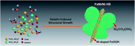
With this recognition, a butterfly-like bimetallic FeNi/Ni hydroxide heterostructure (FeNi/Ni HS) featuring a mixed-metal (FeNi) “torso” and two “wings” of pure Ni with “torso–wing” (FeNi) interfaces was successfully prepared by gelatin-induced preparation (Scheme 1). We showed its excellent electrocatalytic performance for the OER by a series of comparative studies with reference to its single-metal (Ni and Fe) analogs. Its electronic structure was analyzed by using X-ray photoelectron spectroscopy (XPS) and electron energy loss spectroscopy (EELS) from which the Ni2+-to-Fe3+ electron transfer via the oxo bridge can be inferred. The resulting increase of Ni3+, together with the Ni vacancies facilitates the formation of Ni–OOH – the key intermediate preceding the release of O2 as revealed by in situ Raman spectroscopy.
Results and discussion
Structural and morphological characterization
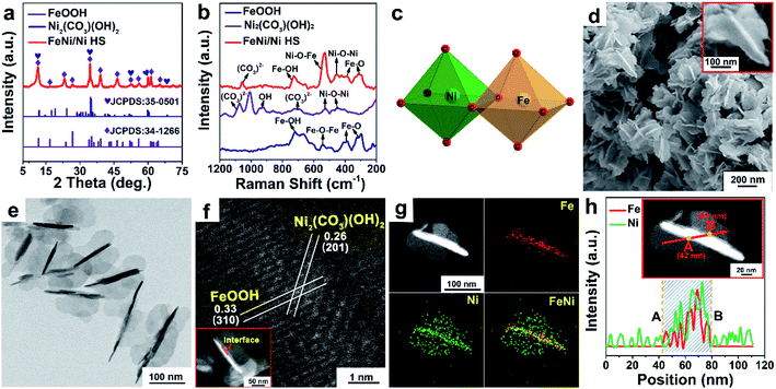
The XRD pattern of FeNi/Ni HS (Fig. 1a) shows the combined peaks of FeOOH (JCPDS: 34-1266) and Ni2(CO3)(OH)2 (JCPDS: 35-0501). The crystal structure simulations (Fig. S1a and b†) show the building units of the skeletal structure being MO6 octahedra. The two peaks at 310 cm−1 and 380 cm−1 in the Raman spectrum of FeNi/Ni HS (Fig. 1b) correspond to the Fe–O vibration mode of octahedral Fe sites, while the peak at 720 cm−1 corresponds to the Fe–OH vibration.33 The peak at 450 cm−1 is attributable to the vibration of Ni–O–Ni, while the one at 1058 cm−1 can be assigned to the vibration of CO32−.34 Significantly, the peak associated with the vibration of Ni–O–Fe of FeNi/Ni HS is found around 530 cm−1.35 These results confirmed that FeNi/Ni HS consists of FeOOH and Ni2(CO3)(OH)2 with both being constructed with the octahedral MO6 units and that the oxo-bridged octahedral units feature certain units of Ni–O–Fe due to the partial replacement of the Fe by Ni (Fig. 1c).The morphology of FeNi/Ni HS was studied by SEM and TEM. The SEM image (Fig. 1d) showed a butterfly-like structure (inset 1d) featuring a “torso” of ca. 150 (length) × 20 nm (width), flanked by two “wings” of ca. 50 nm (width). The butterfly-like structures with the length in the range between 100 and 150 nm and the width at ca. 100 nm are further shown in the TEM images (Fig. 1e and S2†). High-resolution lattice fringes of the interface are clearly shown in the HAADF-STEM image (Fig. 1f). The interplanar spacing of 0.33 nm within the “torso” can be indexed to the (310) plane of FeOOH with that of 0.26 nm in the “wings” to the (201) plane of Ni2(CO3)(OH)2. The EDX elemental mapping (Fig. 1g and h) showed that the presence of Ni is concentrated in the “wings” while both Fe and Ni are present within the “torso”, indicating a higher concentration of Ni than Fe in the heterostructure, which is also consistent with the results obtained by inductively coupled plasma (ICP) analysis (Table S1†). HAADF-STEM, EDX-mapping, and EELS were used to explore the location and electronic state of the “torso” Ni sites (Fig. S3†); they, as isolated atoms, are incorporated into the lattice of FeOOH to afford Ni-doped FeOOH. On the basis of the results by XRD and Raman spectroscopic analyses, it is reasonable to conclude that the “torso” is made primarily of Ni-doped FeOOH, while the “wings” are made essentially of pure Ni2(CO3)(OH)2.
Synthesis mechanism
The present gelatin-induced formation of the heterostructure was made possible by the large number of metal-coordinating functional groups including –CO–NH2, –COOH, and –NH2 in gelatin (Fig. S4†). Preferential growth of a particular structure may be induced due to the differences in the coordination modes of these functional groups.36,37 In this work, the gradual development of the butterfly-like heterostructure is clearly shown in the time-dependent evolution of FeNi/Ni HS as monitored by the EDX elemental mapping over a course of 36 hours. Specifically, four distinct stages, namely the formation of nanorods, nanorods with burrs, fragmental nanorods, and butterfly-like nanorods (Fig. 2 and S5†), are observed along the course of the heterostructure development. Specifically, 3 hours after the reaction with a mixture of FeCl3·6H2O, NiCl2·6H2O, urea, and gelatin, nanorods with co-existing Fe/Ni metal ions were observed (Fig. 2a and S5a†). Upon extending the reaction time to 6 hours, epitaxial growth on the nanorods occurred, producing nanorods with burrs that contained only Ni as indicated by EDX elemental mapping (Fig. 2b and S5b, c†). Further extending the reaction time to 18 hours resulted in the continuous growth of the burrs into plate-like fragments; only Ni was found in these fragments (Fig. 2c and S5d–f†). The butterfly-like heterostructure was achieved upon further extending the growth process up to 36 hours (Fig. 2d and S5g, h†). The change of the contents of Ni and Fe over this course is summarized in Table S2.† Besides, other reaction conditions including the amount of gelatin and urea, and the metal/organic stoichiometry have also been found to influence the morphology of the resulting heterostructures (Fig. S6†). Of particular note is the further epitaxial growth of the “wings” as the amount of Ni in the reaction mixture increased. This observation is consistent with the aforementioned concentration of only Ni in the wings when the reaction time was extended.Electrocatalytic performance
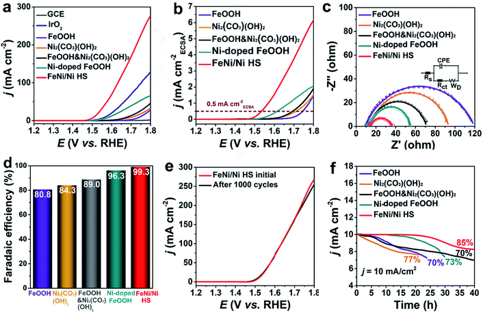
A series of experiments were used to evaluate the catalytic performance of FeNi/Ni HS with references to FeOOH and Ni2(CO3)(OH)2 (Fig. S7†) where appropriate. The linear sweep voltammetry curve (LSV) is shown in Fig. 3a. The onset overpotential of 220 mV for FeNi/Ni HS is significantly lower than those of FeOOH, Ni2(CO3)(OH)2, a mixture of FeOOH and Ni2(CO3)(OH)2 (FeOOH&Ni2(CO3)(OH)2), Ni-doped FeOOH, commercial IrO2, and GCE. Its overpotential of 268 mV to reach a current density of 10 mA cm−2 is also much lower than those of the comparison group. The corresponding catalytic performance of heterostructures with different Ni/Fe ratios has also been evaluated, and we found the heterostructure with a Ni/Fe ratio of 3/2 showing the best performance (Fig. S8†). This sample was then used for comparative studies discussed below.The electrochemical active surface area (ECSA)-normalized current density (jECSA) is a parameter indicating the intrinsic activity of a catalyst and can be estimated from the electric double-layer capacitance (Cdl, Fig. S9†) obtained from a non-Faraday interval cyclic voltammetry curve (CV, Fig. S10†). As indicated by the ECSA-normalized current curves (Fig. 3b), FeNi/Ni HS operated with the lowest overpotential at 0.5 mA cmECSA−2, indicating that the heterostructured catalyst is the most active one, followed by Ni-doped FeOOH, FeOOH&Ni2(CO3)(OH)2, Ni2(CO3)(OH)2, and FeOOH.38,39 The mass activity (MA) and turnover frequency (TOF) of the catalysts were estimated (Table 1) with FeNi/Ni HS exhibiting the highest MA of 35.00 A g−1 and TOF of 0.0160 s−1. Furthermore, electrochemical impedance plots (EIS, Fig. 3c) show a charge transfer resistance (Rct) of 26 Ω for FeNi/Ni HS. This value, much smaller than those obtained for the catalysts in the comparison group (FeOOH 109 Ω, Ni2(CO3)(OH)2 82 Ω, FeOOH&Ni2(CO3)(OH)2 61 Ω, and Ni-doped FeOOH 45 Ω), indicates a much-enhanced charge-transfer characteristic of the heterostructured catalyst. The Nyquist plots, showing the feature of double-layer capacitance, were fitted by the equivalent circuit (inset Fig. 3c).
| Materials | Onset potential (V vs. RHE) | Overpotentiala (mV) | MA (A g−1) | TOF (s−1) |
|---|---|---|---|---|
| a At a current density of 10 mA cm−2. | ||||
| FeNi/Ni HS | 1.45 | 268 | 35.00 | 0.0160 |
| FeOOH | 1.65 | 514 | 0.36 | 0.0002 |
| Ni2(CO3)(OH)2 | 1.56 | 480 | 1.40 | 0.0006 |
| FeOOH&Ni2(CO3)(OH)2 | 1.55 | 450 | 2.24 | 0.0010 |
| Ni-doped FeOOH | 1.50 | 353 | 3.30 | 0.0014 |
| IrO2 | 1.53 | 340 | — | — |
The faradaic efficiencies of the catalysts were also calculated (Fig. 3d and S11†) with FeNi/Ni HS producing the largest ring current of 39.7 μA (collection efficiency 0.2) among the comparison group and the highest faradaic efficiency of 99.3%.40,41
Long-term durability is necessary for practical applications. FeNi/Ni HS showed only a slight decrease of current density at high potential (Fig. 3e) after 1000 cycles. Moreover, chronopotentiometry measurement (Fig. 3f) shows that 85% of its original activity was maintained after 40 h of operation at 10 mA cm−2. This stability performance is much better than that of the catalysts in the comparison group. TEM, XRD and XPS characterizations were used to further assess the stability of FeNi/Ni HS after long-term tests. The TEM image (Fig. S12a†) showed little morphological changes. In addition, the XRD patterns of the samples before and after the experiments (Fig. S12b†) are essentially the same. The valence states of the elements in the samples before and after the OER tests were evaluated by comparative XPS studies. While the binding energy of Fe 2p peaks remained essentially unchanged (Fig. S13a†), those of Ni 2p3/2 and Ni 2p1/2 (Fig. S13b†) shift to more positive values after the OER test, suggesting an increase of the higher-valance Ni3+ when compared with the sample before the test. This increase is corroborated by the decrease in the ratio of Ni2+/Ni3+ from 1.87 to 1.53, indicative of the oxidation of Ni2+.42 In addition, we also compared FeNi/Ni HS with other transition metal-based catalysts (Table S3†); this heterostructured catalyst clearly possesses activity and stability that are superior to those in the literature.
Mechanistic analysis
As catalysis is primarily a surface-determined event, the most important factor affecting the activity of a catalyst is the electronic structure of the surface-bound atoms. To probe the electronic structures of these active sites, we conducted a series of comparative studies in order to differentiate between distinct regions of the heterostructure.To explore the electronic structures of Ni and Fe in FeNi/Ni HS, XPS analyses were undertaken. The Fe 2p spectrum (Fig. 4a) is fitted into two pairs of peaks, corresponding to Fe3+ (710.6 eV, 724.5 eV) and Fe2+ (707.0 eV and 723.0 eV),24,42 respectively. Compared with the FeOOH reference, the binding energies of Fe 2p electrons in FeNi/Ni HS are lowered by 0.7 eV, indicating an increase of electron density due to the increase of Fe2+. This assessment is corroborated by the increase of Ni3+ in FeNi/Ni HS as the binding energies of Ni 2p electrons in the heterostructure show a positive shift by 0.3 eV with respect to the reference Ni2(CO3)(OH)2 (Fig. 4b).43,44 Together, these oxidation-state changes may be attributable to the Ni2+-to-Fe3+ electron transfer upon formation of the heterostructured catalyst.
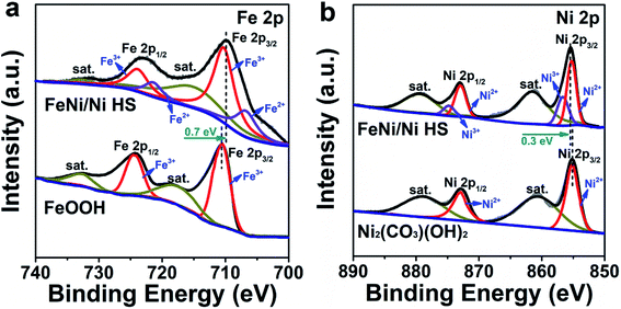 | ||
| Fig. 4 XPS spectra of (a) Fe 2p and (b) Ni 2p electrons for FeNi/Ni HS with reference to FeOOH and Ni2(CO3)(OH)2, respectively. | ||
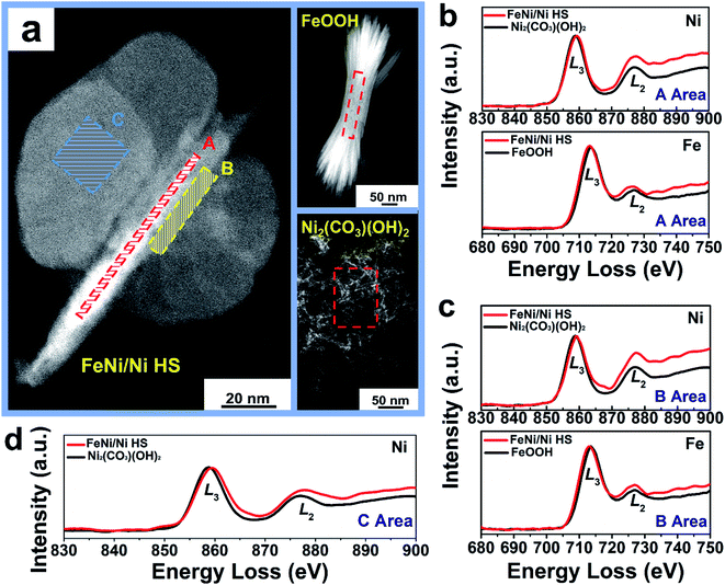
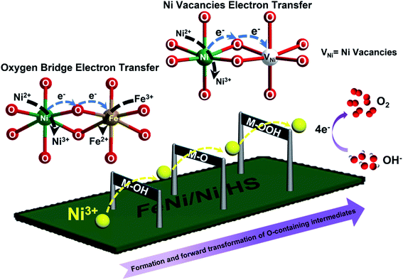
Atomic electronic structure, in particular the valence state, is sensitively dependent on the chemical environment of the atoms of interest.45 With respect to the references FeOOH and Ni2(CO3)(OH)2, comparative electronic structure analyses by EELS of the “torso” (region A), the “torso–wing” interface (region B), and the “wing” (region C) of FeNi/Ni HS reveal the disparate electronic structures of the metal ions in these different regions of the heterostructure (Fig. 5a). Specifically, the area ratio of the Fe L2,3 edges is 2.40, while that in region A (“torso”) of FeNi/Ni HS is 2.26 (Fig. 5b and Table 2); the decrease by 5.8% indicates an increase of Fe2+ upon formation of the heterostructure.46 An analogous analysis of the Ni L3/L2 edge area ratio in the same region revealed a decrease by 17.5% from 1.43 for Ni2(CO3)(OH)2 to 1.18 for the heterostructure, which is indicative of an increase of Ni3+.47 In other words, both Fe2+ and Ni3+ increase in this region. The same conclusion can be reached qualitatively for the torso–wing interface (region B) on the basis of the EELS analyses (Fig. 5c and Table 2). These results unambiguously suggest the occurrence of electron transfer between Ni2+ and Fe3+ in the “torso” and at the “torso–wing” interface of the heterostructure and presumably by way of the Ni–O–Fe linkage: the π-symmetry d-orbitals (t2g, 3d8) of Ni2+ are filled with electrons, causing an electronic repulsion between Ni2+ and the bridging O2− (2p6). In comparison, the t2g (3d5) orbitals of Fe3+ are half-filled. As such, it is reasonable to assume that electron transfer occurred initially via π-donation from the bridging O2− to Fe3+; this event is followed by a subsequent shift of electron density from Ni2+ to O2−, leading to the net Ni2+-to-Fe3+ electron transfer (Fig. S14†).48
In the wings (region C), the Ni L3/L2 edge area ratio is 1.29, decreasing from 1.43 of Ni2(CO3)(OH)2 and suggesting an increase of Ni3+ (Fig. 5d and Table 2). This increase of Ni3+ can be attributed to the presence of Ni vacancies from intrinsic Ni2(CO3)(OH)2 (Fig. S15a†) upon formation of the heterostructure as required by the charge balancing between Ni and O ions; there are simply not enough Ni2+ ions to balance the negative charge of O2− from CO32− and OH− in Ni2(CO3)(OH)2. As such, an enhancement of the oxidation state from Ni2+ to Ni(2 + δ)+ is anticipated (Fig. S15b†).49
With the above results, a mechanism possibly responsible for the observed catalytic OER by FeNi/Ni HS is schematically illustrated in Fig. 6. The increase of the higher-valence Ni3+ upon formation of the heterostructure within the “torso” and at the “torso–wing” interface is believed to be primarily responsible for the enhanced catalytic performance observed. With respect to other metal ions (Fe3+/Fe2+/Ni2+) present, the more strongly Lewis acidic Ni3+ ions facilitate and strengthen the binding and thus activation of OH− at the initial stage of the catalysis and forge ahead with the forward and successive transformation of the oxygen-containing intermediates (M–OH, M–O, M–OOH), leading eventually to the accelerated OER.
The specific enhancing effect of FeNi/Ni HS in promoting the formation and transformation of the oxygen-containing intermediates was investigated by in situ Raman spectroscopy (Fig. 7 and S16†). As shown in Fig. 7a, the peaks at 450 and 530 cm−1 up to 1.3 V are attributed to the Ni–O vibrations.50 Starting from 1.4 V and up, two new peaks, characteristic of the vibrations of the Ni–OOH intermediate, appear at 553 and 475 cm−1 accompanied by the disappearance of the original Ni–O vibration peaks.51,52 In contrast, with the use of Ni2(CO3)(OH)2 as the reference catalyst, the Ni–OOH vibration peaks did not appear until 1.5 V (Fig. 7b). Notably, the Raman spectrum of FeOOH (Fig. S16†) does not show any noticeable changes during this process, suggesting that (1) Fe2+/3+ ions are not directly involved in the formation of the oxygen-containing intermediates; and (2) the electronic structure changes brought about upon forming the heterostructure, primarily in the increase of Ni3+, are responsible for the facilitated OER as evidenced by the facilitated formation of Ni–OOH – the key intermediate immediately preceding the release of O2 in the OER process.
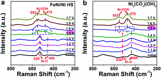 | ||
| Fig. 7 Monitoring the formation of the Ni–OOH intermediate during the OER by in situ Raman spectroscopy; (a) FeNi/Ni HS was used as the catalyst versus (b) Ni2(CO3)(OH)2 as the reference. | ||
Extension of the preparation method to the construction of heterostructured FeCo/Co HS
The gelatin-induced genesis and growth of mixed-metal hydroxide heterostructures was validated further by the successful preparation of congenic FeCo/Co HS (Fig. S17†) using CoCl2·6H2O in place of NiCl2·6H2O under otherwise identical preparative conditions. Catalytic property investigation indicated that FeCo/Co HS also outperformed FeOOH, Co(CO3)0.5(OH), a physical mixture of FeOOH and Co(CO3)0.5(OH) (FeOOH&Co(CO3)0.5(OH)), Co-doped FeOOH, and IrO2.Conclusions
We report in this work a general gelatin-induced synthetic strategy for constructing bimetallic heterostructured hydroxides. A butterfly-like FeNi/Ni heterostructure featuring a “torso” flanked by two “wings” with two distinct “torso–wing” interfaces was obtained and showed superior electrocatalytic performance for the OER. XPS and EELS analyses indicated that both Ni3+ and Fe2+ increase in the “torso” and “torso–wing” regions, due supposedly to the Ni2+-to-Fe3+ electron transfer by way of oxo bridges. The presence of Ni vacancies in the “wings” also causes the increase of Ni3+ ions when compared with pure Ni2(CO3)(OH)2. The highly Lewis acidic Ni3+ ions facilitate and strengthen the association of OH− at the initial stage of the catalysis, thus accelerating the formation and forward transformation of the oxygen-containing intermediates. Ni–OOH – the intermediate immediately preceding the release of O2 was indeed observed by in situ Raman spectroscopy at a lower potential than when Ni2(CO3)(OH)2 was used as the reference. The obtainment of an analogous high-performing heterostructured FeCo/Co catalyst suggests that the present gelatin-induced synthetic approach may be really applicable for the preparation of other electrocatalytically active mixed-metal hydroxides.Data availability
The data supporting the findings of this study are available in the manuscript and the ESI.†Author contributions
F. Y. L. performed the experimental work, data analysis, drafting, and revision of the manuscript. Y. Y. L. and L. L. helped with data collection and analyses, and manuscript revision. W. L. assisted in collecting the in situ Raman spectroscopic data and handling the data processing. Z. G. L. supervised the use of the in situ Raman spectrometer and offered valuable discussion of the results. X. Y. Z. conducted conceptualization and supervision of the project, data analyses, and writing and editing of the manuscript. Z. P. Z. conducted conceptualization, funding acquisition, project administration, and editing of the manuscript.Conflicts of interest
The authors declare no competing financial interest.Acknowledgements
We gratefully acknowledge the financial support by Shenzhen Nobel Prize Scientists Laboratory Project (Grant No. C17213101, Z. Z.), Guangdong Provincial Key Laboratory of Catalysis (No. 2020B121201002, Z. Z.), Guangdong Provincial Key Laboratory of Energy Materials for Electric Power (2018B030322001, Z. Z.), A Start-up Fund from SUSTech (Y01216127, Y01216227, Z. Z.), Post-doctorate Scientific Research Fund for staying in (coming to) Shenzhen (K21217502, X. Z.), and Basic Research Project of the Science and Technology Innovation Commission of Shenzhen (JCYJ20190809115413414, Z. L.). This work was also partially supported by the start-up fund from Southern University of Science and Technology. The authors also acknowledge the assistance of Southern University of Science and Technology Core Research Facilities (SUSTech CRF) and Key Laboratory of Energy Conversion and Storage Technologies (Southern University of Science and Technology).Notes and references
- J. Eom, M. Hyun, J. Lee and H. Lee, Nat. Energy, 2020, 5, 976–984 CrossRef.
- J. Wang, J. Wang, Z. Kong, K. Lv, C. Teng and Y. Zhu, Adv. Mater., 2017, 29, 1703044 CrossRef PubMed.
- S. S. Wu, Y. G. Zhu, Y. F. Huo, Y. C. Luo, L. H. Zhang, Y. Wan, B. Nan, L. J. Cao, Z. Y. Wang, M. C. Li, M. Y. Yang, H. Cheng and Z. G. Lu, Sci. China Mater., 2017, 60, 654–663 CrossRef CAS.
- H. L. Van, L. Laffineur, R. Campe, P. Perreault, S. W. Verbruggen and S. Lenaerts, Energy Environ. Sci., 2021, 14, 815–843 RSC.
- Q. Zhou, Z. Shen, C. Zhu, J. Li, Z. Ding, P. Wang, F. Pan, Z. Zhang, H. Ma, S. Wang and H. Zhang, Adv. Mater., 2018, 30, 1800140 CrossRef PubMed.
- R. Chen, S. F. Hung, D. Zhou, J. Gao, C. Yang, H. Tao, H. B. Yang, L. Zhang, Q. Xiong, H. M. Chen and B. Liu, Adv. Mater., 2019, 31, 1903909 CrossRef CAS PubMed.
- R. Liu, Y. Wang, D. Liu, Y. Zou and S. Y. Wang, Adv. Mater., 2017, 29, 1701546 CrossRef PubMed.
- Y. Wang, L. Yan, K. Dastafkan, C. Zhao, X. Zhao, Y. Xue, J. Huo, S. Li and Q. Zhai, Adv. Mater., 2021, 33, 2006351 CrossRef CAS PubMed.
- J. Kang, X. Qiu, Q. Hu, J. Zhong, X. Gao, R. Huang, C. Wan, L. M. Liu, X. Duan and L. Guo, Nat. Catal., 2021, 4, 1050–1058 CrossRef CAS.
- Z. P. Wu, X. F. Lu, S. Q. Zang and X. W. Lou, Adv. Funct. Mater., 2020, 30, 1910274 CrossRef CAS.
- A. C. Garcia, T. Touzalin, C. Nieuwland, N. Perini and M. T. M. Koper, Angew. Chem., Int. Ed., 2019, 58, 12999–13003 CrossRef CAS PubMed.
- O. Diaz-Morales, I. Ledezma-Yanez, M. T. M. Koper and F. CalleVallejo, ACS Catal., 2015, 5, 5380–5387 CrossRef CAS.
- C. Kuai, C. Xi, A. Hu, Y. Zhang, Z. Xu, D. Nordlund, C. J. Sun, C. A. Cadigan, R. M. Richards, L. Li, C. K. Dong, X. W. Du and F. Lin, J. Am. Chem. Soc., 2021, 143, 18519–18526 CrossRef CAS PubMed.
- J. Chen, F. Zheng, S. J. Zhang, A. Fisher, Y. Zhou, Z. Wang, Y. Li, B. B. Xu, J. T. Li and S. G. Sun, ACS Catal., 2018, 8, 11342–11351 CrossRef CAS.
- L. Trotochaud, S. L. Young, J. K. Ranney and S. W. Boettcher, J. Mater. Chem. A, 2014, 136, 6744–6753 CAS.
- X. Y. Xiong, Z. Cai, D. J. Zhou, G. X. Zhang, Q. Zhang, Y. Jia, X. X. Duan, Q. X. Xie, S. B. Lai, T. H. Xie, Y. P. Li, X. M. Sun and X. Duan, Sci. China Mater., 2018, 61, 939–947 CrossRef CAS.
- P. Acharya, R. H. Manso, A. S. Hoffman, S. I. Perez Bakovic, L. Kékedy-Nagy, S. R. Bare, J. Chen and L. F. Greenlee, ACS Catal., 2022, 12, 1992–2008 CrossRef CAS.
- Z. An, H. Ma, H. Han, Z. Huang, Y. Jiang, W. Wang, Y. Zhu, H. Song, X. Shu, X. Xiang and J. He, ACS Catal., 2020, 10, 12437–12453 CrossRef CAS.
- W. Chen, B. Wu, Y. Wang, W. Zhou, Y. Li, T. Liu, C. Xie, L. Xu, S. Du, M. Song, D. Wang, Y. Liu, Y. Li, J. Liu, Y. Zou, R. Chen, C. Chen, J. Zheng, Y. Li, J. Chen and S. Y. Wang, Energy Environ. Sci., 2021, 14, 6428–6440 RSC.
- J. X. Feng, S. H. Ye, H. Xu, Y. X. Tong and G. R. Li, Adv. Mater., 2016, 28, 4698–4703 CrossRef CAS PubMed.
- Z. W. Gao, J. Y. Liu, X. M. Chen, X. L. Zheng, J. Mao, H. Liu, T. Ma, L. Li, W. C. Wang and X. W. Du, Adv. Mater., 2019, 31, 1804769 CrossRef PubMed.
- Q. Zhang, W. Xiao, W. H. Guo, Y. X. Yang, J. L. Lei, H. Q. Luo and N. B. Li, Adv. Funct. Mater., 2021, 31, 2102117 CrossRef CAS.
- J. H. Li, L. L. Wang, H. J. He, Y. Q. Chen, Z. R. Gao, N. Ma, B. Wang, L. L. Zheng, R. L. Li, Y. J. Wei, J. Q. Xu, Y. Xu, B. W. Cheng, Z. Yin and D. Ma, Nano Res., 2022, 15, 4986–4995 CrossRef CAS.
- K. Z. Li, B. C. Zhao, J. Bai, H. Y. Ma, Z. T. Fang, X. B. Zhu and Y. P. Sun, Small, 2020, 16, 2001974 CrossRef CAS PubMed.
- T. Y. Liu and P. Diao, Nano Res., 2020, 13, 3299–3309 CrossRef CAS.
- M. Y. Zheng, K. L. Guo, W. J. Jiang, T. Tang, X. Y. Wang, P. P. Zhou, J. Du, Y. Q. Zhao, C. L. Xu and J. S. Hu, Appl. Catal., B, 2019, 244, 1004–1012 CrossRef CAS.
- J. Lv, L. Wang, R. Li, K. Zhang, D. Zhao, Y. Li, X. Huang and G. Wang, ACS Catal., 2021, 11, 14338–14351 CrossRef CAS.
- B. Shao, Z. Liu, G. Zeng, Y. Liu, Q. Liang, Q. He, T. Wu, Y. Pan, J. Huang, Z. Peng, S. Luo, C. Liang, X. Liu, S. Tong and J. Liang, Appl. Catal., B, 2021, 286, 119867 CrossRef CAS.
- X. Liu, C. Kan, X. Wang, X. Yang and L. Lu, J. Am. Chem. Soc., 2006, 128, 430–431 CrossRef CAS PubMed.
- H. Nassira, A. Sanchez-Ferrer, J. Adamcik, S. Handschin, H. Mahdavi, T. N. Qazvini and R. Mezzenga, Adv. Mater., 2016, 28, 6914–6920 CrossRef CAS PubMed.
- J. J. Calvin, A. S. Brewer and A. P. Alivisatos, Nat. Synth., 2022, 1, 127–137 CrossRef.
- S. Dhakal, K. L. Kohlstedt, G. C. Schatz, C. A. Mirkin and M. O. Cruz, ACS Nano, 2013, 7, 10948–10959 CrossRef CAS PubMed.
- J. Hu, S. Li, J. Chu, S. Niu, J. Wang, Y. Du, Z. Li, X. Han and P. Xu, ACS Catal., 2019, 9, 10705–10711 CrossRef CAS.
- L. Peng, N. Yang, Y. Yang, Q. Wang, X. Xie, D. Sun-Waterhouse, L. Shang, T. Zhang and G. I. N. Waterhouse, Angew. Chem., Int. Ed., 2021, 60, 24612–24619 CrossRef CAS PubMed.
- J. T. Kloprogge, L. Hickey and R. L. Frost, J. Raman Spectrosc., 2004, 35, 967–974 CrossRef CAS.
- X. Zang, W. S. Chen, X. L. Zou, J. N. Hohman, L. J. Yang, B. X. Li, M. S. Wei, C. H. Zhu, J. M. Liang, M. Sanhadasa, J. J. Gu and L. W. Lin, Adv. Mater., 2018, 30, 1805188 CrossRef PubMed.
- M. Helminger, B. H. Wu, T. Kollmann, D. Benke, D. Schwahn, V. Pipich, D. Faivre, D. Zahn and H. Cölfen, Adv. Funct. Mater., 2014, 24, 3187–3196 CrossRef CAS PubMed.
- X. H. Sun, Q. Shao, Y. C. Pi, J. Guo and X. Q. Huang, J. Mater. Chem. A, 2017, 5, 7769 RSC.
- D. Voiry, M. Chhowalla, Y. Gogotsi, N. A. Kotov, Y. Li, R. M. Penner, R. E. Schaak and P. S. Weiss, ACS Nano, 2018, 12, 9635–9638 CrossRef CAS PubMed.
- H. L. Fei, J. C. Dong, Y. X. Feng, C. S. Allen, C. Z. Wan, B. Volosskiy, M. F. Li, Z. P. Zhao, Y. L. Wang, H. T. Sun, P. F. An, W. X. Chen, Z. Y. Guo, C. Lee, D. L. Chen, I. Shakir, M. J. Liu, T. D. Hu, Y. D. Li, A. I. Kirkland, X. F. Duan and Y. Huang, Nat. Catal., 2018, 1, 63 CrossRef CAS.
- T. Y. Ma, S. Dai, M. Jaroniec and S. Z. Qiao, J. Am. Chem. Soc., 2014, 136, 13925 CrossRef CAS PubMed.
- C. Ye, J. Liu, Q. Zhang, X. Jin, Y. Zhao, Z. Pan, G. Chen, Y. Qiu, D. Ye, L. Gu, G. I. N. Waterhouse, L. Guo and S. Yang, J. Am. Chem. Soc., 2021, 143, 14169–14177 CrossRef CAS PubMed.
- C. Cao, D. D. Ma, Q. Xu, X. T. Wu and Q. L. Zhu, Adv. Funct. Mater., 2019, 29, 1807418 CrossRef.
- H. Li, S. Chen, Y. Zhang, Q. Zhang, X. Jia, Q. Zhang, L. Gu, X. Sun, L. Song and X. Wang, Nat. Commun., 2018, 9, 2452 CrossRef PubMed.
- Y. Tian, X. Liu, L. Xu, D. Yuan, Y. Dou, J. Qiu, H. Li, J. Ma, Y. Wang, D. Su and S. Zhang, Adv. Funct. Mater., 2021, 31, 2101239 CrossRef CAS.
- C. Wang, D. R. Baer, J. E. Amonette, M. H. Engelhard, J. Antony and Y. Qiang, J. Am. Chem. Soc., 2009, 131, 8824–8832 CrossRef CAS PubMed.
- X. Ren, C. Wei, Y. Sun, X. Liu, F. Meng, X. Meng, S. Sun, S. Xi, Y. Du, Z. Bi, G. Shang, A. C. Fisher, L. Gu and Z. J. Xu, Adv. Mater., 2020, 32, 2001292 CrossRef CAS.
- J. Jiang, F. F. Sun, S. Zhou, W. Hu, H. Zhang, J. C. Dong, Z. Jiang, J. J. Zhao, J. F. Li, W. S. Yan and M. Wang, Nat. Commun., 2018, 9, 2885 CrossRef PubMed.
- Y. J. Wu, J. Yang, T. X. Tu, W. Q. Li, P. F. Zhang, Y. Zhou, J. F. Li, J. T. Li and S. G. Sun, Angew. Chem., Int. Ed., 2021, 60, 26829–26836 CrossRef CAS PubMed.
- L. Bai, S. Lee and X. Hu, Angew. Chem., Int. Ed., 2021, 60, 3095–3103 CrossRef CAS PubMed.
- J. Zhang, J. Liu, L. Xi, Y. Yu, N. Chen, S. Sun, W. Wang, K. M. Lange and B. Zhang, J. Am. Chem. Soc., 2018, 140, 3876–3879 CrossRef CAS PubMed.
- C. F. Li, L. J. Xie, J. W. Zhao, L. F. Gu, H. B. Tang, L. R. Zheng and G. R. Li, Angew. Chem., Int. Ed., 2022, 61, e202116934 CAS.
Footnote |
| † Electronic supplementary information (ESI) available. See https://doi.org/10.1039/d2sc02767d |
| This journal is © The Royal Society of Chemistry 2022 |

