
 Open Access Article
 This Open Access Article is licensed under a Creative Commons Attribution-Non Commercial 3.0 Unported Licence
Microflow chemistry and its electrification for sustainable chemical manufacturing†
Tai-Ying
Chen‡
a,
Yung Wei
Hsiao‡
a,
Montgomery
Baker-Fales‡
 a,
Fabio
Cameli
a,
Panagiotis
Dimitrakellis
ab and
Dionisios G.
Vlachos
*ab
a,
Fabio
Cameli
a,
Panagiotis
Dimitrakellis
ab and
Dionisios G.
Vlachos
*ab
aDepartment of Chemical and Biomolecular Engineering, University of Delaware, 150 Academy Street, Newark, Delaware 19716, USA. E-mail: vlachos@udel.edu
bCatalysis Center for Energy Innovation, RAPID Manufacturing Institute, Delaware Energy Institute (DEI), University of Delaware, 221 Academy St., Newark, Delaware 19716, USA
First published on 6th August 2022
Abstract
Sustainability is vital in solving global societal problems. Still, it requires a holistic view by considering renewable energy and carbon sources, recycling waste streams, environmentally friendly resource extraction and handling, and green manufacturing. Flow chemistry at the microscale can enable continuous sustainable manufacturing by opening up new operating windows, precise residence time control, enhanced mixing and transport, improved yield and productivity, and inherent safety. Furthermore, integrating microfluidic systems with alternative energy sources, such as microwaves and plasmas, offers tremendous promise for electrifying and intensifying modular and distributed chemical processing. This review provides an overview of microflow chemistry, electrification, their integration toward sustainable manufacturing, and their application to biomass upgrade (a select number of other processes are also touched upon). Finally, we identify critical areas for future research, such as matching technology to the scale of the application, techno-economic analysis, and life cycle assessment.
1 Introduction
Sustainability is key to the well-being of society and is a holistic grand challenge which, in the context of the chemicals industry, includes three main domains: product, feedstock, and manufacturing (Fig. 1). While making end products, the current economy creates a large volume of waste streams, including food and agricultural waste, lignin from the paper industry, lubricants, tires, methane leaks from shale gas wells, plastic waste, etc. Circularity and upcycling can mitigate this issue.1–3 In the former, one recycles the product at its life's end to its constituents to build back the product. In the latter, one seeks to make higher-value products than the recycled one to extend the lifetime of the entire chain.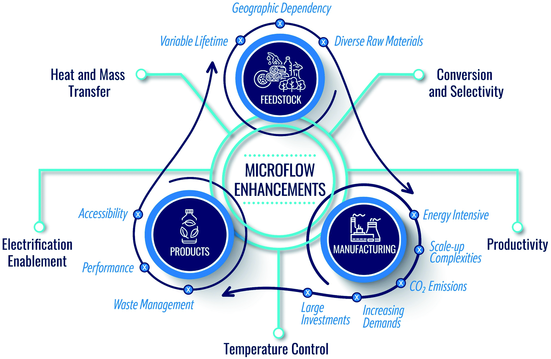 | ||
| Fig. 1 Domains of sustainability in the chemical industry and the manner by which microflows can support and enhance the circular economy. | ||
With the depletion of fossil fuels (conventional feedstock), global warming, and increased demand stemming from a growing population and improved living standards, circularity alone cannot achieve sustainability. Renewable sources are needed. Therefore, researchers have focused on utilizing renewable feedstocks in the past twenty years (Fig. 1). Many efforts have been devoted to using biomass as carbon source, developing electrochemical devices for CO2 conversion, hydrogen production via water splitting, and other chemicals and artificial photosynthesis for solar fuels.4–8
Importantly, due to atom and energy inefficiencies in manufacturing, chemical reactors and separations require significant energy, producing copious amounts of CO2. It is thus imperative to consider sustainable manufacturing in conjunction with product circularity and feedstock availability (Fig. 1). However, in our view, the sustainability of chemical manufacturing has received less attention compared to the other two domains. Driving the industry into zero-emissions requires significant technological advances. Chemical manufacturing needs to sustain the natural resources and the ecosystem while ensuring product quality. The cores of sustainable development include resource availability, improved atom and energy efficiency, and minimal environmental footprint. Green chemistry and engineering values for the design of products, processes, and manufacturing9–12 embody 12 principles (P),9 summarized in Fig. 2.
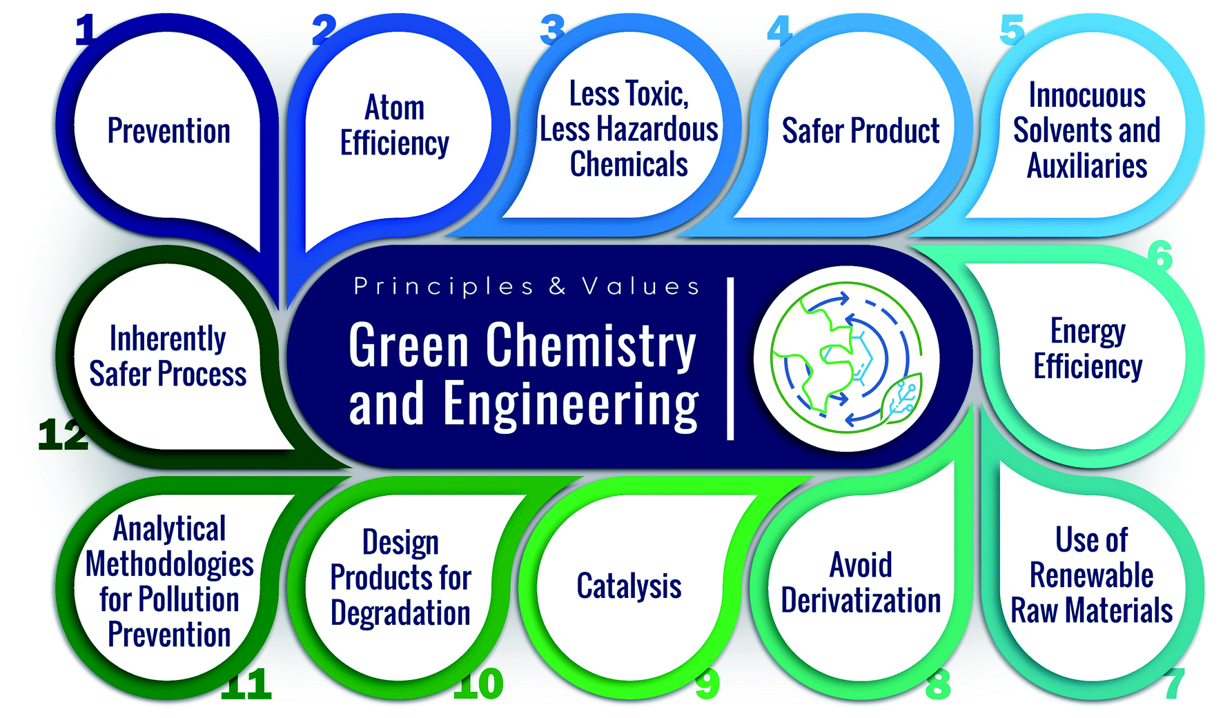 | ||
| Fig. 2 Green chemistry and engineering principles. | ||
Continuous manufacturing using microfluidics can achieve several of these principles, benefitting from small reactor sizes, fast mixing, precise temperature control, effective heat management, and high energy efficiency (Fig. 1).13–15 For example, the reduced solvent volumes in microreactors minimize waste and environmental burden (P1). The enhanced mixing and transport can improve atom efficiency by increasing product yield and selectivity and reducing byproducts (P2, P9). Temperature control and fast heat transfer broaden the operation window, enhancing energy and atom efficiency (P2, P6) and reducing the energy requirements (P6). The precise heat management and the small volumes of processed hazardous materials make the processes safer (P3, P4, P12).
Because of these advantages, microflow chemistry has emerged as a central pillar of green catalytic engineering for processing renewable sources (P7), such as biomass,16 as the most accessible and reliable renewable carbon source. Agricultural waste, such as corn stover and sugarcane, food waste, such as potato and orange peels, energy crops, etc., are promising feedstocks as they do not interfere with edible biomass and land or have negative ecological impacts.16–19 Lignocellulose, in the microfibrils of the cell walls of plants, consists mainly of polysaccharides and lignins.20–22 During the past twenty years, efforts have been devoted to transforming lignocellulosic biomass into fuels, chemicals, and other products and developing catalysts, (batch) processes, and mechanistic insights. These chemistries become more efficient (P2) in microreactors due to enhanced product yield and selectivity.23–25
Biomass usually contains a significant amount of water and requires considerable energy for transportation to refineries.26–28 As a result, onsite processing is necessary. The same applies to food waste, a vast volume, short lifetime feedstock. While plastic waste has a long lifetime (estimated to be hundreds of years) and low water content, it is spread in landfills and ecosystems. On-site processing in remote and offshore locations is essential. Microflow chemistry can provide better economic viability and higher energy efficiency (P6), supporting sustainable on-site manufacturing.
Since current chemical manufacturing depends on natural gas combustion, producing a tremendous amount of greenhouse gas emissions (GHG), achieving a zero-emissions industry requires alternative energy from solar, wind, and geothermal. Joule or direct resistive heating, inductive heating, ultrasound, microwaves, plasmas, and electrosynthesis are such electrification technologies that can use green electricity to minimize GHG emissions profoundly. Electrification can provide rapid and selective heating or alternative reaction pathways, minimize side reactions, and reduce the use of solvents (P1, P8). These technologies usually offer high energy efficiency (P6) and intensification, allowing compact devices and lower capital investments. These advantages make electrification a perfect match with microflow technology. As a result, their integration is an emerging topic for sustainable chemical production.
Despite good reviews13,15,22,29–36 on the design of microfluidics15,30,33,36 and their application to organic synthesis, nanoparticles synthesis, and active pharmaceutical ingredient production,13,32,34,35 their deployment for renewable sources has been limited, and their electrification has not been reviewed. This paper provides an overview of microfluidics, their electrification, and their application to the processing of renewable resources.
2 Design and engineering of microreactors
Microreactors expose unique flow patterns, enhanced heat and mass transfer,37–39 fast mixing, and precise residence time and temperature control, thus greatly influencing chemical reactions. Microreactors' internal/hydraulic diameter is typically below 3 mm, and the Reynolds number (Re) is often below 250.13 Their walls are usually made of hydrophobic (i.e., polyether ether ketone (PEEK), perfluoro alkoxy alkane (PFA), and polytetrafluoroethylene (PTFE)) or hydrophilic (i.e., fused silica, glass, and stainless steel) materials. The material properties control the continuous phase that wets the surface and the flow patterns. This section gives a brief overview of the essential features of microreactors for chemical manufacturing.2.1 Flow patterns
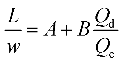
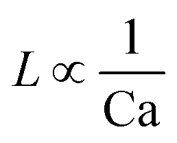
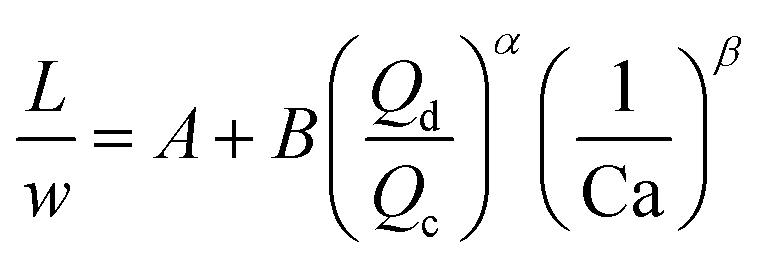
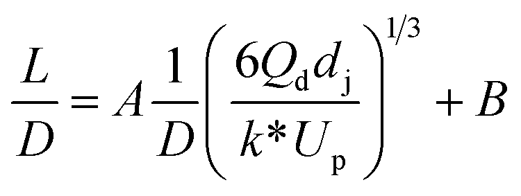
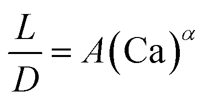
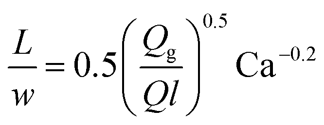
For the past two decades, micro-scale flows have been studied extensively. Single-phase microreactors consist of a liquid or gas phase. Liquid-phase microreactors entail a homogeneous catalyst mixed with a solvent and reactants flowing through them.40–42 When a solid catalyst is employed, it is usually coated on the channel wall. The use of additional phases can enable simultaneous separation or tandem reactions. In biphasic systems, two relatively immiscible fluids (a gas–liquid or a liquid–liquid) come in contact. A common goal of microtechnology is rapid mixing. Various flow patterns can occur in micromixers upon contact of phases. Commonly used micromixers are generally passive and include simple contacting structures43 (T-junction, Y-junction, cross-junction, and co-flowing junction), multilamination structures,44 and split-recombine structures.45 Different micromixers yield different flow patterns. Observed flow patterns include slug, droplet, parallel, annular, dispersed, slug-droplet, and irregular flow. The patterns depend on the physical properties of the solvents (density, viscosity, and surface tension), the wettability, the device diameter, the geometry of the wall, the flow rate, and the fraction of each phase.46–48 Segmented flow (slug flow and droplet flow) and parallel/annular flow are common. In the former, alternating fluid segments occur, where the wall-wetting (continuous) phase usually forms a thin film around the non-wetting (dispersed) phase. When the flow rate is low, the slugs are shear off from the micromixer junction due to the dominant of interfacial tension, enabling the sharp break-up of the slugs.49 When the flow rate increases, the dispersed phase flows into the downstream microchannel, and a long tail forms before the slugs are shear off since the viscous force increases, and the interfacial tension is not sufficient for quick and sharp break-up.49 At an even higher flow rate, the tails become longer, and the slugs become smaller. Eventually, the flow turns into the latter, the liquids flow side by side. A homogeneous catalyst is in one phase, whereas the other phase serves as an extracting solvent to remove target chemicals50–52 and enhance product yield and selectivity by preventing side reactions23,24,53 from happening in the catalyst-containing phase. The length of the slugs, droplets, or bubbles affects mass transfer.54–57 The length is usually predicted using semi-empirical relations (Table 1) for a simple contacting reactor. These invoke the capillary number (Ca), i.e., the ratio between the viscous force and interfacial tension, of the dispersed and continuous phases, due to the interfacial tension and viscous force dominating over the inertia in microchannels. Also, the flow rate ratio of the continuous to dispersed flow plays a vital role in deciding the slug/droplet size. The slug length decreases with increasing continuous to dispersed flow rate ratio.58 In consideration of the governing forces, such as interfacial tension, viscous force, and inertia, there are also different dimensionless groups affecting the flow pattern formation: Reynolds number (Re) is the ratio between inertia and viscous force; Weber number (We) describes the relative importance between inertia and interfacial tension; Ohnesorge number (Oh) compares the viscous force to the product of inertia and interfacial tension; and Bonds number (Bo) characterizes the ratio between gravity to interfacial tension.58 These dimensionless groups act as the useful descriptor for flow pattern generation.59 A careful design of the microchannels and operating conditions is needed to obtain the desired flow pattern. For complex micromixers, computational fluid dynamics (CFD) can resolve the fluid–fluid interface and provide the flow pattern.60–63| Flow pattern | Formulaa |
|---|---|
| a L is the slug or droplet length; w is the microchannel width; Q represents the flow rate; subscript d denotes the dispersed phase; subscript c denotes the continuous phase; subscript g denotes the gas phase; subscript l denotes the liquid phase; dj represents the jet neck diameter; k* is the dimensionless wavenumber of the maximum growth rate of capillary perturbation; Up is the jet velocity; D demonstrates the inner diameter of the microchannel; A, B, α, and β are the fitted parameters. | |
| Liquid–liquid slug or droplet formed in the squeezing regime using a T-junction mixer64 |
|
| Liquid–liquid droplet formed in the dripping regime using a co-flowing or T-junction mixer65 |
|
| Liquid–liquid droplet formed in the transient regime between the squeezing and dripping regime using a T-junction mixer64 |
|
| Liquid–liquid droplet formed in the jetting flow using a co-flowing mixer66 |
|
| Liquid–liquid droplet formed in the dripping flow using a flow-focusing mixer67 |
|
| Gas–liquid slug flow using a T-junction mixer68 |
|
Catalyst particles or solid reagents are packed into a micropacked bed or are mixed with a solvent to create a slurry.69,70 Micropacked beds provide a high catalyst loading, a large surface area, and inherent mixing but suffer from a high-pressure drop. They are widely used in biomass derivatives' conversion,71 such as hydrogenation72 and oxidation,73 and the majority of their applications for multiphase reactions is gas–liquid–solid system.71 Strong capillary force in the micro-scale leads to higher liquid holdups in the micropacked beds.74 Moreover, particle size, reactor geometry, and the superficial velocity also affect the flow pattern and the transient time to achieve steady state operation.75 These parameters also affect the interfacial surface area and the external mass transfer in a micropacked bed.76,77 Decreasing particle size and increasing superficial velocity enhances the mass transfer.77 Alternatively, coating a heterogeneous catalyst on the inner wall of microreactors lowers the pressure at the expense of a lower catalyst surface area. These different configurations greatly impact the flow distribution and mass transfer, and thus, the reaction performance.
2.2 Intensified mixing and transport
Many chemical reactions involve multiple co-reactants and a catalyst. Achieving homogeneity in the solution is important. The mixing is typically affected by fluid dynamics. The timescale of mixing can significantly influence the selectivity and yield.78 Mixing in laminar flow happens by molecular diffusion. In a single-phase system, the characteristic diffusion time is proportional to the square of the characteristic length (L) and inversely proportional to the diffusivity (D), as in eqn (1),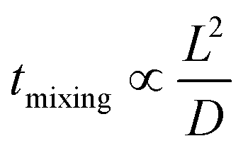 | (1) |
The small dimension of microreactors results in a short diffusion path and fast mixing, enabling uniform distribution of reagents and catalysts in a solvent. The mixing time is significantly decreased compared to a conventional size reactor. In this regard, micromixers and microreactors of very short characteristic diffusion lengths are ideal.
An immiscible solvent can create secondary flows in a segmented flow, enhancing mixing within the slugs or droplets and the mass transfer due to inner circulations. The interfacial mass transfer rate increases dramatically depending on the flow patterns, the flow rates, and the geometry. It is usually described by the volumetric mass transfer coefficient (kLa), which is the product of the intrinsic mass transfer coefficient (kL) and the interfacial surface area (a). Acetone or succinic acid between water and an organic phase is commonly used to estimate the interfacial mass transfer in liquid–liquid systems.54 The CO2/DEA (diethanolamine) system is used for gas–liquid systems.79 In general, the mass transfer rate increases when total flow rate increases due to the reduced interfacial diffusion layer and enhanced internal circulations.80–82 When the flow rate ratio increases, kLa increases with hydrophobic channel walls and decreases with hydrophilic channel walls.83–85 This is attributed to whether the aqueous phase is dispersed or continuous, leading the enhancement or reduction of the interfacial surface area.86 Aside from this, microchannel materials also affect the mass transfer by providing different contact angles. Surface modifications of microchannel wall can increase kLa due to enhancement of mixing and improvement of the interfacial surface area.87kLa typically increases with decrement of microchannel diameter due to the reduction of the diffusion length. kLa in a microreactor is typically 2 to 3 orders of magnitude higher than in a conventional reactor88,89 due to the secondary flows,90 the small slugs and droplets, and the high specific surface area. Fig. 4a and b clearly shows the inner circulations within the slugs and droplets. The interfacial mass transfer is mainly driven by convection in the axial direction. It is only fast in the middle of the slugs and droplets and their edges. The mass transfer in the radial direction is slow and is driven by diffusion. Susanti et al.91 proposed eqn (2) to evaluate kLa in a microreactor as a function of material properties, operating conditions, and slug length.
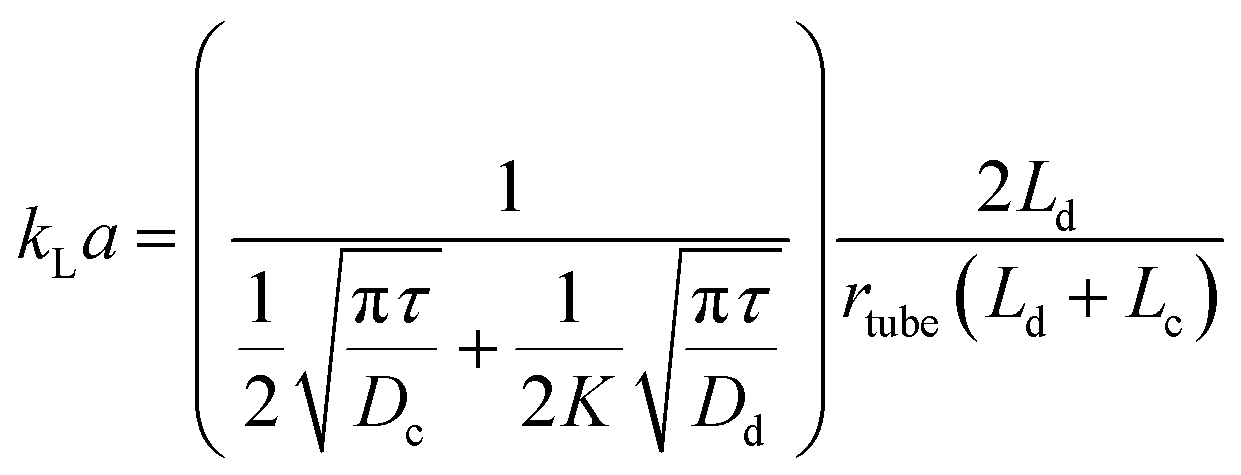 | (2) |
| Flow pattern | Correlationa |
|---|---|
| a D h is the hydraulic diameter of the microchannel; τ is the residence time; D demonstrates the inner diameter of the microchannel; L represents the length of the microchannel; subscript g denotes the gas phase; subscript l denotes the liquid phase; Q represents the flow rate; U is the superficial velocity; ε demonstrates the flow rate ratio of aqueous to the organic phase. | |
| Gas–liquid slug flow formed using a T-junction mixer95 | k L a = 0.0002219Reg0.3245Rel0.7764Scl0.5 |
| Gas–liquid slug flow formed using a T-junction mixer96 | ShlaDh = 0.094Reg0.0656Rel0.654Scl1.449Ca0.839 |
| Liquid–liquid slug flow formed using a Y-junction mixer97 |
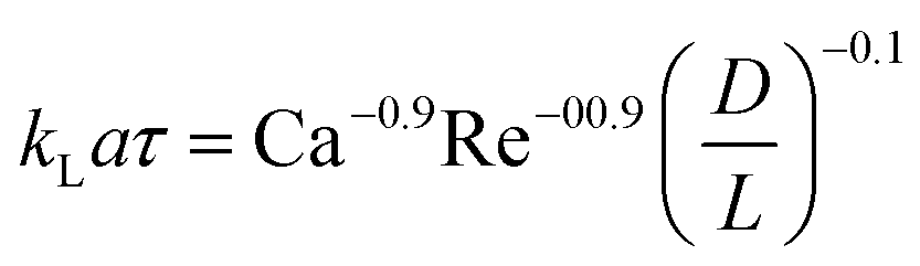
|
| Liquid–liquid droplet flow formed using a T-junction mixer98 | k L a = 2.12 × 10⁻⁶Q−0.34U0.53D−1.99 |
| Liquid–liquid droplet flow formed using a cross-flow T-junction mixer99 |
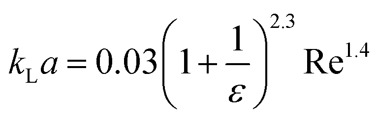
|
Microreactors also possess fast heat transfer, enabling precise temperature control and accurate measurement of chemical reaction kinetics. Due to dissipating the reaction energy rapidly, microreactors are suitable for highly exothermic reactions.32 The biphasic slug flow provides better heat transfer than the single-phase flow due to the internal circulations inside both dispersed and continuous slugs, which greatly enhance the heat transfer between phases.100 The recirculation in the continuous slug also alters the boundary layer.101 Shorter slug length and higher heat Péclet number, which is the ratio between convective and diffusive transport rate, lead to faster heat transfer.102 The microchannel geometry and film thickness between the slug and the channel wall affect the heat transfer as well. Even though heat transfer between the fluid and the wall has been studied extensively, a few studies have focused on heat transfer between liquid phases. An extracting phase or inert components offer merit, such as absorbing the excess reaction heat from a reacting phase for an exothermic reaction. Considering the heat and mass transfer analogy, such interfacial heat transfer would also be affected by flow patterns. The heat conductive transport is generally much faster than the mass diffusive transport for the liquid, i.e., heat diffusivity is larger than mass diffusivity, making heat transfer in a parallel or annular flow faster than mass transfer.
2.3 Controlling residence time distribution and broadening operation windows
The fast heat and mass transfer in microreactors can shift reactions from transport control to kinetics control.35 Moreover, the residence time distribution (RTD) in a microreactor is narrower,103 enabling better control of the reaction time than a typical continuous stirred-tank reactor. This is attributed to the enhanced convective mixing and the inner circulations in slugs and droplets.104 The RTD is affected by the microreactor geometry. For instance, serpentine reactor, coiled reactor, and arc flow inverter lead to narrow RTD by improving mixing or leveraging Dean vortexes.28,104,105 Active volume in the microreactor can be >99% of nominal volume with careful design, indicating that dead volume is negligible.106 The RTD of a biphasic flow can be close to the Dirichlet function.107 For example, narrow RTDs occur for water–toluene and gas–liquid segmented flow.103 Although the residence time may be affected by catalyst deactivation in long-time operations,108 precise measurement of intrinsic kinetics is enabled using microreactors,35 even when unstable, reactive intermediates occur. The residence time is controlled by the length of the microchannel or the flow rate. By simply decreasing the microreactor length, it is possible to directly measure the intermediates or transform them in a second reactor,23 making reactions that are hard to perform in a typical batch reactor feasible. For example, oxidation of alcohols to aldehydes or ketones using dimethyl sulfoxide is carried out at −50 °C in a batch reactor to avoid the decomposition of the unstable, reactive intermediates.109 In contrast, a microreactor can be operated at room temperature due to its short residence times,109 minimizing energy consumption. Leveraging the precise and tunable residence time, a wider operating window can be safely achieved even in harsh conditions. For example, a high-temperature superheated flow microreactor is achievable for fructose dehydration, o-phenylenediamine condensation, and Kolbe–Schmitt reaction in very short residence times,28,110,111 In addition, the precise residence time control makes chemical synthesis without auxiliary protecting substances possible. For instance, Macbecin I can be directly obtained via an alternative synthesis without protecting the amino group.112 This enhances the atom efficiency of the production. Additional examples utilizing these benefits to convert renewable resources are discussed in the sections below.3 Lignocellulosic biomass conversion in microflow
The conversion of renewable biomass into functional platform chemicals and eventually ready-to-use fuels, chemicals, and other products, can mitigate the growing CO2 emissions (P3, P7). Most biomass transformations have been discovered and optimized in batch reactors. Batch reactors are convenient for discovery, as one does not have to worry about control of flowrates, phases, pressure build-up, catalyst deactivation, reactor plugging, etc. However, batch systems have several limitations. First, heating typical laboratory batch Parr systems is slow (it takes 20–30 min, depending on the final temperature) and temperature uniformity cannot be well controlled when scaling up due to heat transfer limitation. Consequently, batch reactors are unfit for high temperatures and short contact times operation for high productivity. We demonstrate below that broadening the operation window to short residence times with precise temperature control using continuous system is crucial for enhanced performance. Second, biphasic batch systems utilized for biomass valorization are often transport-limited; mass and heat transfers are greatly enhanced in microreactors (P6). Last but not least, the large volume of biomass and chemicals call for continuous flow operation, as commonly done in chemical manufacturing. These benefits will be discussed in this section of the review.A continuous flow microreactor can bridge discovery with industrial practice while providing enhanced transport between phases and maximizing yields at high temperatures and ultra-short residence times. Furthermore, biomass is generated in rural areas where small, portable systems allow local-to-the-source processing while ensuring low capital costs, fast processing times, compact units, and lower-risk investments. Process intensification (PI) is essential to ensure modularity with enhanced energy efficiency and fewer emissions. Data collection time and automation in microreactors (e.g., time on stream, process variable variations) are highly suited for future digitalization. They are unmatched compared to conducting a single or a couple of measurements per day in batch systems.113 In this section, the catalytic conversion of monosaccharides to furanic derivatives using homogeneous and heterogeneous monophasic and biphasic reactors is reviewed. Productivity is a crucial advantage of continuous flow reactors and is used as a comparison metric. Due to the high cost of raw materials, the selectivity to desired products, also discussed here, is the most critical metric for economics.
3.1 Homogeneous catalytic reactors
Homogeneous monophasic or biphasic microfluidic systems precisely control reaction conditions for optimal performance, something unattainable in batch systems. One can carry out ultra-fast reactions at low residence time, with rapid heating due to reduced thermal inertia and increased mixing and mass transfer between phases. These characteristics are demonstrated with exemplary reactions.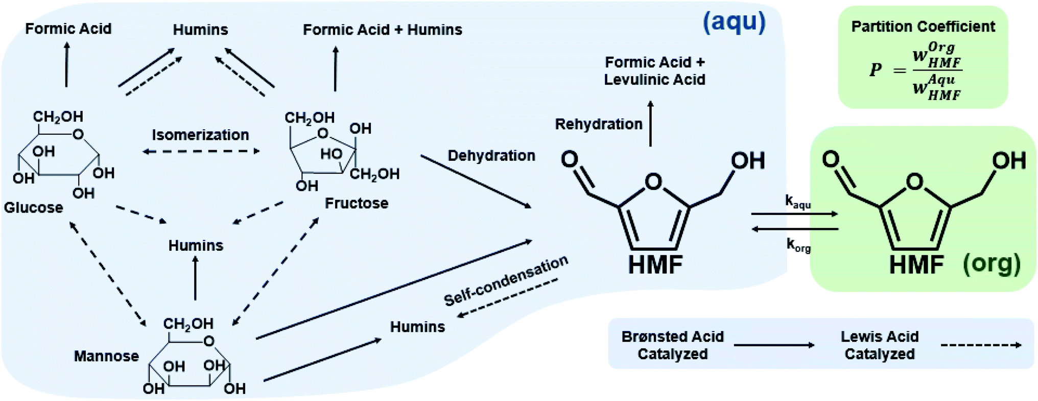 | ||
| Scheme 1 Reaction pathways of sugar chemistry in the aqueous phase (blue shaded area) and partition of HMF in an organic phase (green shaded area) in biphasic systems. Single-phase (blue shading) processing is feasible. | ||
Single aqueous phase reactions. Most batch fructose dehydration reactions have been performed at <150 °C and long reaction times. Yet, there are two reasons why one should carry this chemistry at higher temperatures. First, the activation energy for HMF formation is ∼142 kJ mol−1 over zeolite beta116 and ∼126 kJ mol−1 using HCl;42 those for HMF side reactions are generally <100 kJ mol−1,42 depending on catalyst. Thus, higher temperatures improve HMF selectivity. Second, the fructose mutarotation favors furanose over pyranose (Scheme 2), the active form from which dehydration occurs, enhancing the HMF rate due to having a higher concentration of the reactant's active structure.117 These facts underscore that high temperatures and low residence times, unattainable in batch reactors but accessible in continuous flow reactors, should be exploited. The examples discussed below demonstrate this hypothesis.
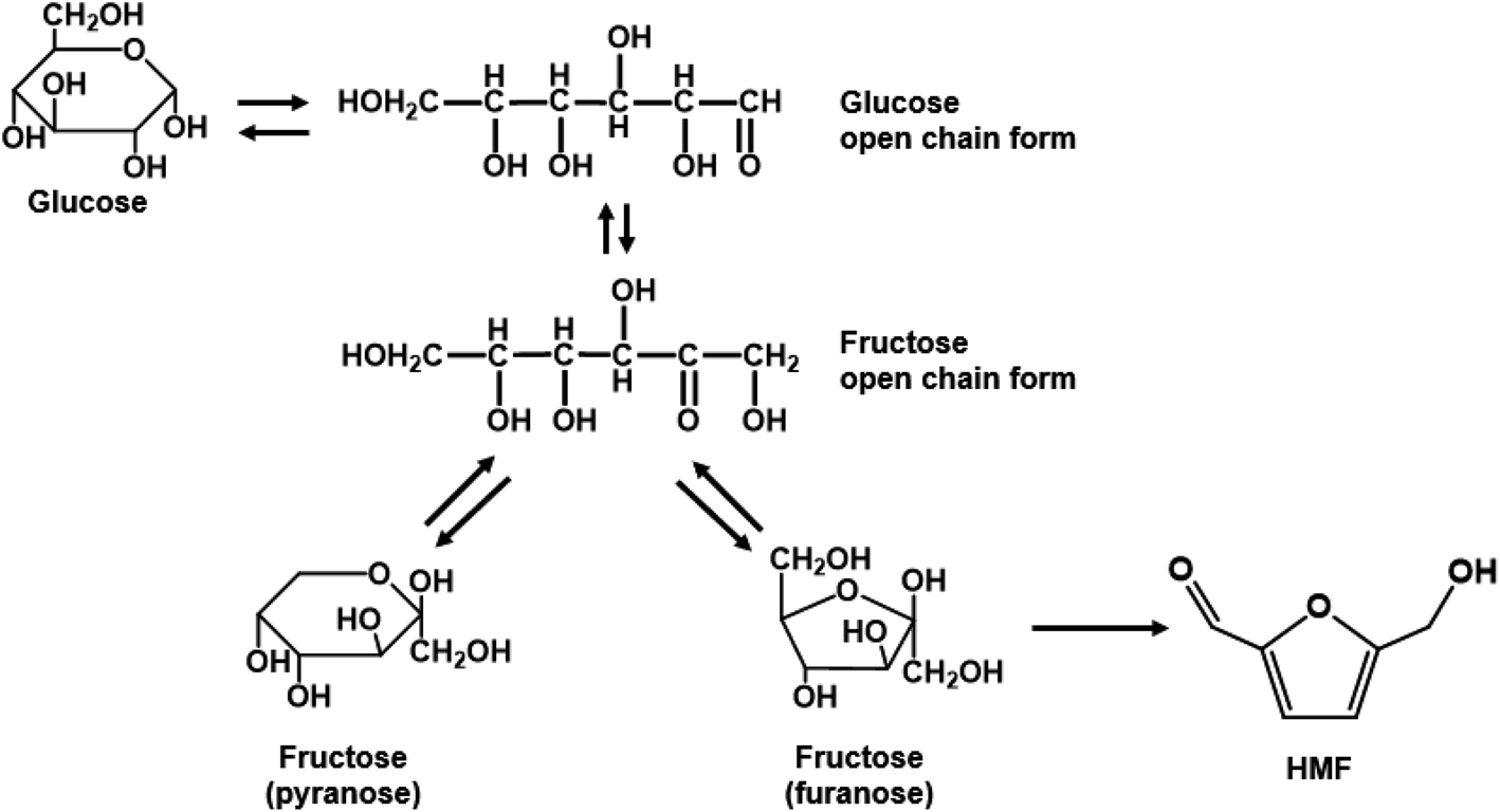 | ||
| Scheme 2 Glucose isomerization and fructose mutarotation in solution. | ||
Tarabanko et al. reported early on fructose dehydration in a microreactor using an H3PO4 catalyst at 240 °C.118 The highest HMF yield reported was 40% at a residence time of τ = 3 min.118 Tuercke et al. showcased continuous fructose dehydration at 185 °C, 17 bar, and 0.1 M HCl, reaching a fructose conversion of 71% and an HMF selectivity of 75% at τ = 1 min,119 surpassing the best batch data.52 The microreactor diameter of 1.2 mm provided a large surface area for heat transfer (∼1880 m2 m−3) to reach reaction temperature at short times. Beyond rapid heating, a significant advantage for continuous systems is that production is uninterrupted. In this regard, Schon et al. compared a microreactor and a microwave (MW) heated semi-continuous batch reactor.120 In a cartridge-based microreactor with HCl catalyst and conventional heating, HMF yields of 85.5% and 90.3% were obtained at 150 and 180 °C, respectively, at τ ∼ 3 min. On the other hand, while MWs' heating time to 200 °C is only 2 min, the productivity of the continuous reaction was 3× higher (2.07 vs. 0.72 g h−1), as the semi-continuous process spends 60% of its cycle time on pause, heating, and cooling stages. In passing, the reported yields are much higher (outliers) than all other studies and the theoretical maximum discussed below; they deserve attention but are not further discussed. For single aqueous phase reaction, Desir et al. reported the highest fractional HMF yield per time, achieving 54% HMF yield at τ = 4 s with HCl (pH = 0.7) at 200 °C.28
Single phase with co-solvents. Non-aqueous solvents often enhance HMF production due to the favored mutarotation of fructose to furanose. For example, in DMSO, the furanose increases from 20% to 72.3% at room temperature121–123 to 89.4% at 150 °C.121 It is no surprise that DMSO is often used as a co-solvent or solvent.52,124 Ly et al. described a single-phase DMSO continuous system utilizing Brønsted acidic imidazolium-based ionic liquid ([BMIMSO3H][HSO4]) catalyst giving a 46% HMF yield at 130 °C.125 However, DMSO is a “yellow” solvent due to its high boiling point and poor incineration score.126 Other organic solvents, such as acetone (greener on the solvent selection scale126), also improve HMF yield due to the mutarotation enhancement. Bicker et al. used a 10 mM H2SO4 in a pipe-in-pipe continuous, high-pressure system with 90
![[thin space (1/6-em)]](https://www.rsc.org/images/entities/char_2009.gif) :10 acetone:water solvent under supercritical conditions, improving the HMF yield >2× and productivity >27× compared to the aqueous system at τ = 1 min (99% fructose conversion and 77% HMF selectivity) at 180 °C.127 NMR experiments indicate an increased furanose:pyranose ratio of fructose in acetone (48:52 at 25 °C).123 The furanose is similarly favored in other environmentally acceptable solvents, such as methanol and acetic acid.123 However, supercritical operation imposes challenges for large-scale production. Yet, low boiling point solvents, like acetone, are good for downstream separation.
:10 acetone:water solvent under supercritical conditions, improving the HMF yield >2× and productivity >27× compared to the aqueous system at τ = 1 min (99% fructose conversion and 77% HMF selectivity) at 180 °C.127 NMR experiments indicate an increased furanose:pyranose ratio of fructose in acetone (48:52 at 25 °C).123 The furanose is similarly favored in other environmentally acceptable solvents, such as methanol and acetic acid.123 However, supercritical operation imposes challenges for large-scale production. Yet, low boiling point solvents, like acetone, are good for downstream separation.
Biphasic systems. A biphasic system involves an aqueous phase to carry out the reaction and an organic solvent (e.g., 2-butanol or MIBK) for HMF extraction to prevent HMF degradation. Extraction efficiency primarily depends on the partition coefficient of the different solvents.128 The most commonly used extraction solvents, 2-butanol and MIBK, are green and yellow,129,130 respectively. Toluene and THF have also been used, although alternatives, such as 2-methyl tetrahydrofuran,130 could be used (P3). Extractions are also mass transfer dependent. In batch, the two phases are vertically separated by solvent density, and stirring has limiting impact in the vertical space. On the other hand, microreactors give a high mass transfer and interfacial area and enhance extraction efficiency. HMF conversion and selectivity increase from the single-phase in batch to >70% in biphasic batch systems23,52,53 to >90% (ref. 23, 24, 131 and 132) in continuous biphasic systems, employing various flow patterns that promote internal circulation and transport between phases (Fig. 3 and 4). Specifically, Fig. 4 showcases the HMF extraction efficiency with its concentration profile under different slug lengths and parallel flow patterns.
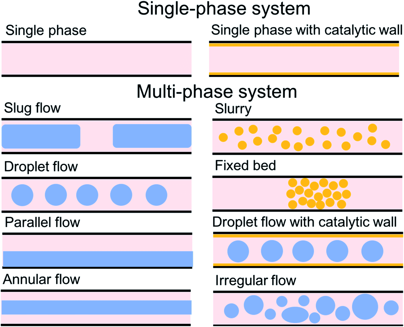 | ||
| Fig. 3 Flow patterns in microreactors. | ||
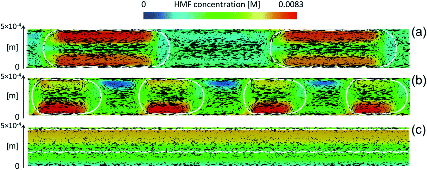 | ||
| Fig. 4 Characteristic mass transfer processes in different microflows such as (a) slug flow, (b) droplet flow, and (c) annular flow. Reprinted from ref. 48 Copyright (2021), with permission from ACS Publications. | ||
Tuercke et al. reported that the 53.3% HMF yield in a single-phase continuous system increases to 82% at 185 °C (17 bar, τ = 1 min) in 80:20 wt% water:DMSO and MIBK/2-butanol as the extraction solvent.119 Lueckgen et al.133 showcased that increasing the MIBK to water ratio from 0 to 4 at a constant residence time increases the HMF yield from <40 to 90%, and then reaches a plateau. The partition coefficient of HMF in 0.25 M HCl at 150 °C into MIBK was a modest 2.2 ± 0.4. An optimal HMF yield >80% was achieved in <40 s at 150 °C with a MIBK/aqueous ratio of 4, and an HMF productivity increased by >1 order of magnitude. On the other hand, while most studies used co-current flow, a few theoretical studies have studied countercurrent extractions to improve HMF removal.134,135 On this front, Roquette Freres patented a counter current process producing HMF at 80 °C using DMSO as the reaction medium to promote favorable mutarotation and MIBK as the extracting solvent. The HMF yield of 97.5% is one of the highest reported.136 Microdispersion technologies (i.e., microporous membrane) can also be incorporated into biphasic processes to promote extraction. Typically, biphasic systems employ a slug flow pattern, whereas membrane extraction utilizes dripping flow to create droplets on the membrane; the increased surface area further improves extraction efficiency. Additionally, commercial membranes are often inexpensive and can provide low Hagen–Poiseuille resistance due to the thinness of the material. Zhou et al. demonstrate an in situ membrane dispersion microreactor with 93% HMF yield at an organic to water ratio of 2.137 The typical organic to aqueous ratio for HMF extraction is 3–5, as the extraction efficiency plateaus at higher organic ratios, as mentioned above.119,132 Still, an additional phase separation agent could reduce solvent usage.
For tandem catalysis, Muranaka et al. described both glucose and fructose dehydration in a microreactor using phosphate buffer saline as the reaction phase and 2-sec-butyl phenol (2BP) as the extraction phase.23 While the highest HMF yield from glucose was 75.7 mol% at 180 °C, the long reaction time (47 min) marks a much lower HMF productivity. Guo et al. demonstrated a biphasic slug flow capillary microreactor with AlCl3 and HCl (pH = 1.5) and MIBK as the extracting solvent (4org:1aqu), yielding 53% HMF in τ = 16 min at 160 °C.25 The HMF yield further increased to 66.2% via salting out by adding 20 wt% NaCl. The reaction rate was doubled in the microreactor due to fast heating. As expected, tandem catalysis is generally 5–10× slower than direct fructose dehydration; otherwise, the biphasic extraction and microreactor enhancement effects parallel those in fructose dehydration.
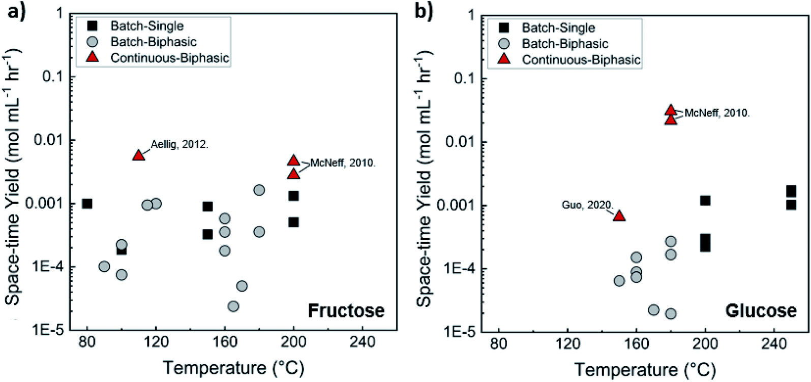
Comparison of batch and continuous flow homogeneous microreactors. The sugar conversion and HMF space-time yields in batch and continuous flow microreactors were surveyed. The results are plotted in Fig. 5a and c. There is more published data for fructose than glucose conversion. For fructose dehydration, HCl gives the highest activity for fructose dehydration among the homogeneous catalysts.119,132,133 This is due to the stronger dissociation of HCl that increases the concentration of protons and reactivity. Simulations of single-phase fructose dehydration as a function of pH and residence time, using kinetic parameters from Swift et al.,42 showcase the interplay between the residence time τ and pH; the lower the pH, the higher the rate, and the shorter the residence time for highest HMF yield (Fig. 5b). Decreasing the residence time translates to increased productivity. The variation of 3–4 orders of magnitude in productivity between different catalysts, such as phosphoric acid (a weaker acid), can be explained by this acidity effect. Similarly, tandem catalysis with HCl provides higher performance due to the fast fructose dehydration, and glucose isomerization is not rate-limiting (Fig. 5c25). Furthermore, as temperature increases, productivity increases in general. Experimental and simulated results at 180 and 200 °C are overlaid in Fig. 5b and d, and this τ–pH correlation explains most of the scatter in the vertical direction of Fig. 5a. Temperature and pH can be tuned in both batch and continuous systems. However, the ultrafast residence times (seconds) can only be exploited in the continuous system, as heating time is limiting for batch. This phenomenon showcases the situation where a careful design of the reactor geometry stretches the operating window, opening up the previously inaccessible regime to enhance product yields.
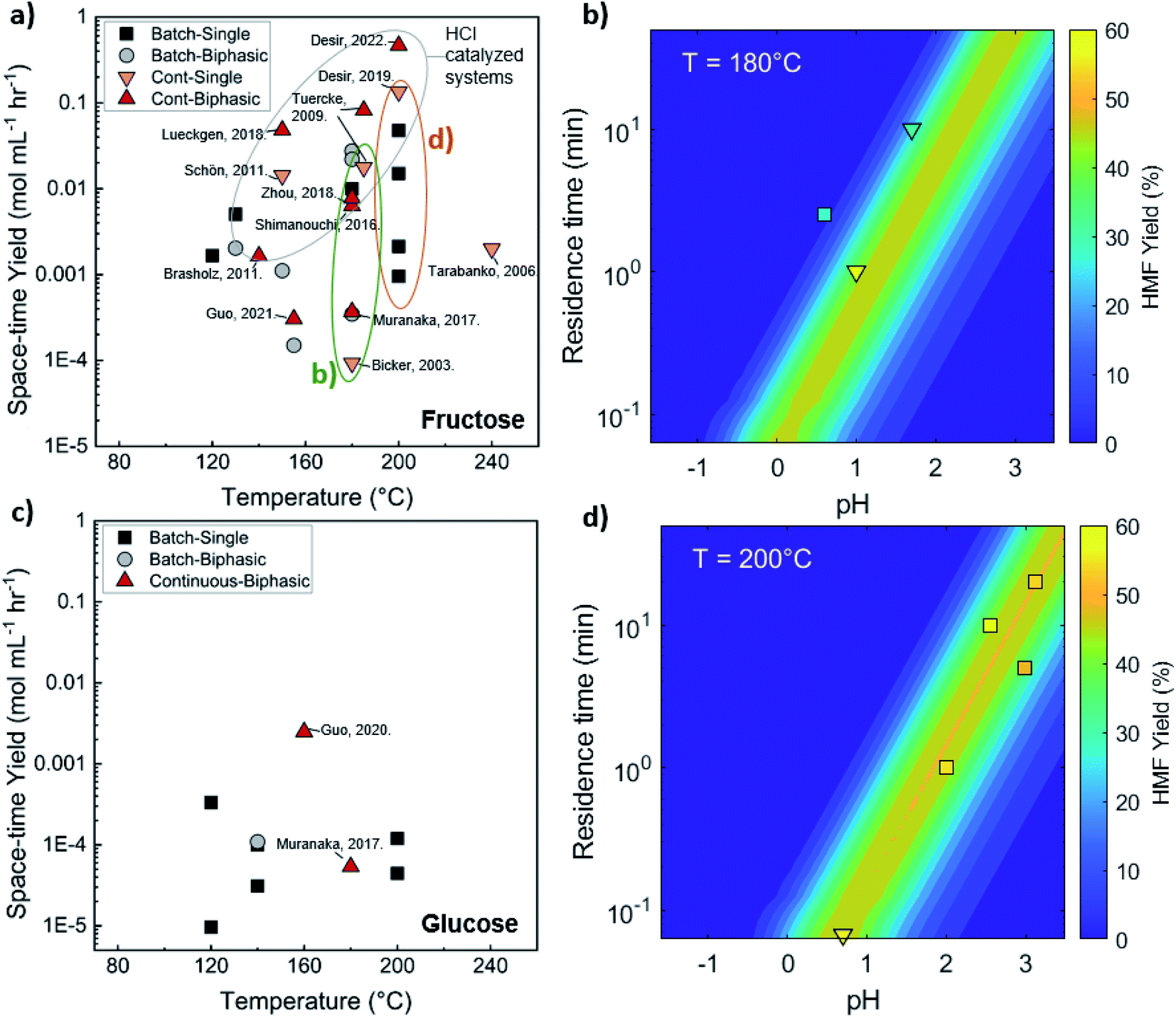 | ||
| Fig. 5 Experimental productivity of HMF in batch and continuous flow homogeneous phase microreactors in representative literature for (a) fructose and (c) tandem glucose dehydration reactions. Productivity variation among catalysts is attributed mainly to pH differences, with longer residence times and lower productivity for weak catalysts, such as phosphoric acid, and higher pH values. Predicted HMF yields at (b) 180 C and (d) 200 C in single-phase homogeneous reactions using the model of Swift et al.,42 with literature values overlaid. Data and experimental conditions are summarized in Tables S1 and S2.† Referenced works correspond to literature as follows: fructose: batch single-phase reactions,52,138–141 batch biphasic reactions,23,52,53,140,142 continuous single-phase reactions,28,118–120,127 and continuous biphasic reactions.23,24,53,119,132,133,137,143 Glucose: batch single-phase reaction,51,140,141,144–146 batch biphasic reaction,51 and continuous biphasic reactions.23,25 | ||
Biphasic systems exhibit overall better yield and productivity than single-phase systems due to favorable furanose mutarotation and increased HMF stability. There is a clear order of magnitude increase in productivity using microreactors – particularly continuous biphasic reactors – due to the large surface contact area, enhanced mass transfer, and rapid heating. The extraction efficiency depends on the partition coefficient and flow pattern. The formal is solvent and temperature-dependent, while the latter is tuned with reactor design and optimization of experimental conditions. Desir et al. showcased different flow patterns (droplet, slug, parallel, annular, and irregular) as flow rates and organic (MIBK) to aqueous ratios varied in the HCl-catalyzed biphasic dehydration reactions.47 Unlike most previous studies on slug flow, the irregular flow pattern gave the highest extraction efficiency of ∼97%, and thus, the highest HMF yield.132 As shown in Fig. 6a, temperature and residence time effects are transcribed into dimensionless Damköhler numbers and plotted against optimal extraction efficiency and HMF yields. A biphasic system can be operated under a kinetic-controlled flow regime utilizing irregular flow, giving an optimal yield is ∼60%. Higher experimental HMF yields have been reported by Desir et al. and in literature,24,119 where additional solvent effects on the reaction itself were hypothesized. Regardless, the extraction effect should be consistent. Furthermore, the actual productivity for a batch reactor is likely >60% lower120 as we did not include time for cleaning, refilling, heating, and cooling the reaction medium. In contrast, continuous systems operate non-stop for extended periods. Finally, co-solvents or organic solvents in biphasic systems may affect reactivity.132 It is important to note that the cost of hexose sugars is the highest contributor to the final HMF market selling price.147 Thus, maximizing the HMF yield in continuous biphasic systems (>90% HMF yield) is crucial (Fig. 7). As mentioned in the introduction of this section, reactions at high temperatures happen at short times. Thus, the batch data in Fig. 5 and 7 does not correspond to isothermal conditions, in contrast to the impression these and subsequent graphs give. Yet, the yield vs. conversion data in the single-phase fructose chemistry falls in a universal curve, and the lack of isothermal conditions makes a slight difference for this chemistry. Still, the biphasic continuous microreactor setup marries the advantageous short residence time with the stabilizing organic solvent, leading to >90% HMF yield that led to >10% HMF yield improvement from the biphasic batch system.
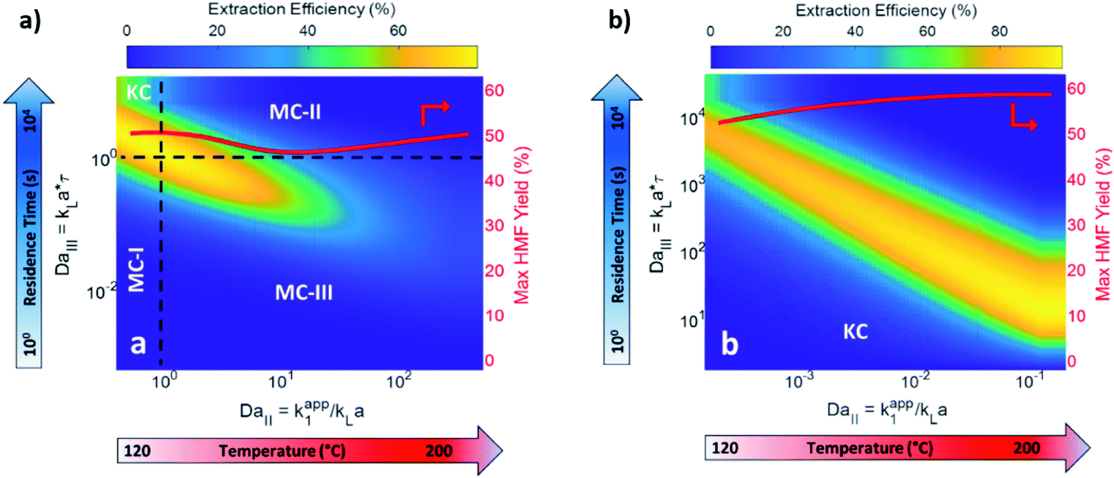 | ||
| Fig. 6 Predicted biphasic extraction efficiency and HMF yield in a microreactor as a function of Damköhler numbers in (a) biphasic irregular flow microreactor and (b) kinetic-controlled (KC) flow regime. KC and mass transfer-controlled (MC) regimes are delineated across the colormap. The two Damköhler numbers represent temperature and residence time effects. MC-I: mass transport is slow. MC-II: fructose dehydration rate > extraction rate. MC-III: fructose dehydration & contact time > HMF extraction rate. The solvents are MIBK and water, with HCl catalyst at pH = 0.7. Adapted with permission from Chemical Engineering Journal.132 | ||
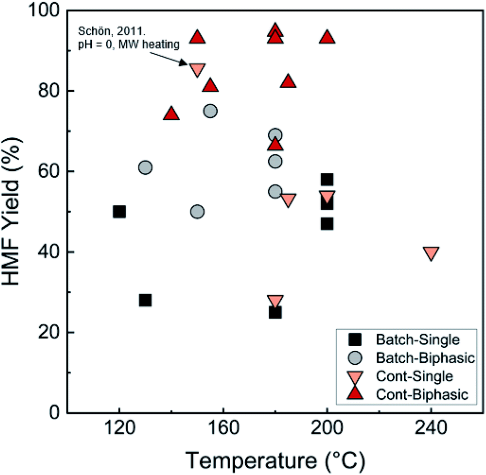 | ||
| Fig. 7 Comparison of HMF yields in single and biphasic batch and continuous flow microreactors in representative literature for the fructose dehydration reaction. The single-phase reaction with 85.6% HMF yield reported by Schön et al. with pH = 0 and MW heating120 is an outlier. Data and experimental conditions are summarized in Tables S1 and S2.† Referenced works correspond to literature as follows: fructose: batch single-phase reactions,52,138–141 batch biphasic reactions,23,52,53,140,142 continuous single-phase reactions,28,118–120,127 and continuous biphasic reactions.23,24,53,119,132,133,137,143 | ||
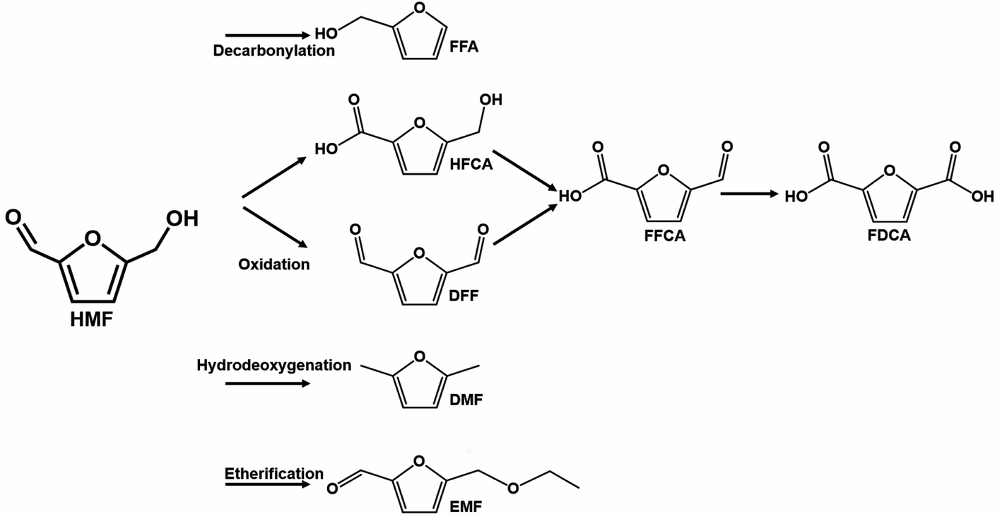 | ||
| Scheme 3 Downstream reaction pathways using HMF as a reactant. Compounds acronyms: furfuryl alcohol (FFA), 5-hydroxymethyl-2-furancarboxylic acid (HFCA), 2,5-diformylfuran (DFF), 5-formyl furan carboxylic acid (FFCA), 2,5-furan dicarboxylic acid (FDCA), 2,5-dimethylfuran (DMF), and 5-ethoxymethylfurfural (EMF). | ||
3.2 Heterogeneous catalytic reactors
Heterogeneous catalysts are industrially preferred over homogeneous ones due to easier catalyst separation and regeneration and reduced environmental footprint. However, solid catalysts in microreactors can lead to channeling and a large pressure drop. These problems can be circumvented using washcoats or larger reactor diameters. There are additional challenges for heterogeneous catalytic reactors, some specific to biomass. These entail (1) significant catalyst deactivation, which occurs at a fast rate given the high functionalization and reactivity of biomass derivatives; (2) catalyst leaching, which happens due to using solvents and non-neutral media; (3) lack of suitable commercial catalysts. Instead, novel catalysts need to be synthesized, and activation and characterization procedures need to be developed; and (4) lack of knowledge of deactivation mechanisms and regeneration protocols, topics not studied systematically. For demonstration, fructose dehydration using heterogeneous catalysts is reviewed here.:1 water:n-BuOH extraction at 200 °C at τ = 3 min.153 Despite the low HMF yield, the short contact time and high fructose concentration (23%) mark high productivity. An HMF yield of 29% was obtained at 180 °C at τ = 2 min and was further increased to 37% by adding 0.15 M HCl co-catalyst127 using a larger organic solvent usage (1:10 water:MIBK) instead of the 1:1 water:n-BuOH. MIBK is also known to be a superior extracting solvent. Up to 35% HMF yield was obtained from cellulose in the same setup at 270 °C with τ = 2 min and MIBK extraction.
For tandem Brønsted and Lewis acid catalysis starting from glucose, the focus has been on controlling the relative abundance and strength of Brønsted and Lewis acid sites. Engineering the catalyst is essential. Guo et al. showcased that the structure, acidity, and performance of P–TiO2 strongly depend on the synthesis.128 An optimum ratio of Brønsted to Lewis acid sites of ∼0.5 was discovered by adjusting the phosphate loading. At 150 °C, 73% HMF yield and >95% glucose conversion were obtained in 90 min.
The HMF space-time yield in batch and continuous flow microreactors is shown in Fig. 8. Compared to homogeneous reactors, the productivities are at least one order of magnitude lower. Again, there is significant variation in productivity at similar temperatures, but the reasons remain unclear. The catalyst amount and the strength and acid site density of catalysts are obvious reasons. Normalizing the data with the catalyst site density would reveal information on the acid site strength.
 | ||
| Fig. 8 Experimental productivity of HMF in batch and continuous flow heterogeneous phase microreactors in representative literature for (a) fructose and (b) tandem glucose to fructose to HMF reactions. Data and experimental conditions are summarized in Tables S1 and S2.† Referenced works correspond to literature as follows: fructose: batch single-phase reaction,141,145,155–158 batch biphasic reactions,131,159–167 and continuous biphasic reactions.131,153 Glucose: batch single-phase reaction,141,145,168–172 batch biphasic reactions,135,140,144–146 and continuous biphasic reactions.153,154 | ||
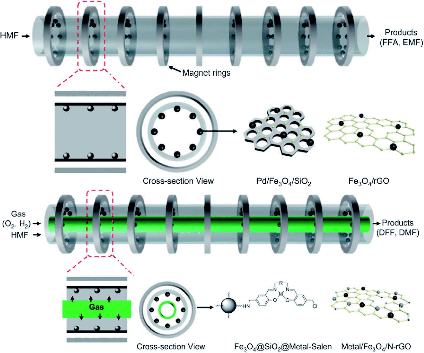 | ||
| Fig. 9 Illustrative scheme of binary and ternary-phase reactions for converting HMF into FFA, EMF, DFF, and DMF. Adapted from NPG Asia Materials152 (CC BY 4.0). | ||
3.3 Performance comparison of batch reactors and continuous flow microreactors
In this review section, we showed that the reactor geometry can significantly affect performance, which has been overlooked until now. Some general trends are obvious in the data. The fructose dehydration reaction with HCl catalyst is showcased here to summarize the benefits of microreactors. For a single-phase reaction, three crucial optimization parameters include temperature, residence time, and pH. Predictions using the kinetic model by Swift et al.42 show the interplay between variables (Fig. 5b and d). High HMF yield is obtained at high temperature and Brønsted acidity (lower pH). At relatively strong acidity, the higher HMF yield is achievable at temperatures >160 °C, where τ ≪ 1 min. The higher the temperature, the higher the yield. At sufficiently high temperatures, the yield is high over a range of pH values. The reaction time decreases profoundly by reducing the pH, i.e., by increasing the catalyst amount. These short reaction times are unachievable in batch systems due to heating constraints but are accessible at high temperatures and high catalyst concentration in flow systems. Due to the kinetics of the main and side reactions being first order in catalyst concentration, the selectivity is controlled by the temperature. In contrast, the catalyst amount affects only the processing time. This allows easy optimization of the yield and reactor volume.For biphasic systems, similar conclusions of high temperature and low τ leading to enhanced extraction efficiency, superior HMF yield, and high productivity are only achievable in continuous microreactors. The flow patterns affect the volumetric mass transfer and extraction efficiency. The highest HMF yield (94.7%) reported to date is in a biphasic system at 180 °C with pH = 1.6.24 Lowering the pH allows operation at lower temperatures,117 leading to an interesting tradeoff between utility cost for heating and capital cost for acid-resistant materials. While fewer studies have been conducted using heterogeneous catalysts, the evidence still points to a similar conclusion that enhanced mass transfer between the solid–liquid phases and reduced residence time led to increased HMF yields.
3.4 Outlook for microtechnology for biomass upgrading
Microreactors increase productivity at least >10× due to the increased mass and heat transfer rates, higher temperatures and shorter residence times, and minimal downtime. This field has vast opportunities for 3D printing or coating technologies to construct reactors, dowels, and catalysts deployment strategies (washcoats) and minimize pressure drop. HCl gives one of the highest HMF productivities for single-phase homogeneous fructose dehydration reported thus far. However, it is a strong acid with environmental and health concerns. It could compromise structural integrity due to corrosion at high temperatures and extended operations and increase capital costs by needing acid-resistant materials. Biphasic extraction at microscales improves yields due to enhanced heat and mass transfer and large surface areas. The compatibility of the reactor material hydrophilicity with solvents can affect flow patterns and transport. Engineering the material wettability, MW transparency, burst pressure rating, and visualization are essential for future work. Last but not least, microseparators utilizing specialized membranes can enhance separation while decreasing organic solvent usage.A rarely explored advantage of continuous flow systems is the extraction of intrinsic reaction kinetics and networks. These are unattainable in batch reactors, especially for ultrafast reactions and high temperatures. Yet, only limited studies have focused on the kinetics of renewable substrates in microsystems.42,123,127 Kinetics is vital in developing robust models for microreactor design and optimization using CFD.
Solid catalyst stability and reusability are vital. In most prior research, catalyst stability is assessed in batch systems, where catalysts are washed and reused after high conversion runs. Such an approach masks catalyst deactivation due to having catalyst excess, leads to catalyst loss during washing and transfer, and does not provide deactivation kinetics. Continuous operation enables estimation of the deactivation rate and, combined with catalyst characterization, can assist in developing regeneration strategies. We believe this is an area that needs significant attention for practical implementation.
4 Electrified microfluidic devices
As discussed in the previous section, microreactors demonstrate excellent potential for sustainable manufacturing by enabling the utilization of renewable, remote, and distributed feedstocks and enhancing transport rates by 2–3 orders of magnitude compared to conventional processes. However, process intensification and waste streams valorization are inadequate alone to transform manufacturing into zero emissions. Electrification is a vital pillar of this goal. It can employ renewable electricity to minimize CO2 emissions. Notably, it can provide unique advantages. For example, microwaves (MWs) can minimize side reactions, decrease processing times, and enhance energy efficiency, whereas plasmas can operate far from equilibrium, overcome thermodynamic limitations, and activate stable molecules. These traits, combined with the continuous microflow technology, create exciting prospects for sustainable manufacturing. This section summarizes the current progress in the emerging field of integrating microreactors with microwaves and plasmas using alternative energy sources. We leave out other electrified systems, such as sonication, inductive heating, and electrochemical devices.4.1 Electrification using microwaves (MWs)
Synthetic MW chemistry was born in 1986 with publications featuring stark rate enhancements in kitchen-grade MW ovens.173,174 As the technology matured into commercially available mainstays,175,176 the field has grown with more than 2000 publications every year.177 Aside from rate enhancement, MWs pave the way for sustainable chemical manufacturing. Principally, MW-based process electrification enables the sourcing of energy from renewable resources, such as wind or solar (P7). Further, MW heating is driven by dipole polarization and ionic conduction, and the energy is deposited directly and volumetrically instead of relying on conventional slow conduction and convection. This direct coupling underscores rapid and selective heating that can improve energy efficiency (P6), reaction rate, and selectivity.178 Selectivity improvement is associated with lower energy use in separations, and for renewable feedstocks, selectivity and conversion determine the carbon efficiency conversion and the economic viability of a process. The inherent safety from the direct energy coupling with the reaction mixture179,180 (P12) and the compatibility of MWs with catalysts (P9) make process electrification a fertile technological ground for sustainable chemical manufacturing.Here we focus first on the enhancements actuated by MWs, which are unachievable by conventional heating. These so-called “MW-specific” effects are often purported to improve rate, yield, and/or selectivity and are almost always related to the selective nature of MW heating. Then, we describe MW technology and efficiency at a macroscopic level and its integration with the microflow technology.
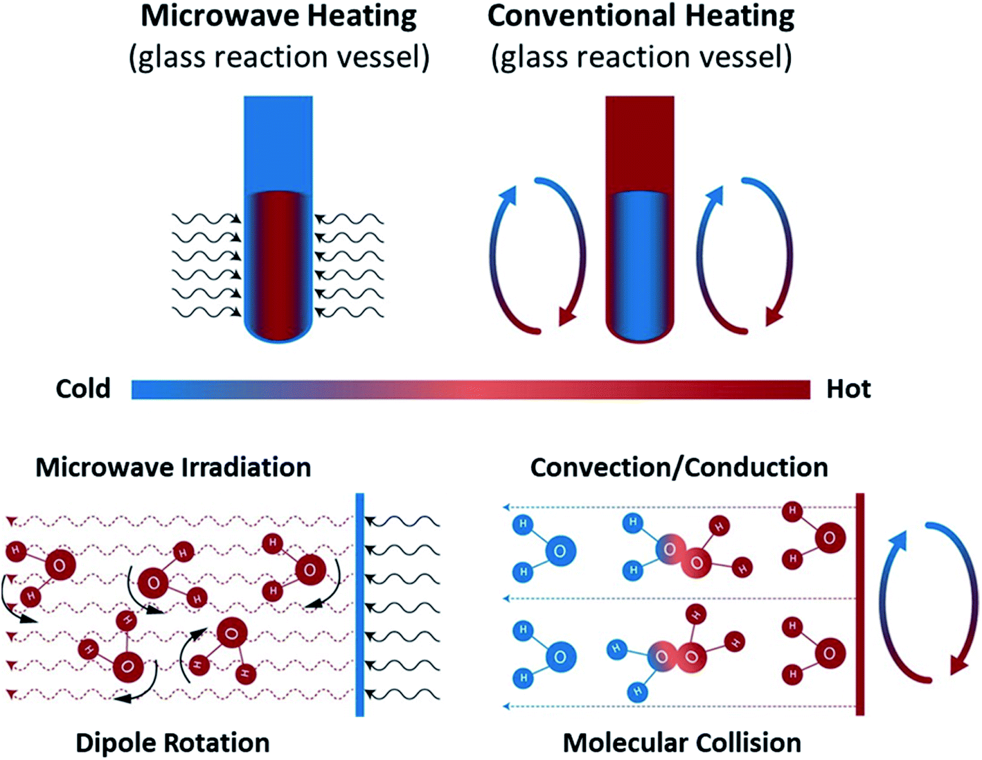 | ||
| Fig. 10 Microwave and conventional heating modes. Recreated from ref. 181 (CC BY 4.0). | ||
MW-specific effects, especially those in single-phase liquid systems, have been hotly contested over the years. They are critical to understanding the reported observations and the potential of MWs for chemical manufacturing. In our opinion, the most plausible and well-documented effects (of those that impact chemical systems) pertain to bulk superheating and local overheating.
Bulk superheating. One of the earliest-recognized173,174 and more-substantial aberrancies of MW heating is MW-induced superheating. While difficult to quantify, due to a lack of MW-appropriate thermometric methods, Baghurst and Mingos surveyed MW heating of various solvents using temperature-sensing, MW-transparent optical fibers.182 Chemat and Esveld later concluded that the MW superheating effect is driven by the inverted temperature gradients.183 Traditional nucleate boiling occurs at the solvent–container interface, where pits and scratches serve as nucleation points. For conventional heating (CH), heat is transferred into the liquid through this interface, and, therefore, the interface is warmer than the bulk liquid. For MW heating, however, the solvent–container interface is the coldest, thereby diminishing nucleation. In the absence of such interfaces, MW boiling occurs at the gas–solvent interface at the headspace. Superheating of up to 40 °C above conventional boiling points was reported. MW superheating was applied to the esterification of benzoic acid and the cyclization of citronellal, speeding reaction rates and creating kinetic zones only accessible to MWs for a given pressure. This effect of MW-exclusive temperature zones and the ensuing kinetic enhancement is demonstrated in Fig. 11. Rate enhancements of 1–2 orders of magnitude over CH were observed, and correlations were developed to predict the MW boiling point and ensuing rate enhancements for a library of solvents and reactions.
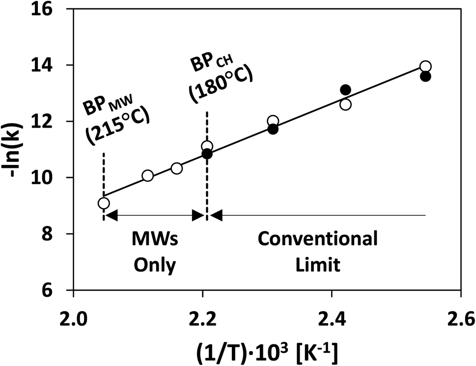 | ||
| Fig. 11 Rate constant of thermal cyclization of citronellal under conventional (solid circles) and MW heating (hollow circles). Redrawn from ref. 183 with permission from John Wiley and Sons (2022). BP = boiling point; MW = microwaves; CH = conventional heating. | ||
Cablewski et al. demonstrated MW superheating in a continuous flow, reaching temperatures up to 100 °C above the conventional boiling point for various volatile solvents, and rate enhancements of 2–3 orders of magnitude for a wide swath of reactions.180 While the authors did not rationalize this outsized superheating effect, it is perhaps not surprising that MW superheating in continuous flows might exceed batch behavior due to lack of headspace and a smooth borosilicate tubing (sometimes perfluoroalkoxy Teflon), reducing nucleation.
Aside from simply accelerating reactions, superheating improves selectivity and the use of less aggressive reagents or lower quantities of them.180 For example, in the production of methyl 2-phenylethyl ether from 2-(bromoethyl)-benzene, the byproduct (styrene) selectivity was decreased. In another case, the esterification of mesitylenecarboxylic acid was performed with small fractions of sulfuric acid (∼1.5%), compared to CH,184 involving 100% sulfuric acid. Polshettiwar and Varma proposed that MW superheating allows for greener solvent selection.185 Higher temperatures by MWs allow water – the greenest solvent available – to behave as a “pseudo-organic” solvent and enable the solvation of organic substrates without a phase-transfer catalyst. A large swath of organic synthesis reactions proceeds at high yields in the aqueous MW environment, including Suzuki186–188 and Heck189 coupling, nucleophilic substitution,187 and many others. Varma and coworkers have reviewed MW-assisted organic synthesis in aqueous media.190 Nucleation-friendly solids in MW-heated liquids (shown with boiling stones and optical fibers) diminish the superheating effect,183 likely isolating the MW superheating to systems without heterogeneous catalysts.
Local overheating. MW-heated single-phase reactions are often reported to far outperform CH at the same bulk temperature.178,181,191,192 Perreux and Loupy178 purport that enhancements may be due to a non-thermal MW effect. Dudley and coworkers192 suppose a MW-actuated thermal effect. Contentiously,192–195 the enhancement is often challenged in critical literature, and, in many cases, the effect is ascribed to inaccurate temperature measurements.193,196 Kappe and coworkers showed that IR thermometry often underestimates the temperature, leading to erroneous claims of enhanced rates. Therefore, great care must be taken in measuring temperature in MW systems.197,198 Standing atop of these efforts, the following corollary has emerged: When at the same temperature, reactions occur at the same rate under MW and conventional heat.199
Abiding this corollary – and taking note of local “hot spots” purported to occur throughout the bulk of MW-heated liquids191,200 – Keglevich and coworkers proposed that rate enhancements in homogeneous reaction mixtures could be linked to locally overheated zones in a statistical manner:201–203
 | (3) |
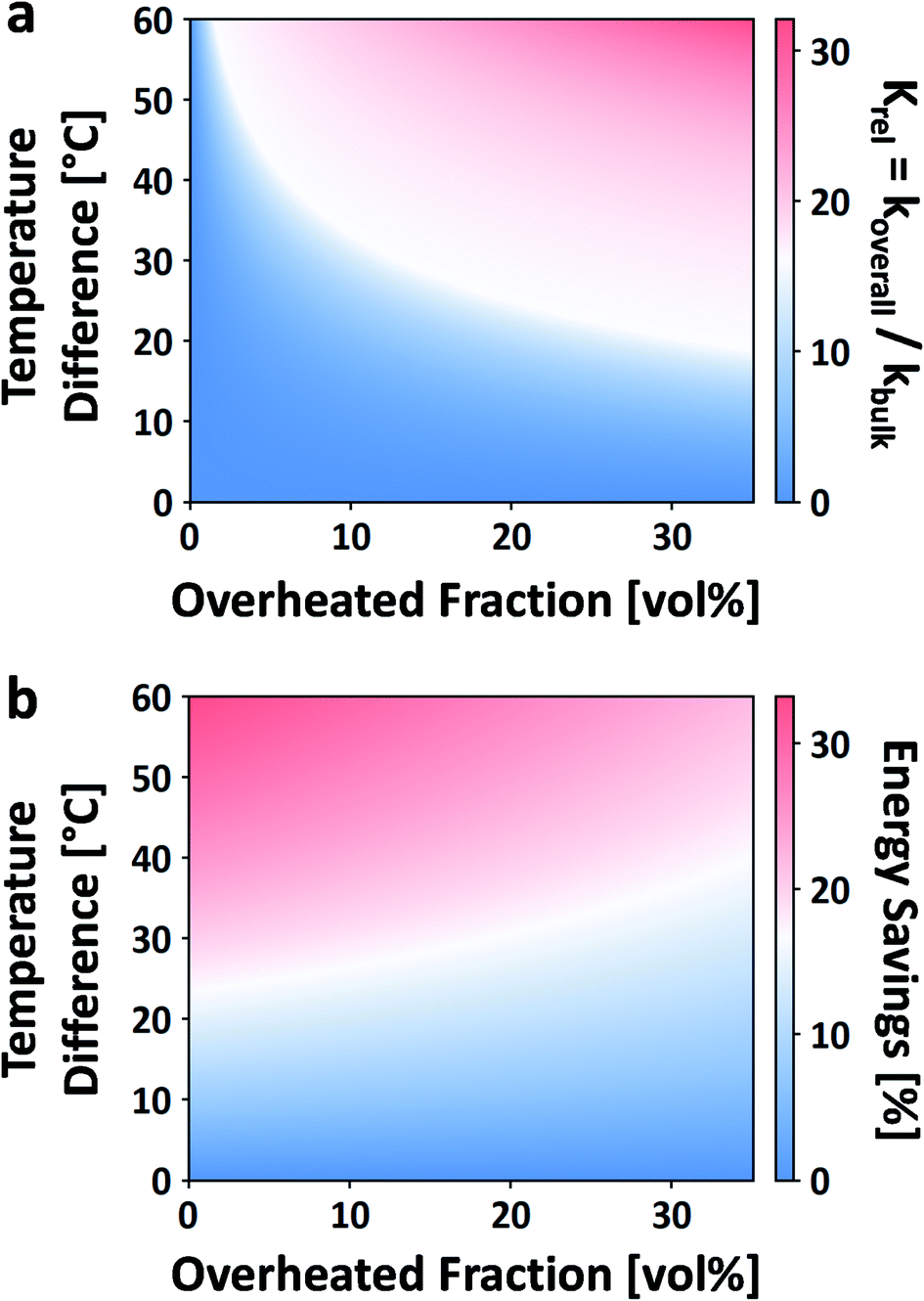 | ||
| Fig. 12 Effect of local overheating on the rate constant of acid-catalyzed fructose dehydration to HMF (a). Calorimetric energy savings due to the same local overheating and lower bulk temperature effect (b). For these calculations, reaction parameters taken from ref. 42, Tbulk is 150 °C, and an overheated zone of only a single non-bulk temperature is considered. | ||
While this framework resolves the impasse between observed rate enhancements, it does little to address what the size, temperature, or the number of overheated zones are. For example, Ricciardi et al. recently showed a 7–13× rate enhancement in the acid-catalyzed dehydration of xylose to furfural in aqueous media.204 Due to the inability to measure the overheating, they were left to fit the number, sizes, and temperatures of the overheated volumes based on the rate enhancements, making several assumptions. It was estimated that for a single overheated volume, VOH/VO is 5–20% and ΔT is ∼0–100 °C (despite the fact that ΔT scales with Tbulk).
Clearly, a better description of these overheated regions is required. Recently, Horikoshi and coworkers noted that the dielectric properties of polar/non-polar binary mixtures do not abide by ideal assumptions and can instead have strong excess properties at certain ratios.205 They also linked the excess dielectric properties and the Kirkwood g-factor – a thermodynamic quantity that estimates the magnitude of parallel polar alignment with its neighbors. Specifically, as the composition of a binary mixture is altered from one extreme to the other, it may cross the threshold of g = 1 (above which it is parallel and below antiparallel). The binary concentration at the crossing point also corresponds to the maximum/minimum excess dielectric behavior. They inferred a strong link between these properties and the microscale structural behavior (i.e., clustering) of polar and non-polar solvents. This phenomenon, in turn, aligns with the description of Keglevich and Mucsi that locally overheated regions should be well-distributed, nano-sized, and impractical to measure by conventional means.203
Dudley and coworkers have similarly theorized that overheated zones are owed to MW-absorbing solutes contained in MW-transparent solvents.192,206,207 They analyzed the MW-heating of p-nitroanisole (pNA; polar) in mesitylene (non-polar).208 Small-angle neutron scattering showed agglomerates of pNA of roughly attoliter-sized (10−18 L) spheres, while in situ Raman spectroscopy demonstrated that agglomerates heat up to 114 °C above the bulk under MW irradiation. The same group analyzed the kinetics of a Claisen rearrangement reaction in the same pNA/mesitylene system, where the reactant, allyl naphthyl ether (non-polar), partitions between the bulk and the agglomerates.209 3× rate enhancements were observed over that at the bulk temperature, constituting the first compelling evidence of MW-induced local overheating and rate enhancement.
Several questions remain regarding the MW local overheating. For example, the breadth of solvents with this microscale structural behavior is unclear. If indeed acidic aqueous solutions, such as those used in biomass processing, exhibit this clustering, why would this create local overheating given the already-polar nature of the bulk solvent? Furthermore, estimating the size of these structures is critical. While scattering methods are excellent, these methodologies are ill-suited for high-throughput solvent selection and screening. Molecular dynamics (MD) and other computations have shown such clustering in aqueous and other solutions, but to our knowledge, these methods have not yet been applied to the analysis of MW heating behavior.210,211
The enhanced reaction rates enable more compact processes while tempering the energy requirements. Under MW heating, the acid-catalyzed dehydration of xylose takes place not at the bulk temperature, but at overheated zones.204 In that particular study, the bulk temperature is 140 °C while the overheated zones are estimated to be ∼200 °C and the overheated fraction is estimated to be 5–20%. On a purely calorimetric basis, one can extend the analysis of Keglevich and coworkers203 to estimate the energy Qoverall required to heat such a system:
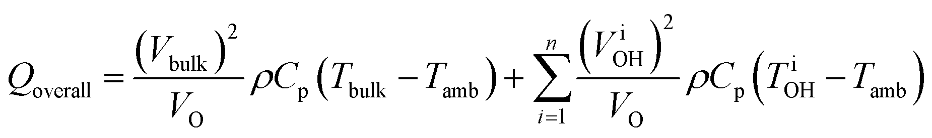 | (4) |
Liquid–liquid systems. In liquid–liquid biphasic systems, MWs result in selective heating of the polar aqueous phase than a non-absorbing organic phase, as illustrated in Fig. 13. Liquid–liquid biphasic systems are often employed for reactive extraction, including lignocellulosic biomass described in the previous section.
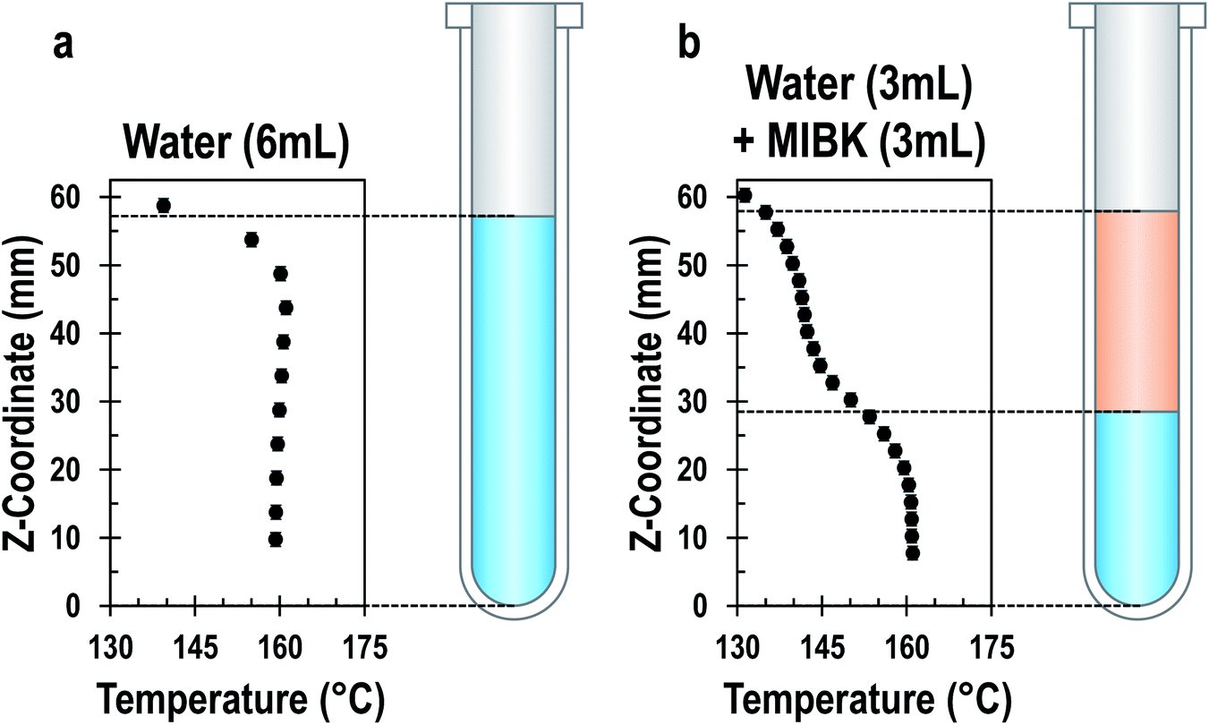 | ||
| Fig. 13 Temperature profile of aqueous single-phase system (a) and water/MIBK biphasic system (b) at steady state under MW irradiation. Both systems have a total volume of 6 ml and the biphasic system has a 1:1 phase ratio. Adapted with permission from ref. 212 Copyright (2022) American Chemical Society. | ||
While an organic phase extracts HMF or furfural in situ to enhance yield by removing the product from the reaction media to prevent side reactions,213 recent studies have shown that MWs can further boost performance, as shown in Table 3.214–217 For example, Breeden et al. showed that for 5-chloromethylfurfural (CMF) forming in a water/dichloroethane system, the yield increased from 75% to 85% and the selectivity from 96% to 98% over CH, while allowing the use of non-halogenated solvents like cyclohexane.185 Wrigstedt et al. report 91% yield and 92% selectivity to HMF in fructose dehydration in a (0.05 M HCl + KBr)(aq)–MeCN biphasic system in 1 min of heating at 160 °C; meanwhile, only 38% yield and 61% selectivity were achieved with CH in 10 min (optimized CH time yielded 79% at 84% selectivity).215
| Study | Reaction Conditions | Performance | |||
|---|---|---|---|---|---|
| Reactant & product | Catalyst & temperature | Extracting phase (Aq:Org) |
Conventional | Microwave | |
| Breeden et al.214 | Fructose, CMF | HCl, 80 °C | Dichloroethane (1:2) |
Y: 78% | Y: 85% |
| S: 96% | S: 98% | ||||
| Wrigstedt et al.215 | Fructose, HMF | HCl, 160 °C | Acetonitrile (1:2) |
Y: 79% | Y: 91% |
| S: 84% | S: 92% | ||||
| Yang et al.216 | Xylan, furfural | Al2(SO4)3, 130 °C | γ-Valerolactone (1:4) |
Y: 79% | Y: 89% |
| S: — | S: 98% | ||||
| Ricciardi et al.217 | Xylose, furfural | H2SO4, 200 °C | Toluene (1:1) |
Y: 65% | Y: 77% |
| S: 68% | S: 79% | ||||
Ricciardi and coworkers demonstrated using a small library of solvents that the MW-mediated boost in furfural yield correlates strongly with the MW-transparency of the organic phase (as estimated by the dielectric constant, ε′).217 It is posited that increasing the MW-transparency leads to a colder organic phase, increased extraction, and higher yield. However, none of the works offer temperature measurements of the organic phase or demonstrated that the increased yield is due to improved extraction. While plausible that a colder organic phase enhances extraction, no explanations address the increased rates.
Recently, we have analyzed MW-induced temperature gradients in liquid–liquid systems.212 It is found that the dielectric properties and the temperature gradient correlate strongly but that both the real and imaginary components are important. Additionally, the specific surface area, the ratio of the two phases, the heat transfer coefficient, and the intensity of power dissipation are important. A simple analytical model predicts the temperature gradient between phases:
 | (5) |
Aside from rate and selectivity enhancements, there are also energy savings in MW-heated biphasic systems. With similar assumptions to those made in (4), when the aqueous phase of a 1:1 water/MIBK system is at 160 °C, and the organic phase is 35 °C cooler (ΔT = 35 °C), the energy savings compared to CH would be about 7.8%. With 1:2 and 1:4 water/MIBK systems, the energy savings for the same ΔT would be 12.1% and 16.6%, respectively. Because ΔT drives several phenomena, optimizing these systems for a colder organic phase will likely improve yields, selectivity, and energy consumption.
Liquid–solid systems. MWs are compatible with liquid/solid heterogeneous systems, including slurries, fixed beds, and structured catalysts. Among these, batch-phase slurries have definitively enjoyed the most attention, as this mode is used by synthetic chemists for routine heterogeneous catalytic transformations. Suspended solids can include zeolites,218 resins,219 clays,220 carbons,221,222 metals,223 and metal oxides.224 Similarly, the liquid phase can be either polar218,222 or non-polar.221 Several recent reviews on sustainability are available.225,226 As in other areas of MW-assisted synthesis, large rate enhancements are often reported (see Table 4). However, this literature focuses mainly on the synthetic analysis with assuredness that the methodology is efficient and eco-friendly, and little attention to the MWs. Rarer are works attempting to analyze the specific roles of MWs and how to optimize them to enhance chemical processes further. We summarize select ones below.
| Reaction | Catalyst & conditions | Reactants & products | Solvent | Performance | Additional differentiation | |
|---|---|---|---|---|---|---|
| Conventional | Microwave | |||||
| Dehydrogenation231 | Pt/AC, 207 °C (120 min) | R: tetralin; P: naphthalene | Neat | X tetralin: 32% | X tetralin: 50% | |
| Dehydrogenation201 | Pt/carbon, 207 °C (90 min) | R: tetralin; P: naphthalene | Neat | Y Naph: 3.5% | Y Naph: 17% | Carbon: AC |
| Y Naph: 6% | Y Naph: 25% | Carbon: CMC | ||||
| Dehydrogenation232 | Pt/AC, 220 °C (120 min) | R: tetralin; P: naphthalene | Neat | X tetralin: 32% | X tetralin: 31% | No insulation |
| X tetralin: 56% | Dewar-like reactor | |||||
| Pt/AC, 220 °C (60 min) | X tetralin: N/A | X tetralin: 28% | Suspension state | |||
| X tetralin: 68% | Liquid film state | |||||
| Suzuki coupling221 | Pd/AC, 110 °C (120 min) | R: phenylboronic acid, 4-bromotoluene; P: 4-methylbiphenyl | Toluene | Y 4-mBP: 2.8% | Y 4-mBP: 11.8% | E-Field |
| Y 4-mBP: 22.1% | H-Field | |||||
| Suzuki coupling230 | Pd/carbon, 110 °C (150 min) | R: phenylboronic acid, 4-bromotoluene; P: 4-methylbiphenyl | Toluene | Y 4-mBP: 14% | Y 4-mBP: 23% | Carbon: AC |
| Y 4-mBP: 17% | Y 4-mBP: 38% | Carbon: CMC | ||||
| Suzuki coupling227 | Pd/CMC, 110 °C (80 min) | R: phenylboronic acid, 4-bromotoluene; P: 4-methylbiphenyl | Toluene | Y 4-mBP: 18.7% | Y 4-mBP: 10.2% | No MAHS |
| Y 4-mBP: 34.2% | With MAHS | |||||
| Suzuki coupling228 | Pd/CMC, 70 Watts (60 min) | R: phenylboronic acid, 4-bromotoluene; P: 4-methylbiphenyl | Toluene | Y 4-mBP: 21.3% | Y 4-mBP: 5.7% | E-Field |
| Y 4-mBP: 34% | H-Field | |||||
| Y biphenyl: 8.8% | Y biphenyl: 3.9% | E-Field | ||||
| Y biphenyl: 5.7% | H-Field | |||||
| Suzuki coupling222 | Pd/rGO, 80 °C (10 min) | R: phenylboronic acid, 4-bromobenzaldehyde; P: 4-phenylbenzaldehyde | Water + ethanol | — | Y 4-PhBAL: 100% | |
| Ullmann coupling223 | Cu (60 min) | R: potassium phenolate, 4-chloropyridine; P: 4-phenoxypyridine | Dimethyl-acetamide | Y PhPyr: 38% | Y PhPyr: 60% | 110 °C |
| Y PhPyr: 83% | Y PhPyr: 85% | 140 °C | ||||
| Hydrogenation224 | Cu/TiO2, 125 °C (120 min) | R: furfural; P: furfuryl alcohol | cylopentyl-methyl ether | Y FOH: 26% | Y FOH: 97% | |
| S FOH: 94% | S FOH: 99% | |||||
| Hydrolysis218 | H-Beta & HCl, 180 °C | R: microcrystalline cellulose; P: glucose, HMF, levulinic acid, formic acid | Water | X cellulose: 7% | — | 360 min |
| — | X cellulose: 12% | 60 min | ||||
Horikoshi and coworkers devoted considerable effort to understanding MW-heated slurries in batch systems, primarily in the Suzuki coupling221,227–230 and tetralin hydrogenation.231,232 The observed MW-mediated rate enhancements in the latter over a slurry of carbon-supported platinum was attributed to selective heating of the carbon.231 For the former reaction over carbon-supported palladium, the effect was sometimes enhancing221,230 and sometimes detrimental.227–229 Hot spots and arcing on the highly MW-absorbing carbons increase temperatures from 400 to 1400 °C,228,229 leading to catalyst sintering and deactivation.221 This sintering seemingly did not affect platinum catalysts as severely (possibly due to its higher melting point).230–232 This undesired behavior could be controlled by placing samples in locations of high H-field intensity (rather than E-field) to produce magnetic heating and reduce hotspots. MW-heating can lead to higher yields of the desired product – 4-methylbiphenyl – and lower selectivity to byproducts, like biphenyl, than CH.221,228
Morphologically controlled supports, such as carbon microcoils rather than activated carbon, decrease hot spots and enhance yields due to the lack of sharp edges for charge accumulation.230 In related work, Belecki, Gupton, and coworkers demonstrated strikingly fast rates for a similar reaction over palladium on graphene, reaching 100% yield in 10 min at a bulk temperature of only 80 °C.222 They attributed this to the electron withdrawing and donating groups and reported no arcing. Finally, insulation, MW receptors, or other means can decrease the temperature gradient between the solid and liquid phases to decrease deactivation and boost yields.227,229,232
Less MW-absorbing solids, such as zeolites, clays, and metal oxides, have also been employed in slurries. For example, Romano et al. employed copper nanoparticles supported on TiO2 for the hydrogenation of furfural.224 At otherwise identical conditions, furfuryl alcohol yields were >3× and selectivity was modestly boosted compared to CH. Similarly, for the tandem hydrolysis and dehydration of cellulose, a zeolite slurry with HCl heated via MWs gave 10× rate enhancement over CH.218 Solids like zeolites do not absorb MWs as aggressively as carbons and do not arc but still exhibit rate enhancements.
The phenomena in these multiphase systems (slurries) are linked directly to selective MW heating. Depending on the solid, the bulk liquid phase can be cooler than the liquid immediately surrounding the catalyst and the catalyst (if one exists). This effect is, presumably, responsible for the accelerated rates and boosted yields. However, the electric field enhancement near edges can result in Joule heating, hot spots, or even arcing. The overheating of the solid can cause catalyst sintering and deactivation. Recently, we have developed analytical expressions to predict the temperature gradients between liquid and solid in MW-heated slurries, like eqn (5), and criteria to avoid arcing.70 Clearly, there is a need for developing principles to optimize these systems.
While a fundamental picture of the MW-heated liquid–solid systems is emerging, more work is needed to understand their best applications. For example, design principles for packed beds or structured catalysts have not been developed. It is unclear how these systems may differ from slurries, especially regarding arcing and hotspots. Structured catalysts should reduce arcing due to their monolithic structure and uniform heating.233–235 Furthermore, unlike liquid–liquid systems, the measurement of solid temperatures is not straightforward. Finally, while elevated solid temperatures could certainly enhance rates, it has not been demonstrated that this is the sole reason for enhanced performance.
MW-heated continuous-flow reactors for single and multiple phases. Single-phase liquid systems are the most widespread, owing partly to commercially suitable MW applicators. Still, many customized designs have been demonstrated. A variety of chemistries have been demonstrated, including Claisen rearrangements,246–249 Suzuki coupling,186,187,246,250 Heck reactions,246 nucleophilic substitution,180,187,250 esterification,180,250,251 transesterification,252,253 and more. Quite often, reactions proceed very quickly. However, direct comparisons between MW-heated and CH flow reactors are difficult to make, often for reasons related to temperature measurement. For example, Organ and coworkers demonstrated a MW-heated capillary reactor built into a commercially available Biotage applicator.186,187 This applicator uses a pyrometer to measure temperature (and, if desired, provide feedback for power modulation). However, the spot size of the pyrometer may be ill-suited for the geometry, or the capillary wall temperature may not be representative of the internal temperature. As a result, temperature measurements are not discussed, and instead, the applied power was used as a proxy.
Hoz and coworkers coiled a capillary around a sizeable MW receptor (a Weflon bar) and measured the receptor temperature via a pyrometer.254 Using the single-point pyrometer measurement of the receptor as representative of the entire capillary, comparison was made to a CH system. A doubling in conversion was observed for the isoxazole synthesis reaction. Another approach entails inserting a thermocouple directly into the flowpath at the exit of the MW cavity assuming an isothermal reactor.180 However, MW-heated flow reactors are often non-isothermal, as demonstrated using thermal cameras246,255–257 or location-adjustable temperature-sensing optical fibers.212,258,259 Of the works that consider the axial temperature distribution, an occasional rate enhancement is reported,246 but the number of high-quality comparisons of this sort is limited. Despite the insufficient evidence for MW-specific rate enhancements, the rapid heating rates offered by MWs (often reported as more than 5 °C s−1; sometimes as high as 50 °C s−1) allow for high productivity.246,260
Relative to a single-phase, a few works exist for liquid–liquid212,261,262 or slurry180,219,220 flows (excluding nanoparticle synthesis). In the former, MW rate enhancement for tandem diazotization and Heck reactions was reported without an explanation.262 Selective heating and liquid–liquid temperature gradients have been demonstrated without focusing on reaction enhancements.212,261 In the slurry flow mode, Chemat and coworkers demonstrated an esterification rate enhancement of 50–150% and attributed that to selective heating of the solids (iron(II) sulfate adsorbed onto clay) calculated (but not measured) to be 9–18 °C above the bulk liquid temperature.220
MW-heated continuous flow packed beds occupy a more significant space in literature. Notably, a few have been made with carbon supports despite their problematic performance in slurries.263–265 Bo and coworkers employed a continuous flow system to mineralize p-nitrophenol using a fixed bed of activated carbon.263 This MW reactor far outperformed an electrical oven operated at approximately the same power (500–600 W) due to the bed reaching much higher temperatures of 500 °C than 98 °C in the electric oven. Later, the same group demonstrated that a platinum catalyst deposited onto the carbon not only was compatible with MWs, but further enhanced performance.264 Zhao et al. demonstrated the MW-assisted oxidation of HMF into FDCA over a Ru/C catalyst in a continuous flow,265 giving an optimized yield of 47% vs. 88% in batch mode. The low yields were attributed to the degradation of the catalyst microstructure due to humins formation. While hot spots surely arise in MW-heated carbon beds, none of the authors have reported arcing.
MW-heated packed beds typically use metal-oxide catalysts or transition-metal catalysts deposited on metal oxide supports. For example, Ani and coworkers have recently demonstrated a CaO fixed bed for transesterification of waste cooking oil under MW irradiation. The system achieves a 73% conversion at 50 min residence time for a bulk liquid temperature of 65 °C.266 Accurate comparisons to conventional systems are difficult to make. With a similar catalyst and temperature, an analogous conventional system achieves 94% yield with a much longer 8 hour residence time.267 Haswell and coworkers reduced the reaction time for a Suzuki-coupling reaction from 15 min to 15 s using a MW-heated Pd/Al2O3 packed bed, but temperatures were likely inaccurate in the MW system.268 Benaskar and coworkers demonstrated a quasi-isothermal fixed bed of Cu dispersed on TiO2-coated silica beads. MW heating approximately doubles the productivity of an Ullmann coupling reaction compared to CH at similar conditions.258
Several studies demonstrate rate enhancements in MW-heated packed beds, and while certain comparisons to conventional equivalents are more compelling than others, the rate-enhancing effects seem to parallel those observed in batch-mode slurries. Select works detailing the performance of MW-heated fixed beds are presented in Table 5. These works span a range of chemistries, including sustainable chemical domains such as the transesterification of waste cooking oil into biodiesel or the oxidation of HMF into FDCA. However, the application of MWs to continuous flows should be a generalized heating approach whereby many chemistries can be made more sustainable and intensified via rate enhancements, energy savings, and potential selectivity enhancements. Given the current state of MW-heated continuous flows, three conclusions can be drawn from the current body of literature. First, MWs are clearly compatible with catalysis (P9) and continuous flows, as various packed beds and other modes have been demonstrated. Second, improved understanding of temperature is required for MW-heated flow systems to enable meaningful comparisons to CH systems. Third, the impact of temperature gradient on performance needs to be better understood and engineered.
| Reaction | Catalyst & conditions | Reactants & product | Solvent | Performance | |
|---|---|---|---|---|---|
| Conventional | Microwave | ||||
| Mineralization263 | AC, 500 W (180 min) | R: p-nitrophenol; P: CO2, H2O | p-Nitrophenol, air | X p-NPhen: 0% | X p-NPhen: 65% |
| Mineralization264 | Pt/AC, 400 W (240 min) | R: p-nitrophenol; P: CO2, H2O | p-Nitrophenol, air | — | X p-NPhen: 71% |
| Oxidation265 | Ru/C, 220 °C (120 min) | R: HMF; P: FDCA | Aqueous H2O2 | — | Y FDCA: 47% |
| N-Boc deprotection269 | Fe2O3/sand, 220 °C (2.5 min) | R: tert-butyl-1-indolecarboxylate; P: indole | Neat | — | Y indole: 91% |
| Michael addition269 | Fe2O3/sand, 220 °C (5 min) | R: diethyl amine, methyl acrylate; P: β-alanine derivative | Neat | — | Y alanine: 87% |
| Diels–Alder cyloaddition269 | Fe2O3/sand, 220 °C (10 min) | R: diethyl acetylenedicarboxylate, furan; P: heterocyle | Neat | — | Y heterocycle: 70% |
| Transesterification266 | CaO, 65 °C (50 min) | R: waste cooking oil; P: biodiesel | Methanol | — | X WCO: 72.6% |
| Transesterification267 | CaO/AC, 60 °C (8 h) | R: waste cooking oil; P: biodiesel | Methanol | X WCO: 94% | — |
| Transesterification270 | SrO/SiO2, 65 °C (8.2 min) | R: waste cooking oil; P: biodiesel | Methanol | — | X WCO: 99.2% |
| Suzuki coupling271 | Pd/Al2O3, ∼95 °C (∼10 min) | R: 1-bromo-4-nitrobenzene, phenylboronic acid; P: p-nitrobiphenyl | Dimethyl-formamide | — | Y biaryl: 98% |
| Suzuki coupling268 | Pd/Al2O3, 100 °C (15 min) | R: 4-bromobenzonitrile, phenylboronic acid; P: 4-pheynlbenzonitrile | Dimethyl-formamide | Y biaryl: 61%* | — |
| Pd/Al2O3, 59 °C (0.25 min) | — | Y biaryl: 59% | |||
| Pd/SiO2, 66 °C (0.25 min) | — | Y biaryl: 37% | |||
| Suzuki coupling272 | Pd EnCat, 50 W (3.75 min) | R: p-tolylboronic acid, 2-bromotoluene; P: 2,4′-dimethylbiphenyl | Ethanol | — | Y biaryl: 98% |
| Suzuki coupling273 | Pd EnCat, 110 °C (21 h) | R: p-tolylboronic acid, 2-bromotoluene; P: 2,4′-dimethylbiphenyl | Toluene, methanol | Y biaryl: 98%* | — |
| Ullmann coupling223 | Cu/TiO2/SiO2, unspec. (120 min) | R: potassium phenolate, 4-chloropyridine; P: 4-phenoxypyridine | Dimethyl-acetamide | — | Y PhPyr: 33% |
| CuZn/TiO2/SiO2, unspec. (120 min) | — | Y PhPyr: 62% | |||
| Ullmann coupling258 | Cu (wall-coated), 140 °C (60 min) | R: potassium phenolate, 4-chloropyridine; P: 4-phenoxypyridine | Dimethyl-acetamide | Y PhPyr: 10% | — |
| Cu/TiO2/SiO2, 140 °C (60 min) | — | Y PhPyr: 19% | |||
| Cu0.5Zn0.5/TiO2/SiO2, 140 °C (80 min) | — | Y PhPyr: 26% | |||
| Hanzch reaction274 | Fe2O3, 100 °C (3 min) | R: benzaldehyde, ethyl acetoacetate, ammonium acetate; P: 1,4-dihydropyridines | Neat | Y PhPyr: 71.9% | Y PhPyr: 98.7% |
Energy efficiency in continuous-flow MW processes. Energy use and efficiency are crucial in process electrification. In recent industrial process electrification efforts, such as the “Cracker of the Future” consortium, it has been emphasized that commercial viability depends on sufficient and affordable renewable electricity.275 McKinsey & Company came to a similar conclusion: industrial electrification needs a maximum acceptable range of $10–25 per MW h barring the introduction of a carbon tax.276 The price of wind and solar is descending rapidly and may ultimately provide cheap electricity,277 but this does not negate that US industrial electricity prices have averaged about $69.10 per MW h over the past three years.278 We believe that MWs can favor process electrification by using less total energy, improved energy efficiency (P6), and processing renewable feedstocks using renewable energy (P7).
Several groups have focused on increasing energy efficiency in MW applicators, and broadly, it is the cavity design, process geometry, and process material properties that determine efficiency. Haswell and coworkers have demonstrated that in a MW-heated capillary packed bed of Pd/Al2O3 for Suzuki coupling, efficiency is increased by inserting thin layers of MW-absorbing metals near the bed.271 The ratios of applied power to temperature for cases with and without the metal layer were approximately 1 and 10 W °C−1, respectively. Simple vials (batch mode) of ∼1 cm in diameter give optimal heating of lossy liquids.237,279 Altering the positioning of the vial also matters.280 These often-nonmonotonic trends make optimization of cavities difficult, especially for geometrically complex flow reactors.
Among MW-heated continuous flows, several demonstrate higher energy efficiency than CH systems. They utilize an energy per mole-produced metric for comparison.281–283 Clark and coworkers demonstrate 85-times energy savings via MW over CH.283 However, this field struggles in making fair comparisons. After all, the energy efficiency of MW-heated systems is very sensitive to geometry, material, and cavity design which vary among studies,281 and lab-scale oil baths or other CH systems do not pay attention to efficiency. Laboratory and industry process scales imply very different motivations. To this end, a more helpful methodology lies in analyzing the efficiency of conversion of MW energy into process heating. An estimation can be easily made with two values often reported in the literature: the applied MW power and the absorbed heat, which can be approximated on a calorimetric basis. For example, Akai and co-workers demonstrated that different solvents had different heating behavior.255 For each solvent, the applied MW power, outlet temperature, and flow rate were documented. In this way, the calorimetric heating efficiency can easily be calculated, as shown in Table 6. From this perspective, all MW-heated continuous-flow chemical processes can be compared based on a more fundamental measure than one which might otherwise not consider the power left unabsorbed or the power utilized for auxiliary functions in a commercial laboratory MW applicator.
| Solvent | tan(δ) | Outlet temperature | Calorimetric efficiency |
|---|---|---|---|
| Hexane | 0.020 | 101 °C | 19% |
| CPME | 0.039 | 151 °C | 33% |
| Toluene | 0.040 | 109 °C | 19% |
| MeCN | 0.054 | 209 °C | 54% |
| EtOAc | 0.059 | 148 °C | 35% |
| Dimethylformamide | 0.160 | 220 °C | 63% |
| Dimethylacetamide | 0.173 | 225 °C | 64% |
| AcOH | 0.174 | 200 °C | 71% |
| MeOH | 0.659 | 178 °C | 51% |
| n-PrOH | 0.757 | 198 °C | 55% |
| DMSO | 0.820 | 250 °C | 81% |
| EtOH | 0.940 | 185 °C | 52% |
As documented in many other works and shown in Table 6, the loss tangent (the ratio of the imaginary and real parts of the complex dielectric permittivity) correlates strongly with the amount of MW heat dissipated into a fluid. Despite the strong effect of material properties on MW dissipation, geometric parameters are ubiquitously under-optimized. For select MW-heated continuous flow studies, we have plotted in Fig. 14 the calorimetric heating efficiency against process diameter, with the colored axis referring to the loss tangent. In some cases, we plot multiple data for solvents or conditions from the same work.
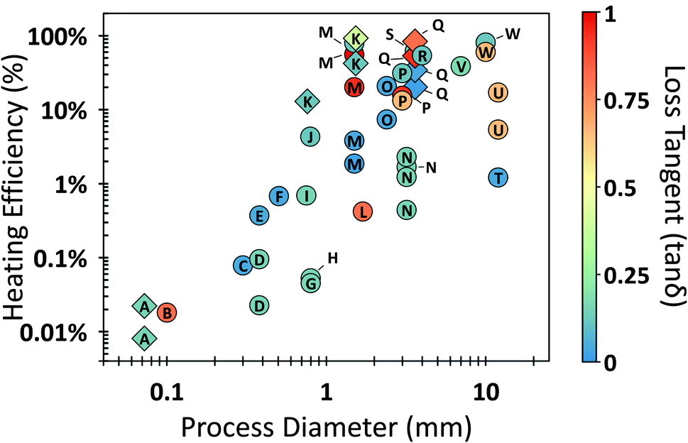 | ||
| Fig. 14 Calorimetric heating efficiency of MW-heated continuous-flow processes. Diamond-shaped data represent works that optimize heating efficiency. Referenced works correspond to overlayed enumeration as follows: A,271 B,254 C,262 D,186 E,284 F,247 G,268 H,285 I,84 J,286 K,287 L,288 M,257 N,289 O,248 P,180 Q,255 R,290 S,291 T,292 U,293 V,258 and W.294 | ||
While material properties clearly matter, process geometry affects performance even more. Amongst 23 studies depicted in Fig. 14, the reactor diameter has a clearer trend than the loss tangent. Our analysis complements that of Menéndez and coworkers who found two significant trends in their meta-analysis. First, the smaller the scale of the organic synthesis, the less likely it was to report the heating efficiency, and, secondly, the smaller the process, the less the energy efficiency.295 Clearly, geometric and material optimizations are needed in MW-heated flow reactors. Damilos et al. demonstrated that the orientation of the MW-heated microreactors has a strong effect on energy efficiency, which can lead to up to 80% difference. Recently, Chen et al. showed that geometric and process optimization can be achieved simultaneously using a machine-learning surrogate model trained on multiphysics simulations.287 It is demonstrated experimentally that microchannels of ID 1 mm could attain efficiencies ∼90% with NaCl solutions, even at temperatures approaching 200 °C, which provide an upper bound of most reactions in biomass processing. The concept is to enhance energy efficiency by simultaneous optimization of the cavity, reactor, media, catalyst, and processing conditions.
We conclude that energy efficiency is severely overlooked in MW-heated chemical manufacturing. In our analysis, more than half of MW-heated continuous flow processes were less than 10% efficient. Systems as small as 1 mm can approach >90% efficiency with geometry and material properties tuning.
The current understanding of these phenomena, while far from complete, are the product of more than 35 years of ardent research. The selective heating of non-homogeneous systems has been demonstrated conclusively and drives rate enhancements. Fundamentals of selective MW heating and temperature gradients must be further investigated to understand reaction rate enhancements. More advanced temperature measurements will likely be required to support the analysis. Significant work is still needed to fully understand the circumstances and details of the local overheating effects of macroscopically homogeneous systems. While highly efficient MW-heated systems can be achieved, researchers interested in green chemistry principles (Fig. 2) should work more assiduously to ensure MW-heated microfluidic systems are indeed operationally efficient, with special attention being paid to configurational optimization.
The knowledge generated by these pursuits will provide a foundation for understanding energy efficiency, chemical rates, and selectivity in MW-heated chemical processes. This fundamental understanding will, in turn, allow for high-quality technoeconomic analysis. MW heating could surpass CH in efficiency and chemical reaction rates and be a pillar in electrified sustainable chemical manufacturing.
4.2 Plasma microfluidic reactors
Plasma processing is attracting attention for sustainable chemical manufacturing due to its ability to perform reactions at low temperatures and far from thermodynamic equilibrium, using electrical energy. The development of non-thermal plasma (NTP) reactors operating at atmospheric pressure has enabled the activation of very stable molecules like CH4, N2, and CO2, surpassing thermodynamic conversions.296,297 Plasma allows process intensification and versatility, suitable for decentralized chemical manufacturing with potentially low reactor and carbon footprint when renewable electricity is employed.Plasma microreactors integrate microflow with discharges confined in submillimeter scales, enabling a highly reactive environment at mild operating conditions and low energy input (extremely non-equilibrium conditions).298,299 Dielectric barrier discharge (DBD) plasma microreactors are the most common: the employment of at least one dielectric layer between the electrodes provides stable operation. The enhanced interfacial area between phases and mass transfer at the micro-scale is particularly beneficial for plasma processing where the reactive species forming in the gas phase are adjacent to a liquid or solid. Whilst continuous-flow plasma reactors are common for gas-phase, liquid treatment is usually limited to batch reactors. The development of continuous gas–liquid plasma microreactors could enhance productivity. The design versatility of plasma microreactors and the reliance on just a carrier gas and electrical energy make them particularly attractive for green chemical synthesis in a catalyst-free fashion.
Several configurations have been proposed with gas bubbles and adjacent gas–liquid microchannels representing the most prominent for liquid synthesis. For gas conversion, a few reactors have also included a catalyst to enhance selectivity to the target compound. Current applications of plasma microreactors, summarized in Table 7, span between gas conversion and liquid functionalization processes.
| Applications | Plasma treatments | Results |
|---|---|---|
| Methane reforming300 | Gliding arc with and without catalyst (Ni supported on alumina–silica) | Increased methane conversion with catalyst (50% vs. 32%), comparable H2 and C2H2 selectivity (75–90%, respectively) |
| Methane partial oxidation301,302 | Coaxial DBD reactor with pulsed water injection and external cooling | Shift in product selectivity and methane conversion upon water injection. Promotoed condensation of formaldehyde and methanol. High concentration of H2O2 detected |
| Propane oxidative conversion303–305 | DBD plasma in a microchannel. Li/MgO catalyst layers on reactor wall | Significant C–C recombination with formation of C4+ species (>20% selectivity at 22% conversion). Increased conversion and propylene selectivity with catalyst |
| CO2 dissociation306 | Packed-bed coaxial DBD microreactor | 50–55% CO2 conversion at long residence time and low electrode gap. Low dielectric constant of the packing material results in higher conversion. Particle size effect is material-specific |
| Cyclohexane oxidation307 | Microfluidic chip, DBD, sine 2 kHz at 6–7 kVpp, liquid flow 6–24 μl min−1, O2 flow 0.5–2 ml min−1 | Mostly cyclohexanol and cyclohexanone, 36% conversion at high residence time 104 s, with 82% selectivity to oxygenates at lower residence times 26 s |
| Cyclohexane amination308 | Microfluidic chip, dielectric barrier discharge (DBD), liquid (pure HC) flow 8 μl min−1, NH3 flow 5 ml min−1 | 20% conversion, 50% selectivity to cyclohexylamine; higher selectivity at higher NH3 fraction |
| trans-Stilbene epoxidation309 | Microfluidic chip, dielectric barrier discharge (DBD), liquid (solution in ACN) flow 1 ml min−1, He/O2 flow 1 ml min−1 | Recirculation and short bubble-liquid contact times; 33% conversion and 94% epoxide selectivity |
| DI water oxidation310 | Helical microreactor in coaxial dielectric barrier discharge (DBD) configuration, liquid flow 0.2 ml min−1, He flow 320 ml min−1 | Highly concentrated H2O2 >25 mM at production rate ∼0.1 μmol s−1 and energy yield of ∼4 g kW−1 h−1 |
 | ||
| Fig. 15 Microfluidic chip proposed for plasma-assisted processes. (a–c) Microfluidic chip design and picture of the discharge. (d) Distribution of the reaction products of cyclohexane in an O2 plasma at different residence times of the liquid in the discharge. Reproduced from ref. 307 with permission from the Royal Society of Chemistry. | ||
The same microfluidic reactor was employed for the amination of cyclohexane using an ammonia plasma to produce cyclohexylamine.308 Other products were cyclohexene (major fraction) and various molecular weight compounds produced from the fragmentation and oligomerization of cyclohexane. A higher cyclohexylamine selectivity was observed upon decreasing the cyclohexane to ammonia ratio, with a maximum of 50% at ∼20% conversion. Recent work introduced a plasma microchip for epoxidation reactions. The effluent of a He/O2 discharge serves as the oxygen donor for the epoxidation of trans-stilbene (Fig. 16).309 The plasma generates atomic oxygen O(3P) for epoxidation, while ozone O3 (ozonolysis) leads to benzaldehyde. Optimized experiments with continuous liquid recirculation and short bubble-liquid contact time of ∼2 s achieve selectivity of ∼94% of epoxide at ∼33% conversion.
 | ||
| Fig. 16 Microfluidic chip for epoxidation of trans-stilbene in a He/O2 plasma discharge. (a and b) Design of the chip. (c) Proposed reaction scheme. Reproduced from ref. 309 with permission from Elsevier, copyright 2018. | ||
Our group proposed a helical, modular biphasic plasma microreactor using a coaxial DBD that possesses fabrication simplicity and residence time tunability for de-centralized oxidative processing (Fig. 17).310 We applied our set-up to the continuous production of highly concentrated hydrogen peroxide (H2O2) in a He plasma in contact with de-ionized water. The high gas/liquid flow ratio provided high interfacial area, combined with control of the residence time (by adjusting the gas flow rate and reactor geometry independently) and efficient heating, led to H2O2 concentrations >25 mM without compromising production rate (∼0.1 μmol s−1) and energy yield (∼4 g kW−1 h−1). This set-up could offer a more sustainable alternative to the waste and energy intensive antraquinone process currently employed for large scale production of H2O2. This process relies on catalytic cycles of hydrogenation and oxygenation of an organic substrate, whereas the plasma microreactor runs on (preferably renewable) electricity and water for the production of one of the most relevant chemicals of modern society.
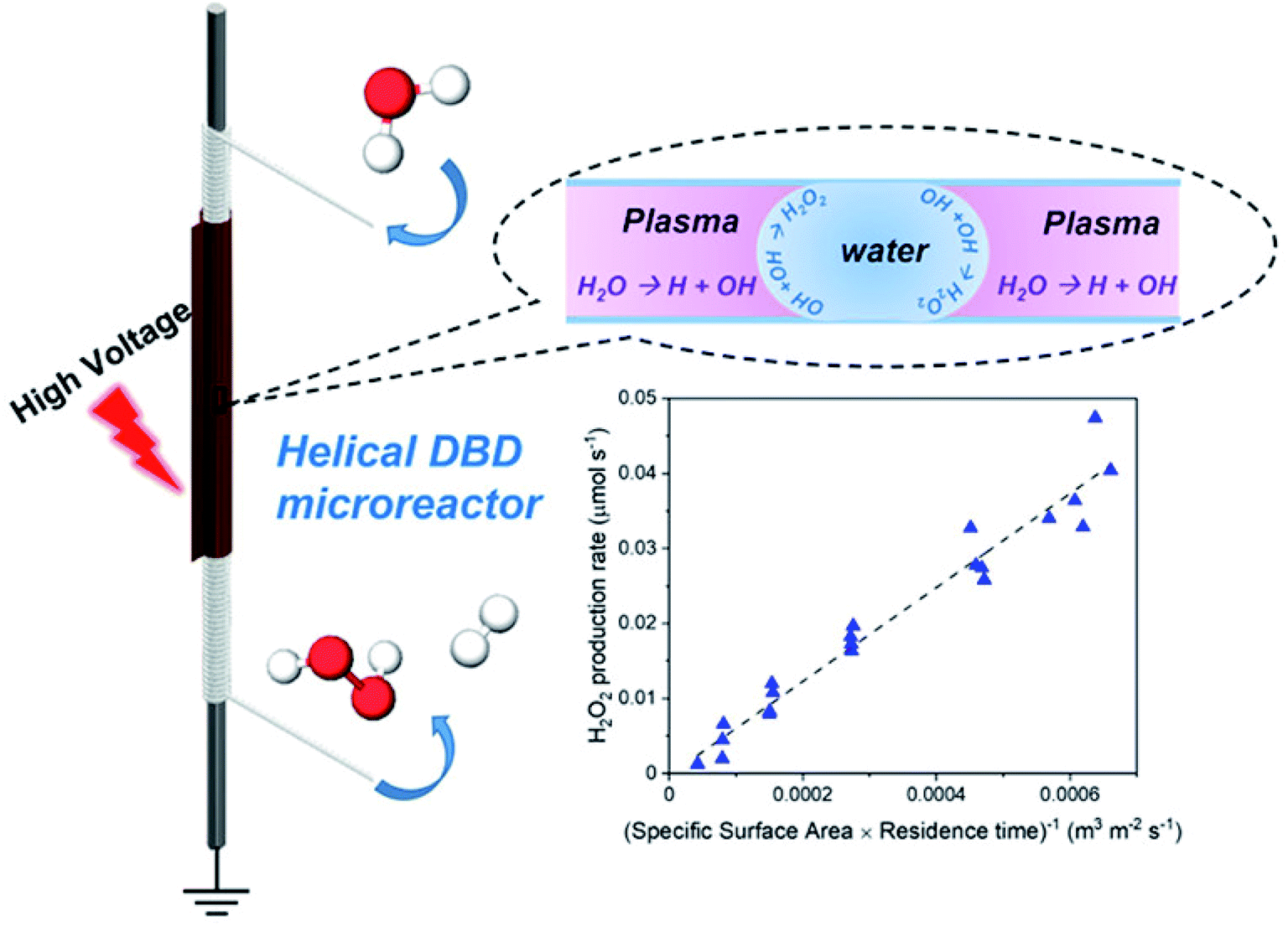 | ||
| Fig. 17 Coaxial dielectric barrier discharge (DBD) microreactor assembly for continuous production of concentrated hydrogen peroxide (H2O2). The production rate is directly correlated to the interfacial area and residence time in the plasma region. Reproduced with permission from ref. 310 with permission from the American Chemical Society, Copyright 2022. | ||
5 Beyond the lab scale
Microscale devices can handle small volumes but are typically unfit for large product volumes due to clogging, non-uniform flow distribution, catalyst regeneration issues, etc. The question raised then is whether microsystems and electrification can be practical for commercialization. There are not enough studies to answer this question. Yet, some takeaway points are clear. First, one has to consider the production scale. Distributed manufacturing will handle much smaller volumes than plants with the typical economy of scale. In this regard, microscale and electrification may be ideal and suitable for the job. Second, one has to consider the integration of microdevices with emphasis on flow distribution and heat integration. Numbering-up or scaling-out microchannels with the same flow patterns and residence time could reach sufficient scale. One of the earliest demonstrations is MIT's work315 of ten silicon micro packed-bed reactors to achieve ∼100 kg per year phosgene synthesis. The small volume and high price of pharmaceuticals make these profitable. Yet, this demonstration does not answer the commercialization potential for other application domains where scales are larger and profit is less. It is clear that designing distributors to ensure uniform flow and the same pressure drop across multichannel systems is critical. For example, Conchouso et al.316 developed a multi-layer flow distributor with 128 flow-focusing droplet generators in a parallel and circular array. Similarly, Hoang et al.317 proposed multi-junction flow distributors to ensure droplet break-up. Al-Rawashdeh et al.318 used a barrier-based microreactor to hydrogenate phenylacetylene to styrene and ethylbenzene with <10% difference in 8 reaction channels for the gas–liquid Taylor flow. A microsieve dispersion could scale up a typical T-junction micromixer.319 Wang et al.320 utilized CFD simulations to reach >100-fold productivity improvement. These examples showcase the path forward for engineering modules made of microsystems. Heat integration and temperature uniformity are also essential, as cold and hot channels can create a malfunction and device failure (flow distribution contributes to this). Stacking multiple reaction channels is a commonly used strategy. For example, Mettler et al.321 used a parallel-plate reactor with alternating combustion and steam reforming channels for syngas production. Similarly, stacked reaction plates with heating/cooling plates enhance heat transfer for rapid reactions delivering 237 g min−1 of product with similar performance to a lab-scale system.322,323Third, the dimensions of a laboratory reactor are often picked arbitrarily. One could size up a system to a larger scale with the same performance while retaining the advantages at the micro-scale, such as fast mixing and excellent heat and mass transfer. Elvira et al.324 found the hydrodynamics behavior is similar in the 0.5 mm and 1 mm microchannel, but drastically changes in the 5 mm microchannel. Similarly, Krummradt et al.325 observed similar reaction yields using less than 1 mm microreactor. Recently, Desir et al.28 discussed the scale-up for fructose dehydration from 500 μm to 8 mm using the Dean number (De) and the Peclet number as descriptors. Guo et al. reported minor mass transfer limitations for the tandem reaction upon scaling the reactor length and flowrates 14× while maintaining the same residence time in biphasic systems.25 In addition to simply increase the reactor dimensions, altering reactor shape can improve the productivity as well. For example, deep microchannels provide enhanced throughput while maintaining a uniform flow distribution.326 Slit-like microchannels yield great extraction efficiency and comparable throughput as 300 single microchannels.327 The heart-shaped Corning Advanced-Flow reactor retain similar interfacial surface area and mass transfer rate as the typical microreactor while improving the operating flow rate by 8-fold.328
We propose combining size up and numbering up as a strategy to minimize material of construction and the number of units. Ensuring transport characteristics is the key point when enlarging the reactor dimensions. On the other hand, uniform flow and residence time distribution and similar pressure drop are considered for increasing the reactor numbers. While utilizing both strategies to scale-up the system, all of these concerns should be considered. Indeed, Zhang et al.329 studied the flow distribution and mixing characteristics for different combinations of reactor numbers and dimensions and observed different velocity profiles. Bhosekar et al.330 optimized a biomass refinery balancing the increase of the microchannel size and their number. Wang et al.331 combined sizing-up and numbering-up strategy to achieve 160-fold improvement in processing capacity by increasing the reactor dimension by 16-fold and the number of channels by 10-fold. More investigations are needed to develop further understandings on effectively combining the numbering-up and size-up approach.
Fourth, TEA and LCA are vital metrics for sustainable manufacturing. The Novartis and MIT collaborative work demonstrated an integrated continuous manufacturing plant for active pharmaceutical ingredients332 for the synthesis, separation, crystallization, and formulation of 2.7 × 10⁶ aliskiren hemifumarate tablets per year. Zhang et al.333 developed another platform for nicardipine hydrochloride, ciprofloxacin hydrochloride, neostigmine methylsulfate, and rufinamide.333 Jolliffe and Gerogiorgis334 evaluated the economic viability of ibuprofen and artemisinin. The capital expenditure (CapEx) and operating expenditure (OpEx) were lower by 57% and 52%, respectively, and the material efficiency was also better using the Environmental (E)-factors than typical batch processes.334 The high value of pharmaceutical ingredients makes the TEA favorable and the answer to the commercialization prospect hazy. Beyond pharmaceuticals, Corning achieved 10000 metric tons annual throughput of agrochemicals using their Advanced-Flow™ Reactor Technology.335 Desir et al.28 evaluated the scale and economic viability of the HMF production from fructose for the medium-scale farms. A few hundred reactors can meet demand, demonstrating the potential of microtechnology for distributed manufacturing with a target of 2.5 tons per day production rate. With the growing environmental concerns, Bhosekar et al.330 employed a multi-objective optimization approach to obtain Pareto optimal solutions for the tradeoff between profit and environmental impact of a biomass refinery. These limited number of examples are encouraging. However, TEA and LCA are crucial vectors for guiding decisions. It is also interesting to contrast the above production scales of 2.5 tons per day for biomass of a midsize farm to 100 kg per year of phosgene synthesis to realize the scale of challenges for chemical manufacturing.
6 Concluding remarks
This review advocated that sustainability demands a holistic approach. It requires applying green principles from wells-to-wheels, including feedstock extraction and handling, manufacturing of products, recycling end-of-pipe products, and using renewable carbon and energy sources. We reviewed the fundamental characteristics of flow chemistry, its applications to renewable resources, and its integration with electrification, such as microwaves and plasmas. Flow microtechnology is excellent for sustainable manufacturing due to meeting multiple green principles, including minimizing waste of solvents and materials, reducing the cost of construction, increasing energy and atom efficiency, and providing safer processes. Combining microreactors with plasma and microwaves holds tremendous promise toward sustainable manufacturing. This integration can improve energy efficiency and safety while offering unique advantages from electrification. Examples of plasma processing include overcoming thermodynamic limitations and activating very stable molecules. Examples of microwaves include rapid and volumetric heating and temperature gradients that can be harnessed to provide superior performance. More research on the design principles and scalabilities, including TEA and LCA of entire processes, is needed to advance such integrated technologies further. In this regard, one has to go beyond the flow chemistry and also consider heating, quenching, separation, and purification. Process integration with attention to micro-scale separation and purification is needed. For example, traditional distillation may not be suitable at the micro-scale, and handling solids and clogging associated with many unconventional feedstocks remains challenging. Further advancements in the fabrication, integration, and materials of electrified microflow chemistry are required.Data availability
As this is a review and all data discussed are cited, provided in tables, and available in literature, we will refrain from providing this in yet another form.Author contributions
Tai-Ying Chen: conceptualization, visualization, writing – original draft preparation, writing – reviewing and editing, supervision. Yung Wei Hsiao: conceptualization, visualization, formal analysis, writing – original draft preparation, writing – reviewing and editing. Montgomery Baker-Fales: conceptualization, visualization, formal analysis, writing – original draft preparation, writing – reviewing and editing. Fabio Cameli: visualization, writing – original draft preparation, writing - reviewing and editing. Panagiotis Dimitrakellis: writing – original draft preparation. Dionisios G. Vlachos: conceptualization, supervision, writing – reviewing and editing, project administration, funding acquisition.Conflicts of interest
There are no conflicts of interest to declare.Acknowledgements
Funding from the RAPID manufacturing institute, supported by the Department of Energy (DOE) Advanced Manufacturing Office (AMO), award numbers DE-EE0007888-7.6 and DE-EE0007888-8.3 are gratefully acknowledged. RAPID projects at the University of Delaware are also made possible in part by funding provided by the State of Delaware. The Delaware Energy Institute gratefully acknowledges the support and partnership of the State of Delaware in furthering the essential scientific research being conducted through the RAPID projects. The authors acknowledge fruitful discussions with Dr Abhinav Malhotra and Dr Natalia Rodriguez Quiroz.References
- K. Kümmerer, J. H. Clark and V. G. Zuin, Rethinking Chemistry for a Circular Economy, Science, 2020, 367(6476), 369–370, DOI:10.1126/SCIENCE.ABA4979.
- L. S. T. J. Korley, T. H. Epps, B. A. Helms and A. J. Ryan, Toward Polymer Upcycling-Adding Value and Tackling Circularity, Science, 2021, 373(6550), 66–69, DOI:10.1126/SCIENCE.ABG4503/ASSET/25C8B34D-D1F7-4E8E-863D-BDBE3D80CEA2/ASSETS/GRAPHIC/373_66_F1.JPEG.
- E. O. Ebikade, S. Sadula, Y. Gupta and D. G. Vlachos, A Review of Thermal and Thermocatalytic Valorization of Food Waste, Green Chem., 2021, 23(8), 2806–2833, 10.1039/D1GC00536G.
- C. O. Tuck, E. Pérez, I. T. Horváth, R. A. Sheldon and M. Poliakoff, Valorization of Biomass: Deriving More Value from Waste, Science, 2012, 337(6095), 695–699, DOI:10.1126/SCIENCE.1218930/ASSET/7DAF6949-E080-42B9-BC8E-C98CCAE997F5/ASSETS/GRAPHIC/337_695_F5.JPEG.
- M. Jouny, W. Luc and F. Jiao, High-Rate Electroreduction of Carbon Monoxide to Multi-Carbon Products, Nat. Catal., 2018, 1(10), 748–755, DOI:10.1038/s41929-018-0133-2.
- S. Gu, B. Xu and Y. Yan, Electrochemical Energy Engineering: A New Frontier of Chemical Engineering Innovation, Annu. Rev. Chem. Biomol. Eng., 2014, 5, 429–454, DOI:10.1146/annurev-chembioeng-060713-040114.
- T. Hisatomi and K. Domen, Reaction Systems for Solar Hydrogen Production via Water Splitting with Particulate Semiconductor Photocatalysts, Nat. Catal., 2019, 2(5), 387–399, DOI:10.1038/s41929-019-0242-6.
- S. Berardi, S. Drouet, L. Francàs, C. Gimbert-Suriñach, M. Guttentag, C. Richmond, T. Stoll and A. Llobet, Molecular Artificial Photosynthesis, Chem. Soc. Rev., 2014, 43(22), 7501–7519, 10.1039/C3CS60405E.
- R. A. Sheldon, Fundamentals of Green Chemistry: Efficiency in Reaction Design, Chem. Soc. Rev., 2012, 41(4), 1437–1451, 10.1039/c1cs15219j.
- P. T. Anastas and J. B. Zimmerman, The Twelve Principles of Green Engineering as a Foundation for Sustainability, Sustainability Sci. Eng., 2006, 1(C), 11–32, DOI:10.1016/S1871-2711(06)80009-7.
- N. Winterton, News and Views, Green Chem., 2001, 3(6), G73–G81, 10.1039/B110187K.
- S. L. Y. Tang, R. L. Smith and M. Poliakoff, Principles of Green Chemistry: PRODUCTIVELY, Green Chem., 2005, 7(11), 761–762, 10.1039/B513020B.
- K. S. Elvira, X. C. I Solvas, R. C. R. Wootton and A. J. Demello, The Past, Present and Potential for Microfluidic Reactor Technology in Chemical Synthesis, Nat. Chem., 2013, 5(11), 905–915, DOI:10.1038/nchem.1753.
- S. G. Newman and K. F. Jensen, The Role of Flow in Green Chemistry and Engineering, Green Chem., 2013, 15(6), 1456–1472, 10.1039/c3gc40374b.
- K. F. Jensen, Flow Chemistry—Microreaction Technology Comes of Age, AIChE J., 2017, 63(3), 858–869 CrossRef CAS.
- S. Caratzoulas, M. E. Davis, R. J. Gorte, R. Gounder, R. F. Lobo, V. Nikolakis, S. I. Sandler, M. A. Snyder, M. Tsapatsis and D. G. Vlachos, Challenges of and Insights into Acid-Catalyzed Transformations of Sugars, J. Phys. Chem. C, 2014, 118(40), 22815–22833, DOI:10.1021/jp504358d.
- D. M. Alonso, J. Q. Bond and J. A. Dumesic, Catalytic Conversion of Biomass to Biofuels, Green Chem., 2010, 12(9), 1493–1513, 10.1039/c004654j.
- A. Demirbaş, Biomass Resource Facilities and Biomass Conversion Processing for Fuels and Chemicals, Energy Convers. Manage., 2001, 42(11), 1357–1378, DOI:10.1016/S0196-8904(00)00137-0.
- D. A. Bulushev and J. R. H. Ross, Catalysis for Conversion of Biomass to Fuels via Pyrolysis and Gasification: A Review, Catal. Today, 2011, 171(1), 1–13, DOI:10.1016/j.cattod.2011.02.005.
- R. A. Sheldon, M. Poliakoff, E. Perez, C. O. Tuck and I. T. Horvath, Valorization of Biomass: Deriving More Value from Waste, Science, 2012, 337(6095), 695–699, DOI:10.1126/science.1218930.
- G. W. Huber, S. Iborra and A. Corma, Synthesis of Transportation Fuels from Biomass: Chemistry, Catalysts, and Engineering, Chem. Rev., 2006, 106(9), 4044–4098, DOI:10.1021/CR068360D.
- A. Hommes, H. J. Heeres and J. Yue, Catalytic Transformation of Biomass Derivatives to Value-Added Chemicals and Fuels in Continuous Flow Microreactors, ChemCatChem, 2019, 11(19), 4671–4708, DOI:10.1002/cctc.201900807.
- Y. Muranaka, H. Nakagawa, R. Masaki, T. Maki and K. Mae, Continuous 5-Hydroxymethylfurfural Production from Monosaccharides in a Microreactor, Ind. Eng. Chem. Res., 2017, 56(39), 10998–11005, DOI:10.1021/acs.iecr.7b02017.
- T. Shimanouchi, Y. Kataoka, T. Tanifuji, Y. Kimura, S. Fujioka and K. Terasaka, Chemical Conversion and Liquid-Liquid Extraction of 5-Hydroxymethylfurfural from Fructose by Slug Flow Microreactor, AIChE J., 2016, 62(6), 2135–2143, DOI:10.1002/aic.15201.
- W. Guo, H. J. Heeres and J. Yue, Continuous Synthesis of 5-Hydroxymethylfurfural from Glucose Using a Combination of AlCl3 and HCl as Catalyst in a Biphasic Slug Flow Capillary Microreactor, Chem. Eng. J., 2020, 381(2), 122754, DOI:10.1016/j.cej.2019.122754.
- M. S. Mettler, D. G. Vlachos and P. J. Dauenhauer, Top Ten Fundamental Challenges of Biomass Pyrolysis for Biofuels, Energy Environ. Sci., 2012, 5(7), 7797–7809, 10.1039/C2EE21679E.
- A. Oasmaa and D. Meier, Norms and Standards for Fast Pyrolysis Liquids: 1. Round Robin Test, J. Anal. Appl. Pyrolysis, 2005, 73(2), 323–334, DOI:10.1016/J.JAAP.2005.03.003.
- P. Desir, B. Saha and D. G. Vlachos, Ultrafast Flow Chemistry for the Acid-Catalyzed Conversion of Fructose, Energy Environ. Sci., 2019, 12(8), 2463–2475, 10.1039/c9ee01189g.
- Y. He, S. Guo, K. Chen, S. Li, L. Zhang and S. Yin, Sustainable Green Production: A Review of Recent Development on Rare Earths Extraction and Separation Using Microreactors, ACS Sustainable Chem. Eng., 2019, 7(21), 17616–17626, DOI:10.1021/acssuschemeng.9b03384.
- J. Zhang, K. Wang, A. R. Teixeira, K. F. Jensen and G. Luo, Design and Scaling Up of Microchemical Systems: A Review, Annu. Rev. Chem. Biomol. Eng., 2017, 8(1), 285–305, DOI:10.1146/annurev-chembioeng-060816-101443.
- A. Tanimu, S. Jaenicke and K. Alhooshani, Heterogeneous Catalysis in Continuous Flow Microreactors: A Review of Methods and Applications, Chem. Eng. J., 2017, 327, 792–821, DOI:10.1016/j.cej.2017.06.161.
- H. P. L. Gemoets, Y. Su, M. Shang, V. Hessel, R. Luque and T. Noël, Liquid Phase Oxidation Chemistry in Continuous-Flow Microreactors, Chem. Soc. Rev., 2016, 45(1), 83–117, 10.1039/c5cs00447k.
- I. Rossetti and M. Compagnoni, Chemical Reaction Engineering, Process Design and Scale-up Issues at the Frontier of Synthesis: Flow Chemistry, Chem. Eng. J., 2016, 296, 56–70, DOI:10.1016/j.cej.2016.02.119.
- V. Hessel, D. Kralisch, N. Kockmann, T. Noël and Q. Wang, Novel Process Windows for Enabling, Accelerating, and Uplifting Flow Chemistry, ChemSusChem, 2013, 6(5), 746–789, DOI:10.1002/cssc.201200766.
- J. I. Yoshida, H. Kim and A. Nagaki, Green and Sustainable Chemical Synthesis Using Flow Microreactors, ChemSusChem, 2011, 4(3), 331–340, DOI:10.1002/cssc.201000271.
- K. Wang, L. Li, P. Xie and G. Luo, Liquid–Liquid Microflow Reaction Engineering, React. Chem. Eng., 2017, 2(5), 611–627, 10.1039/C7RE00082K.
- B. Gutmann, D. Cantillo and C. O. Kappe, Continuous-Flow Technology—A Tool for the Safe Manufacturing of Active Pharmaceutical Ingredients, Angew. Chem., Int. Ed., 2015, 54(23), 6688–6728, DOI:10.1002/ANIE.201409318.
- S. V. Ley, D. E. Fitzpatrick, R. M. Myers, C. Battilocchio and R. J. Ingham, Machine-Assisted Organic Synthesis, Angew. Chem., Int. Ed., 2015, 54(35), 10122–10136, DOI:10.1002/ANIE.201501618.
- A. Günther and K. F. Jensen, Multiphase Microfluidics: From Flow Characteristics to Chemical and Materials Synthesis, Lab Chip, 2006, 6(12), 1487–1503, 10.1039/B609851G.
- T. Y. Chen, Z. Cheng, P. Desir, B. Saha and D. G. Vlachos, Fast Microflow Kinetics and Acid Catalyst Deactivation in Glucose Conversion to 5-Hydroxymethylfurfural, React. Chem. Eng., 2021, 6(1), 152–164, 10.1039/d0re00391c.
- T. D. Swift, H. Nguyen, A. Anderko, V. Nikolakis and D. G. Vlachos, Tandem Lewis/Brønsted Homogeneous Acid Catalysis: Conversion of Glucose to 5-Hydoxymethylfurfural in an Aqueous Chromium(III) Chloride and Hydrochloric Acid Solution, Green Chem., 2015, 17(10), 4725–4735, 10.1039/c5gc01257k.
- T. D. Swift, C. Bagia, V. Choudhary, G. Peklaris, V. Nikolakis and D. G. Vlachos, Kinetics of Homogeneous Brønsted Acid Catalyzed Fructose Dehydration and 5-Hydroxymethyl Furfural Rehydration: A Combined Experimental and Computational Study, ACS Catal., 2014, 4(1), 259–267, DOI:10.1021/cs4009495.
- K. Wang, L. Xie, Y. Lu and G. Luo, Generating Microbubbles in a Co-Flowing Microfluidic Device, Chem. Eng. Sci., 2013, 100, 486–495, DOI:10.1016/J.CES.2013.02.021.
- V. Hessel, H. Löwe and F. Schönfeld, Micromixers—a Review on Passive and Active Mixing Principles, Chem. Eng. Sci., 2005, 60(8–9), 2479–2501, DOI:10.1016/J.CES.2004.11.033.
- S. Panić, S. Loebbecke, T. Tuercke, J. Antes and D. Bošković, Experimental Approaches to a Better Understanding of Mixing Performance of Microfluidic Devices, Chem. Eng. J., 2004, 101(1–3), 409–419, DOI:10.1016/J.CEJ.2003.10.026.
- A. A. Yagodnitsyna, A. V. Kovalev and A. V. Bilsky, Flow Patterns of Immiscible Liquid-Liquid Flow in a Rectangular Microchannel with T-Junction, Chem. Eng. J., 2016, 303, 547–554, DOI:10.1016/j.cej.2016.06.023.
- P. Desir, T. Y. Chen, M. Bracconi, B. Saha, M. Maestri and D. G. Vlachos, Experiments and Computations of Microfluidic Liquid-Liquid Flow Patterns, React. Chem. Eng., 2020, 5(1), 39–50, 10.1039/c9re00332k.
- T. Y. Chen, P. Desir, M. Bracconi, B. Saha, M. Maestri and D. G. Vlachos, Liquid-Liquid Microfluidic Flows for Ultrafast 5-Hydroxymethyl Furfural Extraction, Ind. Eng. Chem. Res., 2021, 60(9), 3723–3735, DOI:10.1021/acs.iecr.0c05759.
- J. D. Tice, A. D. Lyon and R. F. Ismagilov, Effects of Viscosity on Droplet Formation and Mixing in Microfluidic Channels, Anal. Chim. Acta, 2004, 507(1), 73–77, DOI:10.1016/J.ACA.2003.11.024.
- Y. Roman-Leshkov and J. A. Dumesic, Solvent Effects on Fructose Dehydration to 5-Hydroxymethylfurfural in Biphasic Systems Saturated with Inorganic Salts, Top. Catal., 2009, 52(3), 297–303, DOI:10.1007/s11244-008-9166-0.
- V. Choudhary, S. H. Mushrif, C. Ho, A. Anderko, V. Nikolakis, N. S. Marinkovic, A. I. Frenkel, S. I. Sandler and D. G. Vlachos, Insights into the Interplay of Lewis and Brønsted Acid Catalysts in Glucose and Fructose Conversion to 5-(Hydroxymethyl)Furfural and Levulinic Acid in Aqueous Media, J. Am. Chem. Soc., 2013, 135(10), 3997–4006, DOI:10.1021/ja3122763.
- Y. Roman-Leshkov, J. N. Chheda and J. A. Dumesic, Phase Modifiers Promote Efficient Production of Hydroxymethylfurfural from Fructose, Science, 2006, 312(5782), 1933–1937, DOI:10.1126/science.1126337.
- W. Guo, Z. Zhang, J. Hacking, H. J. Heeres and J. Yue, Selective Fructose Dehydration to 5-Hydroxymethylfurfural from a Fructose-Glucose Mixture over a Sulfuric Acid Catalyst in a Biphasic System: Experimental Study and Kinetic Modelling, Chem. Eng. J., 2021, 409, 128182, DOI:10.1016/j.cej.2020.128182.
- M. N. Kashid, A. Renken and L. Kiwi-Minsker, Gas-Liquid and Liquid-Liquid Mass Transfer in Microstructured Reactors, Chem. Eng. Sci., 2011, 3876–3897, DOI:10.1016/j.ces.2011.05.015.
- M. Madadelahi and A. Shamloo, Droplet-Based Flows in Serpentine Microchannels: Chemical Reactions and Secondary Flows, Int. J. Multiphase Flow, 2017, 97, 186–196, DOI:10.1016/j.ijmultiphaseflow.2017.08.010.
- M. N. Kashid, A. Renken and L. Kiwi-Minsker, Influence of Flow Regime on Mass Transfer in Different Types of Microchannels, Ind. Eng. Chem. Res., 2011, 50(11), 6906–6914, DOI:10.1021/ie102200j.
- G. Li, X. Pu, M. Shang, L. Zha and Y. Su, Intensification of Liquid–Liquid Two-Phase Mass Transfer in a Capillary Microreactor System, AIChE J., 2019, 65(1), 334–346, DOI:10.1002/aic.16211.
- C. X. Zhao and A. P. J. Middelberg, Two-Phase Microfluidic Flows, Chem. Eng. Sci., 2011, 66(7), 1394–1411, DOI:10.1016/J.CES.2010.08.038.
- P. Desir, T. Y. Chen, M. Bracconi, B. Saha, M. Maestri and D. G. Vlachos, Experiments and Computations of Microfluidic Liquid–Liquid Flow Patterns, React. Chem. Eng., 2019, 5(1), 39–50, 10.1039/C9RE00332K.
- Y. Haroun, L. Raynal and D. Legendre, Mass Transfer and Liquid Hold-up Determination in Structured Packing by CFD, Chem. Eng. Sci., 2012, 75, 342–348, DOI:10.1016/j.ces.2012.03.011.
- Y. Haroun, D. Legendre and L. Raynal, Volume of Fluid Method for Interfacial Reactive Mass Transfer: Application to Stable Liquid Film, Chem. Eng. Sci., 2010, 65(10), 2896–2909, DOI:10.1016/j.ces.2010.01.012.
- Y. Li, R. K. Reddy, C. S. S. R. Kumar and K. Nandakumar, Computational Investigations of the Mixing Performance inside Liquid Slugs Generated by a Microfluidic T-Junction, Biomicrofluidics, 2014, 8(5), 1–18, DOI:10.1063/1.4900939.
- M. N. Kashid, D. W. Agar and S. Turek, CFD Modelling of Mass Transfer with and without Chemical Reaction in the Liquid-Liquid Slug Flow Microreactor, Chem. Eng. Sci., 2007, 62(18–20), 5102–5109, DOI:10.1016/j.ces.2007.01.068.
- J. H. Xu, S. W. Li, J. Tan and G. S. Luo, Correlations of Droplet Formation in T-Junction Microfluidic Devices: From Squeezing to Dripping, Microfluid. Nanofluid., 2008, 5(6), 711–717, DOI:10.1007/s10404-008-0306-4.
- T. Thorsen, R. W. Roberts, F. H. Arnold and S. R. Quake, Dynamic Pattern Formation in a Vesicle-Generating Microfluidic Device, Phys. Rev. Lett., 2001, 86(18), 4163–4166, DOI:10.1103/PhysRevLett.86.4163.
- E. Castro-Hernández, V. Gundabala, A. Fernández-Nieves and J. M. Gordillo, Scaling the Drop Size in Coflow Experiments, New J. Phys., 2009, 11(7), 075021, DOI:10.1088/1367-2630/11/7/075021.
- C. C. Roberts, R. R. Rao, M. Loewenberg, C. F. Brooks, P. Galambos, A. M. Grillet and M. B. Nemer, Comparison of Monodisperse Droplet Generation in Flow-Focusing Devices with Hydrophilic and Hydrophobic Surfaces, Lab Chip, 2012, 12(8), 1540–1547, 10.1039/C2LC21197A.
- J. Tan, S. W. Li, K. Wang and G. S. Luo, Gas–Liquid Flow in T-Junction Microfluidic Devices with a New Perpendicular Rupturing Flow Route, Chem. Eng. J., 2009, 146(3), 428–433, DOI:10.1016/J.CEJ.2008.10.024.
- Y. W. Hsiao, A. Anastasopoulou, M. Ierapetritou and D. G. Vlachos, Cost and Energy Efficient Cyclic Separation of 5-Hydroxymethyl Furfural from an Aqueous Solution, Green Chem., 2021, 23(11), 4008–4023, 10.1039/d1gc00841b.
- H. Goyal, S. Sadula and D. G. Vlachos, Microwave Heating of Slurries, Chem. Eng. J., 2021, 417, 127892, DOI:10.1016/j.cej.2020.127892.
- J. Yue, Multiphase Flow Processing in Microreactors Combined with Heterogeneous Catalysis for Efficient and Sustainable Chemical Synthesis, Catal. Today, 2018, 308, 3–19, DOI:10.1016/J.CATTOD.2017.09.041.
- X. Liu, B. Ünal and K. F. Jensen, Heterogeneous Catalysis with Continuous Flow Microreactors, Catal. Sci. Technol., 2012, 2(10), 2134–2138, 10.1039/C2CY20260C.
- C. Aellig, D. Scholz, S. Conrad and I. Hermans, Intensification of TEMPO-Mediated Aerobic Alcohol Oxidations under Three-Phase Flow Conditions, Green Chem., 2013, 15(7), 1975–1980, 10.1039/C3GC40159F.
- A. Faridkhou, J. N. Tourvieille and F. Larachi, Reactions, Hydrodynamics and Mass Transfer in Micro-Packed Beds—Overview and New Mass Transfer Data, Chem. Eng. Process., 2016, 110, 80–96, DOI:10.1016/J.CEP.2016.09.016.
- A. Faridkhou and F. Larachi, Two-Phase Flow Hydrodynamic Study in Micro-Packed Beds – Effect of Bed Geometry and Particle Size, Chem. Eng. Process., 2014, 78, 27–36, DOI:10.1016/J.CEP.2014.02.005.
- L. Sang, Q. Cao, B. Xie, C. Ma and J. Zhang, Investigation of Effective Interfacial Area in Micropacked Bed Reactors, Ind. Eng. Chem. Res., 2021, 60(25), 9206–9215, DOI:10.1021/ACS.IECR.1C00416/ASSET/IMAGES/MEDIUM/IE1C00416_M020.GIF.
- L. Sang, X. Feng, J. Tu, B. Xie, G. Luo and J. Zhang, Investigation of External Mass Transfer in Micropacked Bed Reactors, Chem. Eng. J., 2020, 393, 124793, DOI:10.1016/J.CEJ.2020.124793.
- J. R. Bourne, Mixing and the Selectivity of Chemical Reactions, Org. Process Res. Dev., 2003, 471–508, DOI:10.1021/op020074q.
- H. Ganapathy, A. Shooshtari, S. Dessiatoun, M. M. Ohadi and M. Alshehhi, Hydrodynamics and Mass Transfer Performance of a Microreactor for Enhanced Gas Separation Processes, Chem. Eng. J., 2015, 266, 258–270, DOI:10.1016/J.CEJ.2014.12.028.
- Q. Li and P. Angeli, Intensified Eu(III) Extraction Using Ionic Liquids in Small Channels, Chem. Eng. Sci., 2016, 143, 276–286, DOI:10.1016/J.CES.2016.01.004.
- K. K. Singh, A. U. Renjith and K. T. Shenoy, Liquid–Liquid Extraction in Microchannels and Conventional Stage-Wise Extractors: A Comparative Study, Chem. Eng. Process., 2015, 98, 95–105, DOI:10.1016/J.CEP.2015.10.013.
- P. Plouffe, D. M. Roberge, J. Sieber, M. Bittel and A. Macchi, Liquid–Liquid Mass Transfer in a Serpentine Micro-Reactor Using Various Solvents, Chem. Eng. J., 2016, 285, 605–615, DOI:10.1016/J.CEJ.2015.09.115.
- M. Sattari-Najafabadi, M. Nasr Esfahany, Z. Wu and B. Sundén, Hydrodynamics and Mass Transfer in Liquid-Liquid Non-Circular Microchannels: Comparison of Two Aspect Ratios and Three Junction Structures, Chem. Eng. J., 2017, 322, 328–338, DOI:10.1016/J.CEJ.2017.04.028.
- M. N. Kashid, Y. M. Harshe and D. W. Agar, Liquid-Liquid Slug Flow in a Capillary: An Alternative to Suspended Drop or Film Contactors, Ind. Eng. Chem. Res., 2007, 46(25), 8420–8430, DOI:10.1021/IE070077X/ASSET/IMAGES/LARGE/IE070077XF00023.JPEG.
- J. Xu, J. Wang, F. Deng, Z. Hu and H. Wang, Green Tea Extract and Its Major Component Epigallocatechin Gallate Inhibits Hepatitis B Virus in Vitro, Antiviral Res., 2008, 78(3), 242–249, DOI:10.1016/J.ANTIVIRAL.2007.11.011.
- M. Sattari-Najafabadi, M. Nasr Esfahany, Z. Wu and B. Sunden, Mass Transfer between Phases in Microchannels: A Review, Chem. Eng. Process., 2018, 127, 213–237, DOI:10.1016/J.CEP.2018.03.012.
- Y. Zhao, Y. Su, G. Chen and Q. Yuan, Effect of Surface Properties on the Flow Characteristics and Mass Transfer Performance in Microchannels, Chem. Eng. Sci., 2010, 65(5), 1563–1570, DOI:10.1016/J.CES.2009.10.027.
- A. Woitalka, S. Kuhn and K. F. Jensen, Scalability of Mass Transfer in Liquid–Liquid Flow, Chem. Eng. Sci., 2014, 116, 1–8, DOI:10.1016/J.CES.2014.04.036.
- Y. Su, Y. Zhao, G. Chen and Q. Yuan, Liquid-Liquid Two-Phase Flow and Mass Transfer Characteristics in Packed Microchannels, Chem. Eng. Sci., 2010, 65(13), 3947–3956, DOI:10.1016/j.ces.2010.03.034.
- C. Simonnet and A. Groisman, Chaotic Mixing in a Steady Flow in a Microchannel, Phys. Rev. Lett., 2005, 94(13), 134501, DOI:10.1103/PHYSREVLETT.94.134501/FIGURES/5/MEDIUM.
- Susanti, J. G. M. Winkelman, B. Schuur, H. J. Heeres and J. Yue, Lactic Acid Extraction and Mass Transfer Characteristics in Slug Flow Capillary Microreactors, Ind. Eng. Chem. Res., 2016, 55(16), 4691–4702, DOI:10.1021/acs.iecr.5b04917.
- C. Yao, Y. Liu, C. Xu, S. Zhao and G. Chen, Formation of Liquid–Liquid Slug Flow in a Microfluidic T-Junction: Effects of Fluid Properties and Leakage Flow, AIChE J., 2018, 64(1), 346–357, DOI:10.1002/aic.15889.
- P. Garstecki, M. J. Fuerstman, H. A. Stone and G. M. Whitesides, Formation of Droplets and Bubbles in a Microfluidic T-Junction—Scaling and Mechanism of Break-Up, Lab Chip, 2006, 6(3), 437–446, 10.1039/b510841a.
- J. Tan, Y. C. Lu, J. H. Xu and G. S. Luo, Mass Transfer Characteristic in the Formation Stage of Gas–Liquid Segmented Flow in Microchannel, Chem. Eng. J., 2012, 185–186, 314–320, DOI:10.1016/J.CEJ.2012.01.054.
- J. Ren, S. He, C. Ye, G. Chen and C. Sun, The Ozone Mass Transfer Characteristics and Ozonation of Pentachlorophenol in a Novel Microchannel Reactor, Chem. Eng. J., 2012, 210, 374–384, DOI:10.1016/j.cej.2012.09.011.
- C. Yao, Z. Dong, Y. Zhao and G. Chen, Gas-Liquid Flow and Mass Transfer in a Microchannel under Elevated Pressures, Chem. Eng. Sci., 2015, 123, 137–145, DOI:10.1016/J.CES.2014.11.005.
- M. N. Kashid, A. Gupta, A. Renken and L. Kiwi-Minsker, Numbering-up and Mass Transfer Studies of Liquid–Liquid Two-Phase Microstructured Reactors, Chem. Eng. J., 2010, 158(2), 233–240, DOI:10.1016/J.CEJ.2010.01.020.
- J. Tang, X. Zhang, W. Cai and F. Wang, Liquid–Liquid Extraction Based on Droplet Flow in a Vertical Microchannel, Exp. Therm. Fluid Sci., 2013, 49, 185–192, DOI:10.1016/J.EXPTHERMFLUSCI.2013.04.017.
- L. Bai, S. Zhao, Y. Fu and Y. Cheng, Experimental Study of Mass Transfer in Water/Ionic Liquid Microdroplet Systems Using Micro-LIF Technique, Chem. Eng. J., 2016, 298, 281–290, DOI:10.1016/j.cej.2016.04.034.
- A. Abdollahi, R. N. Sharma and A. Vatani, Fluid Flow and Heat Transfer of Liquid-Liquid Two Phase Flow in Microchannels: A Review, Int. Commun. Heat Mass Transfer, 2017, 84, 66–74, DOI:10.1016/J.ICHEATMASSTRANSFER.2017.03.010.
- A. Asthana, I. Zinovik, C. Weinmueller and D. Poulikakos, Significant Nusselt Number Increase in Microchannels with a Segmented Flow of Two Immiscible Liquids: An Experimental Study, Int. J. Heat Mass Transfer, 2011, 54(7–8), 1456–1464, DOI:10.1016/J.IJHEATMASSTRANSFER.2010.11.048.
- Z. Che, T. N. Wong and N. T. Nguyen, Heat Transfer in Plug Flow in Cylindrical Microcapillaries with Constant Surface Heat Flux, Int. J. Therm. Sci., 2013, 64, 204–212, DOI:10.1016/J.IJTHERMALSCI.2012.09.006.
- S. Kuhn, R. L. Hartman, M. Sultana, K. D. Nagy, S. Marre and K. F. Jensen, Teflon-Coated Silicon Microreactors: Impact on Segmented Liquid-Liquid Multiphase Flows, Langmuir, 2011, 27(10), 6519–6527, DOI:10.1021/la2004744.
- D. Bošković, S. Loebbecke, G. A. Gross and J. M. Koehler, Residence Time Distribution Studies in Microfluidic Mixing Structures, Chem. Eng. Technol., 2011, 34(3), 361–370, DOI:10.1002/CEAT.201000352.
- M. R. Gaddem, S. Ookawara, K. D. P. Nigam, S. Yoshikawa and H. Matsumoto, Hydrodynamics and Mixing in a Novel Design of Compact Microreactors: Arc Flow Inverters, Chem. Eng. Process., 2021, 108770, DOI:10.1016/J.CEP.2021.108770.
- É. S. Siguemoto, L. Leite Reche, J. A. W. Gut and M. S. A. Palma, Residence Time Distribution of a Capillary Microreactor Used for Pharmaceutical Synthesis, Chem. Eng. Technol., 2020, 43(3), 429–435, DOI:10.1002/CEAT.201900478.
- S. A. Kazemi Oskooei and D. Sinton, Partial Wetting Gas-Liquid Segmented Flow Microreactor, Lab Chip, 2010, 10(13), 1732–1734, 10.1039/c002754e.
- H. Feng and R. Chen, Residence Time Characteristics of Taylor Reacting Flow in a Microchannel Reactor during Long-Term Operation, ACS Sustainable Chem. Eng., 2022, 10(13), 4105–4113, DOI:10.1021/ACSSUSCHEMENG.1C06743/ASSET/IMAGES/LARGE/SC1C06743_0011.JPEG.
- T. Kawaguchi, H. Miyata, K. Ataka, K. Mae and J. Yoshida, Room-Temperature Swern Oxidations by Using a Microscale Flow System, Angew. Chem., 2005, 117(16), 2465–2468, DOI:10.1002/ANGE.200462466.
- T. Razzaq and C. O. Kappe, Continuous Flow Organic Synthesis under High-Temperature/Pressure :Conditions, Chem.–Asian J., 2010, 5(6), 1274–1289, DOI:10.1002/asia.201000010.
- V. Hessel, D. Kralisch and U. Krtschil, Sustainability through Green Processing - Novel Process Windows Intensify Micro and Milli Process Technologies, Energy Environ. Sci., 2008, 1(4), 467–478, 10.1039/b810396h.
- J. K. Belardi and G. C. Micalizio, Total Synthesis of Macbecin I, Angew. Chem., 2008, 120(21), 4069–4072, DOI:10.1002/ANGE.200800400.
- S. P. Batchu, B. Hernandez, A. Malhotra, H. Fang, M. Ierapetritou and D. G. Vlachos, Accelerating Manufacturing for Biomass Conversion via Integrated Process and Bench Digitalization: A Perspective, React. Chem. Eng., 2022, 7(4), 813–832, 10.1039/d1re00560j.
- A. A. Rosatella, S. P. Simeonov, R. F. M. Frade and C. A. M. Afonso, 5-Hydroxymethylfurfural (HMF) as a Building Block Platform: Biological Properties, Synthesis and Synthetic Applications, Green Chem., 2011, 13(4), 754–793, 10.1039/c0gc00401d.
- X. Zou, C. Zhu, Q. Wang and G. Yang, Catalytic Dehydration of Hexose Sugars to 5-Hydroxymethylfural, Biofuels, Bioprod. Biorefin., 2019, 13(1), 153–173, DOI:10.1002/BBB.1932.
- T. D. Swift, H. Nguyen, Z. Erdman, J. S. Kruger, V. Nikolakis and D. G. Vlachos, Tandem Lewis Acid/Brønsted Acid-Catalyzed Conversion of Carbohydrates to 5-Hydroxymethylfurfural Using Zeolite Beta, J. Catal., 2016, 333, 149–161, DOI:10.1016/j.jcat.2015.10.009.
- T. Barclay, M. Ginic-Markovic, M. R. Johnston, P. Cooper and N. Petrovsky, Observation of the Keto Tautomer of D-Fructose in D2O Using 1H NMR Spectroscopy, Carbohydr. Res., 2012, 347(1), 136–141, DOI:10.1016/J.CARRES.2011.11.003.
- V. E. Tarabanko, M. Y. U. Chernyak, I. v Nepomnyashchiy and M. A. Smirnova, High Temperature 5-Hydroxymethylfurfural Synthesis in a Flow Reactor, Chem. Sustainable Dev., 2006, 14(1), 49–53 Search PubMed.
- T. Tuercke, S. Panic and S. Loebbecke, Microreactor Process for the Optimized Synthesis of 5-Hydroxymethylfurfural: A Promising Building Block Obtained by Catalytic Dehydration of Fructose, Chem. Eng. Technol., 2009, 32(11), 1815–1822, DOI:10.1002/ceat.200900427.
- M. Schön, M. Schnürch and M. D. Mihovilovic, Application of Continuous Flow and Alternative Energy Devices for 5-Hydroxymethylfurfural Production, Mol. Diversity, 2011, 15(3), 639–643, DOI:10.1007/s11030-010-9295-9.
- A. S. Amarasekara, L. T. D. Williams and C. C. Ebede, Mechanism of the Dehydration of D-Fructose to 5-Hydroxymethylfurfural in Dimethyl Sulfoxide at 150 °C: An NMR Study, Carbohydr. Res., 2008, 343(18), 3021–3024, DOI:10.1016/j.carres.2008.09.008.
- B. M. Kabyemela, T. Adschiri, R. M. Malaluan and K. Arai, Glucose and Fructose Decomposition in Subcritical and Supercritical Water: Detailed Reaction Pathway, Mechanisms, and Kinetics, Ind. Eng. Chem. Res., 1999, 38(8), 2888–2895, DOI:10.1021/ie9806390.
- M. Bicker, D. Kaiser, L. Ott and H. Vogel, Dehydration of D-Fructose to Hydroxymethylfurfural in Sub- and Supercritical Fluids, J. Supercrit. Fluids, 2005, 36(2), 118–126, DOI:10.1016/J.SUPFLU.2005.04.004.
- J. N. Chheda, Y. Román-Leshkov and J. A. Dumesic, Production of 5-Hydroxymethylfurfural and Furfural by Dehydration of Biomass-Derived Mono- and Poly-Saccharides, Green Chem., 2007, 9(4), 342–350, 10.1039/b611568c.
- P. D. Ly, H. B. Phan, Y. N. T. Le and P. H. Tran, Continuous-Flow Synthesis of 5-Hydroxymethylfurfural, Furfural from Monosaccharides: A Simple, Fast, and Practical Method, ChemistrySelect, 2021, 6(40), 10827–10833, DOI:10.1002/slct.202102841.
- C. M. Alder, J. D. Hayler, R. K. Henderson, A. M. Redman, L. Shukla, L. E. Shuster and H. F. Sneddon, Updating and Further Expanding GSK's Solvent Sustainability Guide, Green Chem., 2016, 18(13), 3879–3890, 10.1039/C6GC00611F.
- M. Bicker, J. Hirth and H. Vogel, Dehydration of Fructose to 5-Hydroxymethylfurfural in Sub- and Supercritical Acetone, Green Chem., 2003, 5(2), 280–284, 10.1039/B211468B.
- Z. Wang, S. Bhattacharyya and D. G. Vlachos, Solvent Selection for Biphasic Extraction of 5-Hydroxymethylfurfural via Multiscale Modeling and Experiments, Green Chem., 2020, 22(24), 8699–8712, 10.1039/D0GC03251D.
- F. P. Byrne, S. Jin, G. Paggiola, T. H. M. Petchey, J. H. Clark, T. J. Farmer, A. J. Hunt, C. Robert McElroy and J. Sherwood, Tools and Techniques for Solvent Selection: Green Solvent Selection Guides, Sustainable Chem. Processes, 2016, 4(1), 7, DOI:10.1186/s40508-016-0051-z.
- C. M. Alder, J. D. Hayler, R. K. Henderson, A. M. Redman, L. Shukla, L. E. Shuster and H. F. Sneddon, Updating and Further Expanding GSK's Solvent Sustainability Guide, Green Chem., 2016, 18(13), 3879–3890, 10.1039/C6GC00611F.
- C. Aellig and I. Hermans, Continuous D-Fructose Dehydration to 5-Hydroxymethylfurfural under Mild Conditions, ChemSusChem, 2012, 5(9), 1737–1742, DOI:10.1002/cssc.201200279.
- P. Desir and D. G. Vlachos, Intensified Reactive Extraction for the Acid-Catalyzed Conversion of Fructose to 5-Hydroxymethyl Furfural, Chem. Eng. J., 2022, 428, 132556, DOI:10.1016/j.cej.2021.132556.
- J. Lueckgen, L. Vanoye, R. Philippe, M. Eternot, P. Fongarland, C. de Bellefon and A. Favre-Réguillon, Simple and Selective Conversion of Fructose into HMF Using Extractive-Reaction Process in Microreactor, J. Flow Chem., 2018, 8(1), 3–9, DOI:10.1007/s41981-018-0004-7.
- E. C. Sindermann, A. Holbach, A. de Haan and N. Kockmann, Single Stage and Countercurrent Extraction of 5-Hydroxymethylfurfural from Aqueous Phase Systems, Chem. Eng. J., 2016, 283, 251–259, DOI:10.1016/j.cej.2015.07.029.
- M. Aigner, D. Roth, J. Rußkamp, J. Klankermayer and A. Jupke, Model-based Equipment Design for the Biphasic Production of 5-hydroxymethylfurfural in a Tubular Reactor, AIChE J., 2020, 66(4), 16849, DOI:10.1002/aic.16849.
- G. Fleche, A. Gaset, J.-P. Gorrichon, E. Truchot and P. Sicard, Process for Manufacturing 5-Hydroxymethylfurfural, US Pat., US4339387A, 1982 Search PubMed.
- C. Zhou, C. Shen, K. Ji, J. Yin and L. Du, Efficient Production of 5-Hydroxymethylfurfural Enhanced by Liquid-Liquid Extraction in a Membrane Dispersion Microreactor, ACS Sustainable Chem. Eng., 2018, 6(3), 3992–3999, DOI:10.1021/acssuschemeng.7b04368.
- Y. Li, X. Lu, L. Yuan and X. Liu, Fructose Decomposition Kinetics in Organic Acids-Enriched High Temperature Liquid Water, Biomass Bioenergy, 2009, 33(9), 1182–1187, DOI:10.1016/j.biombioe.2009.05.003.
- T. S. Hansen, J. M. Woodley and A. Riisager, Efficient Microwave-Assisted Synthesis of 5-Hydroxymethylfurfural from Concentrated Aqueous Fructose, Carbohydr. Res., 2009, 344(18), 2568–2572, DOI:10.1016/j.carres.2009.09.036.
- S. De, S. Dutta and B. Saha, Microwave Assisted Conversion of Carbohydrates and Biopolymers to 5-Hydroxymethylfurfural with Aluminium Chloride Catalyst in Water, Green Chem., 2011, 13(10), 2859–2868, 10.1039/c1gc15550d.
- X. Qi, M. Watanabe, T. M. Aida and R. L. Smith, Catalytical Conversion of Fructose and Glucose into 5-Hydroxymethylfurfural in Hot Compressed Water by Microwave Heating, Catal. Commun., 2008, 9(13), 2244–2249, DOI:10.1016/j.catcom.2008.04.025.
- T. S. Hansen, J. Mielby and A. Riisager, Synergy of Boric Acid and Added Salts in the Catalytic Dehydration of Hexoses to 5-Hydroxymethylfurfural in Water, Green Chem., 2011, 13(1), 109–114, 10.1039/C0GC00355G.
- M. Brasholz, K. von Känel, C. H. Hornung, S. Saubern and J. Tsanaktsidis, Highly Efficient Dehydration of Carbohydrates to 5-(Chloromethyl)Furfural (CMF), 5-(Hydroxymethyl)Furfural (HMF) and Levulinic Acid by Biphasic Continuous Flow Processing, Green Chem., 2011, 13(5), 1114–1117, 10.1039/c1gc15107j.
- K. I. Seri, Y. Inoue and H. Ishida, Catalytic Activity of Lanthanide(III) Ions for the Dehydration of Hexose to 5-Hydroxymethyl-2-Furaldehyde in Water, Bull. Chem. Soc. Jpn., 2001, 74(6), 1145–1150, DOI:10.1246/bcsj.74.1145.
- M. Watanabe, Y. Aizawa, T. Iida, T. M. Aida, C. Levy, K. Sue and H. Inomata, Glucose Reactions with Acid and Base Catalysts in Hot Compressed Water at 473 K, Carbohydr. Res., 2005, 340(12), 1925–1930, DOI:10.1016/J.CARRES.2005.06.017.
- K. Nakajima, Y. Baba, R. Noma, M. Kitano, J. N. Kondo, S. Hayashi and M. Hara, Nb2O5·nH2O as a Heterogeneous Catalyst with Water-Tolerant Lewis Acid Sites, J. Am. Chem. Soc., 2011, 133(12), 4224–4227, DOI:10.1021/ja110482r.
- F. K. Kazi, A. D. Patel, J. C. Serrano-Ruiz, J. A. Dumesic and R. P. Anex, Techno-Economic Analysis of Dimethylfuran (DMF) and Hydroxymethylfurfural (HMF) Production from Pure Fructose in Catalytic Processes, Chem. Eng. J., 2011, 169(1–3), 329–338, DOI:10.1016/j.cej.2011.03.018.
- Z. Zhang and K. Deng, Recent Advances in the Catalytic Synthesis of 2,5-Furandicarboxylic Acid and Its Derivatives, ACS Catal., 2015, 5(11), 6529–6544, DOI:10.1021/ACSCATAL.5B01491/ASSET/IMAGES/LARGE/CS-2015-01491Y_0016.JPEG.
- A. Hommes, B. Disselhorst, H. M. M. Janssens, R. J. A. Stevelink, H. J. Heeres and J. Yue, Mass Transfer and Reaction Characteristics of Homogeneously Catalyzed Aerobic Oxidation of 5-Hydroxymethylfurfural in Slug Flow Microreactors, Chem. Eng. J., 2021, 413, 127552, DOI:10.1016/j.cej.2020.127552.
- X. Zuo, A. S. Chaudhari, K. Snavely, F. Niu, H. Zhu, K. J. Martin and B. Subramaniam, Kinetics of Homogeneous 5-Hydroxymethylfurfural Oxidation to 2,5-Furandicarboxylic Acid with Co/Mn/Br Catalyst, AIChE J., 2017, 63(1), 162–171, DOI:10.1002/aic.15497.
- B. Subramaniam, X. Zuo, D. H. Busch and P. Venkitasubramanian, Spray Oxidation Process for Producing 2,5-Furandicarboxylic Acid from Hydroxymethylfurfural, US Pat., 9586923, B2, 2013 Search PubMed.
- G.-Y. Jeong, A. K. Singh, S. Sharma, K. W. Gyak, R. A. Maurya and D.-P. Kim, One-Flow Syntheses of Diverse Heterocyclic Furan Chemicals Directly from Fructose via Tandem Transformation Platform, NPG Asia Mater., 2015, 7(4), e173, DOI:10.1038/am.2015.21.
- C. v. McNeff, D. T. Nowlan, L. C. McNeff, B. Yan and R. L. Fedie, Continuous Production of 5-Hydroxymethylfurfural from Simple and Complex Carbohydrates, Appl. Catal., A, 2010, 384(1–2), 65–69, DOI:10.1016/j.apcata.2010.06.008.
- W. Guo, T. Kortenbach, W. Qi, E. Hensen, H. Jan Heeres and J. Yue, Selective Tandem Catalysis for the Synthesis of 5-Hydroxymethylfurfural from Glucose over in-Situ Phosphated Titania Catalysts: Insights into Structure, Bi-Functionality and Performance in Flow Microreactors, Appl. Catal., B, 2022, 301, 120800, DOI:10.1016/j.apcatb.2021.120800.
- T. Armaroli, G. Busca, C. Carlini, M. Giuttari, A. M. Raspolli Galletti and G. Sbrana, Acid Sites Characterization of Niobium Phosphate Catalysts and Their Activity in Fructose Dehydration to 5-Hydroxymethyl-2-Furaldehyde, J. Mol. Catal. A: Chem., 2000, 151(1–2), 233–243, DOI:10.1016/S1381-1169(99)00248-4.
- C. Carlini, P. Patrono, A. M. R. Galletti and G. Sbrana Glauco, Heterogeneous Catalysts Based on Vanadyl Phosphate for Fructose Dehydration to 5-Hydroxymethyl-2-Furaldehyde, Appl. Catal., A, 2004, 275(1–2), 111–118, DOI:10.1016/J.APCATA.2004.07.026.
- X. Qi, M. Watanabe, T. M. Aida and R. L. Smith, Catalytic Dehydration of Fructose into 5-Hydroxymethylfurfural by Ion-Exchange Resin in Mixed-Aqueous System by Microwave Heating, Green Chem., 2008, 10(7), 799–805, 10.1039/b801641k.
- S. L. Barbosa, M. de S. Freitas, W. T. P. Santos, D. L. Nelson, S. I. Klein, G. C. Clososki, F. J. Caires, A. C. M. Baroni and A. P. Wentz, Dehydration of D-Fructose to 5-Hydroxymethyl-2-Furfural in DMSO Using a Hydrophilic Sulfonated Silica Catalyst in a Process Promoted by Microwave Irradiation, Sci. Rep., 2021, 11(1), 1–5, DOI:10.1038/s41598-020-80285-2.
- F. Benvenuti, C. Carlini, P. Patrono, A. M. R. Galletti, G. Sbrana, M. A. Massucci and P. Galli, Heterogeneous Zirconium and Titanium Catalysts for the Selective Synthesis of 5-Hydroxymethyl-2-Furaldehyde from Carbohydrates, Appl. Catal., A, 2000, 193(1–2), 147–153, DOI:10.1016/S0926-860X(99)00424-X.
- J. N. Chheda and J. A. Dumesic, An Overview of Dehydration, Aldol-Condensation and Hydrogenation Processes for Production of Liquid Alkanes from Biomass-Derived Carbohydrates, Catal. Today, 2007, 123(1–4), 59–70, DOI:10.1016/j.cattod.2006.12.006.
- S. Lima, M. M. Antunes, A. Fernandes, M. Pillinger, M. F. Ribeiro and A. A. Valente, Acid-Catalysed Conversion of Saccharides into Furanic Aldehydes in the Presence of Three-Dimensional Mesoporous Al-TUD-1, Molecules, 2010, 15(6), 3863–3877, DOI:10.3390/molecules15063863.
- A. J. Crisci, M. H. Tucker, J. A. Dumesic and S. L. Scott, Bifunctional Solid Catalysts for the Selective Conversion of Fructose to 5-Hydroxymethylfurfural, Top. Catal., 2010, 53(15–18), 1185–1192, DOI:10.1007/S11244-010-9560-2/TABLES/2.
- C. Fan, H. Guan, H. Zhang, J. Wang, S. Wang and X. Wang, Conversion of Fructose and Glucose into 5-Hydroxymethylfurfural Catalyzed by a Solid Heteropolyacid Salt, Biomass Bioenergy, 2011, 35(7), 2659–2665, DOI:10.1016/j.biombioe.2011.03.004.
- Q. Zhao, L. Wang, S. Zhao, X. Wang and S. Wang, High Selective Production of 5-Hydroymethylfurfural from Fructose by a Solid Heteropolyacid Catalyst, Fuel, 2011, 90(6), 2289–2293, DOI:10.1016/j.fuel.2011.02.022.
- F. Yang, Q. Liu, M. Yue, X. Bai and Y. Du, Tantalum Compounds as Heterogeneous Catalysts for Saccharide Dehydration to 5-Hydroxymethylfurfural, Chem. Commun., 2011, 47(15), 4469–4471, 10.1039/c0cc05138a.
- F. Yang, Q. Liu, X. Bai and Y. Du, Conversion of Biomass into 5-Hydroxymethylfurfural Using Solid Acid Catalyst, Bioresour. Technol., 2011, 102(3), 3424–3429, DOI:10.1016/J.BIORTECH.2010.10.023.
- V. v. Ordomsky, J. van der Schaaf, J. C. Schouten and T. A. Nijhuis, The Effect of Solvent Addition on Fructose Dehydration to 5-Hydroxymethylfurfural in Biphasic System over Zeolites, J. Catal., 2012, 287, 68–75, DOI:10.1016/j.jcat.2011.12.002.
- A. Chareonlimkun, V. Champreda, A. Shotipruk and N. Laosiripojana, Reactions of C5 and C6-Sugars, Cellulose, and Lignocellulose under Hot Compressed Water (HCW) in the Presence of Heterogeneous Acid Catalysts, Fuel, 2010, 89(10), 2873–2880, DOI:10.1016/j.fuel.2010.03.015.
- A. Chareonlimkun, V. Champreda, A. Shotipruk and N. Laosiripojana, Catalytic Conversion of Sugarcane Bagasse, Rice Husk and Corncob in the Presence of TiO2, ZrO2 and Mixed-Oxide TiO2-ZrO2 under Hot Compressed Water (HCW) Condition, Bioresour. Technol., 2010, 101(11), 4179–4186, DOI:10.1016/J.BIORTECH.2010.01.037.
- V. Degirmenci, E. A. Pidko, P. C. M. M. Magusin and E. J. M. Hensen, Towards a Selective Heterogeneous Catalyst for Glucose Dehydration to 5-Hydroxymethylfurfural in Water: CrCl2 Catalysis in a Thin Immobilized Ionic Liquid Layer, ChemCatChem, 2011, 3(6), 969–972, DOI:10.1002/cctc.201000426.
- E. Nikolla, Y. Roman-Leshkov, M. Moliner and M. E. Davis, “One-Pot” Synthesis of 5-(Hydroxymethyl)Furfural from Carbohydrates Using Tin-Beta Zeolite, ACS Catal., 2011, 1(4), 408–410, DOI:10.1016/j.ijporl.2017.03.016.
- N. Candu, M. El Fergani, M. Verziu, B. Cojocaru, B. Jurca, N. Apostol, C. Teodorescu, V. I. Parvulescu and S. M. Coman, Efficient Glucose Dehydration to HMF onto Nb-BEA Catalysts, Catal. Today, 2019, 325, 109–116, DOI:10.1016/j.cattod.2018.08.004.
- R. Gedye, F. Smith, K. Westaway, H. Ali, L. Baldisera, L. Laberge and J. Rousell, The Use of Microwave Ovens for Rapid Organic Synthesis, Tetrahedron Lett., 1986, 27(3), 279–282, DOI:10.1016/S0040-4039(00)83996-9.
- R. J. Giguere, T. L. Bray, S. M. Duncan and G. Majetich, Application of Commercial Microwave Ovens to Organic Synthesis, Tetrahedron Lett., 1986, 27(41), 4945–4948, DOI:10.1016/S0040-4039(00)85103-5.
- R. S. Varma, A. K. Chatterjee and M. Varma, Alumina-Mediated Deacetylation of Benzaldehyde Diacetates. A Simple Deprotection Method, Tetrahedron Lett., 1993, 34(20), 3207–3210, DOI:10.1016/S0040-4039(00)73662-8.
- C. O. Kappe and P. Account, My Twenty Years in Microwave Chemistry: From Kitchen Ovens to Microwaves That Aren't Microwaves, Chem. Rec., 2019, 19(1), 15–39, DOI:10.1002/TCR.201800045.
- Web of Knowledge Search Results Analysis. Topic Search “Microwave synthesis NOT discharge NOT plasma NOT spectroscopy”, https://www.webofscience.com/wos/woscc/analyze-results/808030b8-c3a0-4fac-b7ad-fa1b178055b3-2a5f4b9f, accessed 2022-03-15 Search PubMed.
- L. Perreux and A. Loupy, A Tentative Rationalization of Microwave Effects in Organic Synthesis According to the Reaction Medium, and Mechanistic Considerations, Tetrahedron, 2001, 57(45), 9199–9223, DOI:10.1016/S0040-4020(01)00905-X.
- C. R. Strauss, On Scale Up of Organic Reactions in Closed Vessel Microwave Systems, Org. Process Res. Dev., 2009, 13(5), 915–923, DOI:10.1021/OP900194Z.
- T. Cablewski, A. F. Faux and C. R. Strauss, Development and Application of a Continuous Microwave Reactor for Organic Synthesis, J. Org. Chem., 1994, 59, 3408–3412 CrossRef CAS.
- N. Sweygers, N. Alewaters, R. Dewil and L. Appels, Microwave Effects in the Dilute Acid Hydrolysis of Cellulose to 5-Hydroxymethylfurfural, Sci. Rep., 2018, 8(1), 7719, DOI:10.1038/s41598-018-26107-y.
- D. R. Baghurst and D. M. P. Mingos, Superheating Effects Associated with Microwave Dielectric Heating, J. Chem. Soc., Chem. Commun., 1992,(9), 674–677, 10.1039/C39920000674.
- F. Chemat and E. Esveld, Microwave Super-Heated Boiling of Organic Liquids: Origin, Effect and Application, Chem. Eng. Technol., 2001, 24(7), 735–744, DOI:10.1002/1521-4125(200107)24:7<735::AID-CEAT735>3.0.CO;2-H.
- S. A. Melvin, New Method for the Esterification of Certain Sterically Hindered Acids, J. Am. Chem. Soc., 1941, 63(9), 2431–2435, DOI:10.1021/ja01854a033.
- V. Polshettiwar and R. S. Varma, Aqueous Microwave Chemistry: A Clean and Green Synthetic Tool for Rapid Drug Discovery, Chem. Soc. Rev., 2008, 37, 1546–1557, 10.1039/b716534j.
- E. Comer and M. G. Organ, A Microreactor for Microwave-Assisted Capillary (Continuous Flow) Organic Synthesis, J. Am. Chem. Soc., 2005, 127(22), 8160–8167, DOI:10.1021/ja0512069.
- E. Comer and M. G. Organ, A Microcapillary System for Simultaneous, Parallel Microwave-Assisted Synthesis, Chem.–Eur. J., 2005, 11(24), 7223–7227, DOI:10.1002/chem.200500820.
- L. Shen, S. Huang, Y. Nie and F. Lei, An Efficient Microwave-Assisted Suzuki Reaction Using a New Pyridine-Pyrazole/Pd(II) Species as Catalyst in Aqueous Media, Molecules, 2013, 18(2), 1602–1612, DOI:10.3390/MOLECULES18021602.
- K. M. Dawood, W. Solodenko and A. Kirschning, Microwave-Accelerated Mizoroki-Heck and Sonogashira Cross- Coupling Reactions in Water Using a Heterogeneous Palladium(II)-Precatalyst, Arkivoc, 2007, 2007(5), 104–124, DOI:10.3998/ark.5550190.0008.510.
- A. K. Rathi, M. B. Gawande, R. Zboril and R. S. Varma, Microwave-Assisted Synthesis - Catalytic Applications in Aqueous Media, Coord. Chem. Rev., 2015, 291, 68–94, DOI:10.1016/J.CCR.2015.01.011.
- A. de la Hoz, À. Díaz-Ortiz and A. Moreno, Microwaves in Organic Synthesis. Thermal and Non-Thermal Microwave Effects, Chem. Soc. Rev., 2005, 34(2), 164–178, 10.1039/b411438h.
- M. R. Rosana, Y. Tao, A. E. Stiegman and G. B. Dudley, On the Rational Design of Microwave-Actuated Organic Reactions, Chem. Sci., 2012, 3(4), 1240–1244, 10.1039/c2sc01003h.
- C. O. Kappe, B. Pieber and D. Dallinger, Microwave Effects in Organic Synthesis: Myth or Reality?, Angew. Chem., Int. Ed., 2013, 52(4), 1088–1094, DOI:10.1002/anie.201204103.
- G. B. Dudley, A. E. Stiegman and M. R. Rosana, Correspondence on Microwave Effects in Organic Synthesis, Angew. Chem., Int. Ed., 2013, 52(31), 7918–7923, DOI:10.1002/anie.201301539.
- C. O. Kappe, Reply to the Correspondence on Microwave Effects in Organic Synthesis, Angew. Chem., Int. Ed., 2013, 52(31), 7924–7928, DOI:10.1002/anie.201304368.
- N. Kuhnert, Microwave-Assisted Reactions in Organic Synthesis - Are There Any Nonthermal Microwave Effects?, Angew. Chem., Int. Ed., 2002, 41(11), 1863–1866, DOI:10.1002/1521-3773(20020603)41:11<1863::AID-ANIE1863>3.0.CO;2-L.
- M. A. Herrero, J. M. Kremsner and C. O. Kappe, Nonthermal Microwave Effects Revisited: On the Importance of Internal Temperature Monitoring and Agitation in Microwave Chemistry, J. Org. Chem., 2008, 73(1), 36–47, DOI:10.1021/JO7022697/SUPPL_FILE/JO7022697-FILE003.PDF.
- J. Robinson, S. Kingman, D. Irvine, P. Licence, A. Smith, G. Dimitrakis, D. Obermayer and C. O. Kappe, Understanding Microwave Heating Effects in Single Mode Type Cavities - Theory and Experiment, Phys. Chem. Chem. Phys., 2010, 12(18), 4750–4758, 10.1039/b922797k.
- G. Cravotto and P. Cintas, in 1. Microwave Chemistry, ed. G. Cravotto and D. Carnaroglio, Microwave chemistry: history, development and legacy, Boston, De Gruyter, Berlin, 2017, ch. 1, pp. 1–17, DOI:10.1515/9783110479935-001.
- K. Kranjc and M. Kocevar, Microwave-Assisted Organic Synthesis: General Considerations and Transformations of Heterocyclic Compounds, Curr. Org. Chem., 2010, 14(10), 1050–1074, DOI:10.2174/138527210791130488.
- G. Keglevich, I. Greiner and Z. Mucsi, An Interpretation of the Rate Enhancing Effect of Microwaves – Modelling the Distribution and Effect of Local Overheating – A Case Study, Curr. Org. Chem., 2015, 19(14), 1436–1440, DOI:10.2174/1385272819666150528004505.
- G. Keglevich, N. Z. Kiss and Z. Mucsi, Milestones in Microwave-Assisted Organophosphorus Chemistry, Pure. Appl. Chem., 2016, 88(10–11), 931–939, DOI:10.1515/PAC-2016-0604.
- G. Keglevich and Z. Mucsi, 4. Interpretation of the rate enhancing effect of microwaves, Microwave Chemistry, Walter de Gruyter GmbH, 2017, pp. 53–64 Search PubMed.
- L. Ricciardi, W. Verboom, J. P. Lange and J. Huskens, Local Overheating Explains the Rate Enhancement of Xylose Dehydration under Microwave Heating, ACS Sustainable Chem. Eng., 2019, 7(16), 14273–14279, DOI:10.1021/ACSSUSCHEMENG.9B03580/SUPPL_FILE/SC9B03580_SI_001.PDF.
- T. Sumi, R. Dillert and S. Horikoshi, Novel Microwave Thermodynamic Model for Alcohol with Clustering Structure in Nonpolar Solution, J. Phys. Chem. B, 2015, 119(45), 14479–14485, DOI:10.1021/ACS.JPCB.5B06168.
- M. R. Rosana, J. Hunt, A. Ferrari, T. A. Southworth, Y. Tao, A. E. Stiegman and G. B. Dudley, Microwave-Specific Acceleration of a Friedel-Crafts Reaction: Evidence for Selective Heating in Homogeneous Solution, J. Org. Chem., 2014, 79(16), 7437–7450, DOI:10.1021/JO501153R/SUPPL_FILE/JO501153R_SI_001.PDF.
- P. K. Chen, M. R. Rosana, G. B. Dudley and A. E. Stiegman, Parameters Affecting the Microwave-Specific Acceleration of a Chemical Reaction, J. Org. Chem., 2014, 79(16), 7425–7436, DOI:10.1021/JO5011526/SUPPL_FILE/JO5011526_SI_001.PDF.
- Y. Tao, C. Teng, T. D. Musho, L. van de Burgt, E. Lochner, W. T. Heller, G. F. Strouse, G. B. Dudley and A. E. Stiegman, Direct Measurement of the Selective Microwave-Induced Heating of Agglomerates of Dipolar Molecules: The Origin of and Parameters Controlling a Microwave Specific Superheating Effect, J. Phys. Chem. B, 2021, 125(8), 2146–2156, DOI:10.1021/ACS.JPCB.0C10291/SUPPL_FILE/JP0C10291_SI_001.PDF.
- A. Tavakoli, A. E. Stiegman and G. B. Dudley, Accelerated Thermal Reaction Kinetics by Indirect Microwave Heating of a Microwave-Transparent Substrate, Phys. Chem. Chem. Phys., 2022, 24(5), 2794–2799, 10.1039/D1CP04883J.
- B. Chen, J. J. Potoff and J. I. Siepmann, Monte Carlo Calculations for Alcohols and Their Mixtures with Alkanes. Transferable Potentials for Phase Equilibria. 5. United-Atom Description of Primary, Secondary, and Tertiary Alcohols, J. Phys. Chem. B, 2002, 105(15), 3093–3104, DOI:10.1021/jp003882x.
- S. K. Allison, J. P. Fox, R. Hargreaves and S. P. Bates, Clustering and Microimmiscibility in Alcohol-Water Mixtures: Evidence from Molecular-Dynamics Simulations, Phys. Rev. B, 2005, 71(2), 024201, DOI:10.1103/PhysRevB.71.024201.
- T.-Y. Chen, M. Baker-Fales, H. Goyal and D. G. Vlachos, Microwave Heating-Induced Temperature Gradients in Liquid–Liquid Biphasic Systems, Ind. Eng. Chem. Res., 2022, 61(8), 3011–3022, DOI:10.1021/ACS.IECR.1C04859.
- R. J. van Putten, J. C. van der Waal, E. de Jong, C. B. Rasrendra, H. J. Heeres and J. G. de Vries, Hydroxymethylfurfural, a Versatile Platform Chemical Made from Renewable Resources, Chem. Rev., 2013, 113(3), 1499–1597, DOI:10.1021/cr300182k.
- S. W. Breeden, J. H. Clark, T. J. Farmer, D. J. MacQuarrie, J. S. Meimoun, Y. Nonne and J. E. S. J. Reid, Microwave Heating for Rapid Conversion of Sugars and Polysaccharides to 5-Chloromethyl Furfural, Green Chem., 2013, 15(1), 72–75, 10.1039/C2GC36290B.
- P. Wrigstedt, J. Keskiväli and T. Repo, Microwave-Enhanced Aqueous Biphasic Dehydration of Carbohydrates to 5-Hydroxymethylfurfural, RSC Adv., 2016, 6(23), 18973–18979, 10.1039/C5RA25564C.
- T. Yang, Y. H. Zhou, S. Z. Zhu, H. Pan and Y. B. Huang, Insight into Aluminum Sulfate-Catalyzed Xylan Conversion into Furfural in a γ-Valerolactone/Water Biphasic Solvent under Microwave Conditions, ChemSusChem, 2017, 10(20), 4066–4079, DOI:10.1002/CSSC.201701290.
- L. Ricciardi, W. Verboom, J. P. Lange and J. Huskens, Reactive Extraction Enhanced by Synergic Microwave Heating: Furfural Yield Boost in Biphasic Systems, ChemSusChem, 2020, 13(14), 3589–3593, DOI:10.1002/CSSC.202000966.
- J. González-Rivera, I. R. Galindo-Esquivel, M. Onor, E. Bramanti, I. Longo and C. Ferrari, Heterogeneous Catalytic Reaction of Microcrystalline Cellulose in Hydrothermal Microwave-Assisted Decomposition: Effect of Modified Zeolite Beta, Green Chem., 2014, 16(3), 1417–1425, 10.1039/c3gc42207k.
- L. A. Hulshof, M. H. C. L. Dressen, B. H. P. van de Kruijs, J. Meuldijk and J. A. J. M. Vekemans, Flow Processing of Microwave-Assisted (Heterogeneous) Organic Reactions, Org. Process Res. Dev., 2010, 14(2), 351–361, DOI:10.1021/op900257f.
- F. Chemat, D. C. Esveld, M. Poux and J. L. Di-Martino, The Role of Selective Heating in the Microwave Activation of Heterogeneous Catalysis Reactions Using a Continuous Microwave Reactor, J. Microwave Power Electromagn. Energy, 1998, 33(2), 88–94, DOI:10.1080/08327823.1998.11688364.
- S. Horikoshi, A. Osawa, M. Abe and N. Serpone, On the Generation of Hot-Spots by Microwave Electric and Magnetic Fields and Their Impact on a Microwave-Assisted Heterogeneous Reaction in the Presence of Metallic Pd Nanoparticles on an Activated Carbon Support, J. Phys. Chem. C, 2011, 115(46), 23030–23035, DOI:10.1021/jp2076269.
- K. W. Brinkley, M. Burkholder, A. R. Siamaki, K. Belecki and B. F. Gupton, The Continuous Synthesis and Application of Graphene Supported Palladium Nanoparticles: A Highly Effective Catalyst for Suzuki-Miyaura Cross-Coupling Reactions, Green Process. Synth., 2015, 4(3), 241–246, DOI:10.1515/gps-2015-0021.
- F. Benaskar, N. G. Patil, V. Engels, E. v. Rebrov, J. Meuldijk, L. A. Hulshof, V. Hessel, A. E. H. Wheatley and J. C. Schouten, Microwave-Assisted Cu-Catalyzed Ullmann Ether Synthesis in a Continuous-Flow Milli-Plant, Chem. Eng. J., 2012, 207–208, 426–439, DOI:10.1016/j.cej.2012.06.147.
- P. N. Romano, J. M. A. R. de Almeida, Y. Carvalho, P. Priecel, E. Falabella Sousa-Aguiar and J. A. Lopez-Sanchez, Microwave-Assisted Selective Hydrogenation of Furfural to Furfuryl Alcohol Employing a Green and Noble Metal-Free Copper Catalyst, ChemSusChem, 2016, 9(24), 3387–3392, DOI:10.1002/cssc.201601398.
- A. Kokel, C. Schäfer and B. Török, Application of Microwave-Assisted Heterogeneous Catalysis in Sustainable Synthesis Design, Green Chem., 2017, 19(16), 3729–3751, 10.1039/c7gc01393k.
- M. Sako and M. Arisawa, Recent Advances in Metal-Nanoparticle-Catalyzed Coupling Reactions Assisted by Microwave Irradiation, Synthesis, 2021, 53(19), 3513–3521, DOI:10.1055/a-1505-0916.
- S. Horikoshi, A. Osawa, S. Sakamoto and N. Serpone, Control of Microwave-Generated Hot Spots. Part IV. Control of Hot Spots on a Heterogeneous Microwave-Absorber Catalyst Surface by a Hybrid Internal/External Heating Method, Chem. Eng. Process., 2013, 69, 52–56, DOI:10.1016/j.cep.2013.02.003.
- S. Horikoshi, A. Osawa, S. Sakamoto and N. Serpone, Control of Microwave-Generated Hot Spots. Part V. Mechanisms of Hot-Spot Generation and Aggregation of Catalyst in a Microwave-Assisted Reaction in Toluene Catalyzed by Pd-Loaded AC Particulates, Appl. Catal., A, 2013, 460–461, 52–60, DOI:10.1016/J.APCATA.2013.04.022.
- S. Horikoshi, M. Kamata, T. Mitani and N. Serpone, Control of Microwave-Generated Hot Spots. 6. Generation of Hot Spots in Dispersed Catalyst Particulates and Factors That Affect Catalyzed Organic Syntheses in Heterogeneous Media, Ind. Eng. Chem. Res., 2014, 53(39), 14941–14947, DOI:10.1021/ie502169z.
- S. Horikoshi, Y. Suttisawat, A. Osawa, C. Takayama, X. Chen, S. Yang, H. Sakai, M. Abe and N. Serpone, Organic Syntheses by Microwave Selective Heating of Novel Metal/CMC Catalysts - The Suzuki-Miyaura Coupling Reaction in Toluene and the Dehydrogenation of Tetralin in Solvent-Free Media, J. Catal., 2012, 289, 266–271, DOI:10.1016/J.JCAT.2012.02.019.
- Y. Suttisawat, S. Horikoshi, H. Sakai and M. Abe, Hydrogen Production from Tetralin over Microwave-Accelerated Pt-Supported Activated Carbon, Int. J. Hydrogen Energy, 2010, 35(12), 6179–6183, DOI:10.1016/J.IJHYDENE.2010.03.086.
- Y. Suttisawat, S. Horikoshi, H. Sakai, P. Rangsunvigit and M. Abe, Enhanced Conversion of Tetralin Dehydrogenation under Microwave Heating: Effects of Temperature Variation, Fuel Process. Technol., 2012, 95, 27–32, DOI:10.1016/j.fuproc.2011.11.006.
- A. Ramirez, J. L. Hueso, R. Mallada and J. Santamaria, Microwave-Activated Structured Reactors to Maximize Propylene Selectivity in the Oxidative Dehydrogenation of Propane, Chem. Eng. J., 2020, 393, 124746–124753, DOI:10.1016/j.cej.2020.124746.
- A. Malhotra, W. Chen, H. Goyal, P. J. Plaza-Gonzalez, I. Julian, J. M. Catala-Civera and D. G. Vlachos, Temperature Homogeneity under Selective and Localized Microwave Heating in Structured Flow Reactors, Ind. Eng. Chem. Res., 2021, 60(18), 6835–6847, DOI:10.1021/acs.iecr.0c05580.
- W. Chen, A. Malhotra, K. Yu, W. Zheng, P. J. Plaza-Gonzalez, J. M. Catala-Civera, J. Santamaria and D. G. Vlachos, Intensified Microwave-Assisted Heterogeneous Catalytic Reactors for Sustainable Chemical Manufacturing, Chem. Eng. J., 2021, 420, 130476–130485, DOI:10.1016/j.cej.2021.130476.
- Z. Peng, J. Y. Hwang, J. Mouris, R. Hutcheon and X. Huang, Microwave Penetration Depth in Materials with Non-Zero Magnetic Susceptibility, ISIJ Int., 2010, 50(11), 1590–1596, DOI:10.2355/isijinternational.50.1590.
- H. Goyal, A. Mehdad, R. F. Lobo, G. D. Stefanidis and D. G. Vlachos, Scaleup of a Single-Mode Microwave Reactor, Ind. Eng. Chem. Res., 2020, 59(6), 2516–2523, DOI:10.1021/ACS.IECR.9B04491/SUPPL_FILE/IE9B04491_SI_001.PDF.
- E. Bálint, Á. Tajti and G. Keglevich, Application of the Microwave Technique in Continuous Flow Processing of Organophosphorus Chemical Reactions, Materials, 2019, 12(5), 788–802, DOI:10.3390/ma12050788.
- S. Tagliapietra, E. Calcio Gaudino, K. Martina, A. Barge and G. Cravotto, Microwave Irradiation in Micro- Meso-Fluidic Systems; Hybrid Technology Has Issued the Challenge, Chem. Rec., 2019, 19(1), 98–117, DOI:10.1002/tcr.201800057.
- H. Egami and Y. Hamashima, Practical and Scalable Organic Reactions with Flow Microwave Apparatus, Chem. Rec., 2019, 19(1), 151–171, DOI:10.1002/tcr.201800132.
- S. Horikoshi and N. Serpone, Microwave Flow Chemistry as a Methodology in Organic Syntheses, Enzymatic Reactions, and Nanoparticle Syntheses, Chem. Rec., 2019, 19(1), 118–139, DOI:10.1002/tcr.201800062.
- Y. Monguchi, T. Ichikawa, T. Yamada, Y. Sawama and H. Sajiki, Continuous-Flow Suzuki-Miyaura and Mizoroki-Heck Reactions under Microwave Heating Conditions, Chem. Rec., 2019, 19(1), 3–14, DOI:10.1002/tcr.201800063.
- J. P. Barham, E. Koyama, Y. Norikane, N. Ohneda and T. Yoshimura, Microwave Flow: A Perspective on Reactor and Microwave Configurations and the Emergence of Tunable Single-Mode Heating Toward Large-Scale Applications, Chem. Rec., 2019, 19(1), 188–203, DOI:10.1002/tcr.201800104.
- Q. Saleem, M. Torabfam, T. Fidan, H. Kurt, M. Yüce, N. Clarke and M. K. Bayazit, Microwave-Promoted Continuous Flow Systems in Nanoparticle Synthesis - A Perspective, ACS Sustainable Chem. Eng., 2021, 9(30), 9988–10015, DOI:10.1021/acssuschemeng.1c02695.
- K. Martina, G. Cravotto and R. S. Varma, Impact of Microwaves on Organic Synthesis and Strategies toward Flow Processes and Scaling Up, J. Org. Chem., 2021, 86(20), 13857–13872, DOI:10.1021/acs.joc.1c00865.
- P. Öhrngren, A. Fardost, F. Russo, J. S. Schanche, M. Fagrell and M. Larhed, Evaluation of a Nonresonant Microwave Applicator for Continuous-Flow Chemistry Applications, Org. Process Res. Dev., 2012, 16(5), 1053–1063, DOI:10.1021/op300003b.
- J. M. Sauks, D. Mallik, Y. Lawryshyn, T. Bender and M. Organ, A Continuous-Flow Microwave Reactor for Conducting High-Temperature and High-Pressure Chemical Reactions, Org. Process Res. Dev., 2014, 18(11), 1310–1314, DOI:10.1021/op400026g.
- E. Koyama, N. Ito, J.-i. Sugiyama, J. P. Barham, Y. Norikane, R. Azumi, N. Ohneda, Y. Ohno, T. Yoshimura, H. Odajima and T. Okamoto, A Continuous-Flow Resonator-Type Microwave Reactor for High-Efficiency Organic Synthesis and Claisen Rearrangement as a Model Reaction, J. Flow Chem., 2018, 8(3–4), 147–156, DOI:10.1007/s41981-018-0021-6.
- S. Horikoshi, T. Watanabe, M. Kamata, Y. Suzuki and N. Serpone, Microwave-Assisted Organic Syntheses: Microwave Effect on Intramolecular Reactions-the Claisen Rearrangement of Allylphenyl Ether and 1-Allyloxy-4-Methoxybenzene, RSC Adv., 2015, 5(110), 90272–90280, 10.1039/c5ra18039b.
- N. S. Wilson, C. R. Sarko and G. P. Roth, Development and Applications of a Practical Continuous Flow Microwave Cell, Org. Process Res. Dev., 2004, 8(3), 535–538, DOI:10.1021/op034181b.
- W. C. Shieh, S. Dell and O. Repič, Large Scale Microwave-Accelerated Esterification of Carboxylic Acids with Dimethyl Carbonate, Tetrahedron Lett., 2002, 43(32), 5607–5609, DOI:10.1016/S0040-4039(02)01116-4.
- I. Choedkiatsakul, K. Ngaosuwan, S. Assabumrungrat, S. Mantegna and G. Cravotto, Biodiesel Production in a Novel Continuous Flow Microwave Reactor, Renewable Energy, 2015, 83, 25–29, DOI:10.1016/j.renene.2015.04.012.
- I. Choedkiatsakul, K. Ngaosuwan, S. Assabumrungrat, S. Tabasso and G. Cravotto, Integrated Flow Reactor That Combines High-Shear Mixing and Microwave Irradiation for Biodiesel Production, Biomass Bioenergy, 2015, 77, 186–191, DOI:10.1016/j.biombioe.2015.03.013.
- A. Rodriguez, A. Juan, M. V. Gómez, A. Moreno and A. de La Hoz, Continuous-Flow Microliter Microwave Irradiation in the Synthesis of Isoxazole Derivatives: An Optimization Procedure, Synthesis, 2012, 44(16), 2527–2530, DOI:10.1055/s-0031-1290944.
- S. Yokozawa, N. Ohneda, K. Muramatsu, T. Okamoto, H. Odajima, T. Ikawa, J. I. Sugiyama, M. Fujita, T. Sawairi, H. Egami, Y. Hamashima, M. Egi and S. Akai, Development of a Highly Efficient Single-Mode Microwave Applicator with a Resonant Cavity and Its Application to Continuous Flow Syntheses, RSC Adv., 2015, 5(14), 10204–10210, 10.1039/C4RA12428F.
- B. Musio, F. Mariani, E. P. Śliwiński, M. A. Kabeshov, H. Odajima and S. v. Ley, Combination of Enabling Technologies to Improve and Describe the Stereoselectivity of Wolff-Staudinger Cascade Reaction, Synthesis, 2016, 48(20), 3515–3526, DOI:10.1055/s-0035-1562579.
- M. Nishioka, M. Miyakawa, Y. Daino, H. Kataoka, H. Koda, K. Sato and T. M. Suzuki, Single-Mode Microwave Reactor Used for Continuous Flow Reactions under Elevated Pressure, Ind. Eng. Chem. Res., 2013, 52(12), 4683–4687, DOI:10.1021/ie400199r.
- F. Benaskar, N. G. Patil, E. v. Rebrov, A. Ben-Abdelmoumen, J. Meuldijk, L. A. Hulshof, V. Hessel and J. C. Schouten, Micro/Milliflow Processing with Selective Catalyst Microwave Heating in the Cu-Catalyzed Ullmann Etherification Reaction: A μ2-Process, ChemSusChem, 2013, 6(2), 353–366, DOI:10.1002/cssc.201200504.
- S. Damilos, A. N. P. Radhakrishnan, G. Dimitrakis, J. Tang and A. Gavriilidis, Experimental and Computational Investigation of Heat Transfer in a Microwave-Assisted Flow System, Chem. Eng. Process., 2019, 142, 107537, DOI:10.1016/J.CEP.2019.107537.
- J. L. Klinger, T. L. Westover, R. M. Emerson, C. L. Williams, S. Hernandez, G. D. Monson and J. C. Ryan, Effect of Biomass Type, Heating Rate, and Sample Size on Microwave-Enhanced Fast Pyrolysis Product Yields and Qualities, Appl. Energy, 2018, 228, 535–545, DOI:10.1016/j.apenergy.2018.06.107.
- O. Benali, M. Deal, E. Farrant, D. Tapolczay and R. Wheeler, Continuous Flow Microwave-Assisted Reaction Optimization and Scale-Up Using Fluorous Spacer Technology, Org. Process Res. Dev., 2008, 12(5), 1007–1011, DOI:10.1021/OP700225U.
- B. Ahmed, D. Barrow and T. Wirth, Enhancement of Reaction Rates by Segmented Fluid Flow in Capillary Scale Reactors, Adv. Synth. Catal., 2006, 348(9), 1043–1048, DOI:10.1002/ADSC.200505480.
- L. Bo, S. Chen, X. Quan, X. Liu and H. Zhao, Microwave Assisted Wet Oxidation of P-Nitrophenol, Sci. China, Ser. E: Technol. Sci., 2005, 48(2), 220–232, DOI:10.1360/03ye0604.
- L. Bo, X. Quan, X. Wang and S. Chen, Preparation and Characteristics of Carbon-Supported Platinum Catalyst and Its Application in the Removal of Phenolic Pollutants in Aqueous Solution by Microwave-Assisted Catalytic Oxidation, J. Hazard. Mater., 2008, 157(1), 179–186, DOI:10.1016/j.jhazmat.2007.12.111.
- D. Zhao, D. Rodriguez-Padron, K. S. Triantafyllidis, Y. Wang, R. Luque and C. Len, Microwave-Assisted Oxidation of Hydroxymethyl Furfural to Added-Value Compounds over a Ruthenium-Based Catalyst, ACS Sustainable Chem. Eng., 2020, 8(8), 3091–3102, DOI:10.1021/acssuschemeng.9b05656.
- F. N. Ani, N. H. Said and M. F. M. Said, Optimization of Biodiesel Production Using a Stirred Packed-Bed Reactor, Int. J. Technol., 2018, 9(2), 219–228, DOI:10.14716/ijtech.v9i2.1386.
- A. Buasri, B. Ksapabutr, M. Panapoy and N. Chaiyut, Biodiesel Production from Waste Cooking Palm Oil Using Calcium Oxide Supported on Activated Carbon as Catalyst in a Fixed Bed Reactor, Korean J. Chem. Eng., 2012, 29(12), 1708–1712, DOI:10.1007/s11814-012-0047-7.
- P. He, S. J. Haswell and P. D. I. Fletcher, Microwave-Assisted Suzuki Reactions in a Continuous Flow Capillary Reactor, Appl. Catal., A, 2004, 274(1–2), 111–114, DOI:10.1016/j.apcata.2004.05.042.
- M. J. Karney, K. A. Porter, E. K. Barnhardt and G. S. Vanier, Meso-Scale Microwave-Assisted Continuous Flow Reactions Utilizing a Selective Heating Matrix, RSC Adv., 2013, 3(19), 7106–7111, 10.1039/c3ra40783g.
- A. Tangy, I. N. Pulidindi, N. Perkas and A. Gedanken, Continuous Flow through a Microwave Oven for the Large-Scale Production of Biodiesel from Waste Cooking Oil, Bioresour. Technol., 2017, 224, 333–341, DOI:10.1016/j.biortech.2016.10.068.
- P. He, S. J. Haswell and P. D. I. Fletcher, Microwave Heating of Heterogeneously Catalysed Suzuki Reactions in a Micro Reactor, Lab Chip, 2004, 4(1), 38–41, 10.1039/B313057F.
- I. R. Baxendale, C. M. Griffiths-Jones, S. v. Ley and G. K. Tranmer, Microwave-Assisted Suzuki Coupling Reactions with an Encapsulated Palladium Catalyst for Batch and Continuous-Flow Transformations, Chem.–Eur. J., 2006, 12(16), 4407–4416, DOI:10.1002/chem.200501400.
- C. K. Y. Lee, A. B. Holmes, S. v. Ley, I. F. McConvey, B. Al-Duri, G. A. Leeke, R. C. D. Santos and J. P. K. Seville, Efficient Batch and Continuous Flow Suzuki Cross-Coupling Reactions under Mild Conditions, Catalysed by Polyurea-Encapsulated Palladium(II) Acetate and Tetra-n-Butylammonium Salts, Chem. Commun., 2005,(16), 2175–2177, 10.1039/b418669a.
- W. He, Z. Fang, K. Zhang, T. Tu, N. Lv, C. Qiu and K. Guo, A Novel Micro-Flow System under Microwave Irradiation for Continuous Synthesis of 1,4-Dihydropyridines in the Absence of Solvents via Hantzsch Reaction, Chem. Eng. J., 2018, 331, 161–168, DOI:10.1016/j.cej.2017.08.103.
- Accelerating electrification with the “Cracker of the Future” consortium, https://www.hydrocarbonprocessing.com/news/2021/09/accelerating-electrification-with-the-cracker-of-the-future-consortium, accessed 2022-02-27 Search PubMed.
- How electrification can help industrial companies cut costs, McKinsey, https://www.mckinsey.com/industries/electric-power-and-natural-gas/our-insights/plugging-in-what-electrification-can-do-for-industry, accessed 2022-02-27 Search PubMed.
- J. Newman, C. A. Bonino and J. A. Trainham, The Energy Future, Annu. Rev. Chem. Biomol. Eng., 2018, 9, 153–174, DOI:10.1146/annurev-chembioeng-060817-084300.
- Electric Power Monthly - U.S. Energy Information Administration (EIA), https://www.eia.gov/electricity/monthly/epm_table_grapher.php?t=epmt_5_03, accessed 2022-02-27 Search PubMed.
- G. S. J. Sturm, M. D. Verweij, T. van Gerven, A. I. Stankiewicz and G. D. Stefanidis, On the Parametric Sensitivity of Heat Generation by Resonant Microwave Fields in Process Fluids, Int. J. Heat Mass Transfer, 2013, 57(1), 375–388, DOI:10.1016/J.IJHEATMASSTRANSFER.2012.09.037.
- X. Gao, X. Liu, P. Yan, X. Li and H. Li, Numerical Analysis and Optimization of the Microwave Inductive Heating Performance of Water Film, Int. J. Heat Mass Transfer, 2019, 139, 17–30, DOI:10.1016/J.IJHEATMASSTRANSFER.2019.04.122.
- J. D. Moseley and C. O. Kappe, A Critical Assessment of the Greenness and Energy Efficiency of Microwave-Assisted Organic Synthesis, Green Chem., 2011, 13(4), 794–806, 10.1039/c0gc00823k.
- H. Cho, F. Török and B. Török, Energy Efficiency of Heterogeneous Catalytic Microwave-Assisted Organic Reactions, Green Chem., 2014, 16(7), 3623–3634, 10.1039/c4gc00037d.
- M. J. Gronnow, R. J. White, J. H. Clark and D. J. Macquarrie, Energy Efficiency in Chemical Reactions: A Comparative Study of Different Reaction Techniques, Org. Process Res. Dev., 2005, 9(4), 516–518, DOI:10.1021/op0498060.
- D. Hur, M. G. Say, S. E. Diltemiz, F. Duman, A. Ersöz and R. Say, 3D Micropatterned All-Flexible Microfluidic Platform for Microwave-Assisted Flow Organic Synthesis, Chempluschem, 2018, 83(1), 42–46, DOI:10.1002/cplu.201700440.
- P. He, S. J. Haswell and P. D. Paul, Efficiency, Monitoring and Control of Microwave Heating within a Continuous Flow Capillary Reactor, Sens. Actuators, B, 2005, 105(2), 516–520, DOI:10.1016/j.snb.2004.07.013.
- R. J. J. Jachuck, D. K. Selvaraj and R. S. Varma, Process Intensification: Oxidation of Benzyl Alcohol Using a Continuous Isothermal Reactor under Microwave Irradiation, Green Chem., 2006, 8(1), 29–33, 10.1039/b512732g.
- T. Y. Chen, M. Baker-Fales and D. G. Vlachos, Operation and Optimization of Microwave-Heated Continuous-Flow Microfluidics, Ind. Eng. Chem. Res., 2020, 59(22), 10418–10427, DOI:10.1021/ACS.IECR.0C01650/SUPPL_FILE/IE0C01650_SI_001.PDF.
- M. G. Organ, P. R. Hanson, A. Rolfe, T. B. Samarakoon and F. Ullah, Accessing Stereochemically Rich Sultams via Microwave-Assisted, Continuous-Flow Organic Synthesis (MACOS) Scale-Out, J. Flow Chem., 2012, 1(1), 32–39, DOI:10.1556/jfchem.2011.00008.
- P. He, S. J. Haswell, P. D. I. Fletcher, S. M. Kelly and A. Mansfield, Scaling up of Continuous-Flow, Microwave-Assisted, Organic Reactions by Varying the Size of Pd-Functionalized Catalytic Monoliths, Beilstein J. Org. Chem., 2011, 7, 1150–1157, DOI:10.3762/bjoc.7.133.
- J. Xu, J. Yu, Y. Jin, J. Li, Z. Yu and Y. Lv, A Continuous Flow Microwave-Assisted Fischer Indole Synthesis of 7-Ethyltryptophol, Chem. Eng. Process., 2017, 121, 144–148, DOI:10.1016/j.cep.2017.09.001.
- P. Vámosi, K. Matsuo, T. Masuda, K. Sato, T. Narumi, K. Takeda and N. Mase, Rapid Optimization of Reaction Conditions Based on Comprehensive Reaction Analysis Using a Continuous Flow Microwave Reactor, Chem. Rec., 2019, 19(1), 77–84, DOI:10.1002/tcr.201800048.
- M. C. Bagley, R. L. Jenkins, M. C. Lubinu, C. Mason and R. Wood, A Simple Continuous Flow Microwave Reactor, J. Org. Chem., 2005, 70(17), 7003–7006, DOI:10.1021/jo0510235.
- E. Bálint, Á. Tajti, N. Tóth and G. rgy. Keglevich, Continuous Flow Alcoholysis of Dialkyl H-Phosphonates with Aliphatic Alcohols, Molecules, 2018, 23(7), 1618–1632, DOI:10.3390/molecules23071618.
- R. Morschhäuser, M. Krull, C. Kayser, C. Boberski, R. Bierbaum, P. A. Püschner, T. N. Glasnov and C. O. Kappe, Microwave-Assisted Continuous Flow Synthesis on Industrial Scale, Green Process. Synth., 2012, 1(3), 281–290, DOI:10.1515/gps-2012-0032.
- J. M. Bermúdez, D. Beneroso, N. Rey-Raap, A. Arenillas and J. A. Menéndez, Energy Consumption Estimation in the Scaling-up of Microwave Heating Processes, Chem. Eng. Process., 2015, 95, 1–8, DOI:10.1016/j.cep.2015.05.001.
- A. Bogaerts and E. C. Neyts, Plasma Technology: An Emerging Technology for Energy Storage, ACS Energy Lett., 2018, 3(4), 1013–1027, DOI:10.1021/acsenergylett.8b00184.
- P. Mehta, P. Barboun, D. B. Go, J. C. Hicks and W. F. Schneider, Catalysis Enabled by Plasma Activation of Strong Chemical Bonds: A Review, ACS Energy Lett., 2019, 4(5), 1115–1133, DOI:10.1021/acsenergylett.9b00263.
- L. Lin, H. Quoc Pho, L. Zong, S. Li, N. Pourali, E. Rebrov, N. Nghiep Tran, K. Ostrikov and V. Hessel, Microfluidic Plasmas: Novel Technique for Chemistry and Chemical Engineering, Chem. Eng. J., 2021, 417, 129355, DOI:10.1016/j.cej.2021.129355.
- W. H. Chiang, D. Mariotti, R. M. Sankaran, J. G. Eden and K. Ostrikov, Microplasmas for Advanced Materials and Devices, Adv. Mater., 2020, 32(18), 1905508–1905530, DOI:10.1002/adma.201905508.
- N. Rueangjitt, T. Sreethawong, S. Chavadej and H. Sekiguchi, Plasma-Catalytic Reforming of Methane in AC Microsized Gliding Arc Discharge: Effects of Input Power, Reactor Thickness, and Catalyst Existence, Chem. Eng. J., 2009, 155(3), 874–880, DOI:10.1016/j.cej.2009.10.009.
- A. Aĝiral, T. Nozaki, M. Nakase, S. Yuzawa, K. Okazaki and J. G. E. Han Gardeniers, Gas-to-Liquids Process Using Multi-Phase Flow, Non-Thermal Plasma Microreactor, Chem. Eng. J., 2011, 167(2–3), 560–566, DOI:10.1016/j.cej.2010.10.050.
- V. Goujard, T. Nozaki, S. Yuzawa, A. Aǧiral and K. Okazaki, Plasma-Assisted Partial Oxidation of Methane at Low Temperatures: Numerical Analysis of Gas-Phase Chemical Mechanism, J. Phys. D: Appl. Phys., 2011, 44(27), 274011–274023, DOI:10.1088/0022-3727/44/27/274011.
- C. Trionfetti, A. Aǧiral, H. J. G. E. Gardeniers, L. Lefferts and K. Seshan, Alkane Activation at Ambient Temperatures: Unusual Selectivities, C-C, C-H Bond Scission versus C-C Bond Coupling, ChemPhysChem, 2008, 9(4), 533–537, DOI:10.1002/cphc.200700757.
- C. Trionfetti, A. Aǧiral, J. G. E. Gardeniers, L. Lefferts and K. Seshan, Oxidative Conversion of Propane in a Microreactor in the Presence of Plasma over MGO-Based Catalysts: An Experimental Study, J. Phys. Chem. C, 2008, 112(11), 4267–4274, DOI:10.1021/jp710642c.
- A. Aǧiral, C. Trionfetti, L. Lefferts, K. Seshan and J. G. E. Gardeniers, Propane Conversion at Ambient Temperatures C–C and C–H Bond Activation Using Cold Plasma in a Microreactor, Chem. Eng. Technol., 2008, 31(8), 1116–1123, DOI:10.1002/CEAT.200800175.
- Y. Uytdenhouwen, S. Van Alphen, I. Michielsen, V. Meynen, P. Cool and A. Bogaerts, A Packed-Bed DBD Micro Plasma Reactor for CO2 Dissociation: Does Size Matter?, Chem. Eng. J., 2018, 348, 557–568, DOI:10.1016/j.cej.2018.04.210.
- J. Wengler, S. Ognier, M. Zhang, E. Levernier, C. Guyon, C. Ollivier, L. Fensterbank and M. Tatoulian, Microfluidic Chips for Plasma Flow Chemistry: Application to Controlled Oxidative Processes, React. Chem. Eng., 2018, 3(6), 930–941, 10.1039/c8re00122g.
- A. Lepoetre, S. Ognier, M. Zhang, J. Wengler, S. Al Ayoubi, C. Ollivier, L. Fensterbank, X. Duten and M. Tatoulian, Amination of Cyclohexane by Dielectric Barrier Discharge Processing in a Continuous Flow Microreactor: Experimental and Simulation Studies, Plasma Chem. Plasma Process., 2021, 41(1), 351–368, DOI:10.1007/s11090-020-10140-9.
- O. Ogunyinka, F. Iza, B. Buckley and H. C. H. Bandulasena, Epoxidation of Trans-Stilbene in a Microfluidic Plasma Reactor, Chem. Eng. Sci., 2021, 240, 116665, DOI:10.1016/j.ces.2021.116665.
- F. Cameli, P. Dimitrakellis, T. Chen and D. G. Vlachos, Modular Plasma Microreactor for Intensified Hydrogen Peroxide Production, ACS Sustainable Chem. Eng., 2022, 1829–1838, DOI:10.1021/acssuschemeng.1c06973.
- T. Nozaki, V. Goujard, S. Yuzawa, S. Moriyama, A. Aǧiral and K. Okazaki, Selective Conversion of Methane to Synthetic Fuels Using Dielectric Barrier Discharge Contacting Liquid Film, J. Phys. D: Appl. Phys., 2011, 44(27), 274010–274015, DOI:10.1088/0022-3727/44/27/274010.
- A. Aǧiral, C. Trionfetti, L. Lefferts, K. Seshan and J. G. E. Gardeniers, Propane Conversion at Ambient Temperatures C-C and C-H Bond Activation Using Cold Plasma in a Microreactor, Chem. Eng. Technol., 2008, 1116–1123, DOI:10.1002/ceat.200800175.
- M. Zhang, S. Ognier, N. Touati, I. Hauner, C. Guyon, L. Binet and M. Tatoulian, A Plasma/Liquid Microreactor for Radical Reaction Chemistry: An Experimental and Numerical Investigation by EPR Spin Trapping, Plasma Processes Polym., 2018, 15(6), 1700188–1700202, DOI:10.1002/ppap.201700188.
- M. Zhang, S. Ognier, N. Touati, L. Binet, C. Thomas, P. Tabeling and M. Tatoulian, The Development and Numerical Simulation of a Plasma Microreactor Dedicated to Chemical Synthesis, Green Process. Synth., 2017, 6(1), 63–72, DOI:10.1515/gps-2016-0086.
- S. K. Ajmera, M. W. Losey, K. F. Jensen and M. A. Schmidt, Microfabricated Packed-Bed Reactor for Phosgene Synthesis, AIChE J., 2001, 47(7), 1639–1647, DOI:10.1002/aic.690470716.
- D. Conchouso, D. Castro, S. A. Khan and I. G. Foulds, Three-Dimensional Parallelization of Microfluidic Droplet Generators for a Litre per Hour Volume Production of Single Emulsions, Lab Chip, 2014, 14(16), 3011–3020, 10.1039/c4lc00379a.
- D. A. Hoang, C. Haringa, L. M. Portela, M. T. Kreutzer, C. R. Kleijn and V. Van Steijn, Design and Characterization of Bubble-Splitting Distributor for Scaled-out Multiphase Microreactors, Chem. Eng. J., 2014, 236, 545–554, DOI:10.1016/j.cej.2013.08.066.
- M. Al-Rawashdeh, J. Zalucky, C. Müller, T. A. Nijhuis, V. Hessel and J. C. Schouten, Phenylacetylene Hydrogenation over [Rh(NBD)(PPh3)2]BF4 Catalyst in a Numbered-up Microchannels Reactor, Ind. Eng. Chem. Res., 2013, 52(33), 11516–11526, DOI:10.1021/ie4009277.
- K. Wang, Y. C. Lu, J. H. Xu and G. S. Luo, Droplet Generation in Micro-Sieve Dispersion Device, Microfluid. Nanofluid., 2011, 10(5), 1087–1095, DOI:10.1007/s10404-010-0737-6.
- K. Wang, Y. Lu and L. Guangsheng, Strategy for Scaling-up of a Microsieve Dispersion Reactor, Chem. Eng. Technol., 2014, 37(12), 2116–2122, DOI:10.1002/ceat.201400296.
- M. S. Mettler, G. D. Stefanidis and D. G. Vlachos, Scale-out of Microreactor Stacks for Portable and Distributed Processing: Coupling of Exothermic and Endothermic Processes for Syngas Production, Ind. Eng. Chem. Res., 2010, 49(21), 10942–10955, DOI:10.1021/ie100459b.
- N. Kockmann, M. Gottsponer and D. M. Roberge, Scale-up Concept of Single-Channel Microreactors from Process Development to Industrial Production, Chem. Eng. J., 2011, 167(2–3), 718–726, DOI:10.1016/j.cej.2010.08.089.
- N. Kockmann and D. M. Roberge, Scale-up Concept for Modular Microstructured Reactors Based on Mixing, Heat Transfer, and Reactor Safety, Chem. Eng. Process., 2011, 50(10), 1017–1026, DOI:10.1016/j.cep.2011.05.021.
- K. S. Elvira, X. C. I Solvas, R. C. R. Wootton and A. J. Demello, The Past, Present and Potential for Microfluidic Reactor Technology in Chemical Synthesis, Nat. Chem., 2013, 5(11), 905–915, DOI:10.1038/nchem.1753.
- H. Krummradt, U. Koop and J. Stoldt, Experiences with the Use of Microreactors in Organic Synthesis, Microreact. Technol.: Ind. Prospects, 2000, 181–186, DOI:10.1007/978-3-642-59738-1_17.
- K. I. Sotowa, S. Sugiyama and K. Nakagawa, Flow Uniformity in Deep Microchannel Reactor under High Throughput Conditions, Org. Process Res. Dev., 2009, 13(5), 1026–1031, DOI:10.1021/OP900115H/ASSET/IMAGES/LARGE/OP-2009-00115H_0012.JPEG.
- G. Liu, K. Wang, Y. Lu and G. Luo, Liquid–Liquid Microflows and Mass Transfer Performance in Slit-like Microchannels, Chem. Eng. J., 2014, 258, 34–42, DOI:10.1016/J.CEJ.2014.07.035.
- M. J. Nieves-Remacha, A. A. Kulkarni and K. F. Jensen, Hydrodynamics of Liquid-Liquid Dispersion in an Advanced-Flow Reactor, Ind. Eng. Chem. Res., 2012, 51(50), 16251–16262, DOI:10.1021/IE301821K/SUPPL_FILE/IE301821K_SI_001.PDF.
- Y. Zhang, J. Zhang and Z. Tang, Gas-Liquid Taylor Flow Characteristics in a Fractal Microchannel Network during Numbering-up and Sizing-Up, Ind. Eng. Chem. Res., 2021, 60(21), 7935–7949, DOI:10.1021/ACS.IECR.1C00448/ASSET/IMAGES/LARGE/IE1C00448_0020.JPEG.
- A. Bhosekar, A. Athaley and M. Ierapetritou, Multiobjective Modular Biorefinery Configuration under Uncertainty, Ind. Eng. Chem. Res., 2021, 60(35), 12956–12969, DOI:10.1021/acs.iecr.1c02110.
- K. Wang, Y. Lu and G. Luo, Strategy for Scaling-up of a Microsieve Dispersion Reactor, Chem. Eng. Technol., 2014, 37(12), 2116–2122, DOI:10.1002/CEAT.201400296.
- S. Mascia, P. L. Heider, H. Zhang, R. Lakerveld, B. Benyahia, P. I. Barton, R. D. Braatz, C. L. Cooney, J. M. B. Evans, T. F. Jamison, K. F. Jensen, A. S. Myerson and B. L. Trout, End-to-End Continuous Manufacturing of Pharmaceuticals: Integrated Synthesis, Purification, and Final Dosage Formation, Angew. Chem., Int. Ed., 2013, 52, 12359–12363, DOI:10.1002/anie.201305429.
- P. Zhang, N. Weeranoppanant, D. A. Thomas, K. Tahara, T. Stelzer, M. G. Russell, M. O'Mahony, A. S. Myerson, H. Lin, L. P. Kelly, K. F. Jensen, T. F. Jamison, C. Dai, Y. Cui, N. Briggs, R. L. Beingessner and A. Adamo, Advanced Continuous Flow Platform for On-Demand Pharmaceutical Manufacturing, Chem.–Eur. J., 2018, 24(11), 2776–2784, DOI:10.1002/chem.201706004.
- H. G. Jolliffe and D. I. Gerogiorgis, Plantwide Design and Economic Evaluation of Two Continuous Pharmaceutical Manufacturing (CPM) Cases: Ibuprofen and Artemisinin, Comput. Chem. Eng., 2016, 91, 269–288, DOI:10.1016/j.compchemeng.2016.04.005.
- Corning Advances Flow Reactor Technology For Industrial Chemical Production, https://www.corning.com/worldwide/en/innovation/corning-emerging-innovations/advanced-flow-reactors.html, accessed 2022-02-27 Search PubMed.
Footnotes |
| † Electronic supplementary information (ESI) available. See https://doi.org/10.1039/d2sc01684b |
| ‡ These authors contributed equally. |
| This journal is © The Royal Society of Chemistry 2022 |