DOI:
10.1039/D2SC00082B
(Edge Article)
Chem. Sci., 2022,
13, 5999-6007
Supramolecular cuboctahedra with aggregation-induced emission enhancement and external binding ability†
Received
6th January 2022
, Accepted 25th April 2022
First published on 27th April 2022
Abstract
Beyond the AIE (aggregation-induced emission) phenomenon in small molecules, supramolecules with AIE properties have evolved in the AIE family and accelerated the growth of supramolecular application diversity. Inspired by its mechanism, particularly the RIV (restriction of intramolecular vibrations) process, a feasible strategy of constructing an AIE-supramolecular cage based on the oxidation of sulfur atoms and coordination of metals is presented. In contrast to previous strategies that used molecular stacking to limit molecular vibrations, we achieved the desired goal using the synergistic effects of coordination-driven self-assembly and oxidation. Upon assembling with zinc ions, S1 was endowed with a distinct AIE property compared with its ligand L1, while S2 exhibited a remarkable fluorescence enhancement compared to L2. Also, the single cage-sized nanowire structure of supramolecules was obtained via directional electrostatic interactions with multiple anions and rigid-shaped cationic cages. Moreover, the adducts of zinc porphyrin and supramolecules were investigated and characterized by 2D DOSY, ESI-MS, TWIM-MS, UV-vis, and fluorescence spectroscopy. The protocol described here enriches the ongoing research on tunable fluorescence materials and paves the way towards constructing stimuli-responsive luminescent supramolecular cages.
Introduction
Since Ben Zhong Tang reported the AIE phenomenon for the first time,1–4 aggregation-induced fluorescence (AIE), luminescent materials based on hexaphenylsilole, tetraphenylethene (TPE),5,6 and 9,10-stilbenylanthracene7 have been continuously explored and widely used in optoelectronics,8 biosensors,9,10 cellular imaging,11,12 and other applications.13–15 Following the advancement of the AIE effect, AIE systems have been progressively designed and synthesized, while attempts have also been made to introduce such systems into the field of supramolecules.16–21 Coordination-driven bottom-up self-assembly provides a powerful tool for the design and construction of functional luminescent materials.22 Attaching or inserting groups with the AIE effect into a supramolecular structure does not hinder the original non-covalent interaction force, while the supramolecular structure is endowed with good luminescence properties,23,24 broadening its application horizon toward bioimaging, chemical detection, and other fields. In 2015 Stang and Huang reported the first AIE supramolecular coordination cage using a pyridine ligand containing a TPE group coordinated to metallic platinum and used this type of cage to detect amino acids.25 However, the generation of the AIE phenomenon is currently limited to the introduction of groups with AIE effects in ligands or supramolecules.26–29 Additionally, the coordination between fluorescent organic ligands with AIE properties often causes fluorescence quenching. Thus, even though many versatile supramolecular cages have been reported,30–34 those with AIE effects are rather scarce. Therefore, the design and fabrication of fluorescence-tunable supramolecular cages with AIE properties, especially through non-AIE building blocks, are still challenging.
Herein, we report a remarkable example of using an ACQ ligand to obtain significant AIE coordination-driven supramolecular cages by synergistic spatial site resistance effects, which was a serendipitous finding. Two cuboctahedrally shaped supramolecular cages S1 and S2, consisting of 12 ligands, 24 Zn2+, and 48 counterions, were self-assembled, exhibiting a huge cavity with a diameter of about 6 nm according to the computer-assisted modeling. They were prepared by the combination of a thianthrene molecule (L1) or a thianthrene-9,9′,10,10′-tetraoxide (L2) molecule with 2.0 equiv. Zn(NTf2)2. The ligands (L1, L2) exhibited traditional ACQ features, while an obvious AIE phenomenon for the thianthrene complex (S1) was observed after coordination with Zn2+, which could be caused by the inhibition of intramolecular vibrations by the coordination between the metal and ligand.35 For the S2 complex, the fluorescence exhibited no obvious change due to the fixed thianthrene bridge through oxygen atoms. Moreover, both cuboctahedral complexes could aggregate into single-molecule width nanoribbons by hierarchical self-assembly, attributed to the rigid shape effect and coulombic forces between the metal–organic cations and huge number of anions. In addition, the supramolecule could be used to combine zinc porphyrin, showing potential application prospects in single-molecular catalysis, highly sensitive fluorescent sensors, and other fields.
Results and discussion
Synthesis and characterization of supramolecular cages S1, S2
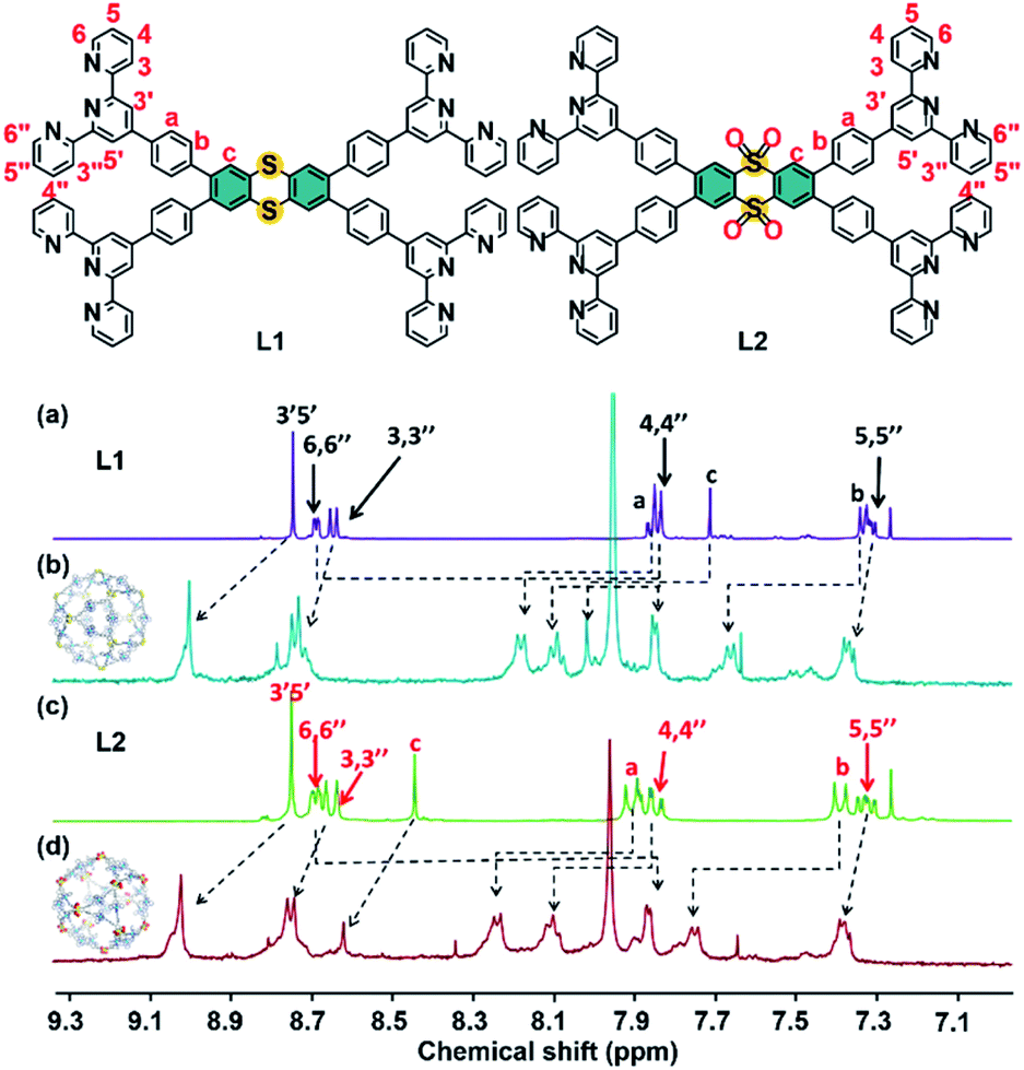
Using terpyridine monomers coordinated with transition metal ions [i.e., <tpy-M2+-tpy> (M = transition metal ion)] as linking units36 and inspired by Archimedean solids, a series of Archimedean-shaped supramolecular cages, such as tetrahedra,37–39 octahedra,40,41 and cuboctahedra,42 were reported. Based on a similar design principle, we report two cuboctahedral-shaped supramolecular cages S1 and S2. The dihedral angles of thianthrene and tetra-oxide thianthrene moieties are about 149° and 144°, respectively, and they decrease to 125° to form a cuboctahedron during coordination with Zn2+. L1 and L2 are prepared by the Suzuki coupling reaction of 2,3,7,8-tetrabromothianthrene and 2,3,7,8-tetrabromothianthrene-5,5,10,10-tetraoxide with 4-(2,2′:6′2′-terpyridine) phenylboronic acid (Schemes 1 and S1, ESI†). Afterward, ligand L1 or L2 is assembled with Zn(NTf2)2 at a precise stoichiometric ratio of 1![[thin space (1/6-em)]](https://www.rsc.org/images/entities/char_2009.gif) :2 in CHCl3/MeOH (1:1, v/v) at 55 °C for 8 h. The precipitates S1 and S2 are obtained by adding an excess amount of LiNTf2 into the mixture and purifying it by repeated washing with deionized H2O and MeOH. In the 1H NMR spectra of S1 and S2, a single set of peaks is observed, indicating the formation of a single and highly symmetric species. The signals in the 1H NMR spectrum are assigned with the aid of 2D 1H–1H COSY and 2D 1H–1H NOESY NMR (Fig. S5, S6 and S10, S11, ESI†). As shown in Fig. 1, except for the signal corresponding to 6,6′′-tpy hydrogen atoms, the signals of other hydrogen atoms are shifted downfield in the complexes. The upfield shift of 6,6′′-tpy hydrogen atoms (from 8.68 ppm to 7.85 ppm) is indicative of the formation of the pseudo-octahedral bister pyridinyl complex moieties. Diffusion-ordered NMR spectroscopy (DOSY) provides dimensional information on S1 and S2, as shown in Fig. S13 and S14.† The DOSY spectra of S1 and S2 show a narrow band of signals with a diffusion coefficient (D) around 9.55 × 10⁻¹¹ and 8.91 × 10⁻¹¹ m2 s−1, indicating the presence of a single species in the solution, separately. According to the Stokes–Einstein equation, the calculated radii of the spherical complexes are 5.44 and 5.82 nm, which were fitted in with the sizes obtained by molecular modeling (5.63 nm and 5.90 nm).
:2 in CHCl3/MeOH (1:1, v/v) at 55 °C for 8 h. The precipitates S1 and S2 are obtained by adding an excess amount of LiNTf2 into the mixture and purifying it by repeated washing with deionized H2O and MeOH. In the 1H NMR spectra of S1 and S2, a single set of peaks is observed, indicating the formation of a single and highly symmetric species. The signals in the 1H NMR spectrum are assigned with the aid of 2D 1H–1H COSY and 2D 1H–1H NOESY NMR (Fig. S5, S6 and S10, S11, ESI†). As shown in Fig. 1, except for the signal corresponding to 6,6′′-tpy hydrogen atoms, the signals of other hydrogen atoms are shifted downfield in the complexes. The upfield shift of 6,6′′-tpy hydrogen atoms (from 8.68 ppm to 7.85 ppm) is indicative of the formation of the pseudo-octahedral bister pyridinyl complex moieties. Diffusion-ordered NMR spectroscopy (DOSY) provides dimensional information on S1 and S2, as shown in Fig. S13 and S14.† The DOSY spectra of S1 and S2 show a narrow band of signals with a diffusion coefficient (D) around 9.55 × 10⁻¹¹ and 8.91 × 10⁻¹¹ m2 s−1, indicating the presence of a single species in the solution, separately. According to the Stokes–Einstein equation, the calculated radii of the spherical complexes are 5.44 and 5.82 nm, which were fitted in with the sizes obtained by molecular modeling (5.63 nm and 5.90 nm).
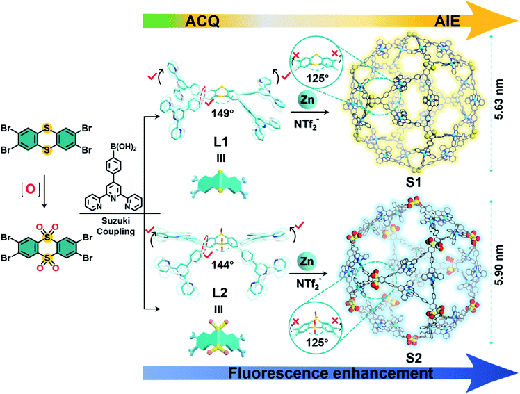 |
| | Scheme 1 Preparation of cuboctahedra S1 and S2 by the self-assembly of L1, L2, and Zn2+. [The structures of L1 and L2 are the X-ray single-crystal structures (C = cyan, O = red, N = blue, S = yellow); hydrogen, and solvents were omitted for clarity; the structures of S1, S2 represent optimized molecular model structures]. | |
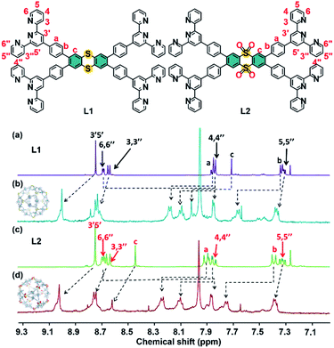 |
| | Fig. 1
1H NMR spectra (500 MHz, 298 K) of (a) L1, (c) L2 in CDCl3 and (b) S1, (d) S2 in CD3CN:DMF-d7 (4:1, v/v). | |
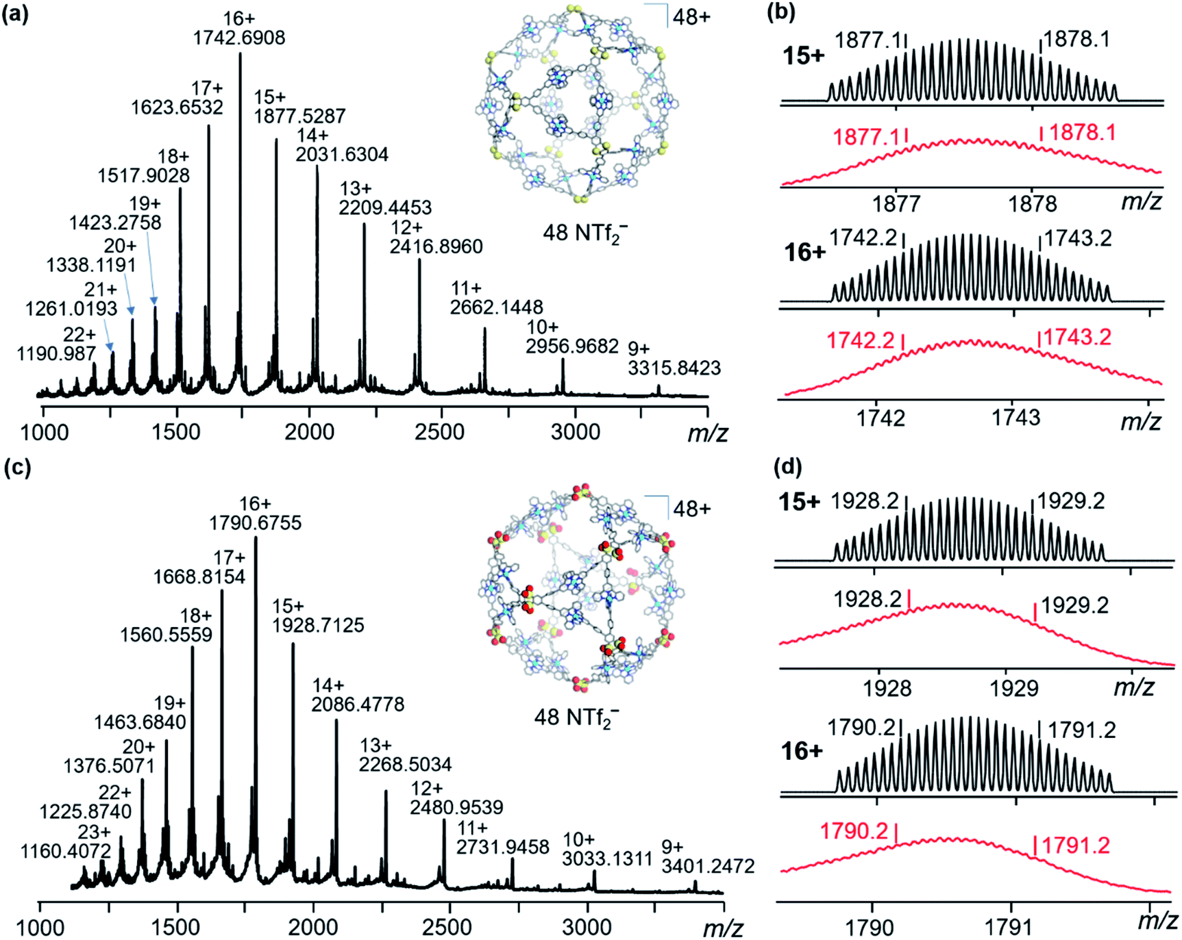
Furthermore, multidimensional mass spectrometric techniques, including ESI-MS, traveling wave ion mobility mass spectrometry (TWIM-MS), and gradient tandem mass spectrometry (gMS2), provide further evidence for the formation of an accepted discrete assembly. In Fig. 2a and c, the S1 solution shows one dominant set of peaks with continuous charge states from 9+ to 22+, and S2 shows signals ranging from 9+ to 23+. After deconvolution of m/z, the average measured molecular mass of the assembly is 32364 Da [(C96H60N12S2)12Zn24(C2F6NO4S2)48] and 33132 Da [(C96H60N12S2O4)12Zn24(C2F6NO4S2)48], which agrees with the molecular composition of S1 and S2. The experimental isotope patterns of each charge state (Fig. 2b and d) are consistent with the theoretical simulations. The TWIM-MS experiment separates the ions based on the size/shape and charge.43 The TWIM-MS spectra exhibit a single band of signals with charge states of 12+ to 23+ for S1 and charge states of 10+ to 23+ for S2, indicative of a single species existing in the solution for both complexes (Fig. S21, ESI†). gMS2 experiments were performed on the 17+ ions at m/z of 1623.7 and 1668.8 by collision-induced dissociation with collision energies ranging from 4 to 43 V (Fig. S24 and S25, ESI†). S1 dissociates at 41 V, while S2 dissociates at 43 V, exhibiting lower stability than S1 in the gas phase.
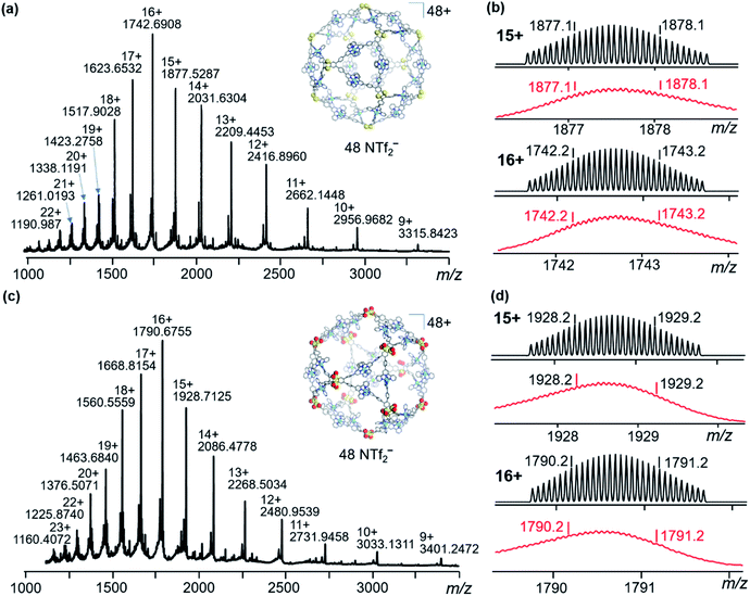 |
| | Fig. 2 ESI-MS spectra of (a) S1 and (c) S2; isotopic patterns of two charge states for (b) S1 and (d) S2. Top: the calculated value, bottom: the experimental value. | |
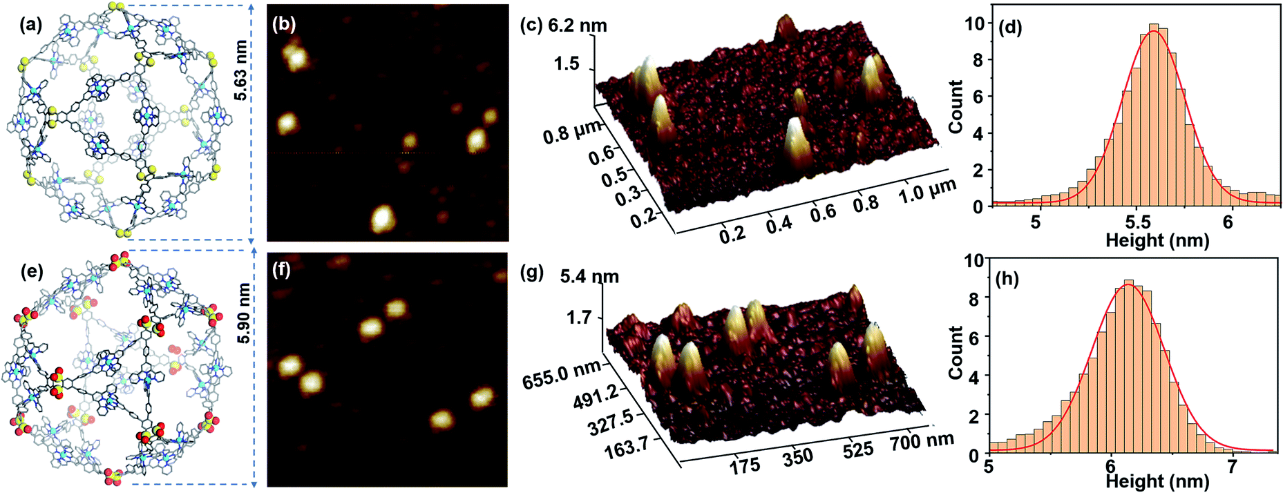
Transmission electron microscopy (TEM) facilitates the visualization of the cuboctahedra for S1 and S2, by directly revealing both the shape and the size of individual molecules. The TEM images are obtained by depositing the DMF solutions of complexes (2 × 10⁻⁶ M) on a carbon-coated copper grid (Cu, 400 mesh), concentrating the complexes upon evaporation of the solvent before inserting the grid into the TEM under vacuum (Fig. S32 and S33, ESI†). The outlines of single molecules located on the films with edges and corners can be observed, with a diameter of 5.70 nm and 6.10 nm. Moreover, the average distance between the two edges perfectly fits the diameter of 5.63 nm and 5.90 nm which was obtained from the optimized molecular model for S1 and S2. The atomic force microscopy (AFM) images of S1 and S2 are also obtained on freshly cleaved mica surfaces (Fig. 3b and f). According to the statistical height histogram for 100 particles from the AFM images (Fig. 3d and h), most dots have the same diameter as the theoretical predicted ones. Furthermore, Fig. 3c and g show that the observed heights of S1 and S2 are mostly 5.71 nm and 6.15 nm, matching the expected structures.
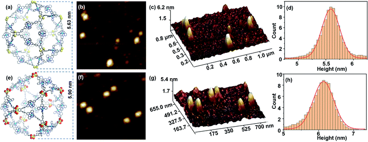 |
| | Fig. 3 AFM images of S1 and S2. (a) and (e) representative energy-minimized structure from molecular modelling of S1 and S2, (b) and (f) AFM images of S1 and S2; (c) and (g) 3D AFM images of S1 and S2; (d) and (h) height statistical histogram of AFM for 100 particles of S1 and S2. | |
ACQ effects of ligands and AIE effects of supramolecules
S1 and S2 exhibit extraordinary AIE effects, uncommon among coordination-driven supramolecules.44,45 Firstly, L1 shows weak emission at 550 nm in CHCl3, while L2 exhibits strong emission at 430 nm caused by the over-oxidation of the electron-donating S atom to electron-withdrawing sulphone46,47 (Fig. S39, ESI†). Similarly, S1 exhibits very weak yellow luminescence at 580 nm in the DMF solution, while the strongest emission peak of S2 is blue-shifted to 450 nm. Considering the solubility and aggregation state of ligands and supramolecules, we chose the mixtures of CHCl3/methanol and DMF/H2O as good and poor solvents (Fig. S40, S43 and S44, ESI†), respectively, to perform the studies.
As depicted in Fig. 4a, when the methanol content is 10–20%, the fluorescence intensity of L1 is enhanced with the slightly redshifted wavelength. The ligand L1 demonstrates a typical ACQ effect (Fig. 4g), accompanied by a considerable decrease in photoluminescence intensity (Fig. 4a and c) (ΦF < 5%) as the methanol content gradually increases. According to the single-crystal structure of L1, at high concentrations, there exist π–π interactions between L1 molecules, and the excited high-energy molecules lose most of their energy through close contact thus weakening the luminescence. Furthermore, as can be seen from the CIE (Fig. 4e), the change in the L1 fluorescence is also consistent with the one in Fig. 4g. L2 also exhibits the same phenomenon compared with L1; the maximum fluorescence quantum yield is 65% at a methanol content of 50% (Fig. 4b and d), which is the best aggregation state. When the methanol content was 0–50%, L2 shows a significant aggregation-induced emission, which contributes to the enhanced L2 fluorescence intensity. It is attributed to the enhanced interactions between the L2 molecules and the restricted bending and vibration of the thianthrene moiety. When the methanol content exceeds 50%, the ACQ and AIE effects combine to reduce the overall fluorescence intensity of L2.20,48 An explanation for this phenomenon is that L2 still has the typical ACQ effect, where collisions of molecules at high concentrations lead to a partial loss of energy with increase in the undesirable solvent, resulting in the weakening of the fluorescence intensity.
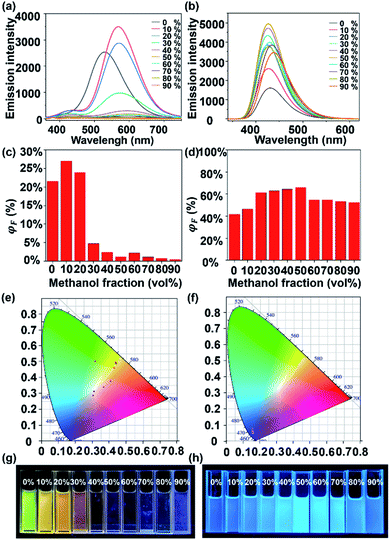 |
| | Fig. 4 ACQ of L1 and AIE of L2. (a) and (b) fluorescence spectrum (λex = 340 nm, c = 1.0 μM), (c) and (d) quantum yields, (e) and (f) CIE 1931 chromaticity diagram (the crosses signify the luminescence color coordinates), (g) and (h) photographs of L1 and L2 in CHCl3/CH3OH with various methanol contents. | |
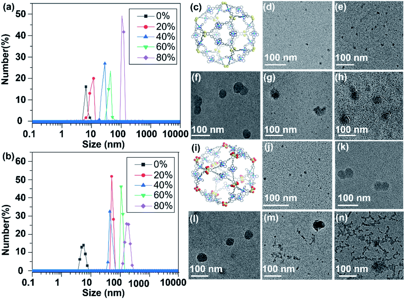
In sharp contrast to L1, cage S1 shows an AIE effect, which displays gradually enhanced ΦF as the H2O content increases, i.e., from 3.7% with 0% H2O to 7.6% with 50% H2O (Fig. 5c). In Fig. 5a, when the H2O content is 40%, the aggregation of S1 reaches a certain level, and the vibrational bending of the thianthrene group is gradually limited when the AIE starts to dominate. With the H2O content reaching 50%, the ΦF of S1 is 7.6%. As the H2O proportion increases, the fluorescence intensity begins to decrease because the tight arrangement of the supramolecules increases the intramolecular collisions, which leads to energy loss. A similar phenomenon can be seen in Fig. 5e; when the H2O content keeps increasing, the emission of S1 mainly concentrates on the yellow light region. The TEM and dynamic light scattering (DLS) results also provide evidence for this phenomenon. From Fig. 6d–h it can be seen that S1 aggregated into nanosphere particles in DMF/H2O, whose size gradually increases with the H2O content (from 5.7 nm to 61 nm). When S1 is stacked into a nanospherical structure, the intermolecular spacing is reduced, limiting the vibration of the molecules, and leading to the appearance of the AIE phenomenon (Fig. 5g).
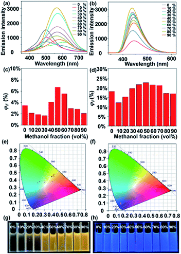 |
| | Fig. 5 AIE of S1 and S2. (a) and (b) fluorescence spectrum (λex = 340 nm, c = 1.0 μM), (c) and (d) quantum yields, (e) and (f) CIE 1931 chromaticity diagram (the crosses signify the luminescence color coordinates), (g) and (h) photographs of S1 and S2 in DMF/H2O with various H2O contents. | |
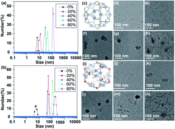 |
| | Fig. 6 TEM images and dynamic light scattering (DLS) of S1 and S2 aggregates. (a) and (b) size distributions of S1 and S2 in DMF/H2O mixtures determined by DLS (the percentages in the graphs are the poor solvent contents); (c) and (i) representative energy-minimized structure from the molecular modeling of S1 and S2. TEM images of S1 and S2 in DMF/H2O mixtures containing (d) and (j) 0%, (e) and (k) 20%, (f) and (l) 40%, (g) and (m) 60%, (h) and (n) 80% H2O. | |
S2 shows an analogous phenomenon to S1, with a decrease in fluorescence intensity at H2O contents of less than 30% (Fig. 5b). As the H2O content continues to increase, the effect of supramolecular aggregation in the system becomes apparent, with the fluorescence intensity increasing until the H2O content reaches 50% (ΦF = 23.35%) (Fig. 5d). Another interesting phenomenon is that both L2 and S2 show strong blue luminescence. According to the CIE diagram (Fig. 4f and 5f), they are concentrated in the blue region of the standard color, providing a theoretical basis for further applications of supramolecular cages in light-emitting devices. Compared with the TEM results of S1, S2 aggregates into much larger nanospheres when H2O contents are 20% and 40% (about 41 nm and 49 nm, respectively, Fig. 6k and l), and intriguingly, another necklace-like aggregation appears at higher H2O contents (Fig. 6m and n). These results agree with the higher AIE effect observed in S2 than in S1 (Fig. 5a and b), which also suggests that the distribution of ligands and the shape of the structural units are critical for the luminescence of the formed supramolecular structures.
Hierarchical self-assembly of S1 and S2
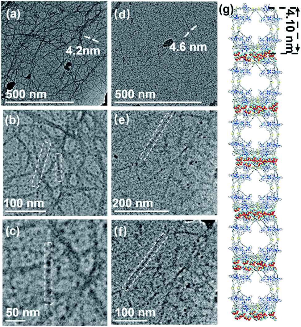
Firstly, all the samples are obtained by diffusing diethyl ether into the complex solution (2 mg mL−1 in DMF). Surprisingly, the one-by-one accumulation of supramolecular cages via directional electrostatic interactions with multiple anions and cationic cages in the fibrous structure can be clearly seen in the TEM images (Fig. 7a–c and S34, ESI†).49 The diameters of nanotubes (4.1 nm) are consistent with the individual supramolecule S1 from the energy-minimized structure. In our previous work, we found that cuboctahedral structures were stacked in square faces through crystal structures,42 so it is assumed that the hierarchical self-assembly of nanofiber structures is packed in the same way (Fig. 7g). In Fig. 7d–f, the formation of fiber-like nanostructures for S2 through the gathering of individual supramolecular structures can also be seen (Fig. S35, ESI†). In addition, according to the change process in Fig. S36,† supramolecular S2 first aggregates to form a nanofibrous structure, then a distinct strip-like structure with further diffusion of diethyl ether, finally aggregating into a sphere. We performed elemental analysis tests on these two parts to demonstrate that the spherical and necklace-like structures were also agglomerated from S2 (Fig. S37 and S38, ESI†). The results show that these two parts contain the same elements as S2 and approximately the same elemental proportions, also providing evidence for our speculation on the formation process of the spherical structure.
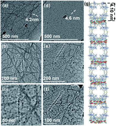 |
| | Fig. 7 Stepwise zoom of the TEM image in the same area of nanofibers assembled by S1 (a–c) and S2 (d–f) (2 mg mL−1 in the DMF solution under ethyl ether vapor) and (g) the probable stacking approaches of S1 (stacking with square surfaces as contact surfaces). | |
Interaction between supramolecular structures and zinc porphyrin
Herein, the initial study using trimethoxy-porphyrin as the guest was conducted. According to the analysis, porphyrins more likely coordinate with the zinc of supramolecules, disrupting the supramolecular structure (Fig. S26, ESI†). Consequently, zinc porphyrins are used for further investigation. We performed the test by dropwise adding the guest molecule (6.0 eq.) dissolved in DMF to the supramolecular solution. The prepared complexes are confirmed by 2D DOSY, ESI-MS, TWIM-MS, gMS2, UV-vis, and fluorescence spectroscopies. Firstly, the DOSY pattern exhibits two narrow signal bands attributed to S1 and zinc porphyrin, indicating the external association due to the weak interactions (Fig. S19, ESI†).50 Three sets of signals belong to free S2 (black), one porphyrin adduct S2⊃G (green), and two porphyrin adducts S2⊃G2 (yellow), respectively, with continuous charge states from 11+ to 21+, in Fig. 8b, consistent with the TWIM-MS spectrum (Fig. 8c). These porphyrin adducts of S2 exhibit unstable and rapid recombination behavior. Once an external voltage is imposed, the porphyrin molecules are slowly released, and when the voltage reaches 30 V, they are completely released, leaving only the cage complex (Fig. 8d). Moreover, as soon as the porphyrin solution is added dropwise, the combination of S2 is achieved, showing no significant change with time (Fig. S30 and S31, ESI†). The applied UV and fluorescence tests on the complexes have also been used to characterize the complexes (Fig. 8e and f). Similar behavior of S1 is further verified by DOSY, ESI-MS, TWIM-MS UV-vis, and fluorescence tests (Fig. S20, S27, S28, S46 and S47, ESI†).
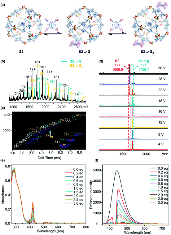 |
| | Fig. 8 (a) External combination of zinc porphyrin with S2; (b) and (c) ESI-MS and TWIM-MS of free S2 (black), one porphyrin adduct S2⊃G (green), two porphyrin adducts S2⊃G2 (yellow); (d) gMS2 of S2⊃G (NTf2−) at m/z 1729.7 with different collision energies; (e) UV-vis spectrum of S2 combining different equivalents of zinc porphyrin (c = 0.5 μM); (f) fluorescence spectrum of S2 combining different equivalents of zinc porphyrin (λex = 340 nm, c = 1.0 μM). | |
Conclusions
A novel design strategy of cuboctahedral-shaped AIE-supramolecular materials has been stumbled upon, providing a novel insight into the design and synthesis of new AIE molecules. The coordination bonds served as the distal inhibition, while the oxygens around sulfur atoms introduced by oxidation served as the proximal inhibition in the atomic clip shape, severely restricting the vibration of thianthrene. Using this protocol, two AIE-supramolecular cages were constructed and characterized by NMR and TWIM-MS, and the related tunable fluorescence properties were studied by fluorescence spectrophotometry, TEM and DLS. Both S1 and S2 showed an optimum AIE state in an aggregated concentration at 50%. To gain a deeper insight, we prepared one-by-one stacked nanofiber structures S1 and S2. In addition, the formation of an adduct between supramolecular cages and zinc porphyrins was explored in detail, providing new directions for investigating external or internal interactions between a giant cage and small molecules. Hence, we present new findings for fabricating fluorescent metal cuboctahedra with potential applications in sensing, host chemistry, and tunable luminescent materials.
Data availability
All data, models, and code generated or used during the study appear in the submitted article.
Author contributions
All authors have given approval to the final version of the manuscript. T. X. and Z. Z designed the experiments; Q. B. and Erendra Manandhar completed the synthesis; T. W. carried out the NMR analysis; Q. B. and Z. Z. did the ESI-MS test and data curation; Q. B., Z. Z. and Erendra Manandhar analyzed the experimental data. M. W. and Y. Z. did the fluorescence quantum yield tests; Q. B. and Z. Z. wrote the manuscript. Z. Z., T. X., P. W. and Newkome G. R. edited the manuscript. All the authors discussed the results and commented on and proofread the manuscript.
Conflicts of interest
There are no conflicts to declare.
Acknowledgements
This research was supported by the National Natural Science Foundation of China (21971257 to P. W., 21971048 for T-Z. X and 22101061 to Z. Z.), the Guangdong Natural Science Foundation (2019A1515011358 to Z. Z.), and the Science and Technology Research Project of Guangzhou (202002030257 to Z. Z.). The authors are thankful for the TEM test and the assistance during data collection by the Modern Analysis and Testing Center of Guangzhou University. The authors thank Prof. Baohua Zhang for quantum yield tests. The authors would like to express their gratitude to EditSprings (https://www.editsprings.cn/) for the expert linguistic services provided.
Notes and references
- Y. Hong, J. W. Y. Lam and B. Z. Tang, Chem. Commun., 2009, 29, 4332–4353 RSC.
- Y. Hong, J. W. Y. Lam and B. Z. Tang, Chem. Soc. Rev., 2011, 40, 5361–5388 RSC.
- J. Luo, Z. Xie, J. W. Y. Lam, L. Cheng, H. Chen, C. Qiu, H. S. Kwok, X. Zhan, Y. Liu, D. Zhu and B. Z. Tang, Chem. Commun., 2001, 18, 1740–1741 RSC.
- J. Mei, N. L. C. Leung, R. T. K. Kwok, J. W. Y. Lam and B. Z. Tang, Chem. Rev., 2015, 115, 11718–11940 CAS.
- N. B. Shustova, B. D. McCarthy and M. Dincă, J. Am. Chem. Soc., 2011, 133, 20126–20129 CrossRef CAS PubMed.
-
(a) M. Wang, Y.-R. Zheng, K. Ghosh and P. J. Stang, J. Am. Chem. Soc., 2010, 132, 6282–6283 CrossRef CAS PubMed;
(b) C. Gui, E. Zhao, R. T. K. Kwok, A. C. S. Leung, J. W. Y. Lam, M. Jiang, H. Deng, Y. Cai, W. Zhang, H. Su and B. Z. Tang, Chem. Sci., 2017, 8, 1822–1830 RSC.
-
(a) M. Liu, S. Onchaiya, L. Y. F. Tan, M. A. Haghighatbin, T. Luu, T. C. Owyong, R. Hushiarian, C. F. Hogan, T. A. Smith and Y. Hong, Molecules, 2017, 22, 2148–2164 CrossRef PubMed;
(b) X. Hu, F. Liu, X. Zhang, Z. Zhao and S. Liu, Chem. Sci., 2020, 11, 4779–4785 RSC.
- H. Zhang, B. Zhang, Y. Zhang, Z. Xu, H. Wu, P.-A. Yin, Z. Wang, Z. Zhao, D. Ma and B. Z. Tang, Adv. Funct. Mater., 2020, 30, 2002323–2002332 CrossRef CAS.
-
(a) X. Jiang, H. Gao, X. Zhang, J. Pang, Y. Li, K. Li, Y. Wu, S. Li, J. Zhu, Y. Wei and L. Jiang, Nat. Commun., 2018, 9, 3799–3807 CrossRef PubMed;
(b) S. Ye, T. Tian, J. Christofferson Andrew, S. Erikson, J. Jagielski, Z. Luo, S. Kumar, C.-J. Shih, J.-C. Leroux and Y. Bao, Sci. Adv., 2021, 7, 1794–1807 CrossRef PubMed.
- C. Sun, B. Li, M. Zhao, S. Wang, Z. Lei, L. Lu, H. Zhang, L. Feng, C. Dou, D. Yin, H. Xu, Y. Cheng and F. Zhang, J. Am. Chem. Soc., 2019, 141, 19221–19225 CrossRef CAS PubMed.
- M. Faisal, Y. Hong, J. Liu, Y. Yu, J. W. Y. Lam, A. Qin, P. Lu and B. Z. Tang, Chem.– Eur. J., 2010, 16, 4266–4272 CrossRef CAS PubMed.
- W.-C. Wu, C.-Y. Chen, Y. Tian, S.-H. Jang, Y. Hong, Y. Liu, R. Hu, B. Z. Tang, Y.-T. Lee, C.-T. Chen, W.-C. Chen and A. K. Y. Jen, Adv. Funct. Mater., 2010, 20, 1413–1423 CrossRef CAS.
- X. Cai and B. Liu, Angew. Chem., Int. Ed., 2020, 59, 9868–9886 CrossRef CAS PubMed.
- Z. Ning and H. Tian, Chem. Commun., 2009, 37, 5483–5495 RSC.
- S. J. Toal, K. A. Jones, D. Magde and W. C. Trogler, J. Am. Chem. Soc., 2005, 127, 11661–11665 CrossRef CAS PubMed.
- L.-J. Chen, Y.-Y. Ren, N.-W. Wu, B. Sun, J.-Q. Ma, L. Zhang, H. Tan, M. Liu, X. Li and H.-B. Yang, J. Am. Chem. Soc., 2015, 137, 11725–11735 CrossRef CAS PubMed.
- H.-T. Feng, Y.-X. Yuan, J.-B. Xiong, Y.-S. Zheng and B. Z. Tang, Chem. Soc. Rev., 2018, 47, 7452–7476 RSC.
- G. Li, Z. Zhou, C. Yuan, Z. Guo, Y. Liu, D. Zhao, K. Liu, J. Zhao, H. Tan and X. Yan, Angew. Chem., Int. Ed., 2020, 59, 10013–10017 CrossRef CAS PubMed.
- Y. Okazawa, K. Kondo, M. Akita and M. Yoshizawa, J. Am. Chem. Soc., 2015, 137, 98–101 CrossRef CAS PubMed.
- G.-Q. Yin, H. Wang, X.-Q. Wang, B. Song, L.-J. Chen, L. Wang, X.-Q. Hao, H.-B. Yang and X. Li, Nat. Commun., 2018, 9, 567–575 CrossRef PubMed.
- Z. Zhang, Z. Zhao, Y. Hou, H. Wang, X. Li, G. He and M. Zhang, Angew. Chem., Int. Ed., 2019, 58, 8862–8866 CrossRef CAS PubMed.
- P. P. Neelakandan, A. Jiménez and J. R. Nitschke, Chem. Sci., 2014, 5, 908–915 RSC.
- D. Liu, M. Chen, K. Li, Z. Li, J. Huang, J. Wang, Z. Jiang, Z. Zhang, T. Xie, G. R. Newkome and P. Wang, J. Am. Chem. Soc., 2020, 142, 7987–7994 CrossRef CAS PubMed.
- N. Song, Z. Zhang, P. Liu, Y.-W. Yang, L. Wang, D. Wang and B. Z. Tang, Adv. Mater., 2020, 32, 2004208–2004234 CrossRef CAS PubMed.
- X. Yan, T. R. Cook, P. Wang, F. Huang and P. J. Stang, Nat. Chem., 2015, 7, 342–348 CrossRef CAS PubMed.
- W.-J. Li, X.-Q. Wang, D.-Y. Zhang, Y.-X. Hu, W.-T. Xu, L. Xu, W. Wang and H.-B. Yang, Angew. Chem., Int. Ed., 2021, 60, 18761–18768 CrossRef CAS PubMed.
- J. Mei, Y. Hong, J. W. Y. Lam, A. Qin, Y. Tang and B. Z. Tang, Adv. Mater., 2014, 26, 5429–5479 CrossRef CAS PubMed.
- C. Mu, Z. Zhang, Y. Hou, H. Liu, L. Ma, X. Li, S. Ling, G. He and M. Zhang, Angew. Chem., Int. Ed., 2021, 60, 12293–12297 CrossRef CAS PubMed.
- W. Z. Yuan, P. Lu, S. Chen, J. W. Y. Lam, Z. Wang, Y. Liu, H. S. Kwok, Y. Ma and B. Z. Tang, Adv. Mater., 2010, 22, 2159–2163 CrossRef CAS PubMed.
-
(a) M. Tominaga, K. Suzuki, M. Kawano, T. Kusukawa, T. Ozeki, S. Sakamoto, K. Yamaguchi and M. Fujita, Angew. Chem., Int. Ed., 2004, 43, 5621–5625 CrossRef CAS PubMed;
(b) D. Fujita, Y. Ueda, S. Sato, H. Yokoyama, N. Mizuno, T. Kumasaka and M. Fujita, Chem, 2016, 1, 91–101 CrossRef CAS.
- A. C. Sudik, A. R. Millward, N. W. Ockwig, A. P. Côté, J. Kim and O. M. Yaghi, J. Am. Chem. Soc., 2005, 127, 7110–7118 CrossRef CAS PubMed.
-
(a) M. Pan, W.-M. Liao, S.-Y. Yin, S.-S. Sun and C.-Y. Su, Chem. Rev., 2018, 118, 8889–8935 CrossRef CAS PubMed;
(b) R. A. Bilbeisi, T. K. Ronson and J. R. Nitschke, Angew. Chem., Int. Ed., 2013, 52, 9027–9030 CrossRef CAS PubMed.
- J. Koo, I. Kim, Y. Kim, D. Cho, I.-C. Hwang, R. D. Mukhopadhyay, H. Song, Y. H. Ko, A. Dhamija, H. Lee, W. Hwang, S. Kim, M.-H. Baik and K. Kim, Chem, 2020, 6, 3374–3384 CAS.
- K. Byrne, M. Zubair, N. Zhu, X.-P. Zhou, D. S. Fox, H. Zhang, B. Twamley, M. J. Lennox, T. Düren and W. Schmitt, Nat. Commun., 2017, 8, 15268–15276 CrossRef CAS PubMed.
- M. Pan, W.-M. Liao, S.-Y. Yin, S.-S. Sun and C.-Y. Su, Chem. Rev., 2018, 118, 8889–8935 CrossRef CAS PubMed.
- I. Eryazici, C. N. Moorefield and G. R. Newkome, Chem. Rev., 2008, 108, 1834–1895 CrossRef CAS PubMed.
- C. M. Hong, M. Morimoto, E. A. Kapustin, N. Alzakhem, R. G. Bergman, K. N. Raymond and F. D. Toste, J. Am. Chem. Soc., 2018, 140, 6591–6595 CrossRef CAS PubMed.
- M. Kaphan David, D. Levin Mark, G. Bergman Robert, N. Raymond Kenneth and F. D. Toste, Science, 2015, 350, 1235–1238 CrossRef CAS PubMed.
- T.-Z. Xie, X. Wu, K. J. Endres, Z. Guo, X. Lu, J. Li, E. Manandhar, J. M. Ludlow, C. N. Moorefield, M. J. Saunders, C. Wesdemiotis and G. R. Newkome, J. Am. Chem. Soc., 2017, 139, 15652–15655 CrossRef CAS PubMed.
- T. Wu, Z. Jiang, Q. Bai, Y. Li, S. Mao, H. Yu, L. Wojtas, Z. Tang, M. Chen, Z. Zhang, T.-Z. Xie, M. Wang, X. Li and P. Wang, Chem, 2021, 7, 2429–2441 CAS.
- C. Tan, J. Jiao, Z. Li, Y. Liu, X. Han and Y. Cui, Angew. Chem., Int. Ed., 2018, 57, 2085–2090 CrossRef CAS PubMed.
- T.-Z. Xie, K. Guo, Z. Guo, W.-Y. Gao, L. Wojtas, G.-H. Ning, M. Huang, X. Lu, J.-Y. Li, S.-Y. Liao, Y.-S. Chen, C. N. Moorefield, M. J. Saunders, S. Z. D. Cheng, C. Wesdemiotis and G. R. Newkome, Angew. Chem., Int. Ed., 2015, 54, 9224–9229 CrossRef CAS PubMed.
- Y.-T. Chan, X. Li, J. Yu, G. A. Carri, C. N. Moorefield, G. R. Newkome and C. Wesdemiotis, J. Am. Chem. Soc., 2011, 133, 11967–11976 CrossRef CAS.
- Y. Hou, Z. Zhang, S. Lu, J. Yuan, Q. Zhu, W.-P. Chen, S. Ling, X. Li, Y.-Z. Zheng, K. Zhu and M. Zhang, J. Am. Chem. Soc., 2020, 142, 18763–18768 CrossRef CAS PubMed.
- F. J. Rizzuto, L. K. S. von Krbek and J. R. Nitschke, Nat. Rev. Chem., 2019, 3, 204–222 CrossRef.
- M. J. Aroney, R. J. W. Le Fèvre and J. D. Saxby, J. Chem. Soc., 1965, 571–575 RSC.
- D. Casarini, C. Coluccini, L. Lunazzi and A. Mazzanti, J. Org. Chem., 2006, 71, 6248–6250 CrossRef CAS PubMed.
- M. Zhang, S. Yin, J. Zhang, Z. Zhou, L. Saha Manik, C. Lu and J. Stang Peter, Proc. Natl. Acad. Sci. U.S.A., 2017, 114, 3044–3049 CrossRef CAS PubMed.
-
(a) E. Raee, Y. Yang and T. Liu, Giant, 2021, 5, 100050–100068 CrossRef CAS;
(b) Y. Wang, Y. Sun, P. Shi, M. M. Sartin, X. Lin, P. Zhang, H. Fang, P. Peng, Z. Tian and X. Cao, Chem. Sci., 2019, 10, 8076–8082 RSC.
- G. Wu, Y. Chen, S. Fang, L. Tong, L. Shen, C. Ge, Y. Pan, X. Shi and H. Li, Angew. Chem., Int. Ed., 2021, 60, 16594–16599 CrossRef CAS PubMed.
Footnotes |
| † Electronic supplementary information (ESI) available. CCDC 2132604 and 2132525. For ESI and crystallographic data in CIF or other electronic format see https://doi.org/10.1039/d2sc00082b |
| ‡ These authors contributed equally to this work. |
|
| This journal is © The Royal Society of Chemistry 2022 |
Click here to see how this site uses Cookies. View our privacy policy here. 
 Open Access Article
 This Open Access Article is licensed under a Creative Commons Attribution-Non Commercial 3.0 Unported Licence
 b,
Liao-Yuan
Yao
b,
Liao-Yuan
Yao