
Automated optimization under dynamic flow conditions†
Jonathan P.
McMullen‡
 * and
Brian M.
Wyvratt‡
*
* and
Brian M.
Wyvratt‡
*
Merck & Co., Inc., 26 East Lincoln Avenue, Rahway, NJ 07065, USA. E-mail: jonathan.mcmullen@merck.com; brian.wyvratt@merck.com
First published on 7th October 2022
Abstract
Automated optimization in flow reactors is a technology that continues to gain interest in academic and industrial research. For drug substance applications, where limited material is available for extensive studies, it is imperative that the automated optimization procedure identify ideal conditions for manufacturing in a resource sparing manner. It is equally as important that these investigations provide data-rich results so that the information can be used for process understanding. Achieving these two objectives in parallel is challenging with traditional automated optimization systems that rely on steady-state data. Dynamic flow systems, which adjust process inputs in a controlled manner to collect transient reaction results, maximize reaction information content. In this work, the gains in reaction knowledge by performing the automated optimization in a dynamic flow system are demonstrated using a nucleophilic aromatic substitution as a case study. A gradient-based search algorithm is used to optimize a multi-faceted objective function that accounts for yield, material input, and productivity. The immense dataset from the automated dynamic optimization was used to establish a reaction model to provide greater insight to the reaction kinetics and selectivity.
Introduction
Flow chemistry and continuous reactors have proven to be enabling technologies for pharmaceutical reaction development and drug substance manufacturing.1–5 For process development, the ability to perform experiments in rapid, sequential order has rendered flow reactors powerful tools for reaction optimization.6–10 In flow reactors, where new experimental conditions can be achieved simply by adjusting flow rates or temperature, one factor at a time (OFAT) techniques can be used to individually select the residence time, reagent equivalents, or catalyst loading to achieve a desired reaction outcome.11–13 This strategy can be extended to multiple factors and used to explicitly enumerate the reaction performance over a defined design space.14,15 While these approaches provide results that are easy to visualize, a more insightful and statistically relevant approach toward reaction optimization can be achieved by applying a design of experiment strategy to flow experiments.16 Factorial designs offer reaction sensitivity information and suggest how factors should be adjusted to improve reaction performance. As one nears the optimum, central composite designs are used to approximate the reaction response surface as a quadratic model with the proposed optimal conditions located at the model's supremum. Each of these optimization methodologies described above are iterative, where data from the prior flow experiments are used to update experimental conditions in search of the optimal conditions. As such, the reaction optimization procedure becomes laborious and increasingly complex as the number of process variables grows.The speed and efficiency of these optimization studies can be greatly enhanced with automated optimization flow systems. Here, the reactor system is equipped with process analytical technology (PAT) for reaction monitoring, automation technology to adjust reaction conditions, and a feedback algorithm to guide sequential experiments toward the optimal conditions. Early examples of this technology focused on self-optimization of single-step reactions using black-box optimization algorithms.17–20 Growing interest in flow chemistry research and applications, along with advancements in machine learning,21,22 have led to the expansion of automated optimization systems.23 Besides optimizing the continuous variables of complex reactions,24 discrete optimization approaches have been used to identify the best solvent,25 base,26 and catalyst10,27 for reactions. By cascading flow reactors and including work-up modules in the flow system, automated systems have been used to optimize the conditions for an overall process of a multi-step synthesis.28,29
All automated optimization flow reactor systems require accurate and informative experimental data to arrive at the optimal conditions. Due to limited availability of starting materials, converging on the optimal conditions in a minimum number of experiments is imperative for drug substance process development. A judicious selection among the myriad of algorithms that have been implemented in automated optimization systems can improve efficiency of the optimization investigations,30 though this decision is also influenced by the number of variables, the constraints on the reaction system, accuracy of analytical methods, and prior knowledge of the reaction kinetics. Additionally, because the procedure is material intensive, it is unlikely that multiple automated optimization trials will be performed during development; therefore, the obtained solution must account for all important reaction features, such as yield, purity, and sustainability. Using a multi-faceted objective function, implementing an algorithm that can optimize multiple objective functions simultaneously, or using a model-based optimization approach31,32 ensures superior utility of the optimization results. When these techniques cannot be used directly, it is important that the automated optimization provide sufficient data to generate accurate process models in post-run processing. These models can be used to predict reaction performance, to aid in process characterization experiments, and to identify the appropriate design space for manufacturing.
Despite advancements in the efficiency of automated optimization, these systems have continued to rely on steady-state experiments. This data is collected inefficiently because the reaction material that exits the reactor as the flow systems transitions from one experiment to the next, approximately three to five reactor volumes, is discarded. Dynamic flow systems, on the other hand, have proven to be a data-rich alternative to conventional steady-state approaches by adjusting reaction inputs in a controlled manner to collect transient data.33–36 In these dynamic systems, experimental information content is maximized as each element of the reaction outlet stream provides a new reaction data point. Linear, one-dimensional dynamic experiments, where a single variable is ramped, have shown to be efficient tools for kinetic studies.37 More recent work has illustrated increased efficiency by performing orthogonal 2-dimensional dynamic experiments.38 Multi-dimensional trajectories that combine linear and non-linear ramps have shown to yield higher levels of data density by efficiently transgressing large areas of the reaction design space.39,40
In this work, the enhancement in data-rich experimentation from a dynamic flow system is demonstrated for an automated optimization application. The aromatic nucleophilic substitution (SNAr) shown in Scheme 1 was selected as a case study.41 Features of this reaction are common in drug substance applications, such as the parallel side reaction and the product degradation pathway. Here, the desired product (2) is the ortho-nitro addition of morpholine. The para-nitro isomer (3) and the overreaction double addition product (4) are considered impurities. To further relate this model chemistry to drug substance applications, a hypothetical scenario was created where the reaction was required to produce less than 5.0 LCAP42 of the double addition impurity to generate acceptable quality material, mimicking situations with limited downstream purge capability. A conjugate gradient method was used to optimize an objective function that considered reaction yield, double addition impurity level, process mass intensity, and residence time. The dynamic optimization was performed from two initial conditions to better understand if the global optimum was achieved. Data from these investigations were used to estimate kinetic parameters from a mechanistic model to provide further process insight and map the design space.
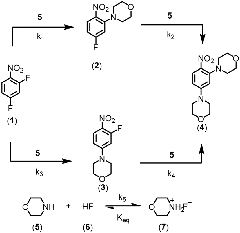 | ||
| Scheme 1 SNAr reaction between 2,4-difluoronitrobenzene and morpholine. | ||
Equipment & experimental methods
Reactor setup
The flow platform (Fig. 1) utilized in this work was designed to be reaction agnostic to afford flexibility for future applications. Substrate and reagent solutions were positioned on Mettler Toledo balances (ME4301) to monitor solution feed rates. The reactor system had three inlet feed streams that were preheated with heat exchangers, and a quench stream that entered downstream of the FTIR. Solutions were charged to the flow reactor using a manifold of high-pressure MilliGAT HF pumps (MG-2-CER-XT-NM, PTFE stator) via tubular heat exchangers (0.04′′ ID PFA, 25 ft, 6.2 mL each) that were submerged in a bath held at 75 °C. The substrate stream (1) was mixed with the solvent stream using a tee-mixer (IDEX, PEEK, 0.050′′ ID, 1/8′′) and then immediately combined with the morpholine stream using an interdigital mixer (MiChS Co., LTD.) before entering the reactor (0.04′′ ID PFA, 12.36 mL). Residence time distribution studies for this reactor have been reported previously.40 The reactor temperature was controlled using a Polar Bear Plus (Cambridge Reactor Design) equipped with custom metal mandrals to secure the reactor, promote heat transfer, and improve experimental reproducibility. In-line monitoring of the reactor outlet stream was achieved with a Fourier transform infrared spectroscopy (FTIR, Mettler Toledo ReactIR 702 L, D-Sub Micro Flow Cell DiComp). The reaction was quenched with a trifluoroacetic acid stream in a Y-mixer (IDEX, PEEK, 0.040′′ ID, 1/8′′) prior to flowing through the fraction collector (Teledyne Isco Foxy R1) where off-line samples were obtained and analyzed using ultra high pressure liquid chromatography (UPLC, Agilent 1290 Infinity II). Check valves (IDEX, 3 psi, 0.020′′ ID, 1/8′′) were leveraged between the FTIR and quench mixer to prevent backflow.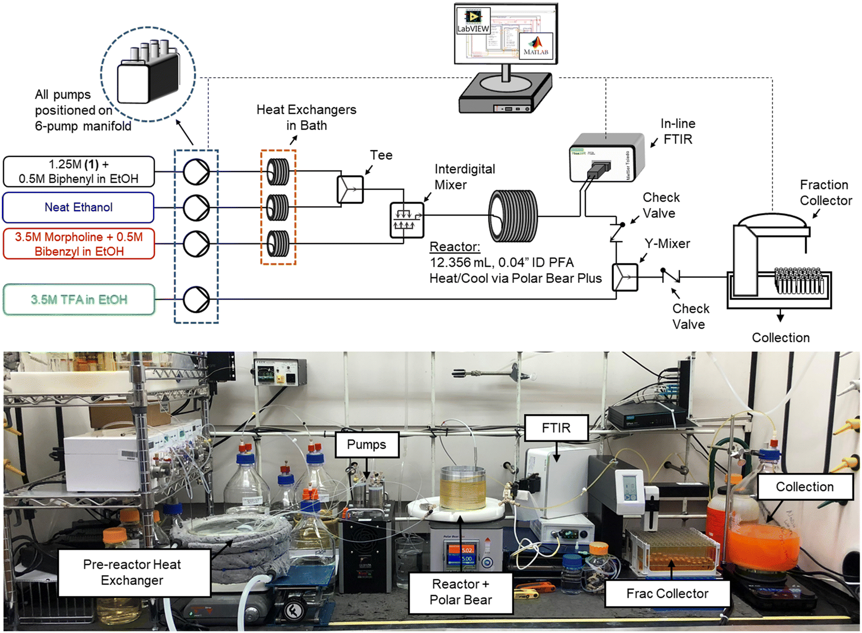 | ||
| Fig. 1 Reactor schematic and picture of reactor in operation. | ||
Reactor automation
LabVIEW (National Instruments, 2018 SP1 Full Developer Suite) was used to automate the reactor platform, leveraging a state machine architecture from JKI (2018). LabVIEW-Matlab interfacing capabilities and the Open Platform Communications Unified Architecture (OPC UA) toolkit were utilized for various aspects of the automation sequence, optimization algorithm, and in-line analytics. New LabVIEW subVIs were generated or existing product architecture was leveraged to control the analytical balances, milliGAT pumps, Polar Bear Plus, and Foxy R1 fraction collector. Additionally, OPC UA functionality was leveraged to read data from the FTIR spectrometer for model regressions and optimization searches to evaluate performance in real-time. Additional details are provided in the ESI.†Analytical methods
To maximize data capture for a single experiment, both in-line analysis (FTIR) and off-line analysis (UPLC) were performed to provide orthogonal datasets for comparison and validation. The fraction collector used repeated fixed time intervals, specified at the start of the experiment for sample collection and diversion to waste. As discussed in previous work,40 to avoid averaging a broad range of dynamic reaction data, a so-called sampling bias, and associated decreased efficiency in data collection, it is recommended to sample based on time rather than by volume. UPLC analyses were performed on an Agilent 1290 Infinity II using an analytical method from previously reported work40 that was leveraged and modified as a fit-for-purpose method for the SNAr chemistry investigated here. Additional details around sample preparation, method parameters, calibrations and analysis are provided in the ESI.†Infrared (IR) spectra were analyzed in the MettlerToledo iC IR software environment (version 7.1). Off-line UPLC results were used to calibrate the FTIR data to train and validate a quantitative model. This predictive model auto-selected the number of factors using spectral information in two regions, 3800–2500 cm−1 and 1800–750 cm−1, due to the ATR bands for diamond.
Experimental conditions & procedure
All experiments were performed in the reactor setup described above. The LabVIEW code required multiple inputs prior to an automated experiment, including the reaction parameters (solution concentrations, the desired reaction concentration, reactor volume) and the optimization parameters, such as the initial point, factor constraints, maximum search step size, and termination criteria. To set the design space, the lower and upper bounds on the residence time (τ) were set to 1 and 20 min, respectively, while the bounds for morpholine equivalents (equiv) were set from 0.5 to 4.0. These design space constraints along with the feasible range of pump flowrates helped to establish the various stock stream concentrations and reactor volume.The stock solutions of 2,4-difluoronitrobenzene and morpholine were prepared at 1.25 M and 3.5 M, respectively, in ethanol. Solutions were prepared in advance of experiments and were found to be stable via HPLC analysis upon extended age. Biphenyl (0.3 M) and bibenzyl (0.4 M) were used as internal standards in the starting material and morpholine streams, respectively, to confirm experimental reaction concentration and morpholine equivalents. To allow residence time and morpholine equivalents to vary independently, a stream of neat ethanol was included, affording an additional degree of freedom to the system. Additionally, to enable accurate offline analysis of the collected fractions, a 3.5 M trifluoroacetic acid (TFA) in ethanol stream was used to quench the reaction downstream of the FTIR, with the TFA equivalents held constant at 4.0 throughout. All reactions were performed at 75 °C. This temperature was selected from a range of values explored in previous works.16,41 Please refer to the ESI† for additional experimental details.
Correction of conditions
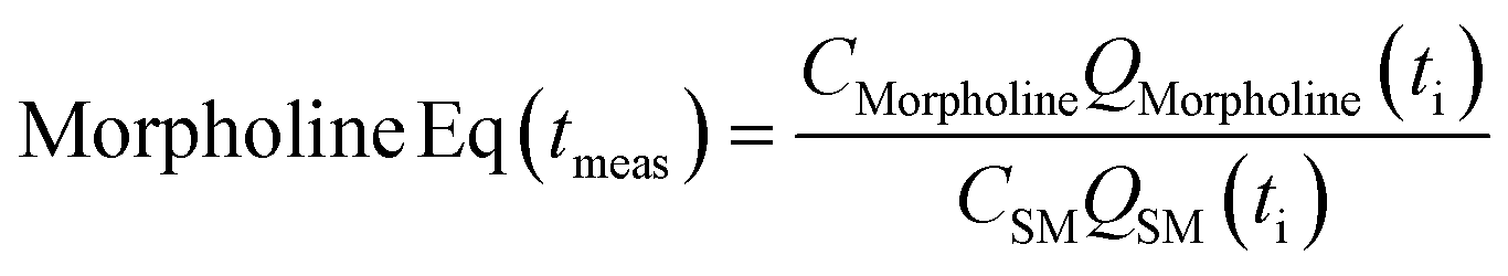
The correct interpretation of experimental results obtained under dynamic flow conditions requires a correlation between the recorded data points as a function of time on stream and the achieved reaction conditions determined by the history of input flowrates. Due to the finite holdup volume of the flow reactor, reaction conditions set at the reactor inlet (e.g., equivalents) as well as the instantaneous residence time based on flowrates are not immediately realized at the reactor effluent. Instead, the actual conditions achieved must be calculated knowing the instantaneous flowrate profile provided as inputs. This correction of experimental conditions is performed for each inline (FTIR) or offline (UPLC) analytical data point to directly correlate reaction results to experienced reaction conditions.The realized residence time for a single reaction element eluting from the reactor is calculated from eqn (1), where Q(t) is the flowrate profile, VReactor is the total reactor volume, and ti and tf are the initial and final reaction time, respectively. The residence time, τ, is then defined as the difference between the final and initial reaction times, as expressed in eqn (2).
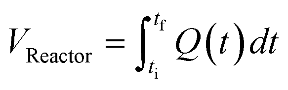 | (1) |
| τ = tf − ti | (2) |
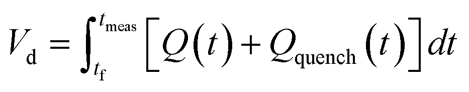 | (3) |
 | (4) |
Optimization methodology & results
Optimization strategy and objective function definition
The optimization strategy was assembled through preliminary dynamic experiments, consideration for real-time reaction monitoring capability, and elements of process development that are typically important to drug substance manufacturing. First, the process variables for reaction optimization were identified and limited to residence time and morpholine equivalents for this SNAr case study. Although temperature is often included in optimization studies, dynamic trajectories in temperature can be challenging as correcting the experimental conditions requires a temperature-dependent kinetic model a priori,38 or a sluggish trajectory to accurately estimate the reaction temperature experienced in the dynamic experiment.39 Because the focus of this work revolves around increasing data-density of automated optimization systems and minimizing resource requirements, it was decided to not include reaction temperature in this initial demonstration.Next, preliminary one-dimensional dynamic flow experiments were performed to characterize reaction performance over the design space and correlate results to process parameters. These initial experiments also provided an appreciation for data reproducibility and were used in the calibration of the FTIR model. Two experiments dynamically varied residence time from 1 to 20 minutes at morpholine equivalents of 2.0 and 3.5, while a third experiment dynamically varied morpholine equivalents from 0.25 to 4.0 at a constant residence time of five minutes. The dynamic transient time (60 min), temperature (75 °C), and sampling strategy (one FTIR scan and one UPLC sample per minute) were held constant in each run. During these dynamic experiments, the in-line FTIR recorded spectra of the reactor outlet stream while the fraction collector aliquoted quenched reaction samples for off-line UPLC analysis. During post-run processing, the reaction conditions corresponding to each acquired data point were corrected using eqn (1)–(4), enabling accurate correlation between reaction performance and the two parameters of interest across the design space.
Results for the three one-dimensional dynamic experimental runs are provided in Fig. 2. Of note, over 370 UPLC results were obtained from these three dynamic experiments highlighting the data-density gains associated with this experimental methodology. The reaction profiles for the various experiments are plotted against time on stream (Fig. 2, X-1 plots) and the corrected conditions (Fig. 2, X-2 plots). Experimental reaction data followed the expected trends in conversion and impurity generation with respect to residence time and morpholine equivalents. Excess morpholine results in faster conversion rates to the desired product (2), but generates stability concerns as product degradation and double addition impurity (4) formation occur with increasing residence time. This trend is best viewed in Fig. 2, A-2, where 3.5 equivalents of morpholine resulted in near reaction completion and a product yield of approximately 84%; however, significant quantities of the double addition impurity formed with slightly longer residence times. In aggregate, these dynamic experiments reveal a balance between residence time, morpholine equivalents, yield, and purity.
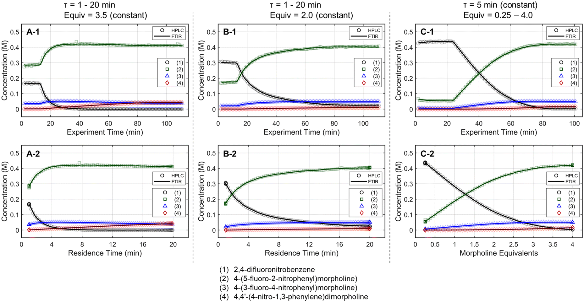 | ||
Fig. 2 One-dimensional dynamic reaction experimental results, showing the FTIR (—) and UPLC (○, , , , , ) results for the various species. The figures portray results from (A-1 and A-2) dynamic residence time (1–20 min) at constant morpholine equivalents (3.5), (B-1 and B-2) dynamic residence time (1–20 min) at constant morpholine equivalents (2.0), and (C-1 and C-2) dynamic equivalents of morpholine (0.25–4.0) at constant residence time (5 min). Plots X-1 represent the reaction performance data as a function of experimental time, while plots X-2 show the reaction performance against the corrected reaction conditions from the 1-dimensional dynamic ramps. ) results for the various species. The figures portray results from (A-1 and A-2) dynamic residence time (1–20 min) at constant morpholine equivalents (3.5), (B-1 and B-2) dynamic residence time (1–20 min) at constant morpholine equivalents (2.0), and (C-1 and C-2) dynamic equivalents of morpholine (0.25–4.0) at constant residence time (5 min). Plots X-1 represent the reaction performance data as a function of experimental time, while plots X-2 show the reaction performance against the corrected reaction conditions from the 1-dimensional dynamic ramps. | ||
The mass balance closure was greater than 97% in all samples, validating the sampling, analytical, and post-processing methods. Experimental reproducibility was assessed by comparing the reaction results at conditions that overlapped across the dynamic trajectories. There was a maximum error of 1.0% in the reaction species concentrations for the duplicate measurements at 2.0 morpholine equivalents and five-minute residence time, and for those at 3.0 equivalents and five-minute residence time. These data reinforce the accuracy and reproducibility of the platform and methodology allowing the work to reliably transition to the automated optimization runs.
These experimental data were also leveraged to calibrate a multivariate, partial least squares (PLS) FTIR model for the main reaction species and the bibenzyl internal standard. FTIR trends for the reaction species derived from the resulting model are provided against the UPLC data results in Fig. 2. Parity plots of measured UPLC concentrations and the model predicted FTIR concentrations are provided in the ESI.† Overall, there was excellent agreement between the FTIR models and the UPLC measurements, giving confidence that the FTIR could be used for accurate real-time reaction monitoring and provide quantitative feedback in the optimization routine.
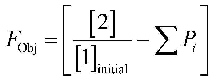
This preliminary knowledge and analytical capability enabled definition of an objective function suitable for many drug substance manufacturing applications. Because comparable reaction performance was observed across different conditions, these experiments suggested that reaction inputs such as residence time and morpholine equivalents could be included in the optimization objective function to search for ideal operating conditions that also achieve target performance. This feature can be important in drug substance manufacturing as multiple aspects, such as process mass intensity, robustness, and cycle time, are considered in addition to yield and purity. Using the objective function (Fobj) defined in eqn (5), the optimization routine aimed to maximize yield while achieving other desired properties through several penalty functions, Pi. Here, piecewise quadratic penalty functions corresponding to P1, P2, and P3 were used to maintain target thresholds on double addition impurity formation, morpholine use, and residence time, respectively. The penalty functions are presented in Fig. 3 with the mathematical formulae given in the ESI.† As common with many optimization routines, the maximization problem was solved by minimizing the negative objective function.
 | (5) |
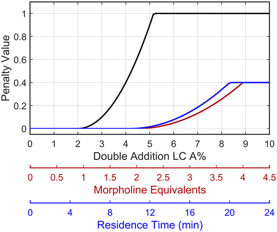 | ||
Fig. 3 Piecewise quadratic penalty functions visualizing the penalty value as a function of double addition impurity levels (—), morpholine equivalents ( ), and residence time ( ), and residence time ( ). ). | ||
Optimization procedure
Given the nature of dynamic flow experiments, where conditions are gradually adjusted to move along a trajectory, a gradient-based optimization approach was deemed the most appropriate to implement in this work. Similar to how numerical solvers perform iterative calculations along a gradient-based search direction to locate the optimum, an automated dynamic flow system continually profiles the reaction along the search trajectory. The paths taken by the gradient-based search also provide a straightforward, visual understanding of the objective function response surface. As such, the optimization procedure provides a solution and an interpretation of the process sensitivities across the search areas. Furthermore, gradient-based search algorithms are typically efficient at finding a local optimum and may minimize the material quantity required to obtain an experimental solution.What follows is the procedure for how a gradient-based search algorithm was applied to dynamic flow experimentation. For reference, a comprehensive flowchart of the approach is provided in Fig. 4.
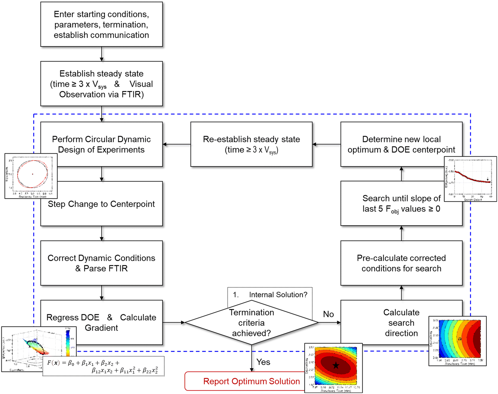 | ||
| Fig. 4 Flowchart describing the optimization algorithm along with associated decision points. Contents within dashed lines represent iterative, automated operations. | ||
Response surface model with transient datasets
Experimentally, gradients are estimated by first fitting a response surface model of the objective function over a subset of the design space and then taking the derivative with respect to the factors. A variety of experimental designs are suitable for this purpose, but factorial and central composite designs are most common in drug substance process characterization. For two-factor designs, a 22 full-factorial design forms a square with experiments performed at the vertices and an experiment at the center to evaluate curvature. While this design is efficient for steady-state experiments, dynamic experiments can better utilize material streams and provide more dense datasets by continuously collecting data along a trajectory that outlines a standard experimental design. While a few continuous function forms were evaluated for establishing a response surface model (see ESI†), a circular path inscribed within the vertices of a 22 factorial design was selected. To evaluate curvature over the local design space, the system underwent a step-change to the center point and collected a single steady-state data point. While this discontinuity in experimental path was undesired as a fully dynamic optimization was pursued, compared to alternative methods considered, this simplistic design offered a straightforward approach to achieving corrected conditions that more closely resembled the intended dynamic design. A more detailed discussion of these dynamic design of experiment patterns and the corresponding corrected conditions are provided in the ESI.†With the dynamic design of experiment structure established, other key parameters governing the operations were defined. The dynamic transient time (tdynamic), defined as the time for dynamic operations, and the reaction residence time center point (τCP) both impact how closely the corrected conditions match the targeted input conditions. Over the course of this work, the ratio tdynamic/τCP was identified as a tuning parameter to balance experimental throughput and roundness of the corrected conditions. Simulations were performed at various tdynamic/τCP values (see ESI†), and a ratio of 15 struck the appropriate balance for this application. Example dynamic design of experiments simulations with a tdynamic/τCP of 15 are provided in Fig. 5, showing the consistency across differing center point and dynamic transient time conditions. Additionally, parameter ranges around the design center point, [τCP, EquivCP], were set at EquivCP ± 0.5 for morpholine equivalents while the range in residence time was variable for each center point expressed as τCP ± 0.25 × τCP. These ranges were selected to ensure a measurable response in both parameters regardless of the center point. Prior to performing the dynamic design of experiments, residence time and equivalents ranges were transformed to coded variables, x1 and x2, respectively, which ranged from −1 to 1. These coded variables were leveraged through the dynamic design of experiments, regression, and gradient calculation; coded variables were then renormalized prior to the search operation.
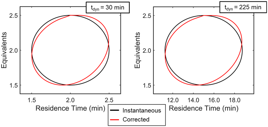 | ||
Fig. 5 Simulation results showing the instantaneous (—) and associated corrected ( ) conditions for two example circular design of experiments centered at [τ, Equiv] = [2 min, 2.0] (left) and [15 min, 2.0] (right). The dynamic transient time, calculated using the tdynamic/τreaction ratio of 15, is shown for each simulation as well. ) conditions for two example circular design of experiments centered at [τ, Equiv] = [2 min, 2.0] (left) and [15 min, 2.0] (right). The dynamic transient time, calculated using the tdynamic/τreaction ratio of 15, is shown for each simulation as well. | ||
The above dynamic design of experiments methodology was implemented in practice in the following manner:
1. Experimental factors [τ, Equiv] were converted to coded factors [x1,x2] using a specified or calculated center point [τCP, EquivCP] and the pre-defined factor ranges.
2. Performed initial steady state experiment at [x1,x2] = [0,1].
3. Dynamically progressed clockwise around the circular design, returning to [x1,x2] = [0,1].
4. Re-equilibrated system at [x1,x2] = [0,1].
5. Performed step change to the center point conditions [x1,x2] = [0,0] and flushed three system volumes to achieve steady-state and obtain reaction performance at center point.
After performing the circular design of experiments and recording reaction results via the inline FTIR, the automated optimization algorithm corrected reaction conditions (eqn (1)–(4)) using the imbedded Matlab code. The yield and penalty functions were evaluated at each corrected condition to calculate the corresponding objective function value. Stepwise linear regression was then used to model the objective function as a quadratic function of the two parameters, corrected residence time and morpholine equivalents, as shown in eqn (6).
| F(x) = β0 + β1x1 + β2x2 + β12x1x2 + β11x21 + β22x22 | (6) |
Before implementing in a fully autonomous optimization, the above protocol was tested in a series of experiments in two different regions of the design space. These validation experiments are provided in the ESI.† Results indicate that the algorithm responsible for the experimental design, data manipulation/transformation, and regression to generate a response model performed adequately. These results not only validate the algorithm to generate a response surface model, but also ensure an accurate gradient is obtained from which to inform a path forward towards the reaction optimum.
Search direction and termination criteria
From the objective function response surface model (eqn (6)), the gradient vector, g(x), can be estimated as the partial derivative with respect to input factors (eqn (7)–(8)).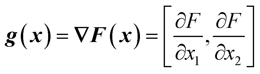 | (7) |
| g(x) = [β1 + β12x2 + 2β11x1, β2 + β12x1 + 2β22x2] | (8) |
In this work, the search direction vector, p(x), was calculated using the Polak-Ribiere conjugate gradient (PR-CG) method. This protocol provides favorable convergence for quadratic cost functions and biases the search direction toward the direction of steepest descent when the cost function is not quadratic.43 As defined by eqn (9)–(10), the PR-CG method leverages objective function trends from the current gradient (gk+1), the previous gradient (gk), and the prior search direction (pk) in calculation of the new search vector to avoid the “zig-zag” behavior in the steepest descent. In these calculations, the gradient of the current iteration, g(x)k+1, is calculated using the current center point, xk+1, and the previous gradient, g(x)k, which was measured at the previous center point, xk.
| pk+1 = g(x)k+1 + γpk | (9) |
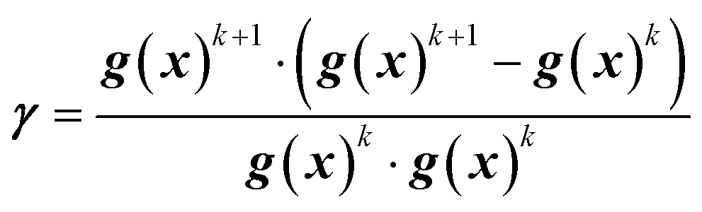 | (10) |
This iterative procedure of performing dynamic design of experiments and line searches continued until the optimal conditions resided within the response surface of the current dynamic design of experiment. These conditions are defined as a point, x*, which lies within the bounds of the current dynamic design of experiment range, has g(x*) = 0, and a positive Hessian, H(x*) > 0. When these conditions are satisfied, the program terminated.
Automated optimization results
Building from the preliminary experimental work and methodology described above, automated dynamic experiments were performed from two initial conditions. The first investigation started with a residence time of 2 minutes and 1.5 morpholine equivalents. These initial conditions achieved incomplete reaction conversion allowing for investigation into how the system would improve the reaction performance while balancing the penalty functions. The second investigation started at a 15 minute residence time and 3.5 equivalents of morpholine. Under these conditions, yield was near maximum levels, but double addition impurity levels were elevated and the penalty functions greatly diminished the objective function value. Here, optimization progress would aid in understanding how the system would move toward preferred operating conditions when final conversion levels were already realized. Additionally, performing these independent experiments provided a sense of system robustness and increased the likelihood of identifying a global optimum. As shown in Table 1, the results from both dynamic optimization investigations converged to an optimum near 10 minutes and ∼2.3 equivalents of morpholine.| Initial conditions | Final conditions | |||||
|---|---|---|---|---|---|---|
| τ (min) | Equiv | F | τ (min) | Equiv | F | |
| a Gradient algorithm operated as a minimizer with more negative responses correlating to more desirable outcomes. | ||||||
| Investigation #1 | 2.0 | 1.5 | −0.36 | 10.2 | 2.39 | −0.77 |
| Investigation #2 | 15.0 | 3.5 | +0.50 | 10.0 | 2.26 | −0.78 |
As the experimental approach was consistent across the two investigative experiments sans the initial conditions, an in-depth dissection of the experimental results is limited to the run initialized at a residence time of two minutes and 1.5 morpholine equivalents (investigation #1); additional details for investigation #2 can be found in the ESI.† In investigation #1, starting with the initial conditions of two minute residence time and 1.5 equivalents, the dynamic flow system continuously adjusted flow rates (Fig. 6A) to tune the residence time and morpholine equivalents (Fig. 6B and C) to improve the reaction performance (Fig. 6D) and objective function (Fig. 6E). Closer inspection of the data reveals that the flow reaction conditions were predominantly dynamic throughout the experiment and operated under steady-state only during the step changes to the center point (Fig. 6A). The corrected conditions (Fig. 6B and C) matched the targeted input conditions due to the well-informed selection of dynamic transient times, as discussed previously. The FTIR model that was used for feedback was further validated through off-line UPLC analysis of collected, quenched samples (Fig. 6D). Overall, the automated dynamic optimization collected 907 FTIR and 302 UPLC data points during its search for the optimal conditions.
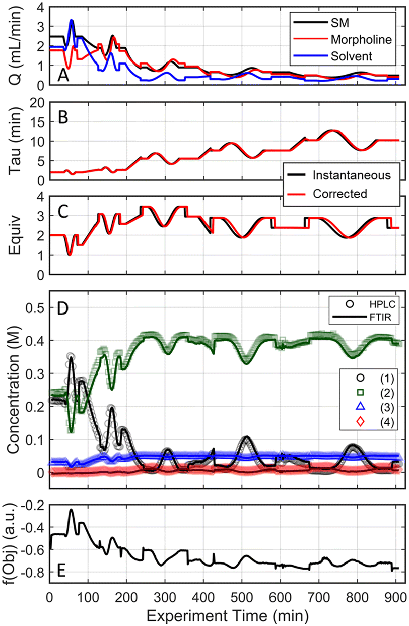 | ||
| Fig. 6 Conditions and experimental results from the automated optimization run starting from [2 min, 1.5 equiv] presented as a function of experimental time on stream. (A) Flowrates for the 3 streams combined to drive the reaction and control conditions: 2,4-difluoronitrobenzene (SM), morpholine (base) and ethanol (solvent). (B and C) Instantaneous/input conditions and subsequently corrected conditions as a function of time on stream. (D) UPLC and FTIR data results for the 4 species: (1) 2,4-difluoronitrobenzene, (2) 4-(5-fluoro-2-nitrophenyl)morpholine), (3) 4-(3-fluoro-4-nitrophenyl)morpholine), (4) 4,4′-(4-nitro-1,3-phenylene)dimorpholine. (E) Calculated objective function based on the FTIR results and corrected conditions as a function of experiment time. | ||
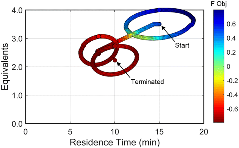
The approach that the automated dynamic optimization system used to arrive at the optimal conditions for the first investigation can be best understood through a series of figures. The procedure began with the dynamic design of experiment around the initial conditions of two minute residence time and 1.5 equivalents of morpholine, corresponding to the circular subset of data surrounding the initial conditions in Fig. 7. Note, the circular dynamic design of experiment generated in coded factors is elongated when plotted with real variables. Stepwise regression was then performed on the objective function output to generate the response surface model (RSM) shown in Fig. 8, RSM #1. The RSM #1 parity plot in Fig. 8 shows the excellent agreement between the experimental objective function values and those predicted by the empirical model. This agreement assures that the optimization algorithm can leverage the response surface model to accurately identify the appropriate search direction.
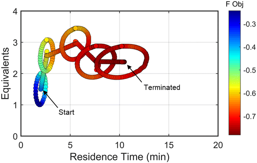 | ||
| Fig. 7 Objective function plotted against the design space conditions for the optimization run starting from [2 min, 1.5 equiv]. | ||
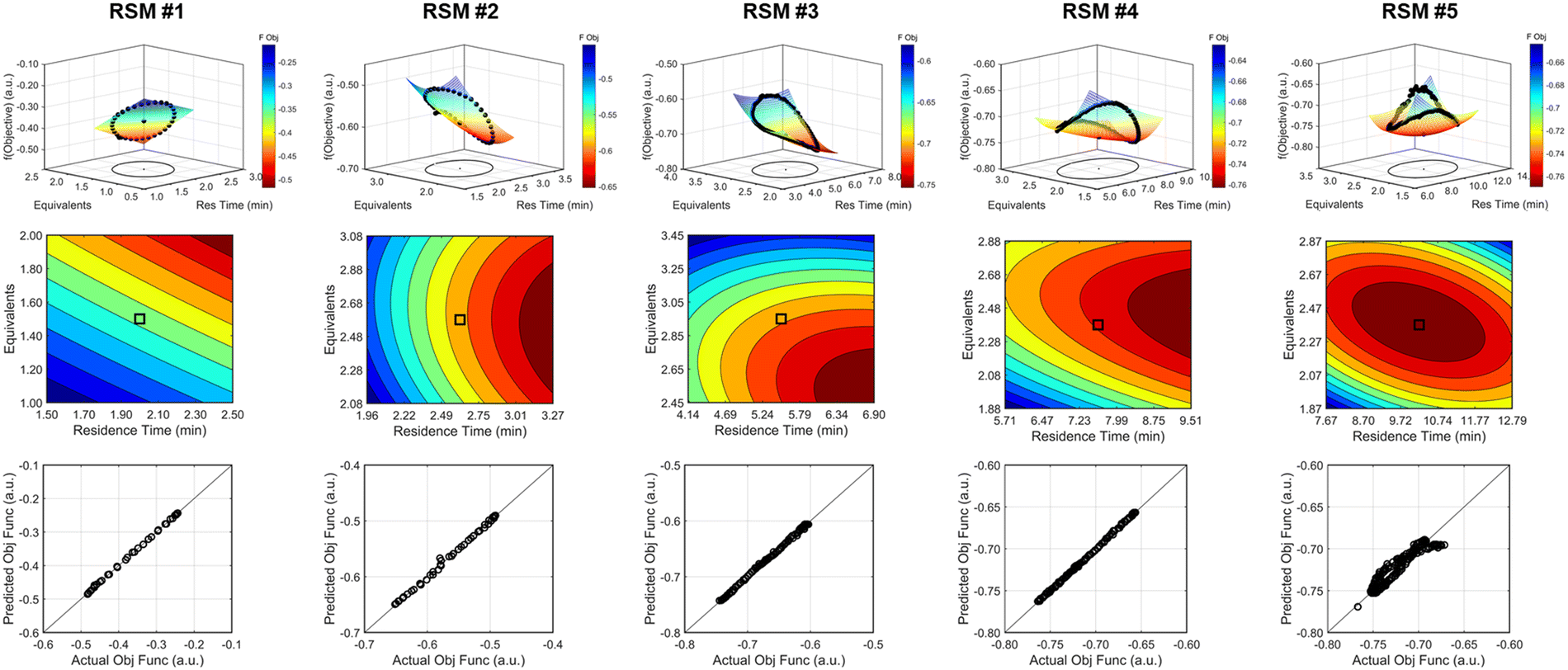 | ||
| Fig. 8 Response surface model results for the various DOEs performed during the investigation #1, the run starting from [τ, Equiv] = [2 min, 1.5 equiv]. Each DOE and regression is represented within each column. (Top row) comparison of the experimental objective function results and the response surface model mesh against the design space region. (Middle row) contour plot describing the response surface model and directionality. (Bottom row) parity plots of the experimental data against the predicted values based on the RSM. Color scale: objective function improves as color transitions from blue to red. | ||
As the contours of RSM #1 illustrate, the gradient in this region of the design space showed that improvements to the objective function could be achieved by increasing morpholine equivalents and residence time. The lack of active penalty functions in this region indicated that this improvement was driven by increased product yield at longer residence time and higher equivalents. For the first dynamic line search, the autonomous optimization procedure used the method of steepest descent to move along the gradient, starting from the center point. In Fig. 7, this search corresponds to the line of dynamic experiments originating from the initial center point. The objective function values obtained during this dynamic search are provided in Fig. 9, Search #1. As this profile shows, significant improvement in the objective function was achieved during this first search and terminated once a series of successive dynamic experiments showed little improvement. Following termination, parsing the search dataset identified new local best conditions of 2.62 minutes residence time and 2.58 equivalents morpholine.
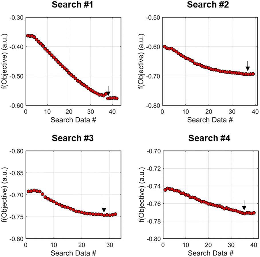 | ||
| Fig. 9 Progression towards minimizing objective function values during the four searches performed during investigation #1, the run starting from [τ, Equiv] = [2 min, 1.5 equiv]. The black arrow in each figure signifies the minimum value throughout the search informing the next dynamic DOE center point conditions chosen. | ||
The second dynamic design of experiment was performed around these new best conditions, resulting in the circular dataset centered around 2.62 minutes residence time and 2.58 equivalents morpholine in Fig. 7. Similar to the operations described above, the algorithm used this data to regress a response surface model (Fig. 8, RSM#2) which also showed excellent agreement with the experimental data (Fig. 8). Here, as in subsequent iterations, the conjugate gradient method was used to calculate the search direction. Consequently, although the gradient in this region suggested that greatest improvement in the objective function would be achieved by increasing residence time alone, information from the prior design of experiments was leveraged to perform a dynamic line search with increasing residence time and equivalents. Objective function values during this dynamic line search are provided in Fig. 9 and correspond to the line of dynamic experiments that originated from 2.62 minutes residence time and 2.58 equivalents morpholine in Fig. 7, ultimately terminating with a new FObj best at 5.52 minutes residence time and 2.95 equivalents morpholine.
The autonomous system continued these iterative operations of dynamic design of experiments and subsequent conjugate gradient line searches for three more iterations. During these later optimization experiments, the penalty functions became active and steered the dynamic routine toward high yielding conditions with more desirable operating conditions. In the last dynamic design of experiments enveloping 10.23 minutes and 2.37 equivalents, the response surface model exhibited curvature with a calculated root within the space explored (Fig. 8, RSM#5). After verifying the response surface model had a positive definite Hessian, the algorithm concluded that the calculated root was indeed an optimum and terminated. Under these conditions, the reaction achieved a 78% yield and a double addition impurity level of 1.2 area% with ∼8% residual starting material and ∼10% side-product impurity present. Additional detail regarding the response surface models terms, gradient vectors and search vectors can be found in the ESI.†
Using similar operations, a second automated optimization (investigation #2) was performed starting at a residence time of 15 min and 3.5 morpholine equivalents (see the results in Fig. 10). Additional details and data for this investigation can be found in the ESI.† In contrast to the previous optimization run, the dynamic design of experiment in this initial region captured product and isomer overreaction to the double addition impurity. Consequently, objective function values in this region were heavily penalized for double addition impurity levels as well as excessive values of morpholine equivalents and residence time. The resulting gradient calculated from the response surface model pushed the system towards shorter residence times and lower morpholine equivalents to ameliorate the penalty functions while maintaining high reaction yield. The subsequent first dynamic line search terminated at a residence time of approximately 8 minutes and 2.6 morpholine equivalents. The algorithm similarly iterated between the dynamic DOE/search operations until termination criteria were satisfied.
Results from the second DOE (RSM#2) of investigation #2 indicated that, while the optimal conditions were not found within the circular DOE, the predicted optimal conditions were within the rectangular design space subset studied during that DOE. As per the coded algorithm, no additional search was performed, but rather, the system shifted to a new center point at the hypothesized optimum and performed one additional confirmatory DOE and RSM generation. The resulting RSM identified that a minimum existed within the design space subset, reporting out an optimum at 10.0 min residence time and 2.26 equivalents morpholine (FObj = −0.78). This identified optimum was close to the final center point [10.0 min, 2.23 equiv] indicating good agreement with the predicted optimum from the second RSM. At the center point of the final DOE, the reaction produced a 79% yield to the desired product, ∼7% starting material, 10% side-reaction impurity, and ∼1.6A% overreaction double addition impurity. While the reaction performance along with the identified optimal conditions for the observed optimum from both optimization experiments do not exactly match, despite comparable conditions, these results are within experimental error. Optimization results were ultimately confirmed using steady state experiments, results of which can be found in the ESI.†
 | ||
| Fig. 10 Objective function plotted against the design space conditions for investigation #2, the optimization run starting from [τ, Equiv] = [15 min, 3.5 equiv]. | ||
Kinetic modelling
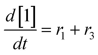
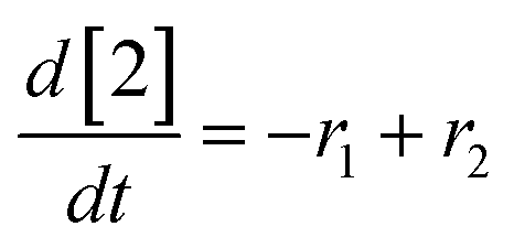
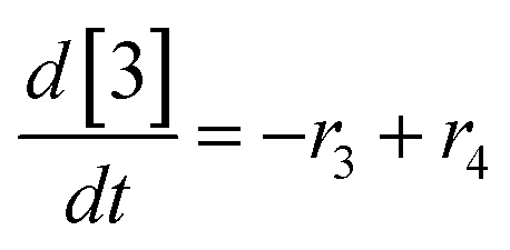
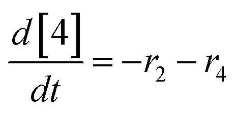
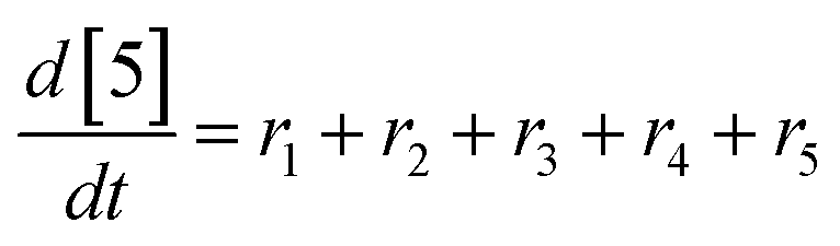
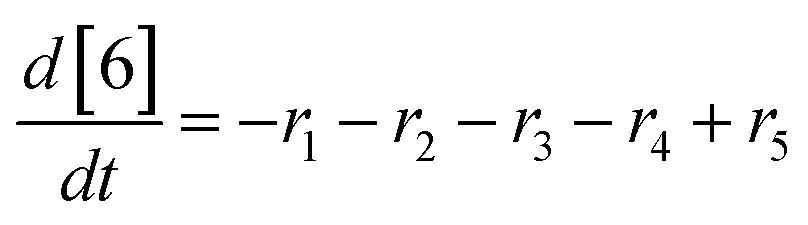
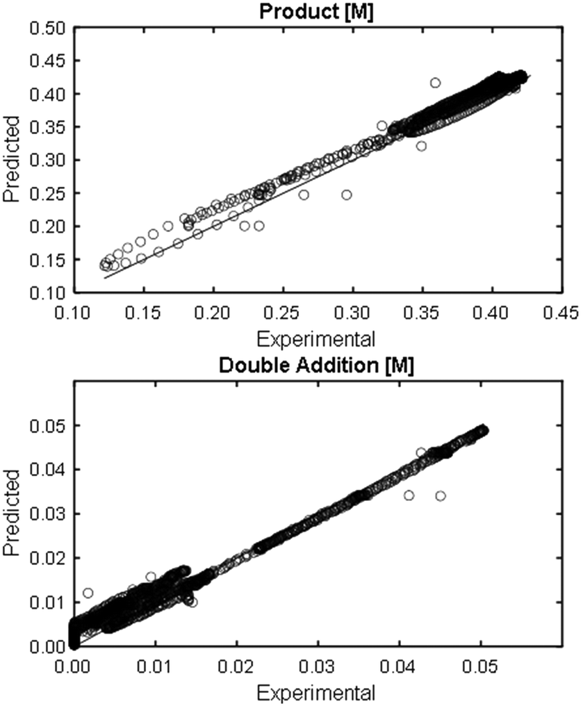
At a cursory glance, results from the automated dynamic optimization provide a set of preferred operating conditions that achieve the desired reaction outcome. Additionally, the dense data set from these investigations can also be used to build a mechanistic model to gain further process insight. This model can be leveraged to better define the design space, establish process robustness, and identify process sensitivities through numerical methods. To demonstrate this potential, the automated dynamic optimization data from this SNAr case study was used to build and regress a precise kinetic model.The set of equations (eqn (11)–(22)) describing the overall reaction network was established from the set of reactions given in Scheme 1. To facilitate kinetic modeling, the equilibrium constant, Keq, for the acid neutralization was estimated from published pKa values for hydrofluoric acid (pKa = 3.8)44 and morpholine (pKa = 8.36).45 The rate constants were regressed by minimizing the weighted sum of squared errors using the quantitative FTIR data and corrected conditions obtained from the dynamic optimization trials. Additional modeling and regression information is provided in the ESI.† The resulting best fit parameters and the associated 95% confidence parameters are listed in Table 2. Parity plots for the desired product (2) and the double addition impurity (4), key species influencing the optimization objective function, are shown in Fig. 11 and highlight the excellent agreement between experimental and predicted reaction performance.
| r1 = −k1[1][5] | (11) |
| r2 = −k2[2][5] | (12) |
| r3 = −k3[1][5] | (13) |
| r4 = −k4[3][5] | (14) |
 | (15) |
 | (16) |
 | (17) |
 | (18) |
 | (19) |
 | (20) |
 | (21) |
 | (22) |
| k 1 (1/M min) | k 2 × 10⁻³ (1/M min) | k 3 × 10⁻² (1/M min) | k 4 × 10⁻² (1/M min) |
|---|---|---|---|
| 0.55 ± 0.7% | 3.84 ± 1.9% | 7.42 ± 0.7% | 3.16± 1.8% |
 | ||
| Fig. 11 Parity plots for product (2) and double addition impurity (4) using proposed kinetic model for predicted values. | ||
This kinetic model was used to profile the product yield, the double addition impurity formation, and the objective function (eqn (5)) over a range of residence times and morpholine equivalents (Fig. 12). These modelled response surfaces illustrate the reaction features that reinforce the experimental results from the automated dynamic optimization. At short residence times and low morpholine equivalents, increasing the morpholine charge leads to the most significant gains in the objective function as more morpholine is needed to counter the neutralization of hydrofluoric acid and increase yield. High yields at minimum residence times can be achieved with super stoichiometric morpholine but similar yields at more modest morpholine levels are realized by extending the residence time. The penalty function, P2, builds this latter preference into the automated dynamic optimization and results in the downward sloping objective values observed at the upper left portion of the design space. In the later searches of the first automated dynamic optimization trial, the algorithm reaches the optimum by balancing residence time and morpholine equivalents while maintaining high yields in the search.
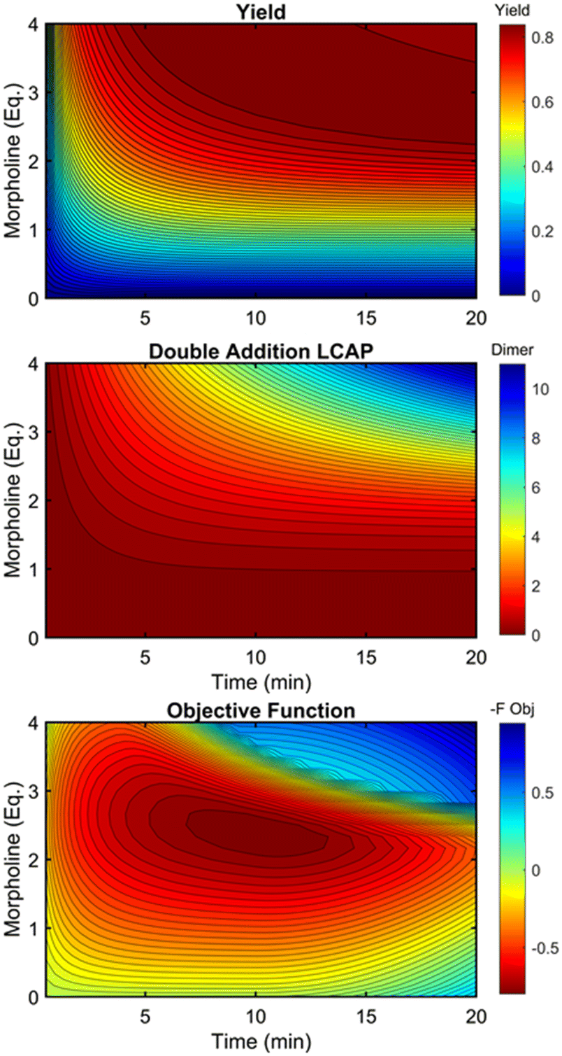 | ||
| Fig. 12 Contour plots of product yield, double addition impurity LCAP, and objective function as functions of residence time and morpholine equivalents using regressed kinetic parameters in Table 2. | ||
At long residence times and high morpholine equivalents, such as those used in investigation #2, the reaction exhibits high yield and elevated double addition impurity levels. These double addition levels, the excessive amounts of morpholine, and the unnecessarily long residence times cause the penalty functions to dominate the objective function value. From this design space area, the automated dynamic optimization searches for conditions that minimize these penalty terms while improving reaction yield. Additionally, as multiple penalty functions are active in this portion of the design space, the objective function improves quickly and significantly along the initial search for the second automated dynamic optimization. In fact, the algorithm quickly approached a region of optimal conditions described by the elliptical plateau of the objective function within the design space of 2.0–2.6 equivalents of morpholine and residence times between 6 and 14 minutes.
Conclusions
As shown in this work, performing autonomous optimization with dynamic flow operations provides a unique, data-rich solution to a common process development problem. The data-dense, multi-dimensional trajectories obtained between the initial and optimal conditions capture the reaction sensitivities over a broad design space, information that would require extensive time and materials under traditional steady state conditions. For drug substance development and manufacturing, this wealth of multi-variate data provides invaluable process knowledge and can be used directly in establishing the operating ranges as process development timelines are further accelerated. Further process understanding is gained by leveraging the automated dynamic optimization datasets to build mechanistic or data-driven process models. As demonstrated, these models can be used to accurately predict trends in reaction product yield and impurity generation. Furthermore, as new process information becomes available, these models can be utilized to update optimal conditions given a new objective function or processing constraints.Growing interest in autonomous optimization in flow chemistry will lead to applications in dynamic optimization for complex reactions and multi-step synthesis. As the size of the optimization problem expands, the knowledge obtained from the data-rich experimentation of dynamic optimization will become increasingly vital for rapid and efficient process development of drug substance compounds. In these situations, alternative algorithms, such as Stable Noisy Optimization by Branch and Fit (SNOBFIT), Bayesian optimization algorithms, multi-objective optimization algorithms, or model-based optimization algorithms, may be more efficient than gradient-based approaches. Adapting these more sophisticated optimization algorithms for dynamic operations to balance efficiency and data-rich experimentation will be of significant value for future research in flow chemistry optimization. Incorporating integer optimization with dynamic flow operations may lead to data-rich routines that simultaneously optimize the selection of reagents and solvents as well as the associated operating conditions. As automated dynamic optimization becomes more prevalent in lab development, it has the potential to extend into manufacturing. At its core, automated dynamic optimization around the target manufacture behaves similarly to several well-established feedback process control strategies. Growing familiarity with feedback control systems in the lab will drive feedback control in production operations, thereby improving the robustness and productivity of these processes in the manufacturing setting.
Author contributions
The authors contributed equally to this work.Conflicts of interest
There are no conflicts to declare.Acknowledgements
We would like to thank Dr. François Lévesque and Dr. Kevin Maloney for insightful discussions around the SNAr chemistry case study and the practical approach of automated flow systems in drug substance development.Notes and references
- J. P. McMullen, C. H. Marton, B. D. Sherry, G. Spencer, J. Kukura and N. S. Eyke, Development and Scale-Up of a Continuous Reaction for Production of an Active Pharmaceutical Ingredient Intermediate, Org. Process Res. Dev., 2018, 22, 1208–1213 CrossRef CAS
.
- N. Salehi Marzijarani, D. R. Snead, J. P. McMullen, F. Lévesque, M. Weisel, R. J. Varsolona, Y.-H. Lam, Z. Liu and J. R. Naber, One-Step Synthesis of 2-Fluoroadenine Using Hydrogen Fluoride Pyridine in a Continuous Flow Operation, Org. Process Res. Dev., 2019, 23, 1522–1528 CrossRef CAS
- D. A. L. Otte, K. Basu, L. Jellett, M. Whittington, G. Spencer, M. Burris, E. B. Corcoran, K. Stone, J. Nappi, R. A. Arvary, D. Donoghue, H. Ren, K. M. Maloney and J. R. Naber, Development of a Green and Sustainable Manufacturing Process for Gefapixant Citrate (MK-7264) Part 4: Formylation–Cyclization as a Flow–Batch Process Leads to Significant Improvements in Process Mass Intensity (PMI) and CO Generated versus the Batch–Batch Process, Org. Process Res. Dev., 2020, 24, 2478–2490 CrossRef CAS
- D. A. Thaisrivongs, J. R. Naber and J. P. McMullen, Using Flow To Outpace Fast Proton Transfer in an Organometallic Reaction for the Manufacture of Verubecestat (MK-8931), Org. Process Res. Dev., 2016, 20, 1997–2004 CrossRef CAS
- C. Bottecchia, F. Lévesque, J. P. McMullen, Y. Ji, M. Reibarkh, F. Peng, L. Tan, G. Spencer, J. Nappi, D. Lehnherr, K. Narsimhan, M. K. Wismer, L. Chen, Y. Lin and S. M. Dalby, Manufacturing Process Development for Belzutifan, Part 2: A Continuous Flow Visible-Light-Induced Benzylic Bromination, Org. Process Res. Dev., 2022, 26, 516–524 CrossRef CAS
- P. Sagmeister, F. F. Ort, C. E. Jusner, D. Hebrault, T. Tampone, F. G. Buono, J. D. Williams and C. O. Kappe, Autonomous Multi-Step and Multi-Objective Optimization Facilitated by Real-Time Process Analytics, Adv. Sci., 2022, 9, 2105547 CrossRef
- C. Mateos, M. J. Nieves-Remacha and J. A. Rincón, Automated platforms for reaction self-optimization in flow, React. Chem. Eng., 2019, 4(9), 1536–1544 RSC
- A. M. Schweidtmann, A. D. Clayton, N. Holmes, E. Bradford, R. A. Bourne and A. A. Lapkin, Machine learning meets continuous flow chemistry: Automated optimization towards the Pareto front of multiple objectives, Chem. Eng. J., 2018, 352, 277–282 CrossRef CAS
- A.-C. Bédard, A. Adamo, K. C. Aroh, M. G. Russell, A. A. Bedermann, J. Torosian, B. Yue, K. F. Jensen and T. F. Jamison, Reconfigurable system for automated optimization of diverse chemical reactions, Science, 2018, 361, 1220–1225 CrossRef
- B. J. Reizman, Y.-M. Wang, S. L. Buchwald and K. F. Jensen, Suzuki–Miyaura cross-coupling optimization enabled by automated feedback, React. Chem. Eng., 2016, 1, 658–666 RSC
- T. von Keutz, J. D. Williams and C. O. Kappe, Flash Chemistry Approach to Organometallic C-Glycosylation for the Synthesis of Remdesivir, Org. Process Res. Dev., 2021, 25, 1015–1021 CrossRef CAS
- N. Uhlig, A. Martins and D. Gao, Selective DIBAL-H Monoreduction of a Diester Using Continuous Flow Chemistry: From Benchtop to Kilo Lab, Org. Process Res. Dev., 2020, 24, 2326–2335 CrossRef CAS
- H. Kim, K. Inoue and J.-i. Yoshida, Harnessing [1,4], [1,5], and [1,6] Anionic Fries-type Rearrangements by Reaction-Time Control in Flow, Angew. Chem., Int. Ed., 2017, 56(27), 7863–7866 CrossRef CAS PubMed
- P. Musci, M. Colella, A. Sivo, G. Romanazzi, R. Luisi and L. Degennaro, Flow Microreactor Technology for Taming Highly Reactive Chloroiodomethyllithium Carbenoid: Direct and Chemoselective Synthesis of α-Chloroaldehydes, Org. Lett., 2020, 22, 3623–3627 CrossRef CAS PubMed
- H. Usutani, Y. Tomida, A. Nagaki, H. Okamoto, T. Nokami and J.-I. Yoshida, Generation and Reactions of o-Bromophenyllithium without Benzyne Formation Using a Microreactor, J. Am. Chem. Soc., 2007, 129, 3046–3047 CrossRef CAS PubMed
- C. J. Taylor, A. Baker, M. R. Chapman, W. R. Reynolds, K. E. Jolley, G. Clemens, G. E. Smith, A. J. Blacker, T. W. Chamberlain, S. D. R. Christie, B. A. Taylor and R. A. Bourne, Flow chemistry for process optimisation using design of experiments, J. Flow Chem., 2021, 11, 75–86 CrossRef CAS
- J. P. McMullen and K. F. Jensen, An Automated Microfluidic System for Online Optimization in Chemical Synthesis, Org. Process Res. Dev., 2010, 14, 1169–1176 CrossRef CAS
- J. P. McMullen, M. T. Stone, S. L. Buchwald and K. F. Jensen, An Integrated Microreactor System for Self-Optimization of a Heck Reaction: From Micro- to Mesoscale Flow Systems, Angew. Chem., Int. Ed., 2010, 49, 7076–7080 CrossRef CAS PubMed
- S. Krishnadasan, R. J. C. Brown, A. J. deMello and J. C. deMello, Intelligent routes to the controlled synthesis of nanoparticles, Lab Chip, 2007, 7, 1434–1441 RSC
- R. A. Bourne, R. A. Skilton, A. J. Parrott, D. J. Irvine and M. Poliakoff, Adaptive Process Optimization for Continuous Methylation of Alcohols in Supercritical Carbon Dioxide, Org. Process Res. Dev., 2011, 15, 932–938 CrossRef CAS
- D. Frey, J. H. Shin, C. Musco and M. A. Modestino, Chemically-informed data-driven optimization (ChIDDO): leveraging physical models and Bayesian learning to accelerate chemical research, React. Chem. Eng., 2022, 7(4), 855–865 RSC
- A. Pomberger, A. A. Pedrina McCarthy, A. Khan, S. Sung, C. J. Taylor, M. J. Gaunt, L. Colwell, D. Walz and A. A. Lapkin, The effect of chemical representation on active machine learning towards closed-loop optimization, React. Chem. Eng., 2022, 7(6), 1368–1379 RSC
- K. E. Konan, A. Abollé, E. Barré, E. C. Aka, V. Coeffard and F.-X. Felpin, Developing flow photo-thiol–ene functionalizations of cinchona alkaloids with an autonomous self-optimizing flow reactor, React. Chem. Eng., 2022, 7(6), 1346–1357 RSC
- K. Y. Nandiwale, T. Hart, A. F. Zahrt, A. M. K. Nambiar, P. T. Mahesh, Y. Mo, M. J. Nieves-Remacha, M. D. Johnson, P. García-Losada, C. Mateos, J. A. Rincón and K. F. Jensen, Continuous stirred-tank reactor cascade platform for self-optimization of reactions involving solids, React. Chem. Eng., 2022, 7, 1315–1327 RSC
- B. J. Reizman and K. F. Jensen, Simultaneous solvent screening and reaction optimization in microliter slugs, Chem. Commun., 2015, 51, 13290–13293 RSC
- H.-W. Hsieh, C. W. Coley, L. M. Baumgartner, K. F. Jensen and R. I. Robinson, Photoredox Iridium–Nickel Dual-Catalyzed Decarboxylative Arylation Cross-Coupling: From Batch to Continuous Flow via Self-Optimizing Segmented Flow Reactor, Org. Process Res. Dev., 2018, 22, 542–550 CrossRef CAS
- L. M. Baumgartner, C. W. Coley, B. J. Reizman, K. W. Gao and K. F. Jensen, Optimum catalyst selection over continuous and discrete process variables with a single droplet microfluidic reaction platform, React. Chem. Eng., 2018, 3, 301–311 RSC
- C. W. Coley, D. A. Thomas, J. A. M. Lummiss, J. N. Jaworski, C. P. Breen, V. Schultz, T. Hart, J. S. Fishman, L. Rogers, H. Gao, R. W. Hicklin, P. P. Plehiers, J. Byington, J. S. Piotti, W. H. Green, A. J. Hart, T. F. Jamison and K. F. Jensen, A robotic platform for flow synthesis of organic compounds informed by AI planning, Science, 2019, 365, eaax1566 CrossRef CAS
- A. D. Clayton, A. M. Schweidtmann, G. Clemens, J. A. Manson, C. J. Taylor, C. G. Niño, T. W. Chamberlain, N. Kapur, A. J. Blacker, A. A. Lapkin and R. A. Bourne, Automated self-optimisation of multi-step reaction and separation processes using machine learning, Chem. Eng. J., 2020, 384, 123340 CrossRef CAS
- A. D. Clayton, A. M. Schweidtmann, G. Clemens, J. A. Manson, C. J. Taylor, C. G. Niño, T. W. Chamberlain, N. Kapur, A. J. Blacker, A. A. Lapkin and R. A. Bourne, Automated self-optimisation of multi-step reaction and separation processes using machine learning, Chem. Eng. J., 2020, 384, 123340 CrossRef CAS
- C. Waldron, A. Pankajakshan, M. Quaglio, E. Cao, F. Galvanin and A. Gavriilidis, Model-based design of transient flow experiments for the identification of kinetic parameters, React. Chem. Eng., 2020, 5, 112–123 RSC
- J. P. McMullen and K. F. Jensen, Rapid Determination of Reaction Kinetics with an Automated Microfluidic System, Org. Process Res. Dev., 2011, 15, 398–407 CrossRef CAS
- J. S. Moore and K. F. Jensen, “Batch” Kinetics in Flow: Online IR Analysis and Continuous Control, Angew. Chem., Int. Ed., 2014, 53, 470–473 CrossRef CAS
- S. Mozharov, A. Nordon, D. Littlejohn, C. Wiles, P. Watts, P. Dallin and J. M. Girkin, Improved Method for Kinetic Studies in Microreactors Using Flow Manipulation and Noninvasive Raman Spectrometry, J. Am. Chem. Soc., 2011, 133, 3601–3608 CrossRef CAS
- S. Schwolow, B. Heikenwalder, L. Abahmane, N. Kockmann and T. Roder, Kinetic and Scale-up Investigations of a Michael Addition in Microreactors, Org. Process Res. Dev., 2014, 18, 1535–1544 CrossRef CAS
- C. A. Hone, N. Holmes, G. R. Akien, R. A. Bourne and F. L. Muller, Rapid multistep kinetic model generation from transient flow data, React. Chem. Eng., 2017, 2, 103–108 RSC
- C. J. Taylor, J. A. Manson, G. Clemens, B. A. Taylor, T. W. Chamberlain and R. A. Bourne, Modern advancements in continuous-flow aided kinetic analysis, React. Chem. Eng., 2022, 7(5), 1037–1046 RSC
- K. C. Aroh and K. F. Jensen, Efficient kinetic experiments in continuous flow microreactors, React. Chem. Eng., 2018, 3, 94–101 RSC
- F. Florit, A. M. K. Nambiar, C. P. Breen, T. F. Jamison and K. F. Jensen, Design of dynamic trajectories for efficient and data-rich exploration of flow reaction design spaces, React. Chem. Eng., 2021, 6, 2306–2314 RSC
- B. M. Wyvratt, J. P. McMullen and S. T. Grosser, Multidimensional dynamic experiments for data-rich process development of reactions in flow, React. Chem. Eng., 2019, 4, 1637–1645 RSC
- A. G. O'Brien, Z. Horváth, F. Lévesque, J. W. Lee, A. Seidel-Morgenstern and P. H. Seeberger, Continuous Synthesis and Purification by Direct Coupling of a Flow Reactor with Simulated Moving-Bed Chromatography, Angew. Chem., Int. Ed., 2012, 51, 7028–7030 CrossRef
- LCAP is an acronym for liquid chromatography area percent. It is measurement commonly used throughout drug substance research and development.
-
K. J. Beers, Numerical Methods for Chemical Engineering Applications in Matlab, Cambridge University Press, New York, 2007 Search PubMed
-
F. A. Carey, Organic Chemistry, McGraw Hill, New York, 4th edn, 2000 Search PubMed
- H. K. Hall, Correlation of the Base Strengths of Amines1, J. Am. Chem. Soc., 1957, 79, 5441–5444 CrossRef CAS
Footnotes |
| † Electronic supplementary information (ESI) available. See DOI: https://doi.org/10.1039/d2re00256f |
| ‡ These authors contributed equally to this work. |
| This journal is © The Royal Society of Chemistry 2023 |