
 Open Access Article
 This Open Access Article is licensed under a Creative Commons Attribution-Non Commercial 3.0 Unported Licence
Enhanced flow synthesis of small molecules by in-line integration of sequential catalysis and benchtop twin-column continuous chromatography†
Alessandra
Sivo
a,
Tae Keun
Kim
 a,
Vincenzo
Ruta
a,
Renzo
Luisi
b,
Jose
Osorio-Tejada
c,
Marc
Escriba-Gelonch
d,
Volker
Hessel
e,
Mattia
Sponchioni
*a and
Gianvito
Vilé
*a
a,
Vincenzo
Ruta
a,
Renzo
Luisi
b,
Jose
Osorio-Tejada
c,
Marc
Escriba-Gelonch
d,
Volker
Hessel
e,
Mattia
Sponchioni
*a and
Gianvito
Vilé
*a
aDepartment of Chemistry, Materials, and Chemical Engineering “Giulio Natta”, Politecnico di Milano, Piazza Leonardo da Vinci 32, IT-20131 Milano, Italy. E-mail: mattia.sponchioni@polimi.it; gianvito.vile@polimi.it
bDepartment of Pharmacy – Drug Sciences, University of Bari “A. Moro”, Via E. Orabona 4, IT-70125 Bari, Italy
cSchool of Engineering, The University of Warwick, CV4 7AL, Coventry, UK
dUniversity of Lleida, Higher Polytechnic Engineering School, Igualada, Spain
eSchool of Chemical Engineering and Advanced Materials, The University of Adelaide, North Terrace Campus, Adelaide, 5005, Australia
First published on 6th September 2022
Abstract
We report an improved approach for the integration of flow synthesis and continuous chromatography, for applications in the end-to-end preparation of pharmaceutically-relevant small molecules. It involves the combination of sequential microreactors and twin-column counter-current chromatography based on the often-used C18 columns. The column loading method ensures that the product breaking through a fully loaded first column is loaded onto the second one, avoiding waste of precious material and technological complexity associated with the use of four-to-six columns typical of simulated moving bed chromatography. The system was applied to synthesize biphenyl via Suzuki–Miyaura reaction, and was also demonstrated for other structurally-different compounds. Compared to the discontinuous and other traditional approaches, our method leads to higher isolated yields (ca. +60%), higher productivity (ca. +30%), and reduced solvent consumption (ca. −80%). A circularity and life-cycle analysis was also conducted to demonstrate the environmental benefits of the flow process.
Introduction
Automatized and smart pharmaceutical processes are necessary to realize iterative design–synthesis–testing platforms (Fig. 1a) that can provide chemical probes and leads for druggable targets.1 Over the past decades, microreactor technology has offered a way to perform chemical reactions with milder, faster, and safer protocols.2 This has been ascribed to the high surface-to-volume ratio of those small-scale reactors, that lead to improved mass and heat transfer.3 The integration of microreactors with in-line process analytical systems and artificial intelligence algorithms has further developed the field, enabling quicker optimization protocols, with several advantages for pharmaceutical and chemical manufacturing.4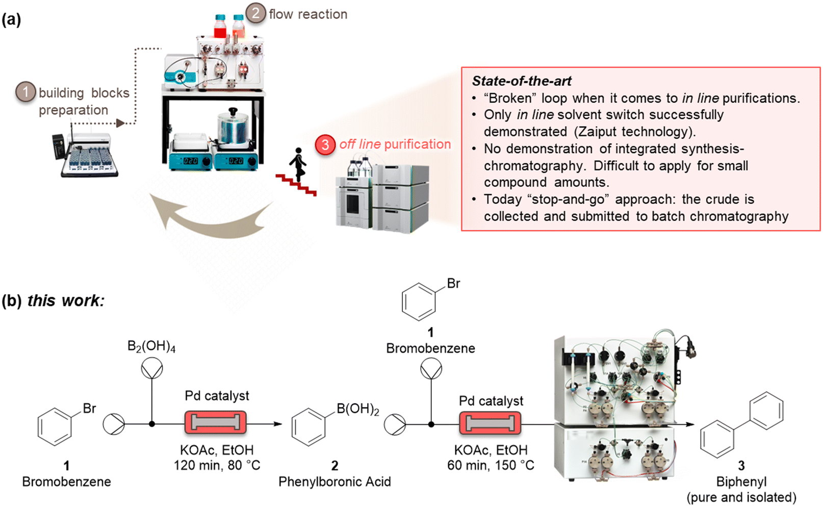 | ||
| Fig. 1 State-of-the-art showing challenges in terms of in-line integration of continuous purification systems with flow platforms (a). Sketch for the integrated and continuous synthesis–purification process reported in this work, for the example of a Suzuki–Miyaura cross coupling reaction (b). | ||
As these benchtop reactors become even more indispensable as a result of their modularity, it is of paramount importance to be able to connect upstream and downstream methods to realize an integrated process. One of the most challenging (and less developed) aspects of microsystem engineering remains the design and in-line integration of benchtop purification processes, which are always needed after a synthetic step (Fig. 1a). Most chemical processes involve multistep reactions, and almost each step needs a downstream purification, that can go from the easy workup to a demanding crystallization and chromatography.5 These downstream steps consume energy, reactants, solvents, and time, with a considerable impact on the environmental footprint and overall efficiency of the process. Despite the high number of downstream unit operations, there are only a few devices which have been suitably designed for integration with microreactors.6 These examples mainly relate to liquid–liquid and liquid–gas extractions used for solvent switch, which are based on Zaiput membranes.7 Technologies such as continuous benchtop crystallizations have not yet provided a method for easy and in-line integration with continuous-flow reactors.8
Significant efforts to integrate in-line purification by column chromatography with continuous-flow synthesis have been undertaken in recent years.9 The first method has been developed by Seeberger and co-workers, by coupling simulated moving-bed (SMB) chromatography with flow synthesis.9a Here, a highly complex system has been used, consisting of a six-column configuration and 48-port valves. The use of multiple dual-mode centrifugal partition chromatography (MDM-CPC) has been also reported.9b This kind of chromatography relies on the use of two non-miscible phases, instead of using a solid stationary phase. Selecting the two phases, or biphasic liquid system (BLS), is elaborate and time-consuming for benchtop application, as it needs to consider various operating parameters, such as the partition coefficients of product in the BLS and the settling time of the phases, which can determine the resolution of the separation. Two studies have been reported based on the use of multiple columns in parallel as a substitute of the countercurrent chromatography for the in-line purification. A supercritical fluid chromatography (SCFC) coupled with a multistep flow synthetic process has been reported by Ley and co-workers.9c Despite the high overall yield of the process, this four-column system of 21 independent items of equipment with additional programming for automatic sampling require many specialists to operate. Vilela and co-workers investigated the use of in-line flash chromatography purification through a two-column configuration with a 10-port valve.9d
All in-line purification technologies mentioned before provided significant advancements to this field, but their system complexity and low injection volumes per cycle (maximum 10 mL) clearly require further improvements. In this work, we propose the capture-SMB technology as a new in-line purification approach, that offers high resolution, yield, and productivity, as well as low solvent consumption. This is achieved by utilizing only two twin columns and a new loading method, in which the product breaking through the outlet of a fully loaded first column is loaded onto the second column, thereby avoiding wasting precious material as well as increasing the process productivity. To integrate synthesis and purification, and build the end-to-end continuous process, a surge tank can be introduced to compensate the different flowrates of the synthesis and purification steps.10 As the mass transfer is improved between the liquid and the resin by the realization of a countercurrent movement between the stationary phase and the mobile phase, a higher resolution, or higher purity, is expected by the application of this technology. Moreover, a built-in software of the capture-SMB technology allows for fully automated operation and the minimum number of multi-port valves minimize the hold-up volume (Fig. 1b).
Experimental section
General information
All reactants were purchased from Sigma-Aldrich and used as such. Product characterization after reaction was done collecting an aliquot of the reaction product and analyzing it by high-performance liquid chromatography (HPLC). This was carried out on an Agilent 1100 series chromatograph equipped with a Thermo Scientific C18 Hypersil GOLD™ column (4.2 mL) and diode array detector (DAD) set at λ = 210 nm. In addition, 1H and 13C nuclear magnetic resonance (NMR) spectra of the products were recorded on a Bruker 400 mHz spectrometer. Batch reactions were performed using 20 mL round-bottom flasks. Flow reactions were conducted on a commercial Uniqsis™ flow microreactor, consisting of an HPLC pump, a T-shaped micromixer, a packed-bed reactor (diameter 1 cm, length 12 cm), a heating module, and a back-pressure regulator of 10 bar.Synthesis of phenylboronic acid (2)
The synthesis of phenylboronic acid was performed either in a batch reactor or under continuous-flow conditions. For the batch experiments, to a stirred solution of bromobenzene 1 (1 mmol, 1 equiv.) in ethanol (5 mL, 0.2 M), dibenzylideneacetone palladium(0) phosphaadamantane ethyl silica (1% mol) and KOAc (3 mmol, 3 equiv.) were added at room temperature. After stirring the mixture for 5 minutes, the heating was set to 80 °C, and the B2(OH)4 (1 mmol, 1 equiv.) was added. The mixture was kept under stirring for another 2 h. After this step, the mixture was cooled down to room temperature, and an aliquot of the reaction mixture was withdrawn for HPLC analysis. For the flow experiments, a solution of bromobenzene 1 (1 mmol, 1 equiv.), B2(OH)4 (1 mmol, 1 equiv.), and KOAc (3 mmol, 3 equiv.) in ethanol (5 mL) was pumped on the commercial Uniqsis™ flow microreactor. The solution passed through a column reactor, packed with dibenzylideneacetone palladium(0) phosphaadamantane ethyl silica (1% mol), kept at fixed temperature. The product outlet was cooled down to room temperature, and an aliquot of the product mixture was withdrawn for HPLC analysis.Synthesis of biphenyl (3)
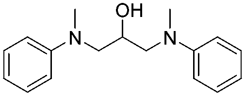
The synthesis of biphenyl was performed either in a batch reactor or under continuous-flow conditions. For the batch experiments, dibenzylideneacetone palladium(0) phosphaadamantane ethyl silica (1% mol) and KOAc (3 mmol, 3 equiv.) were added at room temperature to a solution of bromobenzene 1 (1 mmol, 1 equiv.) in ethanol (5 mL, 0.2 M). After stirring the mixture for 5 minutes, the heating was set to 150 °C, and phenylboronic acid 2 (1 mmol, 1 equiv.) was added to the reaction flask, and stirred for 1 h. After this step, the mixture was cooled down to room temperature, and an aliquot of the reaction mixture was withdrawn for HPLC analysis. For the flow experiments, a solution of bromobenzene 1 (1 mmol, 1 equiv.), phenylboronic acid 2 (1 mmol, 1 equiv.), and KOAc (3 mmol, 3 equiv.) in ethanol (5 mL) were pumped through a commercial Uniqsis™ flow microreactor. The solution passed through a column reactor, packed with dibenzylideneacetone palladium(0) phosphaadamantane ethyl silica (1% mol), kept at fixed temperature. The product outlet was cooled down to room temperature, and an aliquot of the product mixture was withdrawn for HPLC analysis.Synthesis of 1,3-bis[methyl(phenyl)amino]propan-2-ol (4)
A 2.8 M solution of epichlorohydrin (28 mmol, 1 equiv.) in EtOH and a 2.8 M solution of N-methylaniline (28 mmol, 1 equiv.) in EtOH were mixed and pumped through a stainless-steel coil reactor (internal volume = 60 mL) at 80 °C and 60 min. The product outlet was cooled down to room temperature, and an aliquot of the product mixture was withdrawn for HPLC analysis.Synthesis of diphenyl ether (5)
Bromobenzene 1 (0.75 mmol, 1.5 equiv.), CuCl2 (1% mol), and K2CO3 (1 mmol, 2 equiv.) were solubilized in a round-bottom flask using DMF (2 mL) as a solvent. The mixture was heated to 150 °C. At this temperature, phenol (0.5 mmol, 1 equiv.) was added. The mixture was kept under stirring for 24 h. After this step, the mixture was cooled down to room temperature, and an aliquot of the reaction mixture was withdrawn for HPLC analysis.Purifications and capture-SMB technology
The purifications were conducted on a system comprising two long lifetime LED UV detectors (280 and 300 nm recorded simultaneously), and four high-precision double-piston pumps with active seal wash and one fraction collector. The system was equipped with two twin HPLC columns YMC-Triart Prep C18-S20 μm, each with a volume of 1.66 mL. The system was also supported by MControl, a dynamic software which keeps the process at the optimum. Breakthrough curves were collected using a solution composed by 25 mol% of phenylboronic acid and 75 mol% of biphenyl with a concentration of 3.5 mg mL−1. Both batch chromatography and flow multi-column chromatography were performed using the same solution and a linear velocity of 300 cm h−1.The operating conditions of the capture-SMB technology were optimized using the results obtained from the breakthrough (BT) curves. As this twin-column technology uses an interconnected mode, in which the outlet of the upstream column is connected to the inlet of the downstream one, and a batch mode, in which the two columns are disconnected and operate in parallel, timings to switch from the batch to the interconnected mode and vice versa are essential in optimizing the operation of the technology. This process optimization can be easily achieved by inserting the BT points of the product (ranging from 1% to 10% of the product BT), and the desired loading volume (ranging from 65% to 85% of the product BT) obtained from the BT curves. These two experimental points determine the start and the end of the interconnected mode, respectively. After the first step of the process, in which the upstream column undergoes loading and the downstream column undergoes elution, cleaning and equilibration, the two columns are interconnected at the BT point defined for the process, which in this case is equal to 1%. Then, the two columns are disconnected when the desired BT of the upstream column is reached, in this case equal to 70%. The upstream column undergoes the same phases of the downstream column in the first step (i.e., elution, cleaning, and equilibration) while the downstream column continues the loading. In this way, using the twin-column technology efficiently loads the columns to maximize their resin utilization and thus allows for improving its productivity and solvent consumption.
Life cycle assessment
Given that the main reagent utilized (bromobenzene) is derived from fossil resources, the reduction of halobenzene usage would significantly improve the environmental performance of the product life cycle. In this sense, to evaluate the environmental profiles of the analyzed processes, we applied a life cycle assessment (LCA) methodology.11 The LCA focused on the impacts associated with the production of the quantity of bromobenzene utilized per mg of final product. A cradle-to-gate scope and a cut-off system model based on mass allocation was defined. The environmental impact categories of global warming, fine particulate matter formation, and fossil resource scarcity were selected because, among the different 18 categories assessed in the ReCiPe midpoints impacts assessment method,12 the impacts of bromobenzene production on these three categories contribute to over 90% of the aggregated environmental impacts on human health, ecosystems, and resources scarcity. Life cycle inventory for the production of bromobenzene was based on experimental data,12c and the datasets for energy and materials flows based on European market from the life cycle inventory database (Ecoinvent 3.8).12d The heating energy required in the bromobenzene preparation was thermodynamically estimated and adjusted by assuming an efficiency of 60% of the electric heating device.13 The stirring energy was calculated based on a required power of 3.2 W at 700 rpm for stirring a 10 g of mixture and extrapolated to the specific quantity in the bromobenzene experiment. Regarding facilities and transport, a chemicals plant of 50![[thin space (1/6-em)]](https://www.rsc.org/images/entities/char_2009.gif) 000 ton yearly production with a 50 year lifespan and transport by lorry and train for distances of 100 km and 600 km were considered.14 Emissions to air during the process were assumed to be 0.2% of volatile input materials.14b A 90% organic matter removal efficiency was assumed in the wastewater treatment, whose carbon is subsequently released into the air in the form of CO2.14c Finally, the impacts assessment results were obtained using the SimaPro 9.2 software.14d
000 ton yearly production with a 50 year lifespan and transport by lorry and train for distances of 100 km and 600 km were considered.14 Emissions to air during the process were assumed to be 0.2% of volatile input materials.14b A 90% organic matter removal efficiency was assumed in the wastewater treatment, whose carbon is subsequently released into the air in the form of CO2.14c Finally, the impacts assessment results were obtained using the SimaPro 9.2 software.14d
Circularity assessment
Different from the above LCA study, the circularity study investigated the formation of biphenyl, starting from three different halobenzene (chloro, bromo, and iodobenzene). The circularity methodology proposed by the Ellen MacArthur (EMA) foundation was applied, taking the material circular indicator (MCI) with values between 0 (linear) and 1 (circular).15 A production of 100 mg of pure biphenyl was assumed as functional unit. The processes considered were batch and continuous-flow synthesis and included the corresponding batch and continuous purification. To determine the impact of mass recycling, two scenarios were considered: (1) not considering reactant recycling and (2) considering reactant recycling. To this aim, the following hypotheses were taken: (i) all mass flows of the process were calculated according to the functional unit, so the material loads are different between process layouts, but the same between scenarios; (ii) the same reaction yields were taken for the different halogen-based derivatives; (iii) when a reactant was not recycled, it was considered as wasted; (iv) secondary wastes were not considered and, thus, the extraction efficiency (EF) of a recycled reactant was assumed as 100% in all cases; (v) the utility factor F(X), which includes the product intensity and lifetime, was considered invariant in this study. All parameters used were defined according to the definitions and equations given by the Ellen MacArthur (EMA) foundation.15Results and discussion
We initiated the work by optimizing the Suzuki–Miyaura reaction, a classical reaction applied in drug discovery and development, to prepare a biphenyl compound (Fig. 1b). The reaction is made of two steps: a Miyaura borylation where bromobenzene reacts with tetrahydroxydiboron to obtain phenylboronic acid, and a Suzuki C–C cross-coupling where the boronic acid obtained from the previous step reacts with bromobenzene to form biphenyl. The reactions were optimized on the commercial continuous-flow unit described before, equipped with a packed bed filled with Pd-based silica-supported heterogeneous catalyst (dibenzylideneacetone palladium(0) phosphaadamantane ethyl silica). Using a ‘design of experiments’ (DoE) approach, the borylation step was conducted in a systematic manner varying the temperature between 60 and 100 °C, and the residence time between 30 and 120 min. The two reactants were injected together, and the product yield was calculated by HPLC. The full experimental campaign is given in the ESI.† At the optimized 80 °C and 120 min conditions, the compound 2 was obtained with 86% yield (Fig. S1a†). To highlight the advantage of the continuous-flow synthesis, we performed at comparative experimental conditions (i.e., 80 °C and 120 min) the same reaction in a standard round-bottom flask, obtaining compound 2 with only a 67% total yield under batch mode. As discussed elsewhere, the higher yield in flow conditions can be ascribed to the improved contact of the liquid phase with the catalytic sites in flow.16 The second step was performed by using the same continuous set-up described above. The formation of biphenyl was performed by injecting an ethanolic solution of bromobenzene and phenylboronic acid in the packed-bed reactor. Following the DoE approach, the reaction was conducted at different temperatures (from 100 to 150 °C) and residence times (from 30 to 120 min). The maximum yield of compound 3 (58%) was achieved at 150 °C and 60 min (Fig. S1b†). Under batch conditions, compound 3 was achieved with only 45% yield, thus testifying the improvement brought by flow conditions.Having optimized the synthesis, we integrated the two continuous steps together to prepare biphenyl in one pot. We then moved to the development of a suitable purification process. We started from the traditional batch chromatography, in which the crude mixture is discontinuously loaded into a column, packed with a C18 resin, until its capacity is approached. The biphenyl compound obtained from the Suzuki–Miyaura reaction served as model species to demonstrate the effectiveness of this multidisciplinary approach. A breakthrough test was preliminarily carried out on the reaction product in order to determine the dynamic binding capacity of the resin, which is pivotal for establishing the conditions for its optimal utilization (Fig. 2a). The crude, at 2.37 mg mL−1 of product 3, was loaded onto 1.66 mL of C18 resin and the product concentration in the eluate of the column was measured through a calibrated in-line UV-vis detector. The 1% breakthrough (BT), i.e., 1% of the product concentration in the feed, was measured in the eluate after having loaded 34 mL of crude. Considering the operating linear velocity of 300 cm h−1, the saturation time corresponding to the 1% BT was 61.5 min.17 This means that, reached this loading volume, the product starts being lost in the eluate, with no more adsorption on the resin, compromising the yield of the process. This was then considered as the reference loading for a batch single-column chromatography in order to avoid sacrificing the yield of the product. In this condition, a resin loading of 48.5 mg mLresin−1 was achieved. Using this parameter, the initial separations were performed in batch. The crude, with an overall concentration of 3.5 mg mL−1, was loaded up to the 1% BT estimated previously. After the loading, a washing step with 14 mM Na2CO3 was performed to desorb the impurities. Finally, the elution was operated with a step gradient to 100% acetonitrile and 1 mL fractions were collected during this phase to characterize the process. In particular, the yield and the biphenyl concentration in each fraction were determined by at-line HPLC analysis. The overall purity of the biphenyl collected from the batch process was about 86%. The yield, defined as the ratio between collected and injected product, was 51% for the batch process, while the productivity is 17 g h−1 Lresin−1 (Table 1). This poor yield was ascribed to the breakthrough of some product in the loading phase as well as in the washing step, required to desorb the impurities and reach acceptable standards of purity.
 | ||
| Fig. 2 Breakthrough curve for biphenyl product during batch and continuous chromatographic purification (a), showing improved performance over a multi-column continuous setup; photograph of the modified continuous moving bed chromatography setup (b); schematic representation of a half-cycle of the continuous operation, for the loading, washing, elution, and cleaning steps (c); schematic flow diagram of the continuous chromatography setup (d); UV traces of the five performed cycles during continuous synthesis and product purification (e). | ||
| Solvent consumption (L g−1) | Isolated yield (%) | Productivity (g h−1 L−1) | Purity (%) | |
|---|---|---|---|---|
| a Synthesis and purification conditions in Fig. 1b and in the ESI.† b Process improvement between continuous-flow and batch experiments. | ||||
| Batcha | 1.4 | 51.3 | 17.2 | 86.3 |
| Continuous-flowa | 0.3 | 81.3 | 22.7 | >99 |
| Process gainb (batch vs. continuous-flow) | 79.6% | 58.5% | 31.6% | 15.9% |
In order to improve the downstream processing performances, we moved to a continuous countercurrent chromatography process based on two twin columns, directly applying it to our small molecules.12 In this approach, the crude is partialized into multiple columns, which undergo consecutive interconnected (series) and disconnected (parallel) operations ensuring the periodic continuity of the feeding and the necessary steps of cleaning-in-place and regeneration. This leads to higher resin utilization and process efficiency, due to the maximized driving force for mass transfer, ensured by the simulated countercurrent movement between the solid and liquid phases, and therefore an easier scalability for industrial processes. The set-up was composed by two supports for columns, two long lifetime LED UV detectors (280 and 300 nm recorded simultaneously), four high precision double-piston-pumps with active seal wash and one pump for feed supply. The chromatograph was equipped with two HPLC columns YMC-Triart Prep C18-S20 μm, each with a volume of 1.66 mL (Fig. 2b).
The purification cycle involved two phases (Fig. 2c and d): in the first one, the columns are interconnected and are employed in series to ensure that the product breaking through the upstream column during the loading is re-adsorbed in the downstream one. This allowed to push the loading phase to higher values of breakthrough. In this work, 70% BT, corresponding to a loaded volume of 54 mL, was applied. This enabled a higher loading of the resin, up to 77 mg mLresin−1, which in turns grants a better column utilization compared to the single-column configuration. In the second stage, the columns are employed in parallel, performing the washing, elution and regeneration of the upstream column while completing the loading of the downstream one. These two phases constitute a switch, after which the two columns reach the same initial conditions but with exchanged positions (i.e., the upstream column becomes the downstream one and vice versa). Then, a full cycle comprises two symmetrical switches.
In our work, with only five cycles, we were able to purify the compounds. The UV traces recorded at the outlet of one of the two columns for these five cycles are shown in Fig. 2e, confirming the periodicity of the process, with good reproducibility of the chromatogram cycle after cycle. The peak corresponding to biphenyl can be appreciated at 130 min. From in-line HPLC analysis, we demonstrated that this product could be collected with high purity (>99%) in each cycle. The overall process performances of this continuous operation were evaluated by averaging the parameters obtained for the cycles that have reached the steady state (cycles 2, 3, and 4) and are reported in Table 1. In particular, biphenyl can be recovered, through this continuous chromatographic approach, with 81% yield and productivity of 22.7 g h−1 Lresin−1 at a purity of >99%. Thus, the continuous purification process provides increased yield and productivity, respectively by 59% and 32%, compared to the batch process. As shown in Table 1, the batch produced 80.5 mg of the product per run using 57.8 mL of the solvent while the continuous purification was able to produce 127.8 mg of the product per switch using 31.2 mL. This clear advantage could be summarized as the solvent utilized per purified product, or solvent consumption, which was 1.4 L g−1 for the batch and 0.3 L g−1 for the continuous purification. This remarkable reduction in the solvent consumption makes the continuous purification more attractive from an industrial and environmental viewpoint.
The broad applicability of our flow synthesis–purification method was demonstrated testing the protocol on different reaction mixtures. Among this, the symmetric aminoalcohol 4 and the diphenylether 5 were isolated using the same protocols validated above. As reported in Table 2, the separation provided products 4 and 5 in high purity (>90%), and with an overall yield of 68% and 71% respectively. Further information and comparative data with batch methods are in the ESI† (Tables S1 and S2).
| Solvent consumption (L g−1) | Isolated yield (%) | Productivity (g h−1 L−1) | Purity (%) | |
|---|---|---|---|---|
| a Synthesis and purification conditions in the ESI,† Tables S1 and S2. | ||||
 4
4
|
2.4 | 68 | 7.5 | 93 |
 5
5
|
2.4 | 71 | 7.1 | 92 |
The environmental impact as given by the LCA is assumed to be largely dependent on the reactant mass used to achieve the same quantity of product. This paper reported advances in the reduction of reactant mass by flow chemistry, over batch synthesis, and continuous-flow purification, over batch purification. The LCA results show that, indeed, this process intensification is translated into environmental benefits (Fig. 3). As expected, the reduction of the quantity of reagent used per mg of product generates proportionally reductions in the pollutant emissions and fossil resources scarcity. Hence, the total 56.1 mg CO2 eq. emitted due to bromobenzene consumption in the batch synthesis to produce 1 mg of biphenyl are reduced by 51% in the flow synthesis process, i.e., emitting only 27.3 mg CO2 eq. per mg of product. Similarly, air pollutant emissions and the impacts on fossil resources scarcity are halved by switching the production process from batch to flow systems. A similar positive outcome was determined for the environmental impact categories fine particulate matter formation and fossil resource scarcity. Together with the global warming, this provides a forecast both for most urgent global issues (warming, resources) and human health (particulate matter).
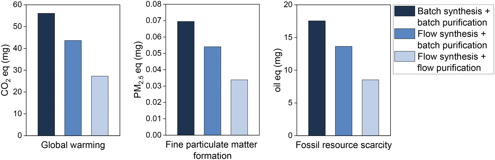 | ||
| Fig. 3 Environmental impacts of bromobenzene used to obtain 1 mg of biphenyl by batch and flow processes. | ||
The circularity assessment goes one step further in scope than the LCA, by considering the route to generate biphenyl. As the focus is on recycling, the lost and recovered mass loads determine the degree of circularity. The mass loads are reduced when switching from batch to continuous-flow, both for the synthesis and purification (Table 3).18 In this sequence, the demand of virgin materials (V) decreases when the process is carried out continuously. Additionally, the recycled fraction (FR) is increased to a maximum value of 0.81, for a continuous synthesis and purification with reactants recycled and assuming synthesis using chlorobenzenes (Table S3†). Waste generation is also positively impacted, reaching a 95% reduction when using chloro-benzenes. The MCI metrics scores largest (0.859) for the best scenario. To summarise, the two-fold continuous process, continuous in synthesis and purification, is considerably better in the environmental performance, as evidenced by the LCA study. The circularity study confirmed this outcome, and outlined that the results would be significantly better when considering recycling of reactant waste and replacing the bromohalogens of the study with chlorohalogens.
| Batch synthesis + batch purification | Flow synthesis + batch purification | Flow synthesis + flow purification | ||||
|---|---|---|---|---|---|---|
| Scenario | A | B | A | B | A | B |
| a M: mass load entering the process. b F R: recycled/recyclable fraction. c V: amount of virgin materials. d C U: reuse fraction. e E F: extraction efficiency. f W: unrecoverable waste. g LFI: linear flow indicator. h F(X): utility factor. i MCI: material circular index. | ||||||
| M (mg)a | 3326 | 3326 | 1661 | 1661 | 1447 | 1447 |
| F R | 0.00 | 0.18 | 0.46 | 0.68 | 0.62 | 0.75 |
| V (mg)c | 3326 | 2733 | 895 | 526 | 550 | 355 |
| C U | 0.00 | 0.18 | 0.46 | 0.68 | 0.62 | 0.75 |
| E F | 1.00 | 1.00 | 1.00 | 1.00 | 1.00 | 1.00 |
| W (mg)f | 3226 | 2633 | 795 | 425 | 450 | 255 |
| LFIg | 0.98 | 0.81 | 0.51 | 0.29 | 0.35 | 0.21 |
| F(X)h | 0.9 | 0.9 | 0.9 | 0.9 | 0.9 | 0.9 |
| MCI | 0.114 | 0.274 | 0.542 | 0.742 | 0.689 | 0.810 |
Conclusions
In conclusion, we have presented an improved protocol for the end-to-end synthesis and multi-column preparative purification of small molecules, in an integrated manner and under continuous conditions. The approach was demonstrated for the synthesis of structurally-different organic compounds. In all cases, the flow method demonstrated higher product yields, quick product isolation, and reduced solvent consumption compared to traditional batch-type chromatography. Circularity and life cycle analyses further highlighted the environmental benefits for the integrated flow process. The approach may find applications in the design of new synthesis–purification–analysis platforms applied in drug discovery.Author contributions
AS, VR, and RL synthesized and characterized the small molecules, optimizing batch and flow protocols. TKK and AS performed the chromatographical purifications in batch and continuous conditions. JO-T, ME-G, and VH performed the circularity and environmental analyses. GV contributed for funding acquisition. GV and MS supervised the research work. AS, TKK, MS, and GV wrote the manuscript with contributions and discussions from all authors. All authors have given approval to the final version of the manuscript.Conflicts of interest
There are no conflicts to declare.Acknowledgements
Funding from the European Commission (GV, grant agreement 101031710), Bracco Imaging (AS, VR, and GV), Fondazione Bracco (GV), and YMC Japan (TKK and MS) is gratefully acknowledged. The authors thank Maria Suanno and Martina Villa for collecting experimental data on Suzuki coupling. Professor Massimo Morbidelli is thanked for useful discussions on continuous manufacturing.Notes and references
- (a) Y. Mo, G. Rughoobur, A. M. K. Nambiar, K. Zhang and K. F. Jensen, Angew. Chem., Int. Ed., 2020, 59, 20890 CrossRef CAS; (b) S. V. Ley, Angew. Chem., Int. Ed., 2018, 57, 5182 CrossRef CAS.
- (a) T. Wan, L. Capaldo, G. Laudadio, A. V. Nyuchev, J. A. Rincón, P. García-Losada, C. Mateos, M. O. Frederick, M. Nuño and T. Noël, Angew. Chem., Int. Ed., 2021, 60, 17893 CrossRef CAS; (b) P. Musci, T. von Keutz, F. Belaj, L. Degennaro, D. Cantillo, C. O. Kappe and R. Luisi, Angew. Chem., Int. Ed., 2021, 60, 6395 CrossRef CAS PubMed.
- (a) K. Lovato, P. S. Fier and K. M. Maloney, Nat. Rev. Chem., 2021, 5, 546 CrossRef CAS; (b) R. C. R. Wootton and A. J. deMello, Nature, 2012, 483, 43 CrossRef CAS PubMed.
- (a) A. M. Schweidtmann, A. D. Clayton, N. Holmes, E. Bradford, R. A. Bourne and A. A. Lapkin, Chem. Eng. J., 2018, 352, 277 CrossRef CAS; (b) S. M. Kearnes, M. R. Maser, M. Wleklinski, A. Kast, A. G. Doyle, S. D. Dreher, J. M. Hawkins, K. F. Jensen and C. W. Coley, J. Am. Chem. Soc., 2021, 143, 18820 CrossRef CAS PubMed; (c) P. Sagmeister, R. Lebl, I. Castillo, J. Rehrl, J. Kruisz, M. Sipek, M. Horn, S. Sacher, D. Cantillo, J. D. Williams and C. O. Kappe, Angew. Chem., Int. Ed., 2021, 60, 8139 CrossRef CAS; (d) I. W. Davies, Nature, 2019, 570, 175 CrossRef CAS PubMed.
- (a) A. Sivo, V. Ruta and G. Vilé, J. Org. Chem., 2021, 86, 14113 CrossRef CAS PubMed; (b) S. Tortoioli, A. Friedli, A. Prud'homme, S. Richard-Bildstein, P. Kohler, S. Abele and G. Vilé, Green Chem., 2020, 22, 3748 RSC.
- (a) A. Adamo, R. L. Beingessner, M. Behnam, J. Chen, T. F. Jamison, K. F. Jensen, J.-C. M. Monbaliu, A. S. Myerson, E. M. Revalor, D. R. Snead, T. Stelzer, N. Weeranoppanant, S. Y. Wong and P. Zhang, Science, 2016, 352, 61 CrossRef CAS PubMed; (b) A. Gioiello, A. Piccinno, A. M. Lozza and B. Cerra, J. Med. Chem., 2020, 63, 6624 CrossRef CAS PubMed.
- (a) J. Imbrogno, L. Rogers, D. A. Thomas and K. F. Jensen, Chem. Commun., 2018, 54, 70 RSC; (b) N. Weeranoppanant and A. Adamo, ACS Med. Chem. Lett., 2020, 11, 9 CrossRef CAS PubMed; (c) I. V. Gürsel, N. Kockmann and V. Hessel, Chem. Eng. Sci., 2017, 169, 3 CrossRef.
- (a) B. J. Doyle, P. Elsner, B. Gutmann, O. Hannaerts, C. Aellig, A. Macchi and D. M. Roberge, Org. Process Res. Dev., 2020, 24, 2169 CrossRef CAS; (b) K. Wen, C. Hu, W. Wu, K. Shvedova, S. C. Born, B. Takizawa and S. Mascia, Org. Process Res. Dev., 2021, 25, 1853 CrossRef CAS.
- (a) A. G. O'Brien, Z. Horváth, F. Lévesque, J. W. Lee, A. Seidel-Morgenstern and P. H. Seeberger, Angew. Chem., Int. Ed., 2012, 51, 7028 CrossRef PubMed; (b) R. Örkényi, J. Éles, F. Faigl, P. Vincze, A. Prechl, Z. Szakács, J. Kóti and I. Greiner, Angew. Chem., Int. Ed., 2017, 56, 8742 CrossRef; (c) D. E. Fitzpatrick, R. J. Mutton and S. V. Ley, React. Chem. Eng., 2018, 3, 799 RSC; (d) C. G. Thomson, C. Banks, M. Allen, G. Barker, C. R. Coxon, A. L. Lee and F. Vilela, J. Org. Chem., 2021, 86, 14079 CrossRef CAS PubMed.
- (a) D. J. Karst, F. Steinebach and M. Morbidelli, Curr. Opin. Biotechnol., 2018, 53, 76 CrossRef CAS PubMed; (b) S. Vogg, T. Müller-Späth and M. Morbidelli, Curr. Opin. Chem. Eng., 2018, 22, 138 CrossRef; (c) V. Warikoo, R. Godawat, K. Brower, S. Jain, D. Cummings, E. Simons, T. Johnson, J. Walther, M. Yu, B. Wright, J. McLarty, K. P. Karey, C. Hwang, W. Zhou, F. Riske and K. Konstantinov, Biotechnol. Bioeng., 2012, 109, 3018 CrossRef CAS PubMed; (d) R. Godawat, K. Konstantinov, M. Rohani and V. Warikoo, J. Biotechnol., 2015, 213, 13 CrossRef CAS PubMed; (e) F. Feidl, S. Vogg, M. Wolf, M. Podobnik, C. Ruggeri, N. Ulmer, R. Wälchli, J. Souquet, H. Broly, A. Butté and M. Morbidelli, Biotechnol. Bioeng., 2020, 117, 1367 CrossRef CAS PubMed.
- Environmental management — Life cycle assessment — Principles and framework, https://www.iso.org/standard/37456.html, 2006 Search PubMed.
- (a) ReCiPe 2016 v1.1 endpoint method, Hierarchist version; (b) M. A. J. Huijbregts, Z. J. N. Steinmann, P. M. F. Elshout, G. Stam, F. Verones, M. D. M. Vieira, A. Hollander, M. Zijp and R. van Zelm, Int. J. Life Cycle Assess., 2017, 22, 138–147 CrossRef; (c) B. S. Furniss, A. J. Hannaford, P. W. G. Smith and A. R. Tatchell, Vogel's textbook of practical organic chemistry, Longman Scientific & Technical, London, 5th edn, 1989, vol. 143 Search PubMed; (d) Ecoinvent LCA database, https://ecoinvent.org/, 2022.
- J. Osorio-Tejada, F. Ferlin, L. Vaccaro and V. Hessel, Green Chem., 2022, 24, 325–337 RSC.
- (a) R. Frischknecht, N. Jungbluth, H.-J. Althaus, G. Doka, R. Dones, S. Hellweg, R. Hischier, T. Nemecek, G. Rebitzer and M. Spielmann, Int. J. Life Cycle Assess., 2005, 10, 112–122 CrossRef; (b) R. Hischier, S. Hellweg, C. Capello and A. Primas, Int. J. Life Cycle Assess., 2005, 10, 59–67 CrossRef CAS; (c) H.-J. Althaus, M. Chudacoff, R. Hischier, N. Jungbluth, M. Osses and A. Primas, Ecoinvent report No. 8, 2007, v2.0 Search PubMed; (d) PRé Consultants, https://pre-sustainability.com/solutions/tools/simapro/, 2022.
- The Ellen MacArthur Foundation Circularity Indicators, https://ellenmacarthurfoundation.org/resources/circulytics/overview (Accessed August 2022).
- (a) A. Simoens, T. Scattolin, T. Cauwenbergh, G. Pisanò, C. S. J. Cazin, C. V. Stevens and S. P. Nolan, Chem. – Eur. J., 2021, 27, 5653 CrossRef CAS PubMed; (b) S. Govaerts, A. Nyuchev and T. Noël, J. Flow Chem., 2020, 10, 13–71 CrossRef CAS; (c) T. Noël and S. L. Buchwald, Chem. Soc. Rev., 2011, 40, 5010–5029 RSC.
- (a) E. Shahbazali, E. M. F. Billaud, A. S. Fard, J. Meuldijk, G. Bormans, T. Noël and V. Hessel, AIChE J., 2020, 67, e17067 Search PubMed; (b) M. Angarita, T. Müller-Späth, D. Baur, R. Lievrouw, G. Lissens and M. Morbidelli, J. Chromatogr. A, 2015, 1389, 85 CrossRef CAS PubMed; (c) T. K. Kim, C. Botti, J. Angelo, X. Xu, S. Ghose, Z. J. Li, M. Morbidelli and M. Sponchioni, Ind. Eng. Chem. Res., 2021, 60, 10764 CrossRef CAS.
- M. Escribà-Gelonch, G. A. de Leon Izeppi, D. Kirschneck and V. Hessel, ACS Sustainable Chem. Eng., 2019, 7, 17237–17251 CrossRef PubMed.
Footnote |
| † Electronic supplementary information (ESI) available. See DOI: https://doi.org/10.1039/d2re00242f |
| This journal is © The Royal Society of Chemistry 2022 |