Sulphur poisoning, water vapour and nitrogen dilution effects on copper-based catalyst dynamics, stability and deactivation during CO2 reduction reactions to methanol†
Received
5th November 2021
, Accepted 4th January 2022
First published on 5th January 2022
Abstract
To reduce CO2 emissions, a flexible process operation for chemical methanol synthesis may be required as the supply of renewable energy-based feedstocks fluctuates. Analysis for the determination of the changing conditions of the long-term activity of catalysts is therefore important for efficient industrial production. A commercial Cu/ZnO/Al2O3 catalyst and five other materials (CuBaTiOX, CuCaTiOX, CuCeAlOX, CuSrAlOX and CuSrTiOX), prepared using solution combustion methods, were tested at two different pressures (p), followed by ageing at high temperature (T) jumps to show the effects of sensitivity. Surfaces were characterized by N2 physisorption, scanning electron microscopy, coupled with energy dispersive spectroscopy (SEM-EDS), and crystallographic X-ray diffraction (XRD) with additional structural Rietveld refinement. Stability reduction mechanisms were assessed, a model was developed with the applied relative partial p of reaction product species as input, and, for CuCeAlOX, it was demonstrated that the kinetics of deactivation is related to a unified H2O gage p distribution, while excluding the correlations of other four prevalent gases (hydrogen, carbon dioxide, carbon monoxide and methanol). An activity decrease can be predicted. Interestingly, synthesized SrCO3-containing mixtures exhibited a lesser loss of initial methanol synthesis activity at 50 bar than at 20 bar during time-on-stream increased T application. In addition, the activity relationship of the catalysts with N2 and H2S poisoning was described. A linear performance differentiation as a function of the amount of H2S impurity was observed, presented and mechanistically modelled. Carbon capture and utilisation technologies, power-to-liquid and e-fuels, will often require (realistic) non-steady state dynamics, which we herein simulate catalytically.
1 Introduction
Partial reduction of CO2 emissions in the industry sectors can be achieved by the production of H2 using H2O electrolysis while avoiding the use of fossil carbon sources for example for ammonia and hydrogen peroxide production. In the case of cement production, CO2 produced purely from CaCO3 calcination (without CO2 emissions caused by a heating source) is responsible for 2.5% of overall emissions and cannot be simply avoided.1 CO2 sequestration in underground wells is a viable solution; however, a concentrated CO2 source could also be used for chemical production.2 Methanol synthesis from CO2 instead of the synthesis from syn-gas is now a validated industrial process.3
There are additional problems associated with the use of CO2 from industrial sources. CO2 hydrogenation to MeOH or CO also produces H2O, which can affect catalyst activity and stability.4 In addition, industrial CO2-rich streams may also contain impurities (e.g., H2S and N2). Another important aspect is that flexible process operation of methanol synthesis may be required due to fluctuations in the supply of renewable energy feedstocks.5,6 Therefore, there is a need for modelling of catalyst activity and various influences on long-term operation. As far as we know, catalyst deactivation models can predict the activity change under constant conditions7–9 and as a function of temperature,10 while the dependence on pressure or gas composition is not considered in the model for methanol synthesis.
Sehested et al.11 have constructed and validated a model for nickel nanoparticle growth that takes into account the influence of temperature and gas composition, specifically the ratio of H2O to H2. In our previous study,12 we aged CuZnAl catalysts at different gas compositions and found a significant effect of H2O partial pressure on the growth of Cu nanoparticles due to the loss of the Al2O3 support.
In this study, we prepared several catalysts (CuSrTi, CuBaTi, CuCaTi, CuSrAl, and CuCeAl) using a solution combustion method based on the optimum conditions and compositions in our previous study.13 Long-term deactivation tests were performed on the prepared and commercial CuZnAl catalysts at two different pressures with the addition of temperature jumps to show the effects of these two conditions on catalyst stability. Based on the work of Sehested et al.11 and our previous work, a model of activity change was developed that could be used to predict deactivation at different temperatures and pressures. In addition, the effect of H2S was determined to show its effects on activity over the long term. A nitrogen-containing input feedstock was assessed in order to examine if this could be fed to the reactor without any harmful effects to the catalysts (e.g. the formation of surface nitrogen species) or by decreasing the selectivity on the account of the production of unwanted side products. Indeed, this largely confirmed that nitrogen acts as a diluting agent, which can be of interest economically, if the costs of compression can be minimised (the application of the surplus electrical energy to compressor as well), as the latter predominantly increase upon N2 use. Conversely, upon such an operating scenario, the costs of an upstream CO2 capture unit may be significantly reduced, as the required input purity of the feedstock can be decreased dramatically, reducing the burden on either amine absorption columns or pressure swing adsorption.
2 Experimental
2.1. Catalyst synthesis
The catalysts were synthesized by a solution combustion method14 and are based on the synthesis optimization in our previous work.13 Here, we prepared CuSrTi, CuBaTi, CuCaTi, CuCeAl and CuSrAl samples in a molar ratio of cations 5![[thin space (1/6-em)]](https://www.rsc.org/images/entities/char_2009.gif) :3:2. Appropriate quantities of Sr(NO3)2, Ba(NO3)2, Ca(NO3)2, Cu(NO3)2, Ce(NO3)3, Al(NO3)3 or titanium tetraisopropoxyde were weighted in a 250 mL alumina crucible in the stoichiometric ratio of cations (above) to produce 10 g of the powder after calcination. Citric acid was also added as a fuel and a complexing agent in a molar ratio of citric acid to cations equals to 1.5.15,16 After the addition of 10 mL of H2O and mixing, a gel is formed. The crucible is covered with a stainless-steel mesh and inserted in the furnace at 650 °C for 12 h without gas purging. The catalysts were then pelletized by compressing in a hydraulic press and then crushed and sieved (250–400 μm). Cu/ZnO/Al2O3 (CuZnAl) is a commercial catalyst (HiFuel W230, Alfa Aesar). State-of-the-art industrial Cu/ZnO/Al2O3 catalysts are typically prepared by a coprecipitation method.17
:3:2. Appropriate quantities of Sr(NO3)2, Ba(NO3)2, Ca(NO3)2, Cu(NO3)2, Ce(NO3)3, Al(NO3)3 or titanium tetraisopropoxyde were weighted in a 250 mL alumina crucible in the stoichiometric ratio of cations (above) to produce 10 g of the powder after calcination. Citric acid was also added as a fuel and a complexing agent in a molar ratio of citric acid to cations equals to 1.5.15,16 After the addition of 10 mL of H2O and mixing, a gel is formed. The crucible is covered with a stainless-steel mesh and inserted in the furnace at 650 °C for 12 h without gas purging. The catalysts were then pelletized by compressing in a hydraulic press and then crushed and sieved (250–400 μm). Cu/ZnO/Al2O3 (CuZnAl) is a commercial catalyst (HiFuel W230, Alfa Aesar). State-of-the-art industrial Cu/ZnO/Al2O3 catalysts are typically prepared by a coprecipitation method.17
2.2. Catalyst characterization
Energy dispersive spectroscopy was performed on a scanning electron microscope (SEM) SUPRA35 VP (Carl Zeiss) coupled with an EDS detector Inca 400 (Oxford Instuments). The presence of a carbon signal by carbon tape in the EDS analysis was avoided by using powder samples filling in the 3 mm wide holes of Al holders. The analyses were performed at three locations for every sample, at 20 kV and using a 120 μm aperture size for 1 min. BET specific surface areas were determined by N2 physisorption. Measurements were performed on a Micromeritics ASAP 2020, with degassing at 200 °C for 17 h with 100 mg of the sample. A PANalytical X'Pert Pro instrument with a CuKα1 radiation source was used for XRD analyses. The measurements were performed between 10° to 90°. All samples except CuZnAl and CuSrAl were analysed after calcination. Those two were reduced in H2 under the same conditions as for the catalytic tests and then transferred and analysed in an Ar atmosphere (CuZnAl) or in air (CuSrAl). Rietveld refinement (RR) was performed to determine the phase content in the samples.
2.3. Catalyst deactivation studies
2.3.1. Long-term stability studies with temperature jumps.
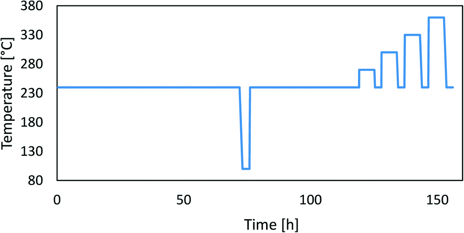
To assess the catalyst deactivation, we performed long-term operation experiments at two different pressures (20 bar and 50 bar) over 5 days followed by accelerated ageing experiments at higher temperatures. The pelletized (and sieved) catalysts (1 mL) were inserted in the parallel packed bed reactor and reduced in a pure H2 flow at 300 °C and 1 bar for 12 h. Bed densities can be found in Table 3. After reduction, the catalysts were aged at 240 °C in a H2/CO2/N2 mixture with a gas composition of 69/23/8 at a gas hourly space velocity (GHSV) of 6000 h−1 at 20 bar for 5 days. Later, we performed accelerated ageing with 6 hour-long high-temperature jumps (at 270 °C, 300 °C, 330 °C and 360 °C). After each temperature rise, we cooled the catalyst back to the starting condition (240 °C) and measured the catalytic activity. During the parallel operation, we lowered the temperature in the reactor to 100 °C for a short amount of time, at which point the catalytic reactions stopped. This was a simple test to check the operation of the catalyst testing system. After this, we repeated the procedure with a fresh catalyst at 50 bar. Kurtz et al.18 previously performed a similar stability test with high-temperature jumps. The temperature cycle is shown in Fig. 1.
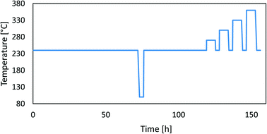 |
| | Fig. 1 A typical temperature profile during the experiment. | |
2.3.2. Activity tests with H2S added in the gas stream.
H2S deactivation tests were performed on the three catalysts; CuSrTi, CuCaTi and CuZnAl catalysts. The tests were run at 240 °C, 20 bar, GHSV 40000 1/h, and at the ratio H2/CO2 = 3 with the addition of 8.1 ppm H2S in the gas feed. H2S was added with a mass flow controller as a 0.5% mixture of H2S in N2. Reduction of the catalysts was performed at 300 °C for 12 h and firstly tested for several hours without H2S addition to obtain the initial activity. After that, a gas mixture of 0.5% H2S was added to obtain 8.1 ppm H2S in the inlet gas feed for 30 h. A description and the result of N2 effect assessment can be found in the ESI,† section 4.
2.4. Modelling of catalyst deactivation
2.4.1. Effect of reaction constituents.
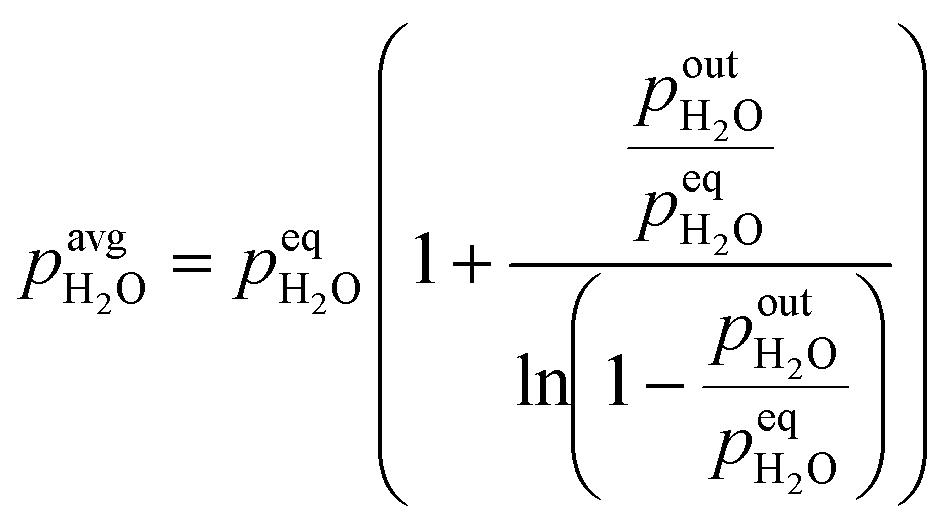
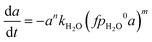
Firstly, we focus on the determination of the effect of reaction constituents on deactivation. This involves the presentation of the model equation and the determination of the average ageing partial pressure. Eqn (1) describes the effects of parameters on the rate of catalyst deactivation.| | 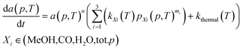 | (1) |
Generally, the sintering-induced deactivation rate decreases with time, since bigger particles are generally more stable. Therefore, term an is added to include the effect of the past catalyst deactivation. The n factor can range between 1 and 16.9 A summation factor represents the effect of gas composition (partial pressure of MeOH, CO, and H2O), multiplied by the corresponding deactivation constant. kthermal represents the deactivation that could be attributed to thermal sintering in the reducing environment (H2/CO2 mixture) and is independent of reaction pressure. All parameters k are temperature-dependent and follow the Arrhenius relation (eqn (2)).| |  | (2) |
The parameters k are obtained through optimization to the changes in the activities after each temperature step and exposure to the partial pressure of each compound. It has to be noted that parameters n and mi can be partially temperature-dependent. Fichtl et al.8 for example obtained an optimization value of n = 3 at 220 °C and n = 4 at 250 °C and 280 °C for CuZnAl.
Calculation of the average partial pressure affecting the catalyst is not trivial. Based on the calculations of the Peclet number in the ESI,† section 1, the advection transport prevails (minimal Pe = 75). This means that there is only a small amount of mixing of the gas phase along the catalyst bed and a plug flow reactor model (PFR) could be used to describe the system. For this reason, we approximate the change of partial pressure along the axial direction using a model of reversible first-order reaction in the PFR. Below (eqn (3)) is an example of an average H2O partial pressure calculation.
| | 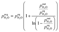 | (3) |
At low outlet
pout, the average
p converges to one half of the outlet partial pressure, since there is a linear increase of partial pressure along the bed length starting from 0 to the outlet partial pressure. At high outlet
p, the average
p converges to equilibrium partial pressure. The dependency of the average partial pressure on the outlet partial pressure can be found in the ESI,
† section 2, wherein estimation errors are also shown. Due to the uncertainty of the equilibrium partial pressure determination, we selected the top boundary of the above equation to be equal to 95% of the equilibrium pressure, while for the values above 95%, an average partial pressure has been set to the equilibrium partial pressure. Equilibrium partial pressures were determined using GASEQ software.
19 Determination of the average partial pressure would be much more straightforward in the case of performed experiments at low Peclet number (high axial dispersion), since we could directly use the measured concentration at the outlet as the average ageing concentration. Overall, the parameter optimization was due to changing temperatures and ageing pressures performed using numerical integration in Excel using a generalized reduced gradient algorithm. Additionally, we performed a validation of this approach by integrating the activity part of the equation, while the time derivative was integrated numerically. Equations are presented in the ESI,
† section 2. The objective function is a sum of squared differences between the model (
amod) and experimental activity (
aexp). The objective function (OF) is weighted to represent the optimization of isothermal ageing and temperature jumps equally:
| | 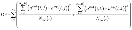 | (4) |
In
eqn (4),
Np represents the number of experiments at different pressures, and
Nvar represents the number of measurements during temperature variation ageing (after the increase of the temperature to 270 °C) while
Niso represents the number of measurements during isothermal ageing at 240 °C.
4
2.4.2. Effect of H2S.
H2S-induced deactivation differs from reaction product-induced deactivation. Generally, H2S strongly first binds to the outer part of the catalyst pellet20 and therefore causes faster deactivation of large particles (industrial pellet: 3–5 mm) than of small particles. The effectiveness factor (ratio of the average rate of the reaction in the particle to the rate on the surface of the particle) is below 1 (ref. 21) and can range from 0.4 to 1 for 4.2 mm particles.22 In our previous work,23 we did not observe any activity change by varying the particle size between 0.1 mm and 0.55 mm. Therefore, deactivation in H2S was described using a simple linear (0th order) model based on the active site deactivation by surface sulphide formation. The relationship between the normalized catalyst activity and parameters related to catalyst poisoning can be found in eqn (5). The equation also includes ∅inlet, which is the volumetric gas inlet flow under standard conditions, mcat is a catalyst mass, CH2S is a concentration of H2S in the inlet gas feed, t is time and kintrinsic is the intrinsic coefficient of the catalyst deactivation rate related to the catalyst structure and composition.| | 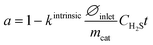 | (5) |
3 Results and discussion
3.1. Catalyst characterization
The rate and the mechanism of catalyst deactivation can depend on the catalyst composition and structure. Compiled findings from SEM-EDS, XRD and N2 physisorption analyses are presented here. The catalyst composition determined using SEM-EDS is shown in Table 1. Besides the cations and oxygen, we observed a large presence of carbon due to the formation of carbonates in the samples containing Sr, Ba or Ca. The cation ratios of the CuSrTi, CuBaTi and CuCaTi samples are very similar to the nominal cation ratio, while the ratio of CuSrAl and CuCeAl deviates significantly. Both include a larger fraction of aluminium than intended, which could be due to the over estimation of the hydration number of Al(NO3)3·9H2O (dehydrated Al(NO3)3 containing 76% more Al than the nominal one per unit of mass). The CuZnAl includes also 24 wt% (47 at%) of carbon, which is used as a binder.
Table 1 The composition of the samples was determined using EDS
| Elements (CuXY) |
Nom. comp. Cu–X–Y [at%] |
Composition [at%] |
EDS comp. Cu–X–Y [at%] |
| Cu |
X |
Y |
O |
C |
| CuSrTi |
50–30–20 |
17.4 |
9.3 |
6.1 |
54.8 |
12.5 |
53–28–19 |
| CuBaTi |
50–30–20 |
14 |
9.1 |
6.2 |
56.5 |
14.2 |
48–31–21 |
| CuCaTi |
50–30–20 |
19.2 |
8.3 |
7.8 |
53.2 |
11.6 |
54–24–22 |
| CuSrAl |
50–30–20 |
6.4 |
2.1 |
5.1 |
73.5 |
12.9 |
47–16–37 |
| CuCeAl |
50–30–20 |
6.1 |
1.8 |
5.6 |
80.4 |
6.1 |
45–13–42 |
| CuZnAl |
45–34–21 |
11.5 |
6.6 |
4.6 |
29.9 |
47.4 |
51–29–20 |
The XRD diffractograms were simulated using Rietveld refinement to determine the phase compositions (ESI,† section 3). Cu is in all samples in the form of CuO before reduction. CuSrTi, CuBaTi and CuCaTi contain corresponding perovskite titanates (SrTiO3, BaTiO3, and CaTiO3) and carbonates (SrCO3, BaCO3, and CaCO3), while a small fraction of TiO2 is also present. The titanate to carbonate ratio could be increased by calcination at a higher temperature. At 800 °C, the content of SrTiO3 increases from 10.7% to 34.5%.13 CuSrTi also contains a layered perovskite structure (Sr2TiO4) and a fraction of residual strontium nitrate. Aluminium was observed only in the form of a Sr2Al2O4 phase and a small amount in α-Al2O3 in the case of CuSrAl, while these forms were not observed in the CuCeAl sample. Most of Al is therefore in the form of an amorphous-like form. Similarly to CuSrTi, CuSrAl also contains a large fraction of SrCO3, while CuSrAl contains a lower amount of residual strontium nitrate. CuCeAl exhibits only CuO and CeO2 phases. It is expected that CuO and CeO2 are being reduced in the form of Cu and CeOX under reaction conditions.24 The XRD analyses of CuZnAl and CuSrAl were performed after the H2 reduction, which does not affect the findings of structure–activity change relations. CuZnAl did not contain CuO, since it was analysed in Ar, while CuSrAl was analysed in air (Table 2).
Table 2 Rietveld refinement of the XRD diffractograms of the investigated samples
| CuSrTi |
CuBaTi |
CuCaTi |
CuSrAl |
CuCeAl |
CuZnAl |
| Phase |
w [%] |
Phase |
w [%] |
Phase |
w [%] |
Phase |
w [%] |
Phase |
w [%] |
Phase |
w [%] |
| CuO |
43.3 |
CuO |
42.1 |
CuO |
59.0 |
CuO |
42.9 |
CuO |
40.2 |
Cu |
78.9 |
| SrTiO3 |
10.7 |
BaTiO3 |
11.6 |
CaTiO3 |
27.9 |
SrAl2O4 |
8.7 |
CeO2 |
59.5 |
ZnO |
21.1 |
| SrCO3 |
35.7 |
BaCO3 |
37.5 |
CaCO3 |
13.0 |
SrCO3 |
42.8 |
|
|
|
|
| TiO2 |
4.1 |
TiO2 |
8.8 |
TiO2 |
0.1 |
Al2O3 |
1 |
|
|
|
|
| Sr2TiO4 |
4.3 |
|
|
|
|
Sr(NO3)2 |
0.3 |
|
|
|
|
| Sr(NO3)2 |
1.8 |
|
|
|
|
Cu |
4.3 |
|
|
|
|
Table 3 contains specific surface areas (SSA), specific pore volumes (Vpore) and average pore size (dpore) determined using N2 physisorption. The surface area increases in the following order CuBaTi < CuSrTi < CuCaTi, while Ti replacement with Al does not have a large impact on CuSrTi on the specific surface area. The highest surface area belongs to the CuCeAl and CuCaTi samples (23 and 22 m2 g−1, respectively). Again, the N2 physisorption analysis of CuZnAl is performed after the H2 reduction. The surface area of the synthesized catalyst is low compared to that of the commercial reference (CuZnAl); however, the aim of the study is to understand the effect of the reaction atmosphere on various prominent materials. The surface area of CuZnAl (52 m2 g−1) is comparable to those in the literature data (40–68 m2 g−1).25
Table 3 Specific surface area (BET), specific pore volume, and average pore size determined using N2 physisorption and the pelletized catalyst bed density
| Name |
SSA (m2 g−1) |
V
pore [cm3 g−1] |
d
pore [nm] |
Bed density [g mL−1] |
| CuSrTi |
15 |
0.01 |
26 |
1.45 |
| CuBaTi |
5 |
0.02 |
16 |
0.94 |
| CuCaTi |
22 |
0.14 |
26 |
0.76 |
| CuSrAl |
12 |
0.04 |
12 |
1.18 |
| CuCeAl |
23 |
0.1 |
21 |
1.52 |
| CuZnAl |
52 |
0.21 |
16 |
1.20 |
3.2. Long-term stability test and modelling
Fig. 2 shows the methanol synthesis activity change over time at 20 bar and 50 bar for all samples. In most cases, the activity decreases gradually at a constant temperature, followed by a sharp activity decreasing due to high-temperature aging steps. Surprisingly, the activity increases at 240 °C in the case of CuCaTi at 20 bar after 120 hours on stream, which could be due to some phase transformation or due to uncovering of the active copper surface. An increase of specific activity was observed by long-term H2O-promoted Al2O3 phase removal from the copper surface in the case of the CuZnAl catalyst.26 During the operation at 50 bar, the mass flow controller of the H2/CO2/N2 mixture temporarily malfunctioned (for 20 h) resulting in an increased H2/CO2 ratio during that period. Apparently, this caused an increase in the CuSrTi activity, while the activity of the other samples remained unaffected. The activity typically decreases faster at 50 bar. Interestingly, the activity of the CuSrAl catalyst decreased slower at 50 bar (−5%) than that at 20 bar (−15%) after high-temperature jumps. Similar results were observed for CuSrTi, where the activity decreased by 20% after high temperature jumps at 20 bar and only 13% at 50 bar. Both contain SrCO3 which could cause such behaviour. By comparing the CuSrTi and CuSrAl catalysts, both lost 10% of the activity after 120 h at 240 °C and 20 bar, while after ageing at 360 °C, the CuSrAl and CuSrTi catalysts retained 75% and 71% of the activity, respectively, showing the slightly higher stability of CuSrAl. The activity drop was the most pronounced in the case of the CuCeAl catalyst which was lost after 120 h at 240 °C 30% of the activity at 20 bar and 45% of the activity at 50 bar. By contrast to the Sr, Ba and Ca compounds, the Ce4+ ions in CeO2 can be easily reduced to Ce2O3 (ref. 24) which could be the reason for the accelerated deactivation. The commercial catalyst CuZnAl showed 14% deactivation at 50 bar after 120 h at 240 °C, while the results at 20 bar are invalid due to measured conversion near to thermodynamic equilibrium conversion at 240 °C. In other words, a smaller catalyst mass or higher flow rate should be used to detect catalyst deactivation. Still, however, we do not observe a drastic activity decrease during the ageing process at 20 bar. The maximum proximity to the equilibrium of the CuZnAl test at 50 bar and 240 °C was 61% for CuZnAl, while for the rest, the highest proximity was equal to 37% at 20 bar and 240 °C and 25% at 50 bar and 240 °C.
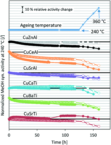 |
| | Fig. 2 Normalized methanol synthesis activity at 240 °C during stability tests. The empty markers (○) represent the data at 20 bar and full markers (●) represent the data at 50 bar. The activity points after high-temperature jumps were aligned to the same times to increase clarity. The activity data of the CuZnAl test at 20 bar are shown in light-colour due to proximity to the equilibrium at 240 °C. | |
Table 4 shows the initial absolute MeOH synthesis productivity and initial MeOH synthesis selectivity. Based on the 50 bar tests, the most active catalyst is CuZnAl, followed by CuCeAl, CuSrTi, CuCaTi, CuSrAl and then CuBaTi. The data for CuZnAl are shown in grey-colour due to thermodynamic equilibrium proximity. The productivities were calculated using eqn (S11) (ESI†), while the MeOH synthesis selectivity was calculated based on the outlet molar fractions of MeOH and CO, since there were no other carbon-based compounds.
Table 4 Overall initial MeOH synthesis productivity and MeOH synthesis selectivity at 20 and 50 bar. GHSV: 6000 1/h; 240 °C. The data for the CuZnAl test at 20 bar are shown in light-colour due to proximity to the equilibrium at 240 °C
| Name |
20 bar |
50 bar |
| Init. MeOH prod. (gMeOH h−1 Lcat.−1) |
Init. MeOH selectivity (%) |
Init. MeOH prod. (gMeOH h−1 Lcat.−1) |
Init. MeOH selectivity (%) |
| CuSrTi |
62.5 |
38.9 |
106.5 |
58.4 |
| CuBaTi |
42.3 |
49.9 |
71.0 |
58.4 |
| CuCeAl |
64.9 |
37.3 |
117.7 |
53.6 |
| CuSrAl |
40.5 |
33.1 |
75.4 |
46.2 |
| CuCaTi |
51.9 |
38.9 |
101.1 |
50.7 |
| CuZnAl |
155.9 |
39.6 |
338.7 |
70.2 |
To elucidate the effect of the operating pressure on the catalyst activity, we developed a model based on eqn (1), which takes into account isothermal ageing as well as high-temperature jumps. The most pronounced deactivation was for the CuCeAl catalyst and for this reason, we selected it for modelling. Additionally, an additional increase of the activity as for the CuCaTi or CuSrTi samples or a change in deactivation trends as for CuSrTi and CuSrAl was not observed which would require further investigation of the catalyst. In addition, both CuCeAl and commercial CuZnAl commonly have Al. Al2O3 in CuZnAl primarily acts as a stabilizing agent, which separates Cu and ZnO nanoparticles to avoid particle coarsening.12 Crucial in CuZnAl deactivation during CO2 hydrogenation is the presence of H2O, which was linked to the Cu nanoparticle growth. For this reason, we calculated the average ageing pressures (CO, MeOH, H2O and total pressure) using eqn (3).
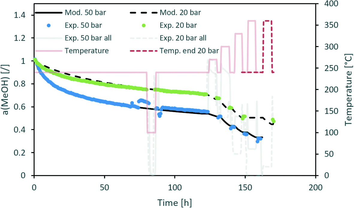
Fig. 3 contains a comparison of the measured and modelled activity using H2O partial pressure as a deactivation parameter. The effect of steam is temperature-dependent with an apparent activation energy of 20 kJ mol−1. In addition, H2O partial pressure is raised to the power of 1.3. All parameters can be found in Table 5. Uncertainty of each parameter was determined based on the 100% increase of the maximum difference between the modelled and experimentally measured activity. From the results, we can see that among all optimized parameters, the apparent activation energy is the least variable.
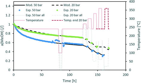 |
| | Fig. 3 Modelling of the CuCeAl deactivation catalyst using the average H2O vapour pressure to account for the effect of pressure. | |
Table 5 The optimized parameters of the temperature-dependent deactivation model
| Catalyst |
CuCeAl |
CuZnAl |
|
n [/] |
4.3 ± 0.9 |
10 ± 4 |
|
m (H2O) [/] |
1.3 ± 0.3 |
1.3 ± 0.7 |
|
A (H2O) [bar−m h−1] |
5.3 ± 2.5 |
840 ± 700 (470–1500) |
|
E
a (H2O) [kJ mol−1] |
20 ± 2 |
56 ± 2.6 |
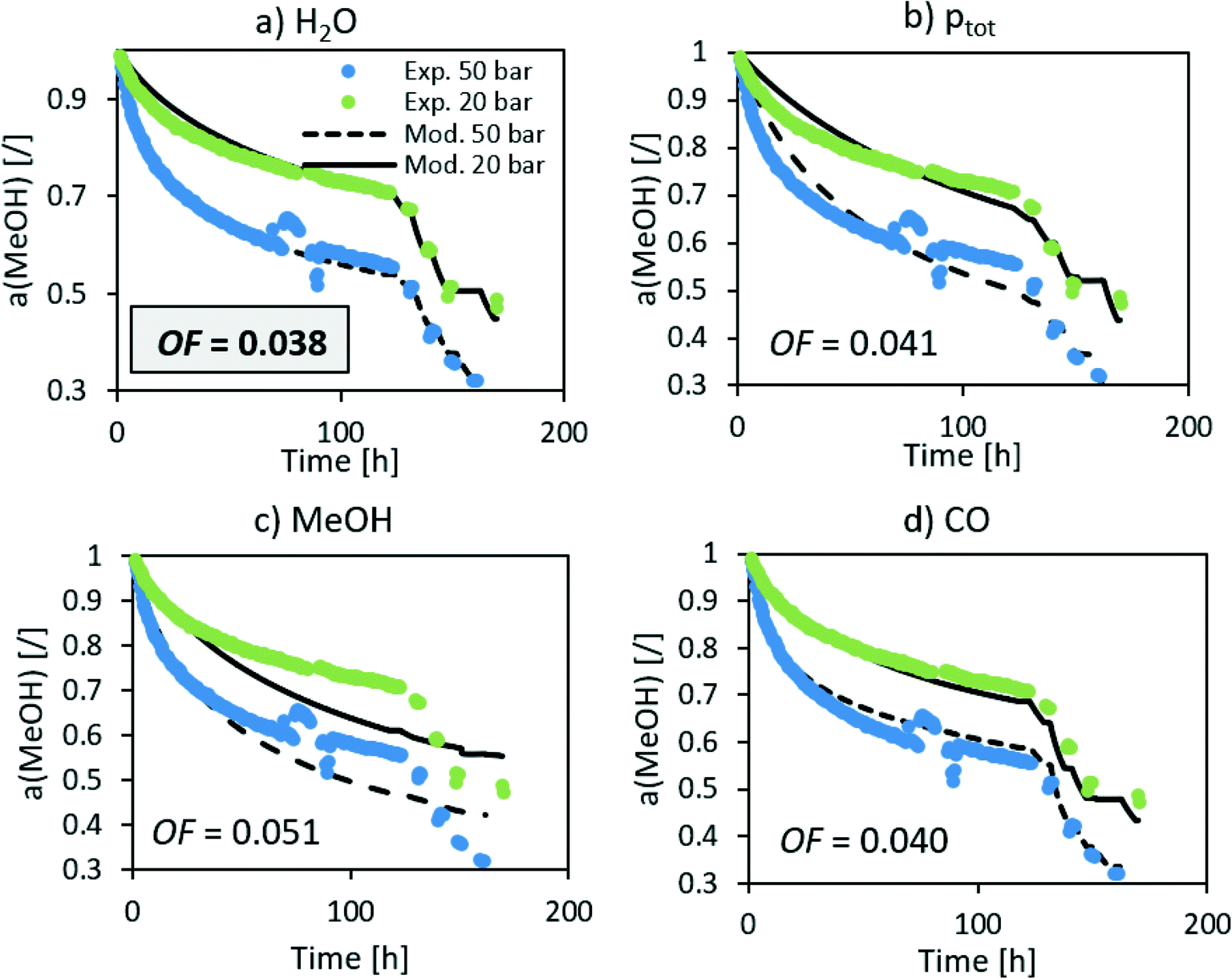
The n in the an factor in eqn (1) is mainly dependent on the isothermal activity change while the determination of m in the factor pm in the same equation is dependent on the change of the activity at different operating pressures. Although the model equation is slightly different, a similar m factor (1.0 ± 0.2) was obtained by Sehested et al.11 for the growth of Ni particles in various H2O/H2 atmospheres. During the optimization procedure, we also included the factor of the pressure in dependent deactivation contribution (kthermal); however, the optimal value Athermal converged to 0. This means that the deactivation mechanism is gas composition dependent. The model sufficiently describes the activity change using H2O partial pressure. At high temperatures, H2O and CO molar productions are due to the low MeOH synthesis rate being nearly the same. In other words, due to the same trends of CO and H2O concentrations, it is impossible to distinguish between the effects of CO and H2O at high temperature. To confirm that the main cause of deactivation is indeed steam-related, we also performed an optimization using the average ageing partial pressure of CO and MeOH. Additionally, we performed a baseline simulation using the total pressure as the ageing pressure. Fig. 4 shows a comparison of the experimental data with the model results with different ageing pressures as an input. The methanol synthesis is low at high temperatures, and therefore the model with MeOH partial pressure cannot describe the activity change, especially at those temperatures. The model with the total pressure as the ageing temperature overestimates an activity decrease at 50 bar at the isothermal part of the test to compensate for the lower activity change at high-temperature jumps. The use of carbon monoxide partial pressure increases the prediction of the activity change. To show the biggest difference between CO and H2O, we need to focus on the low-temperature part of the experiment where there is a higher MeOH selectivity (therefore low CO selectivity). The value of an objective function during isothermal ageing is 73% higher in the case of CO than that for H2O, while a similar deviation is observed in the modelling of high-temperature jumps. In addition, by performing optical revision shown in Fig. 4, we can observe that the model with p(H2O) yields the best description of the experiment.
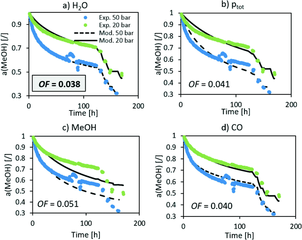 |
| | Fig. 4 Optimization of the deactivation of CuCeAl by selecting different ageing pressures (a) H2O, b) total pressure, c) MeOH and d) CO). | |
We also modelled a 50 bar experiment test of the commercial CuZnAl catalyst using p(H2O) and the same value of the factor m as for the CuCeAl catalyst (Fig. 5). We can see a good comparison between the experiment and model. However, the n factor needed to be changed from 4.3 (CuCeAl) to 10 (CuZnAl) which is a large change. In addition, the apparent activation energy increased from 20 kJ mol−1 (CuCeAl) to 56 kJ mol−1 (CuZnAl) showing that the activity decreases much faster with the temperature increase in the case of CuZnAl. It is known that particle coarsening is not the only reason for the CuZnAl deactivation. At high CO + MeOH partial pressure, ZnOX overgrows the Cu nanoparticles, resulting in a decreased active surface area.12,23,27 In addition, changing the gas composition results in different coverage levels of active ZnOX fragments over a copper surface.23,28,29 Therefore, here we avoid the mechanistic descriptions of the optimized parameters due to complex behaviour.
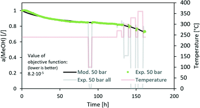 |
| | Fig. 5 Modelling of the deactivation of the CuZnAl catalyst using the average H2O vapour pressure. | |
Eqn (1) is here numerically solved due to changing temperature and H2O ageing partial pressure. For isothermal operation, the differential part could be integrated to explicitly calculate a. Water is a reaction product and its quantity depends on the activity. If we assume that the selectivity for MeOH synthesis does not change during deactivation, we could rewrite eqn (1) to use the change of activity instead of the change of H2O partial pressure (eqn (5)).
| |  | (6) |
where
pH2O0 represents the outlet H
2O partial pressure at
t = 0 and
f represents the factor of the average partial pressure (
pavg/
pout). If the entire catalyst is exposed to the outlet partial pressure (CSTR),
f = 1, while if conversion is far from equilibrium and partial pressure increases along the catalyst bed,
f = 0.5. For the packed bed reactor under the conditions between those two extremes, one could use
eqn (3) to estimate
f. After integration and rearrangement, we obtained a temporal activity change (
eqn (6)).
| | 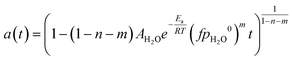 | (7) |
The above equation could be therefore used to simulate deactivation at any given temperature and pressure in the boundaries of conditions where model parameters were defined, as long as the initial partial pressure of H
2O is known. This could be obtained with kinetic models or experimental results.
3.3. Catalytic tests with H2S addition
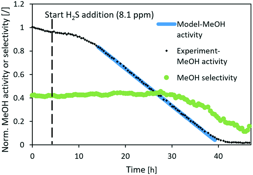
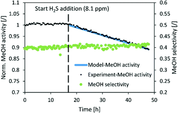
Fig. 6–8 show the normalized activity (a) and methanol selectivity for the three catalysts in the dependence of time. In all cases, the activity drops linearly with time (or added H2S) which is in line with the equation since there are no intraparticle mass transfer limitations. For CuSrTi, methanol synthesis activity drops from 100% to 5% in 17 h at 8.1 ppm H2S and a GHSV of 40000 1/h (Fig. 6). The initial MeOH productivities can be found in Table 6.
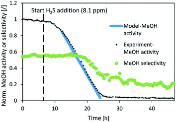 |
| | Fig. 6 Normalized MeOH synthesis activity and selectivity of the CuSrTi catalyst for the test run with 8.1 ppm H2S. Operating conditions: 240 °C, 20 bar, H2/CO2 = 3, GHSV (40000 1/h). | |
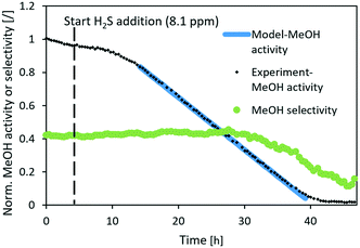 |
| | Fig. 7 Normalized MeOH synthesis activity and selectivity of the CuCaTi catalyst for the test run with 8.1 ppm H2S. Operating conditions: 240 °C, 20 bar, H2/CO2 = 3, GHSV (40000 1/h). | |
 |
| | Fig. 8 Normalized MeOH synthesis activity and selectivity of the commercial CuZnAl catalyst for the test run with 8.1 ppm H2S. Operating conditions: 240 °C, 20 bar, H2/CO2 = 3, GHSV (40000 1/h). | |
Table 6 Parameters, MeOH productivity and deactivation coefficients for the three different catalysts
| Sample |
m [g] |
φ(tot) [NmL min−1] |
H2S conc. [ppm] |
φ(H2S) [μmol min−1] |
k(intrinsic) [g mL−1] |
Init. MeOH prod. (gMeOH h−1 Lcat.−1) |
| CuSrTi |
0.150 |
74.9 |
8.1 |
0.027 |
0.285 |
130 |
| CuCaTi |
0.106 |
67.3 |
8.1 |
0.024 |
0.103 |
165 |
| CuZnAl |
0.12 |
71.4 |
8.1 |
0.026 |
0.012 |
345 |
Interestingly, the methanol selectivity started to decrease (in favour of CO) in the 18 h of the experiment when the normalized activity decreases below 55%. It is suggested that the active site for the hydrogenation reaction on the copper surface represents crystal step edges,30 while H2 can be activated on low index crystal planes such as Cu(111)31 and H atoms can then diffuse to the hydrogenation active site.32 Adsorption of H2S on low index planes could reduce activation of H2, and therefore limit the rate of hydrogenation. The hydrogen reaction order for CO formation is between −0.13 and 0.3 while for MeOH formation, it is between 0.87 and 1.02 over Cu/SiO2.33 This indicates higher dependence of hydrogen availability on MeOH than that on the CO synthesis rate. The reason that the selectivity drops after the activity drops below 55% (delay of selectivity response) could be due to sufficient H2 activation on the available metal copper surface and relatively fast surface H diffusion. The activation energy of H diffusion to the neighbouring site on Cu(111) is 11 kJ mol−1,32 while the activation energy of relevant hydrogenation reactions could reach 150 kJ mol−1 on the more active Cu(533).34 Therefore, surface diffusion of H is to some extent faster than the reactions that consume H.
Similarly, the normalized activity of CuCaTi dropped linearly (Fig. 7), however, at a smaller rate. In addition, MeOH selectivity similarly started to decrease after the activity dropped below 40%. The slower rate of CuCaTi deactivation could be due to the higher specific surface area of the catalyst (22 m2 g−1) compared to 15 m2 g−1 of the CuSrTi catalyst. H2S binds to the Cu surface, while it can also be adsorbed on the TiO2 surface.35,36 There is no TiO2 phase observed in CuCaTi, while it is possible that TiO2-terminated CaTiO3 could still adsorb H2S.
The normalized activity of the commercial CuZnAl catalyst also decreased linearly in the presence of H2S, however, with a much slower rate than those in the case of CuSrTi and CuCaTi. The activity dropped by 10% after 30 h of exposure to 8.1 ppm H2S at 40000 GHSV (Fig. 8). CuZnAl has a higher specific surface area than the other two (52 m2 g−1), while ZnO also adsorbs H2S.37 No change of selectivity was observed, most likely because of a low activity decrease.
The apparent deactivation coefficients were obtained by regression from the experimental results and the intrinsic deactivation coefficients were calculated using eqn (4). In Table 6, we can observe the intrinsic coefficients for deactivation by H2S. The coefficient for CuSrTi is equal to 0.285 g mL−1, for CuCaTi is 0.103 g mL−1 and for CuZnAl is equal to 0.012 g mL−1. Since the coverage of the H2S absorbing compounds varies among the samples, the intrinsic coefficients cannot be simply correlated with the specific surface area.
A model is useful for the prediction of deactivation rates with H2S under arbitrary conditions. Here, we use eqn (4) to show the normalized activity under conditions that are much more similar to the industrial process with the maximal nominal concentration of H2S in the gas treated with dry H2S adsorber unit (GHSV: 2000 1/h; cH2S = 0.1 ppm) for one year of operation (Fig. 9). The model does not include the particle size effect on the activity decrease prediction. We can observe that the normalized activity drops by 16% and 34% for CuCaTi and CuSrTi, respectively, while the activity of CuZnAl drops less (1.8%) after one year of operation.
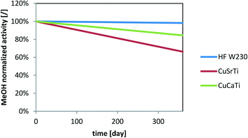 |
| | Fig. 9 Simulation of MeOH activity deactivation due to the H2S impact at a GHSV of 2000 1/h and 0.1 ppm H2S. | |
3.4. Effect of N2 on the activity
The analysis, with the variation of N2 in the gas mixture (0%, 10%, 20% and 30%) (ESI,† section 4), shows that N2 primarily acts as a diluting agent. Removal of N2 from the feed gas for methanol synthesis is crucial, since in the industrial process, the N2 concentration can increase in the recycle loop. To mitigate this, a higher purge flow from the recycle loop is needed with the increasing N2 content in the inlet gas.
4 Conclusions
The change from CO-rich to a CO2-rich feedstock for methanol synthesis influences the overall activity and stability. The produced water at the CO2 hydrogenation increases the rate of deactivation. The results of long-term activity tests on CuSrTi, CuBaTi, CuCaTi, CuSrAl, CuCeAl and CuZnAl at two different pressures (20 bar and 50 bar) at 240 °C show the effect of pressure on catalyst deactivation. Additionally, ageing at high-temperature jumps results in accelerated deactivation. The presence of SrCO3 apparently causes the lower rate of deactivation at 50 bar than at 20 bar at high-temperature jumps, showing complex behaviour. The Al-containing catalysts (CuCeAl and CuZnAl) were subjected to modelling with the ageing pressure of reaction products and operating temperature as an input, showing that the deactivation can be best linked with water vapour pressure. The developed model can be used at various pressures and temperatures allowing a flexible deactivation prediction.
In addition, H2S-induced deactivation tests were performed. Sulphur compounds are typically present in the CO2-rich streams of various industrial sources such as steel and cement production. The copper-based catalysts are vulnerable to H2S catalyst poisoning and for this reason, we performed catalytic tests with H2S addition. We observed a linear activity decrease with the amount of added H2S for all three tested catalysts (CuSrTi, CuCaTi and CuZnAl) and developed a model, which could be translated to industrial applications. N2 was found to reduce the overall methanol synthesis productivity by diluting the gas mixture and decrease the partial pressure of active compounds.
Author contributions
Anže Prašnikar: conceptualization, methodology, validation, formal analysis, investigation, resources, data curation, writing – original draft, and visualization. Blaž Likozar: conceptualization, writing – review & editing, supervision, and funding acquisition.
Conflicts of interest
There are no conflicts to declare.
Acknowledgements
This research was supported by the Slovenian Research Agency (research core funding no. P2-0152) and the Project FReSMe (no. 727504). The authors acknowledge Matic Grom, Neja Strah Štefančič and Alen Plajnšek for the help with reactor operation, Urška Kavčič for N2 physisortion analyses, Janvit Teržan for the special SEM-EDS holder and Edi Kranjc for XRD measurements. A. P. is very grateful to Eric van Dijk from TNO for the fruitful discussion on H2S deactivation.
References
- E. Worrell, L. Price, N. Martin, C. Hendriks and L. O. Meida, Annu. Rev. Energy, 2001, 26, 303–329 CrossRef.
- G. A. Olah, Angew. Chem., Int. Ed., 2005, 44, 2636–2639 CrossRef CAS PubMed.
- W. Wang, S. Wang, X. Ma and J. Gong, Chem. Soc. Rev., 2011, 40, 3703–3727 RSC.
- J. Wu, M. Saito, M. Takeuchi and T. Watanabe, Appl. Catal., A, 2001, 218, 235–240 CrossRef CAS.
- C. Seidel, A. Jörke, B. Vollbrecht, A. Seidel-Morgenstern and A. Kienle, Chem. Eng. Sci., 2018, 175, 130–138 CrossRef CAS.
- K. F. Kalz, R. Kraehnert, M. Dvoyashkin, R. Dittmeyer, R. Gläser, U. Krewer, K. Reuter and J. D. Grunwaldt, ChemCatChem, 2017, 9, 17–29 CrossRef CAS PubMed.
-
I. Løvik, Doctoral thesis, Norwegian University of Science of Technology, 2001 Search PubMed.
- M. B. Fichtl, D. Schlereth, N. Jacobsen, I. Kasatkin, J. Schumann, M. Behrens, R. Schlögl and O. Hinrichsen, Appl. Catal., A, 2015, 502, 262–270 CrossRef CAS.
-
J. Skrzypek, J. Sloczyński, J. Słoczyński and S. Ledakowicz, Methanol synthesis: science and engineering, Polish Scientific Publishers, 1994 Search PubMed.
- C. Seidel, A. Jörke, B. Vollbrecht, A. Seidel-Morgenstern and A. Kienle, Comput.-Aided Chem. Eng., 2018, 43, 85–90 CAS.
- J. Sehested, J. A. P. Gelten and S. Helveg, Appl. Catal., A, 2006, 309, 237–246 CrossRef CAS.
- A. Prašnikar, A. Pavlišič, F. Ruiz-Zepeda, J. Kovač and B. Likozar, Ind. Eng. Chem. Res., 2019, 58, 13021–13029 CrossRef.
-
A. Prašnikar, V. D. B. C. Dasireddy and B. Likozar, Submitt., 2021.
- V. D. B. C. Dasireddy and B. Likozar, Renewable Energy, 2019, 140, 452–460 CrossRef CAS.
- S. R. Jain, K. C. Adiga and V. R. P. Verneker, Combust. Flame, 1981, 40, 71–79 CrossRef CAS.
- G. Saito, Y. Nakasugi, N. Sakaguchi, C. Zhu and T. Akiyama, J. Alloys Compd., 2015, 652, 496–502 CrossRef CAS.
- M. Behrens, Catal. Today, 2015, 246, 46–54 CrossRef CAS.
- M. Kurtz, H. Wilmer, T. Genger, O. Hinrichsen and M. Muhler, Catal. Lett., 2003, 86, 77–80 CrossRef CAS.
-
C. Morley, Gaseq v. 0.79, http//Error! Hyperlink reference not valid, (accessed 1.5.2019).
- Y. Weiyong, F. Dingye and Z. Bingchen, Fuel Sci. Technol. Int., 1995, 13, 289–302 CrossRef.
- N. Park, M. J. Park, Y. J. Lee, K. S. Ha and K. W. Jun, Fuel Process. Technol., 2014, 125, 139–147 CrossRef CAS.
- G. H. Graaf, H. Scholtens, E. J. Stamhuis and A. A. C. M. Beenackers, Chem. Eng. Sci., 1990, 45, 773–783 CrossRef CAS.
- A. Prašnikar, D. L. Jurković and B. Likozar, Appl. Catal., B, 2021, 292, 120190 CrossRef.
- S. D. Senanayake, P. J. Ramirez, I. Waluyo, S. Kundu, K. Mudiyanselage, Z. Liu, Z. Liu, S. Axnanda, D. J. Stacchiola, J. Evans and J. A. Rodriguez, J. Phys. Chem. C, 2016, 120, 1778–1784 CrossRef CAS.
- T. Lunkenbein, F. Girgsdies, T. Kandemir, N. Thomas, M. Behrens, R. Schlögl and E. Frei, Angew. Chem., Int. Ed., 2016, 55, 12708–12712 CrossRef CAS PubMed.
-
A. Prašnikar, D. L. Jurković, B. Likozar, D. Lašič Jurković and B. Likozar, Submitted, 2021, 292, 120190.
- T. Lunkenbein, F. Girgsdies, T. Kandemir, N. Thomas, M. Behrens, R. Schlögl and E. Frei, Angew. Chem., Int. Ed., 2016, 55, 12708–12712 CrossRef CAS PubMed.
- S. Kuld, M. Thorhauge, H. Falsig, C. F. Elkjær, S. Helveg, I. Chorkendorff and J. Sehested, Science, 2016, 352, 2920 CrossRef PubMed.
- S. Kuld, C. Conradsen, P. G. Moses, I. Chorkendorff and J. Sehested, Angew. Chem., Int. Ed., 2014, 53, 5941–5945 CrossRef CAS PubMed.
- R. van den Berg, G. Prieto, G. Korpershoek, L. I. van der Wal, A. J. van Bunningen, S. Lægsgaard-Jørgensen, P. E. de Jongh and K. P. de Jong, Nat. Commun., 2016, 7, 13057 CrossRef CAS PubMed.
- K. Cao, G. Fu, A. W. Kleyn and L. B. F. Juurlink, Phys. Chem. Chem. Phys., 2018, 1, 22477–22488 RSC.
- D. Kopač, B. Likozar and M. Huš, ACS Catal., 2020, 10, 4092–4102 CrossRef PubMed.
- A. Karelovic, G. Galdames, J. C. Medina, C. Yévenes, Y. Barra and R. Jiménez, J. Catal., 2019, 369, 415–426 CrossRef CAS.
- D. Kopač, B. Likozar and M. Huš, Appl. Surf. Sci., 2019, 497, 1–9 CrossRef.
- A. Junkaew, P. Maitarad, R. Arróyave, N. Kungwan, D. Zhang, L. Shi and S. Namuangruk, Catal. Sci. Technol., 2017, 7, 356–365 RSC.
- S. H. Orojlou, B. Zargar and S. Rastegarzadeh, J. Nat. Gas Sci. Eng., 2018, 59, 363–373 CrossRef CAS.
- M. V. Twigg and M. S. Spencer, Appl. Catal., A, 2001, 212, 161–174 CrossRef CAS.
Footnote |
| † Electronic supplementary information (ESI) available. See DOI: 10.1039/d1re00486g |
|
| This journal is © The Royal Society of Chemistry 2022 |
Click here to see how this site uses Cookies. View our privacy policy here. 
 Open Access Article
 This Open Access Article is licensed under a Creative Commons Attribution-Non Commercial 3.0 Unported Licence
 *
*