 Open Access Article
Rational construction of ZnO/CuS heterostructures-modified PVDF nanofiber photocatalysts with enhanced photocatalytic activity†
Chuanfeng Zanga,
Hao Chena,
Xiangye Hana,
Wei Zhang*a,
Junfang Wua,
Fanghua Lianga,
Jiamu Daia,
Hongchao Liub,
Guangyu Zhang *a,
Ke-Qin Zhang
 c and
Mingzheng Ge
 *abc
*abc
aSchool of Textile and Clothing, Nantong University, Nantong 226019, P. R. China. E-mail: zhangwei@ntu.edu.cn; zgyu85@ntu.edu.cn; mingzhengge@umac.mo
bInstitute of Applied Physics and Materials Engineering, University of Macau, Macau 999078, P. R. China
cJiangsu Engineering Research Center of Textile Dyeing and Printing for Energy Conservation, Discharge Reduction and Cleaner Production, National Engineering Laboratory for Modern Silk, College of Textile and Clothing Engineering, Soochow University, Suzhou 215123, P. R. China
First published on 29th November 2022
Abstract
PVDF/ZnO/CuS photocatalysts with ZnO/CuS heterojunctions were synthesized via electrospinning, hydrothermal, and ion-exchange techniques. As matrix materials, electrospun PVDF nanofibers are easy to be recycled and reused. ZnO nanorods anchored on PVDF nanofiber with high specific surface area provide abundant active reaction sites for photocatalysis. While the loaded CuS nanoparticles as a photosensitizer compensate the low quantum efficiency of ZnO and improve the visible-light photocatalytic efficiency. As a result, the PVDF/ZnO/CuS composited photocatalyst exhibits outstanding photocatalytic performance in exposure to UV and visible light owing to the suppressed recombination of electron–hole pairs and widened visible light absorption range. The kinetic constants of PVDF/ZnO/CuS nanocomposites under UV irradiation (9.01 × 10⁻³ min−1) and visible light (6.53 × 10⁻³ min−1) irradiation were 3.66 and 2.53 times higher than that of PVDF/ZnO (2.46 × 10⁻³ min−1 & 2.58 × 10⁻³ min−1), respectively. Furthermore, PVDF/ZnO/CuS nanocomposites demonstrate excellent robustness in terms of recycling and reuse, which is advantageous in practical applications.
1. Introduction
Human production activities such as industry, agriculture, and transportation have made environmental pollution problems increasingly prominent. A large number of emissions of waste gas, heavy metal wastewater, and dyes have wholly exceeded the carrying capacity and self-healing ability of the environment.1 According to previously published reports, more than 11% (about 700![[thin space (1/6-em)]](https://www.rsc.org/images/entities/char_2009.gif) 000 tons) of dyes are discharged into industrial wastewater each year worldwide.2 The release of these complex organic dyes into the environment has resulted in significant pollution and harm to human health. As a result, it is critical to address the environmental pollution problem. Thus, semiconductor photocatalysts have received much attention to overcome these issues. For example, photocatalysts, such as ZnO and TiO2, are frequently utilized for organic dye removal.3–5 TiO2 and ZnO are claimed to have comparable wide band gap (∼3.3 eV), but the better photocatalytic degradation efficiency of low-cost ZnO for a variety of organic dyes in acidic and alkaline environments has piqued the interest of a large number of researchers.6–9 However, the low quantum efficiency of ZnO as a result of the quick photogenerated electron/hole recombination drastically lowers photocatalytic performance. Meanwhile, the extremely limited range of its spectral response results in a low visible-light photocatalytic activity.10–15
000 tons) of dyes are discharged into industrial wastewater each year worldwide.2 The release of these complex organic dyes into the environment has resulted in significant pollution and harm to human health. As a result, it is critical to address the environmental pollution problem. Thus, semiconductor photocatalysts have received much attention to overcome these issues. For example, photocatalysts, such as ZnO and TiO2, are frequently utilized for organic dye removal.3–5 TiO2 and ZnO are claimed to have comparable wide band gap (∼3.3 eV), but the better photocatalytic degradation efficiency of low-cost ZnO for a variety of organic dyes in acidic and alkaline environments has piqued the interest of a large number of researchers.6–9 However, the low quantum efficiency of ZnO as a result of the quick photogenerated electron/hole recombination drastically lowers photocatalytic performance. Meanwhile, the extremely limited range of its spectral response results in a low visible-light photocatalytic activity.10–15
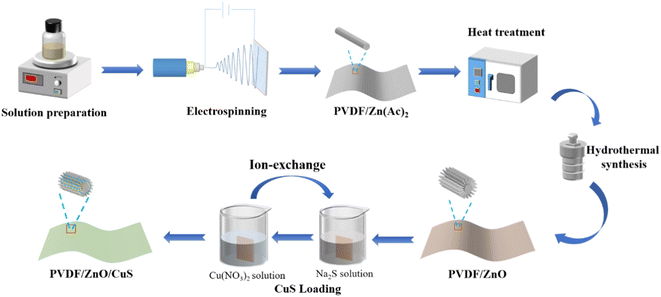
In order to improve the utilization efficiency of solar energy, doping or compositing ZnO with metal, non-metal and other semiconductors are the effective ways to improve the visible-light photocatalytic activity.16–26 CuS is a typical narrow bandgap (1.2–2.0 eV) p-type semiconductor material preferred among visible light photocatalysts due to its low toxicity, simple preparation, and excellent physical and chemical stability.27–38 However, the synthesis of pure CuS nanoparticles demands high pressure and temperature, which to some extent restricts their further use in commercial development. For example, Huang et al. prepared TiO/CuS photocatalytic composites with cauliflower-like shapes using a one-step hydrothermal method, which can effectively remove RhB pollutants by avoiding complex high-temperature calcination and complicated post-treatment.39 Besides, Basu et al. combined a low-temperature wet-chemical method to fabricate ZnO/CuS type-II semiconductor photocatalysts. The generated composite photocatalysts had a 2.5 times higher catalytic efficiency than pure CuS under visible light irradiation.41 Similarly, Kaushik et al. prepared Fe3O4@SiO@ZnO–CuS composited photocatalysts with magnetic core–shell structure, and the degradation rates of methyl blue and toluidine blue were 93% and 87.5%, respectively.36 The disadvantage of the aforementioned composite photocatalysts is still that they are difficult to recover from the photocatalytic reaction in aqueous solution since their finished products are in the form of powder and particles. Previous findings claim that it is possible to load photocatalysts onto inorganic materials with a high specific surface area.42–44 Accordingly, the p–n heterojunction prepared by coupling CuS and ZnO nanomaterials can significantly improve the catalytic activity of ZnO under visible light irradiation.45–47 In addition, in order to make the photocatalysts recyclable and reusable, electrospun nanofibers acting as a base material for mounting nanocomposite photocatalysts are drawing numerous interests.48–50 Despite the fact that nano-powder photocatalysts demonstrate higher photocatalytic efficiency than membranes due to their large specific surface area, there are still many problems in practical applications.51–53 For example, nano-powder photocatalysts are prone to agglomerate, which significantly lowers the light absorption efficiency and reduce the surface area in contact with the pollutant, leading to a decreased photocatalytic activity. Furthermore, after water purification, the subsequent separation process of the photocatalysts is complicated, energy-consuming, hard to recycle, and easy to form potential secondary contamination. Thus, we speculate that heterojunction ZnO/CuS photocatalytic composites anchored to electrostatically spun nanofilms can enhance photocatalytic activity when exposed to visible light and provide more photocatalytic active sites as well as excellent morphological stability for contaminant degradation during continuous water treatment. In order to prevent reactive oxygen species from interfering with the photocatalytic process, the matrix material utilized as an anchor for the photocatalyst must be both physically and chemically stable. According to reports, a variety of materials have been considered photocatalytic carriers (polymers, ceramics, alumina, activated carbon, etc.).54,55 The excellent electrochemical, mechanical, heat-resistance, and chemical stability of polyvinylidene fluoride. However, a substance that is frequently employed in polymer membranes, makes PVDF nanofiber membranes the perfect photocatalytic carrier.56,57 ZnO nanorods were grown on PVDF nanofibers by electrostatic spinning using a mixture of PVDF and zinc acetate, sequentially by heat treatment at temperatures below 200 °C and by the simple hydrothermal method in the growth solution. Compared with direct hydrothermal growth, the simple hydrothermal method has superior ZnO binding fastness, the materials are simple and the conditions are mild, without further reaction at high temperature or high-pressure situations.
In this work, a novel heterostructured composite photocatalyst was prepared by loading ZnO/CuS heterojunction on electrospun PVDF nanofiber membranes by a combination of electrospinning, hydrothermal and ion exchange technique. This method anchors ZnO nanorods on PVDF nanofibers to provide abundant reactive sites for photocatalysis. Meanwhile, CuS, which forms a p–n heterojunction with ZnO nanorods, acts as a photosensitizer to compensate for the low quantum efficiency of ZnO and improves the photocatalytic efficiency under visible light irradiation. The results show that the kinetic constants of PVDF/ZnO/CuS nanocomposites under UV (9.01 min−1) and visible light (6.53 × 10⁻³ min−1) irradiation are 3.66 and 2.53 times higher than those of PVDF/ZnO (2.46 × 10⁻³ min−1 and 2.58 × 10⁻³ min−1), respectively. In addition, this excellent structural stability and recyclability allow the composites to be used in water treatment with long-term integrity and excellent photocatalytic activity.
2. Experimental section
2.1 Materials
Polyvinylidene fluoride powder (PVDF, average molecular weight = 700![[thin space (1/6-em)]](https://www.rsc.org/images/entities/char_2009.gif) 000 g mol−1), N,N-dimethylformamide (DMF), acetone, anhydrous zinc acetate (Zn(Ac)2), hexamethylenetetramine (HMTA), zinc chloride (ZnCl2), ammonia (NH3·H2O), copper(II) nitrate hydrate (Cu(NO3)2·3H2O), sodium sulfide nonahydrate (Na2S·9H2O), sodium hydroxide (NaOH), methylene blue (MB), were purchased from Aladdin Co., Ltd. All reagents are used as is, without further purification.
000 g mol−1), N,N-dimethylformamide (DMF), acetone, anhydrous zinc acetate (Zn(Ac)2), hexamethylenetetramine (HMTA), zinc chloride (ZnCl2), ammonia (NH3·H2O), copper(II) nitrate hydrate (Cu(NO3)2·3H2O), sodium sulfide nonahydrate (Na2S·9H2O), sodium hydroxide (NaOH), methylene blue (MB), were purchased from Aladdin Co., Ltd. All reagents are used as is, without further purification.
2.2 Synthesis method
The electrospun PVDF nanofiber membrane (0.1 g) was put into the 0.1 M growth solution consisting of 1.39 g ZnCl2, 1.42 g HMTA and 5 mL NH3·H2O and appropriate amount 100 g deionized water, and the hydrothermal reaction was completed by growth at 90 °C for 3 h. Finally, the nanofibers were repeatedly washed with deionized water for 3 times and dried, obtaining ZnO@PVDF nanofiber membrane.
2.3 Characterizations
The morphology of nanocomposites was analyzed by scanning electron microscope (SEM) images were taken using a FESEM, ZEISS Gemini 300 field emission scanning electron microscope. Morphological, dimensional and compositional observation of samples using JEOL JEM-2100HR transmission electron microscope with energy spectrum EDS. Using a Rigaku Ultima IV X-ray diffractometer, X-ray diffraction (XRD) maps of the sample structure were taken, studied, and analyzed, and to analyze the surface chemical composition of the substance, measurements were made using a Thermo Scientific K-Alpha+ X-ray energy spectrometer (XPS). Utilizing BaSO4 as the reference material, the diffuse reflectance spectra (DRS) of the materials were measured using a Shimadzu UV-2600 spectrophotometer. Lastly, the photoluminescence spectra (PL) of the prepared sample films were obtained using a Cary Eclipse fluorescence spectrometer at an excitation wavelength = 325 nm.2.4 Photocatalytic measurements
Photocurrent measurements were carried out using a computer-controlled electrochemical workstation (CS-320H). 4 cm × 4 cm PVDF/ZnO/CuS nanofibers were placed in a 50 mL MB solution at a concentration of 20 mg L−1 for a period of time in the dark, and their adsorption properties were tested every 30 min until the adsorption equilibrium was reached. The nanofibers were placed under UV light (UV lamp, 6 W) and visible light (xenon lamp with a 420 nm UV-light cut-off filter, 600 W) simulating the intensity of sunlight, and the supernatant was taken and diluted at certain time intervals, and the residual MB content was determined by using Pu-analysis TU-180 spectrophotometer. A 30 mL solution of MB at a concentration of 10 mg L−1 was selected for the cyclic experiments.3. Results and discussion
The morphology of nanofibers before and after hydrothermal treatment was analyzed by scanning electron microscopy (SEM) (Fig. 2). The morphology of PVDF nanofibers before hydrothermal treatment is relatively smooth, and the diameter of each nanofiber is ∼300 nm (Fig. 2a), but the diameter distribution is not very uniform. After the hydrothermal reaction, the surface of PVDF nanofibers has a large number of neatly arranged ZnO nanowhiskers (Fig. 2b), which envelop the nanofibers entirely and increase their specific surface area significantly. Following that, in situ reductions evenly distribute the CuS nanoparticles on the ZnO nanorods (Fig. 2c). Due to the hydrophobic nature of PVDF, small amounts of CuS nanoparticles are also attached to the PVDF nanofibers in the absence of the intermediate ZnO nanorods, which often form particles with size ranging from a few nanometers to a few micrometers (Fig. S1†). ZnO is n-type semiconductor material, while CuS is a typical narrow bandgap (1.2–2.0 eV) p-type semiconductor material among visible light photocatalysts. Thus, the p–n heterojunction prepared by coupling CuS and ZnO nanomaterials can significantly improve the catalytic activity of ZnO under visible light irradiation. As displayed in TEM images, the crystal spacings of 0.282 nm and 0.305 nm are corresponding to (100) crystal plane of ZnO (wurtzite-type) and (102) crystal plane of CuS (Fig. 2d and e). And the interface between ZnO and CuS marked with red line indicates the successful construction of the p–n heterojunctions (Fig. 2f). Furthermore, the EDS spectral analysis revealed that the Zn, O, Cu, and S elements were homogeneously spread on the surface of the self-grown ZnO nanorods, demonstrating the successful synthesis of ZnO/CuS heterostructures on PVDF nanofibers (Fig. 2g).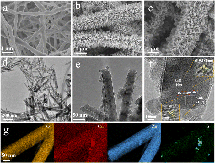 | ||
| Fig. 2 SEM images of (a) PVDF, (b) ZnO@PVDF, (c) PVDF/ZnO/CuS nanocomposites. (d–f) TEM images and (g) EDX mapping of PVDF/ZnO/CuS nanocomposites, respectively. | ||
Fig. 3a represents the XRD spectra of the nanocomposites PVDF/ZnO and PVDF/ZnO/CuS. PVDF/ZnO nanocomposites have typical peaks at 31.6°, 34.3°, 36.1°, 47.4°, 56.5°, 62.7°, 66.3°, 67.8°, 68.9°, 72.5°, and 76.8°, which are related the (100), (002), (101), (102), (110), (103), (200), (112), (201), (004), and (220) of ZnO (JCPDS 36-1451). On the other hand, following of CuS deposition, the diffraction peak at 29.28° is in relatively excellent agreement with the (102) crystal plane of cubic CuS (JCPDS 06-0464), confirming that the PVDF/ZnO/CuS sample consists mainly of CuS and ZnO. The obtained XRD spectra are consistent with the results of TEM, indicating the successful preparation of ZnO/CuS heterojunctions.
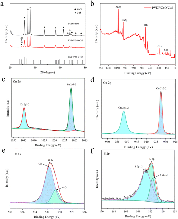 | ||
| Fig. 3 (a) XRD spectrum of PVDF/ZnO, PVDF/ZnO/CuS. (b) XPS spectra of PVDF/ZnO/CuS. High-resolution XPS spectra of (c) Zn 2p, (d) Cu 2p, (e) O 1s, (f) S 2p for PVDF/ZnO/Cus nanocomposites. | ||
Fig. 3b illustrates the XPS spectra of PVDF/ZnO/CuS, exhibiting the presence of Zn, Cu, O and S elements as well as indeterminate carbon. Fig. 3c presents the two characteristic peaks of element Zn. The two peaks at 1021.5 eV and 1044.6 eV correspond to the peaks of Zn 2p3/2 and Zn 2p1/2, respectively. Fig. 3d shows the two peaks at 932.3 eV and 952.2 eV, representing Cu 2p3/2 and Cu 2p1/2, respectively, which correspond to the peaks of Cu in CuS. In Fig. 3e, the O 1s can be divided into two peaks, and the first peak (530.3 eV) is attributed to oxygen in the ZnO structure, which again proves that the prepared nanomaterial is ZnO. The adsorbed water on the sample surface is what is responsible for the second peak (531.7 eV). In Fig. 3f, the major binding energy peaks are positioned at 161.5 eV and 162.4 eV, corresponding to S 2p3/2 and S 2p1/2, respectively. The 0.9 eV band gad between S 2p3/2 and 2p1/2 indicates that Cu element exists in the form of CuS.58,59 These analytical results further demonstrate the presence of heterojunctions ZnO/CuS, which is consistent with the XRD and TEM analyses described above.
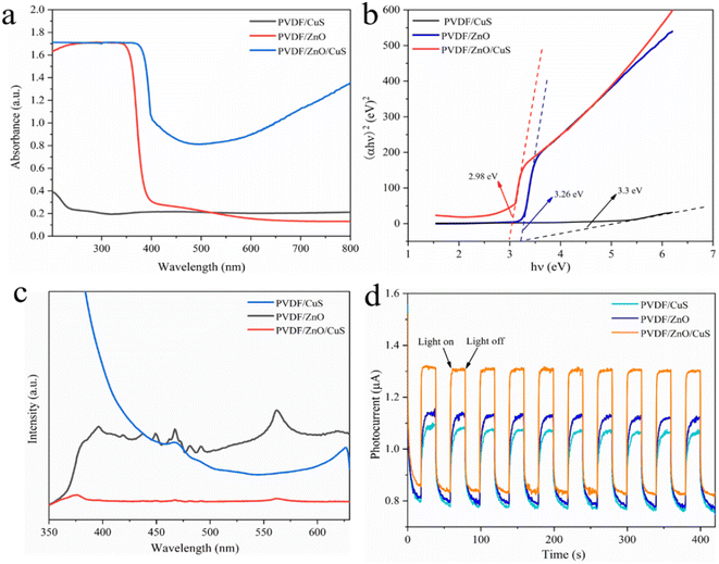
Fig. 4a shows the UV-Vis absorption spectra of the nanocomposites PVDF/CuS, PVDF/ZnO and PVDF/ZnO/CuS, respectively. The PVDF/CuS shows quite low solar light utilization efficiency, which is attributed to that the hydrophobic nature of PVDF results in the attachment of a minority of CuS nanoparticles on PVDF nanofibers. Owing to the wide band gap of ZnO, PVDF/ZnO composites possess superior UV absorption but poor absorption of visible light. After the introduction of CuS, the PVDF/ZnO/CuS nanocomposites show a significant increase in absorption intensity in both UV and visible light regions when compared with PVDF/ZnO, indicating that the strong visible-light sensitive property of CuS. The enhanced 700–800 nm range adsorption could be ascribed to the strong near-infrared light absorption performance of by CuS nanoparticles due to the localized surface plasmon resonance effect.40,60,61 The band gap energy (Eg) of PVDF/CuS, PVDF/ZnO, PVDF/ZnO/CuS can be calculated by the following eqn (1):62
| (αhν)2 = A(hν − Eg) | (1) |
According to the description, α is the absorption coefficient, h is the flat plate constant, v is the optical frequency, A is the constant, and finally, Eg is the band gap energy. The band gap of PVDF/CuS, PVDF/ZnO, and PVDF/ZnO/CuS is calculated as 3.3, 3.26, and 2.98 eV, respectively. Due to the suppression of electron/hole recombination and rapid charge carrier transfer achieved by creating a p–n ZnO/CuS heterojunctions, PVDF/ZnO/CuS has a lower band gap than PVDF/CuS and PVDF/ZnO (Fig. 4b).
The recombination rate of electron–hole pairs can be determined by the photoluminescence (PL) spectra. A lower PL intensity suggests a lower rate of electron–hole pair recombination, which in turn indicates an increase in photocatalytic activity.63 Fig. 4c shows the PL spectra of the PVDF/CuS, PVDF/ZnO, and PVDF/ZnO/CuS nanocomposites. The higher intensity of PVDF/ZnO shows more heterodyne peaks, near-UV emission near 390 nm, corresponding to free exciton emission from the near-band edge of ZnO, and weak blue emission near 467.7 nm, which is caused by the jump of multiple defect states.46,60 The sample shows a broad emission peak near the wavelength of 560 nm in photoluminescence spectra. This broad emission peak has been widely reported for ZnO nanostructures, which can be attributed to OH groups on ZnO surface, electron transition from zinc interstitial or oxygen vacancy to the top of the valence band.9,64 The lower luminescence intensity of PVDF/ZnO/CuS implies a lower degree of recombination of electron–hole pairs when compared to PVDF/ZnO. This phenomenon is attributed to that CuS deposited on the surface of ZnO nanorods traps the photogenerated electrons and inhibits the recombination of electron–hole pairs.
Fig. 4d shows the photocurrent response curves of the nanocomposites PVDF/CuS, PVDF/ZnO, and PVDF/ZnO/CuS under visible light and in the dark. It is obvious that the PVDF/ZnO/CuS nanocomposites with heterostructures have higher photocurrent density under both UV light (1.32 μA cm−2) (Fig. 4d) and visible light (200.71 μA cm−2) (Fig. S3†) irradiation. It is generally accepted that a bigger photocurrent corresponds to a greater number of separated photogenerated carriers. Consequently, the creation of ZnO/CuS heterojunction effectively boosted the electron–hole pairs separation and transfer, enhancing the photocatalytic activity under both UV and visible light irradiation. Consequently, the creation of ZnO/CuS heterojunction effectively boosted the electron–hole pairs separation and transfer, enhancing the photocatalytic activity. After 200 s of UV and visible light irradiation, the PVDF/ZnO/CuS nanocomposite with a heterogeneous architecture can repeatedly create a steady photocurrent without appreciable declining photocurrent. Due to the small quantity and uneven allocation of CuS nanoparticles on PVDF nanofibers, the photocurrent density of PVDF/CuS is substantially lower than that of PVDF/ZnO.
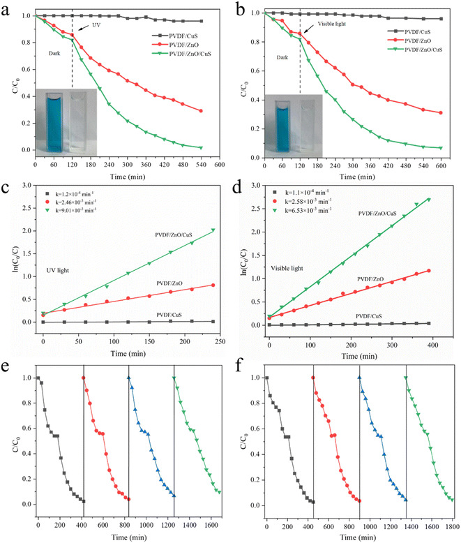
To assess the photocatalytic efficiency of the prepared PVDF/ZnO/CuS nanocomposites against organic pollutants, MB was utilized as a model. Under the same conditions, the photocatalytic activities of PVDF/CuS and PVDF/ZnO are evaluated as a control. Fig. 5a shows that all photocatalysts reached adsorption–desorption equilibrium after about 120 minutes in the dark, with the PVDF/CuS composites showing almost no adsorption performance, whereas the adsorption capacity of PVDF/ZnO and PVDF/ZnO/CuS samples reached 14.2% and 18%, respectively, because the one-dimensional ZnO nanorods and CuS nanoparticles increased the specific surface area and enhanced the hydrophilicity for MB adsorption. PVDF/CuS samples has essentially no photocatalytic efficacy against MB dye after 420 minutes of UV irradiation, while PVDF/ZnO/CuS had a degradation rate of 98.4%, which is much greater than PVDF/ZnO (71.1%). It suggests that the heterojunction of ZnO/CuS increases the photocatalytic degrading performance for MB. In addition, the degrading properties of PVDF/CuS, PVDF/ZnO, and PVDF/ZnO/CuS nanocomposites against MB are also examined under visible light irradiation (Fig. 5b). When exposed to visible light for 480 minutes, the deterioration rates of the PVDF/CuS, PVDF/ZnO, and PVDF/ZnO/CuS nanocomposites were 3.7%, 69%, and 93.3%, respectively. As a consequence, the creation of p–n heterostructures enhances visible light absorption and improves the effective separation and rapid transfer of charge carriers.
Fig. 5c and d depicts a kinetic plot of methyl blue photodegradation by PVDF/ZnO/CuS nanocomposite photocatalyst, which is calculated by the following equation:
 | (2) |
The photodegradation MB mechanism of the PVDF/ZnO/CuS nanocomposites is studied under UV and visible light irradiation. As shown in Fig. 6a. Under UV light irradiation, both ZnO and CuS can be excited to produce photogenerated electrons (e−) and holes (h+). The combination of ZnO and CuS allows electrons to flow from the CuS conduction band to the ZnO conduction band, where they are trapped by oxygen to create superoxide anions (˙O2−). While holes (h+) transport from the valence band (VB) of ZnO to the valence band (VB) of CuS, which combines with H2O to create reactive oxygen species (˙OH). ˙OH and ˙O2− are the main important reactive chemicals for degrading MB. Consequently, the p–n heterojunction significantly limits charge recombination and enhances the composites photocatalytic activity.41,46,58,65,66 Meanwhile, the visible light-induced photodegradation of MB is also investigated. According to Fig. 6b, under visible light irradiation, only CuS can produce photoelectrons, while ZnO cannot produce photoelectrons. The electrons will migrate to the conduction band of ZnO, which eventually leads to the accumulation of holes on CuS. The holes then react with H2O to produce reactive oxygen species, at the same time, the interaction of electrons and oxygen produces superoxide anions that are capable of breaking down organic matter into carbon dioxide and water. Consequently, the p–n heterojunctions greatly boosts photogenerated charge separation/transfer and enhances the photocatalytic activity of PVDF/ZnO/CuS photocatalysts under both UV and visible light irradiation.
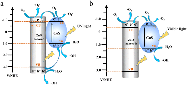 | ||
| Fig. 6 Schematic diagram of mechanism degradation for PVDF/ZnO/CuS nanocomposite fibers under (a) UV and (b) visible light irradiation. | ||
4. Conclusions
In summary, we have developed a new strategy to anchor p–n ZnO/CuS heterojunctions on electrospun PVDF nanofiber membranes via electrospinning, hydrothermal, and ion-exchange techniques. Three-dimensional PVDF nanofiber membranes with high specific surface area provide a large number of loading sites for photocatalysts, and the generation of solid ZnO nanorods on PVDF nanofibers by heat treatment and simple hydrothermal methods, as well as subsequent loading of Cus nanoparticles on shape-regular ZnO nanorods by ion exchange under mild conditions, result in the formation of composites with higher specific surface area. The hierarchical structure with high specific surface area provides more active sites for the photodegradation of MB, while the ZnO/CuS heterojunction extended the visible-light photoresponse range and enhanced the separation/transfer of photogenerated carriers, which considerably improved the photocatalytic activity of ZnO. As a result, the PVDF/ZnO/CuS composited photocatalysts deliver superior photocatalytic performance in exposure to UV and visible light owing to boosted charge carrier separation/transportation and expanded visible light absorption range. The kinetic constants of PVDF/ZnO/CuS nanocomposites under UV irradiation (9.01 × 10⁻³ min−1) and visible light (6.53 × 10⁻³ min−1) irradiation were 3.66 and 2.53 times higher than that of PVDF/ZnO (2.46 × 10⁻³ min−1 & 2.58 × 10⁻³ min−1), respectively. Moreover, PVDF/ZnO/CuS nanocomposites exhibit high stability after recycling and reusing, which provides a new strategy for designing recyclable novel heterogeneous semiconductor catalysts load on nanofiber membrane in the field of photocatalytic degradation of pollutants, hydrogen production by water splitting.Author contributions
G. Zhang, M. Ge and W. Zhang conceived the project and designed the experiments. C. Zang, H. Chen, X. Han, J. Wu and F. Liang fabricated the samples, conducted the characterizations and performed the battery tests. G. Zhang, Q. Zhang, M. Ge and W. Zhang revised the manuscript. All authors analyzed the data and contributed to the discussions.Conflicts of interest
The authors declare they have no conflicts interest.Acknowledgements
This work was funded by the National Natural Science Foundation of China (No. 52202256), Natural Science Foundation of Jiangsu Province of China (BK20220612). We also acknowledge the funds from the project of Jiangsu University “Qinglan Project”. This work was also supported by the Opening Project of Jiangsu Engineering Research Centre of Textile Dyeing and Printing for Energy Conservation, Discharge Reduction and Cleaner Production, Soochow University (No. SDGC2102) and Science and Technology Development Fund, Macau SAR (File No. 0092/2019/A2, and 0035/2019/AMJ).Notes and references
- A. Dhakshinamoorthy, A. M. Asiri and H. Garcia, Adv. Mater., 2019, 31, 1900617 CrossRef CAS.
- M. Xiao, Z. Wang, M. Lyu, B. Luo, S. Wang, G. Liu, H. M. Cheng and L. Wang, Adv. Mater., 2019, 31, 1801369 CrossRef PubMed.
- Z. Tong, D. Yang, T. Xiao, Y. Tian and Z. Jiang, Chem. Eng. J., 2015, 260, 117–125 CrossRef.
- W. Jiang, J. Low, K. Mao, D. Duan, S. Chen, W. Liu, C. W. Pao, J. Ma, S. Sang, C. Shu, X. Zhan, Z. Qi, H. Zhang, Z. Liu, X. Wu, R. Long, L. Song and Y. Xiong, J. Am. Chem. Soc., 2021, 143, 269–278 CrossRef.
- Y. Miseki and K. Sayama, Adv. Energy Mater., 2018, 9, 1801294 CrossRef.
- B. Puértolas, M. Comesaña-Hermo, L. V. Besteiro, M. Vázquez-González and M. A. Correa-Duarte, Adv. Energy Mater., 2022, 12, 2103909 CrossRef.
- Y. Liu, J. Liu, Q. Zhang, Q. Zhu, X. Liu, Z. Wang and Z. J. A. F. M. Dai, Adv. Funct. Mater., 2022, 32, 2106854 CrossRef.
- J. H. Sun, S. Y. Dong, J. L. Feng, X. J. Yin and X. C. Zhao, J. Mol. Catal. A: Chem., 2011, 335, 145–150 CrossRef.
- A. Das, M. Patra, M. Kumar P, M. Bhagavathiachari and R. G. Nair, J. Alloys Compd., 2021, 858, 157730 CrossRef.
- Q. Fan, T. Wang, W. Fan and L. J. C. C. Xu, Compos. Comm., 2022, 32, 101154 CrossRef.
- S. S. Shinde, C. H. Bhosale and K. Y. Rajpure, J. Photochem. Photobiol., B, 2012, 113, 70–77 CrossRef.
- S. Danwittayakul, M. Jaisai and J. Dutta, Appl. Catal., B, 2015, 163, 1–8 CrossRef.
- R. Kumar, A. Umar, G. Kumar, M. S. Akhtar, Y. Wang and S. H. Kim, Ceram. Int., 2015, 41, 7773–7782 CrossRef.
- H. Zhai, L. Wang, D. Sun, D. Han, B. Qi, X. Li, L. Chang and J. Yang, J. Phys. Chem. Solids, 2015, 78, 35–40 CrossRef.
- N. Elavarasan, S. Vignesh, M. Srinivasan, G. Venkatesh, G. Palanisamy, P. Ramasamy, B. Palanivel, A. M. Al-Enizi, M. Ubaidullah, V. R. Minnam Reddy and W. K. Kim, J. Alloys Compd., 2022, 906, 164255 CrossRef.
- R. Cai, J. G. Wu, L. Sun, Y. J. Liu, T. Fang, S. Zhu, S. Y. Li, Y. Wang, L. F. Guo, C. E. Zhao and A. Wei, Mater. Des., 2016, 90, 839–844 CrossRef.
- F. Chen, Y. Tang, C. Liu, J. Qian, Z. Wu and Z. Chen, Ceram. Int., 2017, 43, 14525–14528 CrossRef.
- N. A. Galedari, M. Rahmani and M. Tasbihi, Environ. Sci. Pollut. Res., 2017, 24, 12655–12663 CrossRef PubMed.
- N. Elamin, A. Modwi, M. Aissa, K. Taha, O. Al-Duaij and T. Yousef, J. Mater. Sci.: Mater. Electron., 2021, 32, 2234–2248 CrossRef.
- M. Al-Gharibi, H. Kyaw, J. Al-Sabahi, M. Myint, Z. Al-Sharji and M. Al-Abri, Mater. Sci. Semicond. Process., 2021, 134, 105994 CrossRef.
- M. Uddin, M. Hoque and M. Bhoumick, RSC Adv., 2020, 10, 23554–23565 RSC.
- C. Feng, Z. Chen, J. Jing and J. Hou, J. Mater. Chem. C, 2020, 8, 3000–3009 RSC.
- S. Suwanboon, P. Amornpitoksuk and C. Random, Ceram. Int., 2019, 45, 2111–2116 CrossRef.
- Y. Liu, H. Liu, H. Zhou, T. Li and L. Zhang, Appl. Surf. Sci., 2019, 466, 133–140 CrossRef.
- F. Khurshid, M. Jeyavelan, M. Hudson and S. Nagarajan, R. Soc. Open Sci., 2019, 6, 181764 CrossRef PubMed.
- E. Benavente, F. Duran, C. Sotomayor-Torres and G. Gonzalez, J. Phys. Chem. Solids, 2018, 113, 119–124 CrossRef.
- Q. Chen, S. Wu and Y. Xin, Chem. Eng. J., 2016, 302, 377–387 CrossRef.
- T. Ung Thi Dieu, L. Nguyen Quang, C. M. A. Parlett, G. M. Lalev and K. Wilson, Catal. Commun., 2014, 44, 62–67 CrossRef.
- X. Guan, P. Qu, X. Guan and G. Wang, RSC Adv., 2014, 4, 15579–15585 RSC.
- X. Hu, Y. Shen, L. Xu, L. Wang and Y. Xing, J. Alloys Compd., 2016, 674, 289–294 CrossRef.
- Y. Lu, Y. Zhang, J. Zhang, Y. Shi, Z. Li, Z. Feng and C. Li, Appl. Surf. Sci., 2016, 370, 312–319 CrossRef.
- Z. Cai, Y. Zhou, S. Ma, S. Li, H. Yang, S. Zhao, X. Zhong and W. Wu, J. Photochem. Photobiol., A, 2017, 348, 168–178 CrossRef.
- V. Sharma and P. Jeevanandam, J. Nanosci. Nanotechnol., 2020, 20, 5223–5238 CrossRef.
- J. Hou, B. Huang, L. Kong, Y. Xie, Y. Liu, M. Chen and Q. Wang, Ceram. Int., 2021, 47, 30860–30868 CrossRef.
- E. Valadez-Renteria, E. Barrera-Rendon, J. Oliva and V. Rodriguez-Gonzalez, Sep. Purif. Technol., 2021, 270, 118821 CrossRef.
- B. Kaushik, S. Yadav, P. Rana, P. Rana, K. Solanki, D. Rawat and R. K. Sharma, Appl. Surf. Sci., 2022, 590, 153053 CrossRef.
- Y. Wang, Q. Liu, N. Wong, J. Sunarso, J. Huang, G. Dai, X. Hou and X. Li, Ceram. Int., 2022, 48, 2459–2469 CrossRef.
- L. Yan, W. Wang, Q. Zhao, Z. Zhu, B. Liu and C. Hu, J. Colloid Interface Sci., 2022, 606, 898–911 CrossRef.
- S. Huang, C. Qin, L. Niu, J. Wang, J. Sun and L. Dai, New J. Chem., 2022, 46, 10594–10602 RSC.
- C. Lai, M. Zhang, B. Li, D. Huang, G. Zeng, L. Qin, X. Liu, H. Yi, M. Cheng, L. Li, Z. Chen and L. Chen, Chem. Eng. J., 2019, 358, 891–902 CrossRef.
- M. Basu, N. Garg and A. K. Ganguli, J. Mater. Chem. A, 2014, 2, 7517–7525 RSC.
- L. Liu, D. Wang, J. Huang, Z. Huang, Y. Zhang and L. Li, ACS Omega, 2022, 7, 17128–17143 CrossRef.
- Y. Xing, J. Cheng, H. Li, D. Lin, Y. Wang, H. Wu and W. Pan, Nanomaterials, 2021, 11, 3221 CrossRef.
- L. G. Peng, F. R. Ni, J. Liu, M. Sun, M. J. Chang, T. Xi, H. L. Li, H. L. Du, J. Yang and Y. Li, J. Mater. Sci.: Mater. Electron., 2021, 32, 20891–20902 CrossRef.
- S. Harish, J. Archana, M. Navaneethan, S. Ponnusamy, A. Singh, V. Gupta, D. K. Aswal, H. Ikeda and Y. Hayakawa, RSC Adv., 2017, 7, 34366–34375 RSC.
- T. Zhao, Q. Wang and A. Du, Mater. Lett., 2021, 294, 129752 CrossRef CAS.
- R. Li, H. Ma, J. Shu, Z. Lian, N. Chen, S. Ou, R. Jin, S. Li and H. Yang, J. Colloid Interface Sci., 2021, 604, 198–207 CrossRef CAS.
- J. Guo, D. Y. S. Yan, F. L. Y. Lam, B. J. Deka, X. Lv, Y. H. Ng and A. K. An, Chem. Eng. J., 2019, 378, 122137 CrossRef CAS.
- Z. G. Zhang, H. Liu, X. X. Wang, J. Zhang, M. Yu, S. Ramakrishna and Y. Z. Long, Nanomaterials, 2019, 9, 431 CrossRef CAS PubMed.
- S. Li, Z. Cui, D. Li, G. Yue, J. Liu, H. Ding, S. Gao, Y. Zhao, N. Wang and Y. Zhao, Compos. Comm., 2019, 13, 1–11 CrossRef.
- A. E. Shalan, M. Afifi, M. M. El-Desoky and M. K. Ahmed, New J. Chem., 2021, 45, 9212–9220 RSC.
- P. Teng, Z. Li, S. Gao, K. Li, N. Copner, L. Zhihai and X. Yang, Opt. Mater. Express, 2022, 12, 1031–1042 CrossRef.
- Y. Bai, X. Mao, J. Song, X. Yin, J. Yu and B. Ding, Compos. Comm., 2017, 5, 13–18 CrossRef.
- E. M. Sitinjak, I. Masmur, N. V. M. D. Marbun, P. E. Hutajulu, G. Gultom and Y. Sitanggang, RSC Adv., 2022, 12, 16165–16173 RSC.
- Z. Mao, R. Xie, D. Fu, L. Zhang, H. Xu, Y. Zhong and X. Sui, Sep. Purif. Technol., 2017, 176, 277–286 CrossRef.
- N. Rosman, W. N. W. Salleh, F. Aziz, A. F. Ismail, Z. Harun, S. S. Bahri and K. Nagai, Catalysts, 2019, 9, 565 CrossRef.
- R. Kumar, R. Singh, M. Singh and P. Kumar, J. Manuf. Process., 2020, 60, 268–282 CrossRef.
- P. Liu, Y. Huang, J. Yan, Y. Yang and Y. Zhao, ACS Appl. Mater. Interfaces, 2016, 8, 5536–5546 CrossRef.
- M. Lee and K. Yong, Nanotechnology, 2012, 23, 194014 CrossRef.
- D. Hong, W. Zang, X. Guo, Y. Fu, H. He, J. Sun, L. Xing, B. Liu and X. Xue, ACS Appl. Mater. Interfaces, 2016, 8, 21302–21314 CrossRef.
- C. Coughlan, M. Ibanez, O. Dobrozhan, A. Singh, A. Cabot and K. M. Ryan, Chem. Rev., 2017, 117, 5865–6109 CrossRef.
- M. Shkir, M. Anis, S. S. Shaikh and S. AlFaify, Superlattices Microstruct., 2019, 133, 106202 CrossRef.
- Y. Bao, H. Guo, L. Jiang, Z. Liu, J. Qu, C. Zhang, X. Jia and K. Chen, Appl. Surf. Sci., 2019, 496, 143639 CrossRef.
- S. Shi, J. Xu and L. Li, Main Group Chem., 2017, 16, 47–55 Search PubMed.
- Z. Ru, X. Zhang, M. Zhang, J. Mi, C. Cao, Z. Yan, M. Ge, H. Liu, J. Wang, W. Zhang, W. Cai, Y. Lai and Y. Feng, Environ. Sci. Technol., 2022 DOI:10.1021/acs.est.2c04193.
- F. Chen, H. Huang, L. Guo, Y. Zhang and T. Ma, Angew. Chem. Int. Ed., 2019, 58, 10061–10073 CrossRef.
Footnote |
| † Electronic supplementary information (ESI) available. See DOI: https://doi.org/10.1039/d2ra06151a |
| This journal is © The Royal Society of Chemistry 2022 |

