 Open Access Article
Engineering of metal–organic framework nanomaterials on long-period fiber grating for acetone vapor sensing
Haishi Wang*ac,
Guowei Deng *bc,
Lianghai Dongc,
Ke Zhaoc,
Kaixin Chenc,
Kin Seng Chiang*d and
Jieyun Wu
 *c
*c
aCollaborative Innovation Center of Integrated Computation and Chip Security, Chengdu University of Information Technology, Chengdu, China. E-mail: whs@cuit.edu.cn
bCollege of Chemistry and Life Science, Sichuan Provincial Key Laboratory for Structural Optimization and Application of Functional Molecules, Chengdu Normal University, Chengdu, China. E-mail: guoweideng86@163.com
cSchool of Optoelectronic Science and Engineering, University of Electronic Science and Technology of China, Chengdu, China. E-mail: jieyunwu@uestc.edu.cn
dDepartment of Electrical Engineering, City University of Hong Kong, Hong Kong, China. E-mail: eeksc@cityu.edu.hk
First published on 25th November 2022
Abstract
Metal–organic framework (MOF) material is one of the most promising porous nanomaterials for volatile organic compound (VOC) adsorption and sensing. The large surface area and the high porosity of MOF contribute to the high sensitivity of MOF-based VOC sensors. In this study, we engineer the coating of the zeolitic imidazolate framework material ZIF-8 grown on the surface of a long-period fiber grating (LPFG) for acetone vapor sensing. Being a periodic structure formed in a single-mode optical fiber, an LPFG is designed to couple light from the core to the cladding of the fiber at a specific resonance wavelength. Adsorption of acetone vapor molecules in the framework of the ZIF-8 coating can change the refractive index of the coating and cause a shift in the resonance wavelength of the LPFG. The sensitivity of the resonance shift of the LPFG to the acetone vapor concentration depends strongly on the thickness of the ZIF-8 coating. To create a dense ZIF-8 coating, at least five growth cycles of ZIF-8 (30 min growth for one cycle) are required, and nine growth cycles can create a 500 nm thick coating. The LPFG coated with nine growth cycles of ZIF-8 provides a high sensitivity of 21.9 nm ppm−1, a low detection limit of 1.4 ppm, and a wide detection range of about 1500 ppm. Our results can facilitate the development of high-performance optical fiber sensors based on MOF for VOC detection.
Introduction
Metal–organic frameworks (MOFs), which are formed with metal ions and organic ligands into a coordination pattern, have attracted a wide interest as a new class of porous crystalline materials.1 Compared with porous organic polymers and porous carbon materials, MOFs have large surface area, highly ordered pore structure, and structural diversity and tunability.2 These unique advantages allow strong host–guest interactions within the framework and, thus, make MOFs highly suitable as sensitive materials for the separation and the detection of gases or volatile organic compound (VOC) vapors.3–5 Zeolitic imidazolate frameworks (ZIFs) are a subclass of MOFs that are synthesized by coordination of zinc or cobalt with imidazole. ZIF-8, which consists of 2-methylimidazole and Zn2+ ions, is one of the representative structures.6 Owing to its large surface area (1946 m2 g−1), high porosity, and excellent mechanical, thermal, and chemical stability, ZIF-8 is widely used for VOC adsorption and sensing.7 ZIF-8 based fluorescent sensors, microbalance sensors, electrochemical sensors, and optical fiber/waveguide sensors have been developed for highly sensitive and rapid detection of various toxic and hazardous vapors, such as formaldehyde, explosives, aromatic hydrocarbons, etc.8–19Compared with traditional sensors, optical fiber sensors (OFSs), which employ optical fibers to achieve sensing with light, can offer a number of unique advantages, such as absolute electrical insulation, immunity to electromagnetic interference, non-invasiveness, corrosion resistance, and high sensitivity. OFSs also allow long-distance monitoring and interrogation of sensors. Among different types of structures, OFSs based on the structure of long-period fiber grating (LPFGs) offer additional advantages, in particular, wavelength-encoded sensing and wavelength-multiplexing capability.20 An LPFG is a structure formed in a single-mode fiber by introducing a periodic modulation of the refractive index along the fiber with a period of the order of hundreds of micrometers.21 Such a structure allows the guided core mode to be coupled to the cladding modes of the fiber at specific resonance wavelengths, which results in a series of rejection bands in the transmission spectrum of the fiber. Perturbations in the refractive index of the surrounding medium can change the propagation characteristics of the cladding modes and shift the resonance wavelengths of the LPFG. Therefore, an LPFG coated with an effective adsorptive film can measure the refractive index change of the film caused by the adsorbed guest and hence function as a selective sensor. In fact, such LPFG sensors have been demonstrated for the detection of various chemical and biological substances.22–24
The MOF nanotechnology provides more opportunities for the development of new OFSs,25,26 in particular, for VOC sensing.27 The interaction of MOF material with VOC molecules can lead to a significant change in the refractive index of the material,28–30 which allows VOC to be sensitively detected in OFSs. Optical fiber Fabry-Perot cavities integrated with ZIF-8, HKUST-1, and Uio-66 for the detection of VOC, explosive, and carbon dioxide, as well as rhodamine-B in aqueous solutions, have been reported.31–34 Mach–Zehnder interferometric OFSs covered with graphene-oxide nickel MOF and ZIF-8 have been demonstrated for sensitive detection of hydrogen and ethanol.35 LPFGs coated with different MOFs have been proposed for VOC sensing, but their performances in terms of sensitivity and detection limit still need further optimization to achieve ultra-sensitive detection.36,37
In this paper, we report our study on engineering the ZIF-8 coating of an LPFG sensor for acetone vapor sensing. In particular, we study how an LPFG coated with different growth cycles of ZIF-8 affects its performance as an acetone vapor sensor. We show that nine growth cycles of ZIF-8 (30 min growth for one cycle) can form a 500 nm thick ZIF-8 coating and the coated LPFG can achieve a high detection sensitivity of 21.9 pm ppm−1 and a low detection limit of 1.4 ppm over a detection range of ∼1500 ppm. The use of a sufficiently thick ZIF-8 coating can greatly enhance the performance of an LPFG sensor for VOC detection.
Results and discussion
Design and fabrication of long-period fiber grating (LPFG)
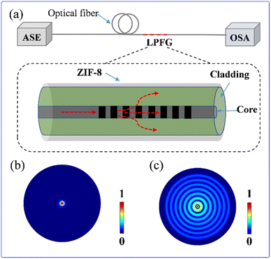
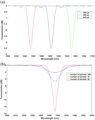
The LPFG sensing system is illustrated in Fig. 1a. The surface of LPFG is coated with ZIF-8 nanomaterials. Light from an amplified spontaneous emission (ASE) source (B&A Technology, AS4600) is launched into the fiber and transmitted as LP01 core mode. The intensity distribution of the LP01 mode in the fiber is shown in Fig. 1b, which indicates that the LP01 mode is well confined in the core of the fiber. The LPFG in this study is designed to couple the LP01 mode to the LP08 cladding mode of the fiber. The intensity distribution of the LP08 mode in the fiber is shown in Fig. 1c, which indicates that the mode is confined in the entire cladding of the fiber. The transmission spectrum of the fiber is measured with an optical spectrum analyzer (OSA) (Anritsu MS9740A).The resonance wavelength λ0 at which the LP01 mode is coupled most strongly to the LP08 mode is governed by the phase-matching condition:21
| λ0 = (N01 − N08)Λ, | (1) |
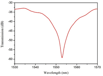
The LPFG is fabricated by a CO2 pulsed laser. The laser irradiation causes residual stress release in the fiber and changes the density of the fiber material and its refractive index.38 The CO2 laser is computer-controlled to periodically scan the fiber along the transverse direction, resulting in a periodic change in the refractive index along the fiber to form a grating structure.38 Fig. 3 shows the measured transmission spectrum of the fabricated LPFG with a period of 320 μm and a length of 100 periods. The resonance wavelength of the LPFG is 1552.83 nm and the extinction ratio is 27 dB. Such high extinction ratio is attributed to careful tuning of the laser power and the exposure time to optimize the mode coupling.38
In situ growth of ZIF-8 on optical fiber
A sensitive ZIF-8 coating needs to be grown on the fabricated LPFG to leverage the large surface area and the high porosity of ZIF-8 for the enrichment of VOC vapor on the fiber. For this purpose, the thickness and the morphology of the ZIF-8 coating are critical. Uniform and densely ordered crystals can facilitate fast adsorption of VOC and thus fast detection. Meanwhile, the thickness of the ZIF-8 coating plays a key role in determining the sensitivity and the response speed of VOC sensing. In our study, one, two, three, five, seven, and nine cycles of in situ growth of ZIF-8 on the fiber, with 30 min growth for one cycle, are performed. The surface morphology of ZIF-8 on fiber is characterized by SEM. The details of the ZIF-8 growth can be found in the Experimental section.The SEM images show that, after one (Fig. 4a and b) and two (Fig. 4c and d) growth cycles, the fiber is not fully covered with ZiF-8 particles. After three growth cycles (Fig. 4e and f), the fiber is mostly covered with ZIF-8 particles, but the particle size is not uniform and most particles are crystal seeds, which suggests that more growth cycles are required. After five growth cycles (Fig. 4g and h), the ZIF-8 particles on the fiber is dense and uniform. Our results indicate that at least five cycles are required to form a dense ZIF-8 coating. The thickness of the ZIF-8 coating after five cycles of in situ growth, measured by a surface step profiler, is 300 ± 30 nm. The thickness of ZIF-8 coating can be further increased with more growth cycles. After seven and nine growth cycles, the thickness of the ZIF-8 coating is increased to 390 ± 20 nm and 500 ± 30 nm, respectively.
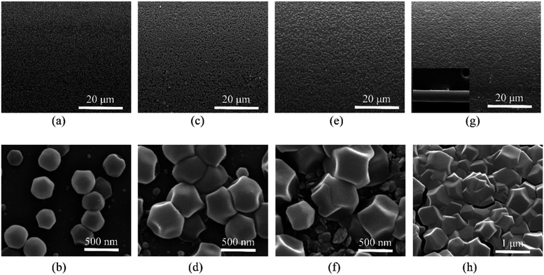 | ||
| Fig. 4 SEM images of the fiber surface after (a, b) one cycle, (c, d) two cycles, (e, f) three cycles, and (g, h) five cycles (inset: bare fiber with a diameter of 125 μm) of in situ growth of ZIF-8. | ||
The thickness of the ZIF-8 coating affects the effective index of the LP08 cladding mode and the resonance wavelength of the LPFG. Fig. 5 shows the measured transmission spectra of the LPFG after different cycles of ZIF-8 growth, which are labelled as LPFG-0, LPFG-3, LPFG-5, LPFG-7, and LPFG-9 for zero, three, five, seven, and nine growth cycles, respectively. As shown in Fig. 5, after three growth cycles, the resonance wavelength shifts from 1552.83 nm to 1550.88 nm. After five growth cycles, a dense uniform ZIF-8 coating is formed and the resonance wavelength shifts to 1546.50 nm. Afterwards, the resonance wavelength shifts towards the shorter wavelength by about 2 nm for every two additional growth cycles. The resonance wavelength after nine growth cycles is 1542.38 nm, with the 10.45 nm shift from the bare LPFG-0 without ZIF-8.
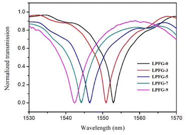 | ||
| Fig. 5 Transmission spectra of the LPFG before ZIF-8 growth (LPFG-0) and after three (LPFG-3), five (LPFG-5), seven (LPFG-7), and nine (LPFG-9) cycles of ZIF-8 growth. | ||
VOC sensing of LPFG
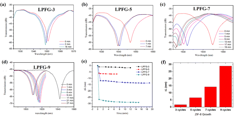
The VOC sensing mechanism is based on the refractive index change of ZIF-8 coating on the surface of optical fiber. Typically, due to the strong during the adsorption. Due to the strong electrostatic interactions, the guest VOC molecules can be easily adsorbed inside the pore of ZIF-8, causing a change in the refractive index of ZIF-8 on the fiber surface; and the light of the LP08 mode excited by the long-period grating senses this change in refractive index in ZIF-8, resulting in a change in the effective refractive index of the LP08 mode, but the effective refractive index of the fundamental mode LP01 in the fiber core layer refractive index does not change. Therefore, according to the phase-matching condition of eqn (1), it is known that the change in refractive index of ZIF-8 corresponds to the change in the resonant center wavelength of the LP08 and LP01 mode coupling of the long-period grating. Different concentrations of VOC adsorption will produce different ZIF-8 refractive index changes, leading to the different resonance center wavelength changes. Therefore, it can correspond to the VOC concentration, so as to quantitatively obtain the gas concentration.To evaluate the effect of the ZIF-8 thickness on the performance of VOC sensing, the VOC adsorption dynamics is firstly monitored. The ZIF-8 coated LPFG is placed in a sealed chamber filled with saturated acetone vapor and the resonance wavelength of the LPFG is measured with the OSA. As the ZIF-8 coating adsorbs acetone molecules, the refractive index of the coating should be increased, which should result in an increase in the effective index of the cladding mode and a blue-shift in the resonance wavelength of the LPFG. The adsorption kinetic process is obtained by recording the variation of the resonance wavelength of the LPFG with time during the adsorption process. Fig. 6a–d show the transmission spectra of LPFG-3, LPFG-5, LPFG-7, and LPFG-9, respectively, measured for different acetone vapor exposure times. Fig. 6e shows the variation of the resonance shift with the exposure time for the LPFG with different cycles of ZIF-8 growth. As shown in Fig. 6e, the ZIF-8 coating responds quickly. For a relatively thin ZIF-8 coating, as in LPFG-3 and LPFG-5, it takes only one to two minutes for the resonance shift to settle. For a thicker ZIF-8, as in LPFG-7 and LPFG-9, most of the resonance shift still occurs in the first two minutes and it takes another five to ten minutes to reach the final value. The fast response can be attributed to the highly ordered porosity of the ZIF-8 coating, which is consistent with previous conclusion on different sensing device with ZIF-8.32,36 Fig. 6f shows the final resonance shifts of the LPFG with different cycles of ZIF-8 growth. After three growth cycles, the distribution of the ZIF-8 particles on the LPFG remains sparse and the adsorption effect causes only a small resonance shift of about 2 nm. After five growth cycles, the ZIF-8 coating becomes denser and the final resonance shift is about 7 nm. After seven growth cycles, the ZIF-8 coating becomes thicker and the final resonance shift is 14.2 nm. After nine growth cycles, the final resonance shift is as large as 28.8 nm. Clearly, a thicker ZIF-8 coating results in a larger wavelength shift and, hence, a higher sensitivity for acetone vapor detection. For a bare LPFG without any ZIF-8 coating, however, the resonance shift is smaller than 0.1 nm in saturated acetone vapor. Our experimental results confirm that the strong adsorption effect in the porous ZIF-8 coating can significantly increase the refractive index of the coating and thus lead to a large blue-shift of the resonance wavelength of the LPFG.
Fig. 7 shows the resonance shifts of LPFG-7 and LPFG-9 measured at different concentrations of acetone vapor in air. The sensitivities for LPFG-7 and LPFG-9, which are the slopes of the fitted straight lines in Fig. 7, are 11.0 pm ppm−1 and 21.9 pm ppm−1, respectively, and their detection ranges are approximately 1200 ppm and 1500 ppm, respectively. The detection range is limited by the saturation of the adsorption effect in the ZIF-8 coating. The detection limit D of the sensor is given by,
| D = R/S, | (2) |
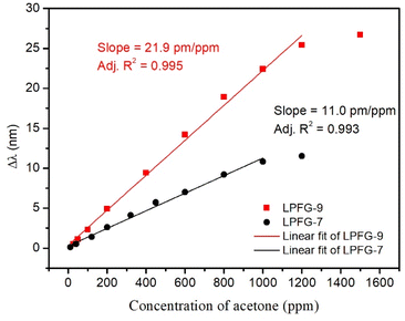 | ||
| Fig. 7 Resonance shifts of LPFG-7 and LPFG-9 measured at different concentrations of acetone vapor in air. | ||
Conclusions
We have studied in detail how the number of growth cycles of ZIF-8 on an LPFG affects the coating quality and the response of the LPFG to acetone vapor. We find that at least five growth cycles are needed for producing a dense ZIF-8 coating and the thickness of the ZIF-8 coating increases further by applying more growth cycles. Our experiments show that the shift in the resonance wavelength of an LPFG properly coated with ZIF-8 can serve as a sensitive measure of the acetone vapor concentration. In particular, our LPFG sensor coated with nine growth cycles of ZIF-8 can provide a high sensitivity (21.9 pm ppm−1) and a wide detection range (∼1500 ppm) for acetone vapor detection. The response time of the LPFG sensor is also short (less than 2 minutes). Our results can facilitate the development of MOF-based optical fiber sensors for VOC detection.Experimental
Materials and instruments
All chemicals were purchased from Sigma-Aldrich and used as received. Optical fiber simulation was performed with a commercial mode solver (COMSOL Multiphysics) based on the full-vector finite-element method and Matlab. Scanning electronic microscopy (SEM) images were collected by Inspect F (FEI). The LPFG was fabricated with a CO2 laser using a well-established procedure.38 The thickness of ZIF-8 on the surface of optical fiber was measured by Dektak 150 step profiler. The refractive index of ZIF-8 film was 1.3724, which was measured by Prism Coupler M2010. And the optical fiber we used is the standard single mode optical fiber. The refractive indices of the core and the cladding of the fiber are 1.452 and 1.444, respectively, and the corresponding diameters are 8.2 μm and 125 μm, respectively.In situ growth of ZIF-8 on LPFG
Zn(NO3)2·6H2O and 2-methyl-imidazole were dissolved in methanol with respective concentration of 12.5 mM and 25 mM. The LPFG was immersed in the mixed solution with a 1![[thin space (1/6-em)]](https://www.rsc.org/images/entities/char_2009.gif) :
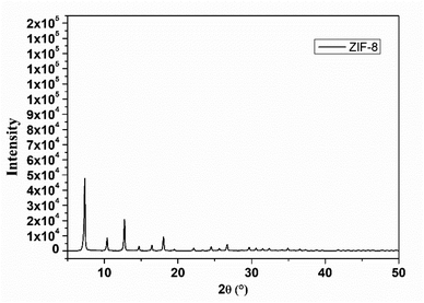
:![[thin space (1/6-em)]](https://www.rsc.org/images/entities/char_2009.gif) 1 volume ratio for 30 min at 25 °C and then washed with methanol for three times. ZIF-8 was grown on the surface of the LPFG and a growth time of 30 min is designated as one growth cycle. After completing a desired number of growth cycles, the LPFG was dried in a vacuum oven at 80 °C overnight to remove any residual solvent. The transmission spectrum of the LPFG was monitored with an OSA to determine its resonance wavelength. The procedure was repeated when the LPFG was coated with additional growth cycles of ZIF-8. Meanwhile, the crystal particles were collected by centrifugation and washed in methanol for three times. The XRD pattern of ZIF-8, as shown in Fig. 8, illustrated the correct diffraction peaks of ZIF-8. Meanwhile, the BET measurement was performed and the measured surface area of ZIF-8 is 1587 m2 g−1, showing the ultra large surface to absorb guest VOC gas.
1 volume ratio for 30 min at 25 °C and then washed with methanol for three times. ZIF-8 was grown on the surface of the LPFG and a growth time of 30 min is designated as one growth cycle. After completing a desired number of growth cycles, the LPFG was dried in a vacuum oven at 80 °C overnight to remove any residual solvent. The transmission spectrum of the LPFG was monitored with an OSA to determine its resonance wavelength. The procedure was repeated when the LPFG was coated with additional growth cycles of ZIF-8. Meanwhile, the crystal particles were collected by centrifugation and washed in methanol for three times. The XRD pattern of ZIF-8, as shown in Fig. 8, illustrated the correct diffraction peaks of ZIF-8. Meanwhile, the BET measurement was performed and the measured surface area of ZIF-8 is 1587 m2 g−1, showing the ultra large surface to absorb guest VOC gas.
Author contributions
Conceptualization: Jieyun Wu, Kin Seng Chiang; funding acquisition: Jieyun Wu, Kaixin Chen; methodology: Haishi Wang, Ke Zhao, Lianghai Dong; investigation: Haishi Wang, Guowei Deng; writing – original draft: Jieyun Wu, Haishi Wang; writing – review & editing: Kin Seng Chiang, Kaixin Chen.Conflicts of interest
There are no conflicts to declare.Acknowledgements
This research is supported in part by the National Natural Science Foundation of China (U20A20165, 62275042) and the Fundamental Research Funds for the Central Universities (ZYGX2019Z005).References
- H. Y. Li, S. N. Zhao, S. Q. Zang and J. Li, Chem. Soc. Rev., 2020, 49, 6364–6401 RSC.
- J. F. Olorunyomi, M. M. Sadiq, M. Batten, K. Konstas, D. H. Chen, C. M. Doherty and R. A. Caruso, Adv. Opt. Mater., 2020, 8, 2000961 CrossRef CAS.
- B. Chocarro-Ruiz, J. Perez-Carvajal, C. Avci, O. Calvo-Lozano, M. I. Alonso, D. Maspoch and L. M. Lechuga, J. Mater. Chem. A, 2018, 6, 13171–13177 RSC.
- A. T. John, K. Murugappan, M. Taheri, D. R. Nisbet and A. Tricoli, J. Mater. Chem. C, 2021, 9, 17331–17340 RSC.
- T. Virdis, C. Walgraeve, A. Ioannidis, H. Van Langenhove and J. F. M. Denayer, J. Environ. Chem. Eng., 2021, 9, 106568 CrossRef CAS.
- K. S. Park, Z. Ni, A. P. Cote, J. Y. Choi, R. D. Huang, F. J. Uribe-Romo, H. K. Chae, M. O'Keeffe and O. M. Yaghi, Proc. Natl. Acad. Sci. U. S. A., 2006, 103, 10186–10191 CrossRef CAS PubMed.
- H. Yuan, N. Li, W. Fan, H. Cai and D. Zhao, Adv. Sci., 2021, 9, 2104374 CrossRef PubMed.
- H. M. Zhao, X. J. Li, W. Z. Li, P. Wang, S. Chen and X. Quan, RSC Adv., 2014, 4, 36444–36450 RSC.
- D. Z. Shen, T. T. Cai, X. L. Zhu, X. L. Ma, L. Q. Kong and Q. Kang, Chin. Chem. Lett., 2015, 26, 1022–1025 CrossRef CAS.
- D. Z. Shen, X. L. Ma, T. T. Cai, X. L. Zhu, X. D. Xin and Q. Kang, Anal Methods, 2015, 7, 9619–9628 RSC.
- J. Devkota, K. J. Kim, P. R. Ohodnicki, J. T. Culp, D. W. Greve and J. W. Lekse, Nanoscale, 2018, 10, 8075–8087 RSC.
- P. Y. Wang, X. Q. Zou, H. Q. Tan, S. Wu, L. C. Jiang and G. S. Zhu, J. Mater. Chem. C, 2018, 6, 5412–5419 RSC.
- F. Hashemi, A. R. Zanganeh, F. Naeimi and M. Tayebani, Anal Methods, 2020, 12, 3045–3055 RSC.
- L. D. Lu, L. Q. Zhu, G. X. Zhu, M. L. Dong and Z. M. Zeng, IEEE Sens. J., 2020, 20, 14173–14180 CAS.
- L. Tian, Y. X. Sun, H. L. Huang, X. Y. Guo, Z. H. Qiao, J. Q. Meng and C. L. Zhong, ChemistrySelect, 2020, 5, 2401–2407 CrossRef CAS.
- J. Zhang, X. Y. Zhao, X. F. Liu and C. Dong, RSC Adv., 2020, 10, 13998–14006 RSC.
- E. Haghighi and S. Zeinali, RSC Adv., 2019, 9, 24460–24470 RSC.
- G. X. Zhu, M. Z. Zhang, L. D. Lu, X. P. Lou, M. L. Dong and L. Q. Zhu, Sens. Actuators, B, 2019, 288, 12–19 CrossRef CAS.
- Z. H. Ma, T. W. Yuan, Y. Fan, L. Y. Wang, Z. M. Duan, W. Du, D. Zhang and J. Q. Xu, Sens. Actuators, B, 2020, 311, 127365 CrossRef CAS.
- S. W. James and R. P. Tatam, Meas. Sci. Technol., 2003, 14, R49–R61 CrossRef CAS.
- A. M. Vengsarkar, P. J. Lemaire, J. B. Judkins, V. Bhatia, T. Erdogan and J. E. Sipe, J. Lightwave Technol., 1996, 14, 58–65 CrossRef.
- T. Hao and K. S. Chiang, IEEE Photonics Technol. Lett., 2017, 29, 2035–2038 CAS.
- S. K. Mishra, B. Zou and K. S. Chiang, IEEE J. Sel. Top. Quantum Electron., 2017, 23, 5601405 Search PubMed.
- D. Tyagi, S. K. Mishra, B. Zou, C. C. Lin, T. Hao, G. Zhang, A. P. Lu, K. S. Chiang and Z. J. Yang, J. Mater. Chem. B, 2018, 6, 386–392 RSC.
- R. T. Cao, H. J. Ding, K. J. Kim, Z. Q. Peng, J. Y. Wu, J. T. Culp, P. R. Ohodnicki, E. Beckman and K. P. Chen, Sens. Actuators, B, 2020, 324, 128627 CrossRef CAS.
- D. Lopez-Torres, C. Elosua and F. J. Arregui, Sensors, 2020, 20, 2555 CrossRef CAS PubMed.
- Y. X. Qin, X. Y. Wang and J. S. Zang, Sens. Actuators, B, 2021, 340, 129959 CrossRef CAS.
- N. C. Keppler, K. D. J. Hindricks and P. Behrens, RSC Adv., 2022, 12, 5807–5815 RSC.
- J. Y. Wu, W. Y. Zhang, Y. Wang, B. H. Li, T. Hao, Y. B. Zheng, L. Z. Jiang, K. X. Chen and K. S. Chiang, Nanoscale, 2020, 12, 9991–10000 RSC.
- J. Y. Wu, C. L. Tang, W. Y. Zhang, X. X. Ma, S. W. Qu, K. X. Chen, T. Hao and K. S. Chiang, Nanophotonics, 2021, 10, 2705–2716 CrossRef CAS.
- K. J. Kim, P. Lu, J. T. Culp and P. R. Ohodnicki, ACS Sens., 2018, 3, 386–394 CrossRef CAS PubMed.
- G. Lu and J. T. Hupp, J. Am. Chem. Soc., 2010, 132, 7832–7834 CrossRef CAS PubMed.
- M. Nazari, M. A. Forouzandeh, C. M. Divarathne, F. Sidiroglou, M. R. Martinez, K. Konstas, B. W. Muir, A. J. Hill, M. C. Duke, M. R. Hill and S. F. Collins, Opt. Lett., 2016, 41, 1696–1699 CrossRef CAS PubMed.
- H.-T. Kim, W. Hwang, Y. Liu and M. Yu, Opt. Express, 2020, 28, 29937 CrossRef CAS PubMed.
- Y. Huang, W. F. Lin, T. S. Huang, Z. R. Li, Z. R. Zhang, R. T. Xiao, X. Yang, S. T. Lian, J. S. Pan, J. Ma, W. Wang, L. P. Sun, J. Li and B. O. Guan, Adv. Opt. Mater., 2022, 10, 2101561 CrossRef CAS.
- J. Hromadka, B. Tokay, S. James, R. P. Tatam and S. Korposh, Sens. Actuators, B, 2015, 221, 891–899 CrossRef CAS.
- J. Hromadka, B. Tokay, R. Correia, S. P. Morgan and S. Korposh, Sens. Actuators, B, 2018, 260, 685–692 CrossRef CAS.
- Y. Liu, H. W. Lee, K. S. Chiang, T. Zhu and Y. J. Rao, J. Lightwave Technol., 2009, 27, 857–863 CAS.
| This journal is © The Royal Society of Chemistry 2022 |

