 Open Access Article
Impact of the choice of buffer on the electrochemical reduction of Cr(VI) in water on carbon electrodes†
Callie M. Stern ,
Devin D. Meche and
Noémie Elgrishi
 *
*
Department of Chemistry, Louisiana State University, 232 Choppin Hall, Baton Rouge, LA 70803, USA. E-mail: noemie@lsu.edu
First published on 14th November 2022
Abstract
Hexavalent chromium is a contaminant of concern in water. Electrochemical methods are being developed to reduce toxic Cr(VI) to benign Cr(III) at the point of generation or point of use. The effectiveness of glassy carbon electrodes to detect and reduce Cr(VI) in cyclic voltammetry was recently demonstrated. Herein, we report that the nature of the buffer system used, at a fixed pH, has unexpected impacts on the electrochemical reduction of Cr(VI) in water. At low concentrations of Cr(VI), the buffer influences the PCET step gating Cr(VI) reduction on the timescale of cyclic voltammetry experiments. At higher concentrations of Cr(VI), the effect is more complex. Data suggests impacts on both the chemical steps of Cr(VI) reduction and the nature of the products formed, hypothesized to be due to chelation effects. In particular, evidence of adsorption on the electrode surface is seen through cyclic voltammetry studies in certain buffers. Chronoamperometry studies confirm the adsorption of chromium containing species on the electrode surface during Cr(VI) electroreduction. XPS confirms Cr(III) as the product. The activity of the electrode is regained after an acid wash step, without the need for re-polishing. This work provides a framework to understand the impact of the presence of small organic acids on Cr(VI) reduction for water purification.
Introduction
Oxyanion contaminations in water have harmful impacts on human health and the environment.1,2 For example, phosphate, nitrite, and nitrate are typically released in the environment through runoff water from agriculture.3 The increased concentration of these oxyanions in water contributes, in particular, to the dead zone in the Gulf of Mexico.4,5 Other oxyanions are more frequently present as the result of industrial activities. This is the case for oxyanions based on chromium, used industrially for leather tanning, chrome plating, dye and pigments, and many other applications.6,7 Chromium typically exists in the environment in two main oxidation states, Cr(VI) and Cr(III).7 Hexavalent chromium is highly mobile and challenging to remove from drinking water.8 Trivalent chromium is much less mobile than Cr(VI) in water, and frequently exists as solid oxides or hydroxides depending on pH.9 Cr(VI) is highly toxic, entering cells through the sulfate uptake pathway.10,11 In contrast, the toxicity of Cr(III) is much lower.11 Developing methods to either remove Cr(VI) or reduce Cr(VI) to Cr(III) in water has been an active area of research.7,12 Methods include chemical reduction and precipitation, adsorption, ion-exchange membranes, or bioremediation.1,7,13–15 The drawback to these methods is the generation of further waste, as well as the stoichiometric use of reagents and frequent lack of selectivity.12While the water chemistry of chromium has been studied for decades, it is still not fully understood.7 Pourbaix diagrams have been generated, experimentally and computationally, and the speciation of Cr(VI) and Cr(III) varies based on total chromium concentration, pH, potential, and also temperature or the presence of ligands.9 In general, at low total chromium concentrations relevant to drinking water decontamination, Cr(VI) exists mostly as chromate, CrO42−, in basic conditions, and as HCrO4− in acidic conditions.7,9 Even more acidic conditions may lead to the formation of H2CrO4.7,16 At higher Cr(VI) concentrations, the equilibrium between chromate and dichromate, Cr2O72−, is more prevalent, especially in acidic conditions.7,17,18 At its core, the problem of Cr(VI) reduction to Cr(III) in water relies on the energy efficient transfer of multiple protons and electrons. Eqn (1) gives the overall expected half reaction in acidic conditions when total Cr concentration is low:
| HCrO4− + 7H+ + 3e− ⇄ Cr3+ + 4H2O | (1) |
The Cr(III) form is expected to be the hexa-aquo in these conditions, which means eqn (1) can also be written as:
| HCrO4− + 7H+ + 3e− + 2H2O ⇄ [Cr(H2O)6]3+ | (2) |
Electrochemical methods are ideally suited to promote Cr(VI) reduction. With the electrons being supplied by the electrode, no external stoichiometric reductants are required, which minimizes waste produced. Electrochemical methods have shown promise for Cr(VI) reduction, focusing primarily on using noble metal electrodes (e.g. gold and platinum) in highly acidic conditions.7,13,19,20 In contrast, much remains unknown about the impact of proton sources on Cr(VI) reduction, especially on cheaper carbon electrodes. We have previously shown that carbon electrodes are effective for the electrochemical detection and reduction of Cr(VI) in water.21 The process was studied in a citrate buffer (pKa: 3.13, 4.76, and 6.40) and the reduction was shown to be gated by a proton-coupled electron transfer (PCET) step over a wide pH range. The reduction was proposed to follow the same mechanism reported in highly acidic conditions on gold electrodes.22
Since the slow step involves a proton-coupled electron transfer, either in a concerted or stepwise fashion, the question of whether the buffer has a role beyond supplying the protons to the aqueous medium warranted further studies. PCET processes are frequently studied in aprotic organic solvents, where organic acids are added to supply protons: in these conditions, the organic acids are assumed to be the proton carriers and as such can have a tremendous effect on PCET processes.23–25 By contrast, in water the proton carrier is generally assumed to be water in the form of the hydronium ion, H3O+, regardless of the buffer used based on the Brønsted–Lowry definition.25 Few examples have been reported of buffer effects for electrochemical processes in water.26–29 Herein, Cr(VI) electroreduction on carbon electrodes is studied in water at a fixed pH of 4.75 in different buffer systems.
Experimental
General considerations
All solutions were prepared with ultrapure Millipore deionized water obtained via a Milli-Q® Advantage A10® Direct water purification system, with a resistivity of 18.2 MΩ cm at 25.0 °C. The following chemicals were used as received without further purification: potassium chromate (Alfa Aesar, 99.0%), sodium dihydrogen citrate (Alfa Aesar, 99.0%), citric acid-disodium salt sesquihydrate (Alfa Aesar, 99.0%), glacial acetic acid (Millipore, ACS grade), sodium acetate anhydrous (Millipore, ACS grade), glycolic acid (Acros, 99.0%), succinic acid (TCI America, ≥99.0%), disodium succinate anhydrous (Acros, 99.0%), DL-malic acid (TCI America, ≥99.0%), propanoic acid (TCI America, ≥99.0%), potassium propionate (TCI America, ≥98.0%), potassium nitrate (Avantor Performance Materials US, 99.0–100.5%), potassium hydroxide (BDH Chemicals, 85.0%), and hydrochloric acid (BDH Chemicals, 36.5–38%). Potassium chloride (BDH Chemicals, 99.0–100.5%) was recrystallized by slow diffusion of ethanol into a supersaturated KCl solution in water and dried under vacuum before use.Concentrations of Cr(VI) stated throughout correspond to the value calculated based on the added K2CrO4. As reported previously,7,21 dichromate is likely present at the higher 7.00 mM Cr(VI) concentrations used.
Buffer and analyte preparation
All solutions were freshly prepared before each experiment. A Mettler Toledo InLab Micro Pro-ISM probe was used for pH measurements and calibrated before use with 4.01, 7.00, and 10.01 pH buffers from Mettler Toledo, used as received. When slight pH adjustments of the as-prepared buffers were necessary, concentrated solutions of HCl or KOH in water were used to reach the exact targeted pH. Citrate, acetate, propanoate, and succinate buffers were prepared by mixing the required amounts of acid and base in water. Malate and glycolate buffers were prepared by dissolving only the acid in water, followed by adjustment to the appropriate pH. Unless stated otherwise, recrystallized 1.00 M KCl was added to all solutions as an electrolyte to control the ionic strength.Electrochemical methods
All electrochemical experiments were performed using a SP-300 BioLogic potentiostat. Working electrodes were 3 mm or 5 mm diameter glassy carbon disks (CH Instruments), freshly polished unless otherwise stated. Electrodes were polished manually for 2 minutes with a slurry of 0.05 μm alumina powder (CH Instruments) in water on Microcloth polishing pads, then rinsed with water and sonicated for 20 seconds in water to remove any excess alumina powder, and then dried with N2. A total of 3 different working electrodes were used: the capacitive currents of the electrodes were similar but not identical. For this reason, background capacitive currents for the specific electrodes are subtracted and faradaic currents are reported in analyses to compare data collected across the different electrodes. Current densities reported are based on the geometric surface area of the electrodes. Cyclic voltammetry data are plotted in the US Texas convention.30 Cathodic currents are reported negative.Recrystallized 1.00 M KCl was used as the supporting electrolyte for all experiments, unless stated otherwise. None of the buffer solutions showed any electrochemical activity in the potential window scanned prior to addition of the analyte. All solutions were sparged with N2 to remove any dissolved oxygen, after which the working electrodes were placed into the analyte solution for 30 seconds before the start of all scans.21
The cyclic voltammetry cell was composed of a disposable 20 mL borosilicate glass scintillation vial capped with a custom-made Teflon cap machined to have openings for the three electrodes and PTFE tubing for sparging.30 The typical volume of the solution was 5.00 mL. The counter electrode used was a 2 mm diameter platinum disk electrode (CH Instruments) and the reference electrode used was a Ag/AgCl 1.00 M KCl electrode (CH Instruments) stored in 1.00 M KCl in water and rinsed before use.
The custom-made glass bulk electrolysis cell used contains two compartments separated by a glass frit, with openings for electrodes and PTFE tubing fed through natural rubber septa and sealed with epoxy resin to ensure an air-tight fit. The counter electrode compartment (5.0 mL) contained a 0.25 mm diameter coiled platinum wire (99.997%) as the counter electrode. The working electrode compartment (10.0 mL) also contained the reference electrode, made following a published procedure.31 Briefly, a 1.0 mm diameter silver wire (≥99.999% purity) was threaded through a rubber septum and cleaned by cycling between −0.30 V and +1.20 V vs. Ag/AgCl in 0.50 M H2SO4 at 0.10 V s−1 until the traces were superimposable. The clean Ag wire was then soaked in 0.10 M FeCl3, rinsed with water, and placed into a glass tube containing 1.00 M KCl in water sealed by a porous glass frit (Gamry Instruments) with heat shrink PTFE tubing. The newly made Ag/AgCl reference electrode was stored in 1.00 M KCl and rinsed before use.
XPS analysis
X-ray photoelectron spectroscopy (XPS) measurements were performed in the LSU Shared Instrumentation Facility using a ScientaOmicron ESCA 2SR X-ray Photoelectron Spectroscope System equipped with a flood source charge neutralizer. A high purity vitreous carbon planchet disk (9.5 mm diameter, 2.00 mm thick, Ted Pella, Inc.) was used as the working electrode in a bulk electrolysis cell for Cr(VI) reduction. The planchet was then loaded into the loadlock and pumped until the vacuum was below 5 10−7 mBar before transfer in the sample analysis chamber. All analyses were carried out with a Mono Al Kα X-ray source (1486.6 eV) at 400 W power. The pressure in the analysis chamber was maintained below 5 10−9 mBar. A wide region survey scan and high-resolution core level scans of all elements were recorded and calibrated with the C 1s 284.8 eV as the reference peak. The core level spectra were deconvoluted to obtain chemical state information.Results and discussion
Initial reduction of Cr(VI) in water in malate and succinate buffers
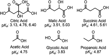
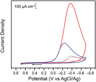
To probe the effect, if any, of the nature of the buffer on the electrochemical reduction of Cr(VI) on glassy carbon electrodes, two acids of similar structure to citric acid were chosen. Malic acid (pKa: 3.51 and 5.03) and succinic acid (pKa: 4.61 and 5.61) have the same backbone and carboxylic groups but differ by a hydroxyl functional group (Scheme 1).The two acids were used to prepare buffers at a pH of 4.75, following the data obtained for citrate buffers.21 Cyclic voltammograms were collected for the reduction of Cr(VI) in malate or succinate buffer solutions at pH 4.75 for two different concentrations of Cr(VI) (Fig. 1).
Differences are observed in both peak currents and peak potentials. At 0.20 mM, the peak faradaic current densities observed for Cr(VI) reduction are −99.3 μA cm−2 and −111 μA cm−2 in malate and succinate buffers respectively, with corresponding reduction peak potentials of −0.427 V and −0.371 V vs. Ag/AgCl. These differences in peak potentials are unexpected given the similarities in the two systems, including identical pH of the two buffers. At the higher concentration tested, after addition of 7.00 mM of potassium chromate, differences in the two buffers are even more pronounced, with reduction peak currents of −1139 μA cm−2 and −373 μA cm−2 for the malate and succinate buffers respectively, and corresponding reduction peak potentials of −0.370 V and −0.240 V vs. Ag/AgCl. This unexpected large discrepancy was investigated further. Cyclic voltammetry experiments were repeated at various scan rates (Fig. S1 and S2†), and the evolution of the log of the peak currents was plotted as a function of the log of the scan rate (Fig. 2).
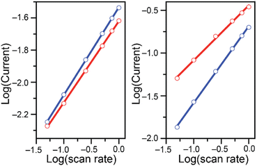 | ||
| Fig. 2 Log of the absolute values of the reduction peak currents (mA) plotted as a function of the log of the scan rate (V s−1) for cyclic voltammetry studies of 0.20 (left) and 7.00 mM (right) K2CrO4 added to 0.10 M malate (red) and succinate (blue) buffers at pH 4.75. Data in Fig. S1 and S2† Linear fit parameters summarized in Table 1. | ||
At the lower Cr(VI) concentration of 0.20 mM, the reduction peak currents vary linearly with the square-root of the scan rate in both buffers, as seen by the linear fit with a slope close to 0.5 (Fig. 2 and Table 1 entries 1 and 2). On the other hand, at the higher Cr(VI) concentration of 7.00 mM, a difference is observed between the two buffer systems (Fig. 2, right). In the malate buffer, the reduction peak currents still vary linearly with respect to the square-root of the scan rate (slope of ca. 0.5, Table 1 entry 7), whereas in the succinate buffer the reduction peak currents vary linearly with the scan rate (slope of ca. 1, Table 1 entry 8). This supports the notion that at low Cr(VI) concentration the reduction observed is diffusion-controlled in both buffers, while at higher Cr(VI) concentration the reduction is diffusion-controlled only in malate, and surface-controlled in the succinate buffer.30–32 This analysis shows that the choice of acid/base couple used for the supporting buffer plays a role in the reduction of Cr(VI).
| Entry | Buffer | K2CrO4 (mM) | Slopea | R2 |
|---|---|---|---|---|
| a Slope of the linear fits obtained for the log of the absolute values of the reduction peak currents (in mA) as a function of the log of scan rates (in V s−1). Full data provided in Fig. S9 through S14. | ||||
| 1 | Malate | 0.20 | 0.506 ± 0.004 | 0.999 |
| 2 | Succinate | 0.20 | 0.546 ± 0.002 | 0.999 |
| 3 | Citrate | 0.20 | 0.498 ± 0.009 | 0.999 |
| 4 | Acetate | 0.20 | 0.487 ± 0.011 | 0.998 |
| 5 | Propanoate | 0.20 | 0.514 ± 0.004 | 0.999 |
| 6 | Glycolate | 0.20 | 0.529 ± 0.002 | 0.966 |
| 7 | Malate | 7.00 | 0.643 ± 0.016 | 0.998 |
| 8 | Succinate | 7.00 | 0.897 ± 0.011 | 0.999 |
| 9 | Citrate | 7.00 | 0.763 ± 0.013 | 0.999 |
| 10 | Acetate | 7.00 | 0.893 ± 0.026 | 0.997 |
| 11 | Propanoate | 7.00 | 0.923 ± 0.009 | 0.999 |
| 12 | Glycolate | 7.00 | 0.448 ± 0.009 | 0.998 |
Effect of pH on reduction of 0.20 mM Cr(VI)
We previously reported that when reduction peak potentials for 0.20 mM Cr(VI) solutions in citric acid buffers were plotted as a function of pH, the reduction peak potentials shift by 59.3 mV per pH.21 This supports a mechanism in which the Cr(VI) reduction process is kinetically gated by a proton-coupled electron transfer (PCET) process. Similar trends were observed with the malate and succinate buffers studied here (Fig. 3): as the pH of the buffer was varied from 3.75 to 5.25, the observed reduction peak potential for the reduction of Cr(VI) shifted in both malate and succinate buffers (Fig. S3 and S4†). The peak shifts linearly as a function of pH in both buffers (Fig. 3), with slopes suggesting a similar mechanistic pathway in these conditions. Cr(VI) reduction peak potentials plotted as a function of pH values were observed to vary by 62.9 mV per pH when using a 0.10 M malate buffer, and by 62.4 mV per pH when using a 0.10 M succinate buffer in the pH range tested. The pH of the buffers in the rest of this study, pH 4.75, is well within this range which supports the hypothesis of a similar mechanistic slow step across the different buffers tested: a rate limiting proton-coupled electron transfer process. The half reaction at the electrode for this PCET process is thus expected to follow the overall reaction in Scheme 2: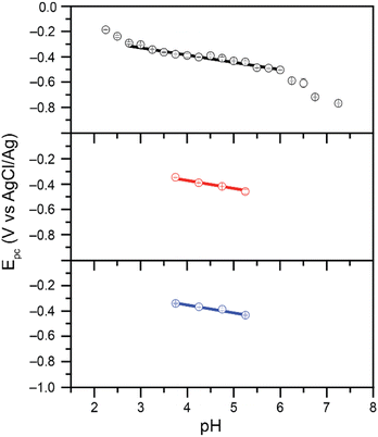 | ||
| Fig. 3 Reduction peak potential values plotted as a function of pH for 0.20 mM Cr(VI) added as K2CrO4 in 0.10 M citrate (black, top), malate (red, middle), and succinate (blue, bottom) buffers. Data collected in 1.00 M KCl electrolyte at scan rates of 0.10 V s−1. Citrate data from ref. 21. Slopes of 62.9 mV per pH (r2 = 0.984) and 62.4 mV per pH (r2 = 0.991) observed for malate and succinate respectively. | ||
 | ||
| Scheme 2 Proposed PCET process gating Cr(VI) reduction. Adapted from ref. 22. | ||
Different pathways could be followed by the PCET process in Scheme 2: a proton transfer followed by an electron transfer (PT-ET), an electron transfer followed by a proton transfer (ET-PT), or a concerted proton-electron transfer pathway (CPET).33 Distinguishing between these is beyond the scope of the current study. This overall rate limiting PCET step is expected to be followed by further rapid proton and electron transfers, which could happen at the electrode or through solution electron transfers. Current mechanistic proposals are that the rate limiting initial PCET is followed by disproportionation of two Cr(V) to yield a Cr(IV) and a Cr(VI).7,22 The Cr(IV) can then either react with another Cr(V) to yield a Cr(III) product and a Cr(VI), or two Cr(IV) could disproportionate instead to yield a Cr(III) and a Cr(V) which would further disproportionate.7,22 All these steps are proposed to be fast and would also involve the movement of protons. Probing the exact nature of these steps is not accessible in the experimental conditions as they are gated by the slow initial PCET process.
These results overall support the claim that at the lower Cr(VI) concentrations of 0.20 mM, the nature of the buffer does not appear to impact the type of mechanistic step involved in the reduction (PCET). This means reactivity observed should be transferable to a wide range of buffer systems. The differences observed in peak potentials, however, point to an effect of the buffer on the rate limiting PCET step gating the reduction process.
Effect of buffer concentration
Experiments were repeated at different buffer strengths. Two representative buffer systems were chosen (citrate and acetate) at concentrations ranging from 0.05 to 0.75 M. Overall, the buffer strength had very little effect on the data, with reduction peak currents and reduction peak potentials giving similar values for the reduction of 0.20 mM Cr(VI) (Fig. S5†). At the higher Cr(VI) concentration of 7.00 mM, the nature of the buffer seems to have more of an effect on the reduction as seen in Fig. 1. Further experiments were thus conducted at 7.00 mM of Cr(VI) using malate and succinate buffers at pH 4.75 while varying the buffer concentration. Both the reduction peak potentials and reduction peak currents (Fig. S6†) are affected by a change from malate to succinate buffers, but very little change is observed in a given buffer as the buffer concentration is varied (Fig. S6†). These data demonstrated that while the nature of the acid/base couple used as buffer has an impact on Cr(VI) reduction, the buffer strength has minimal effect on Cr(VI) reduction within the range tested. A standard buffer concentration of 0.10 M was used thereafter.Effect of supporting electrolyte
An electrolyte of KCl at 1.00 M was added as standard protocol in an effort to limit the potential impact of variations in ionic strength while the buffer or pH were changed. However, Cl− anions could act as inner sphere X-type ligand to Cr(III) products, which could explain the observation of some electrode adsorbed species in certain conditions. To confirm the minimal impact of the presence of Cl− anions on Cr(VI) reduction, CVs were collected in the presence of KNO3 instead of KCl, as well as without any added electrolyte (the buffer is sufficient to act as the electrolyte for conductivity purposes). Negative impacts from the presence of Cl− anions on the solubility of possible Cr(III) products would be expected to lead to a decrease of the observed peak currents in the presence of Cl−. The obtained data, summarized in Fig. S7 through S8,† confirm the minor role played by the presence of Cl− anions in the electrochemical cell.Effect of acid structure on Cr(VI) reduction
The differences observed by cyclic voltammetry for Cr(VI) reduction at pH 4.75 in malate and succinate buffers point to an impact of the nature of the buffer on the reduction, which becomes more pronounced at higher Cr(VI) concentrations. The structure of these two acids differ by a hydroxyl group. Other pairs of buffers were tested to further probe the impact of the structure of the buffer (Scheme 1). Cyclic voltammograms were collected at various scan rates in each buffer system in the same conditions used previously. To determine if Cr(VI) reduction in each buffer is diffusion or surface-controlled, the reduction peak currents were collected and the log of peak current was plotted as a function of log of the scan rate (Fig. S9 through S14†). The results are summarized in Table 1.Similar to what was observed in malate and succinate buffers, a slope close to 0.5 was obtained in every buffer at 0.20 mM Cr(VI) concentration, indicating a linear relationship between the current and the square root of scan rate. This is expected for a diffusion-controlled process. The nature of the buffer had a minimal impact on the observed diffusion-controlled reduction behavior in these conditions, although the magnitude of peak currents varied across the buffer system used. In contrast, at higher concentrations of Cr(VI), the obtained slopes are closer to unity for most buffers, which indicates a direct linear relationship between the peak current and scan rate. This is what is expected of a system in which the reduction event involves surface adsorbed species.30–32 The exceptions are malate and glycolate buffers in which Cr(VI) reduction remains closer to diffusion-controlled on the time scale of the cyclic voltammetry scans (Table 1 entries 7 and 12). Citrate appears to exist in an intermediate range (Table 1 entry 9). This demonstrates a level of acid specificity. The changes in the structure of the acid/base couples used can be viewed through the lens of: (i) the presence of an added hydroxyl group (malate vs. succinate and acetate vs. glycolate), (ii) the chelating ability of the base (e.g. succinate vs. propanoate), and (iii) the pKa compared to the pH of the experiment. While hydroxyl groups are present in both malate and glycolate buffers, their presence alone does not explain the observed data as citrate also possesses a hydroxyl group. The differences observed simply between the data collected with malate and succinate buffers suggest that chelating ability of the base alone does not fully explain the observed Cr(VI) reduction behavior either. The change of pKa alone also doesn't fully explain the data. Glycolic acid has a lower pKa than acetic and propanoic acids, which would suggest a greater presence of the base in the pH 4.75 buffer. This could explain better interactions with the possible Cr3+ product, preventing adsorption by keeping the Cr3+ solubilized. However, similar reasoning would suggest citric acid should promote diffusion-controlled reduction more than malic acid, which is not what is observed experimentally (Table 1, entry 7 vs. 9). Overall, the impact of small organic acid and bases is more complex, varying likely with a combination of these factors. The presence of any effect of the buffer on the electrochemical signal observed was counter intuitive given that hydronium, H3O+, is the expected common proton carrier across these buffers following the Brønsted–Lowry definition.25 Experimental evidence supports a more complex situation, in which the acid as the proton carrier or the base as a chelator may impact the PCET process at the electrode. This highlights the intricate water chemistry of chromium, and opens the way to further studies on the impact of specific acid/base small molecules present in drinking and water streams on Cr(VI) reduction.
Products and electrode recyclability
The change in behavior observed as a function of buffer type and Cr(VI) concentration suggests that depending on conditions both soluble and insoluble products are formed at the electrode surface upon reduction of Cr(VI) in cyclic voltammetry conditions. In an effort to identify the oxidation state of chromium in the products, controlled potential electrolysis experiments were performed in a 2-compartment bulk electrolysis cell. A fixed potential was applied to the working electrode and the current response was measured as a function of time. The experiments were done in 0.10 M malate and succinate buffers at pH 4.75, with applied potentials of −0.300 V vs. Ag/AgCl for 0.20 mM Cr(VI) and −0.200 V vs. Ag/AgCl for 7.00 mM Cr(VI). The applied potentials were chosen based on the reduction peak potentials observed in cyclic voltammetry data. As expected, the glassy carbon electrodes foul during Cr(VI) reduction on the timescale of bulk electrolysis experiments (Fig. 4).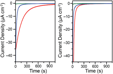 | ||
| Fig. 4 Chronoamperometry traces for the reduction of 0.20 mM K2CrO4 at −0.300 V vs. Ag/AgCl (left) and 7.00 mM K2CrO4 at −0.200 V vs. Ag/AgCl (right). Data collected in 0.10 M malate (red) or succinate (blue) buffers at pH 4.75 in water with a 1.00 M KCl electrolyte while stirring. Green traces are backgrounds in the malate buffer at the same potential in the absence of Cr(VI). For charge passed and backgrounds in the succinate buffer see Fig. S15 through S18.† Data collected on a 5 mm diameter glassy carbon electrode. | ||
Although in low Cr(VI) concentrations the reactions are diffusion-controlled on the time scale of a cyclic voltammetry scan, over the time scale of the chronoamperometry species clearly deposit on the electrode surface. This is apparent from the steep drop in current observed over time. After only 3 minutes the reduction current is 36% what it was at 5 seconds in the malate buffer and only 3% in the succinate buffer when starting with 0.20 mM Cr(VI). While current is expected to decrease over time as the concentration of Cr(VI) diminishes in the bulk solution, the activity changes are much steeper than can be accounted for by the change in Cr(VI) concentration alone. The electrodes foul over time, likely through the deposition of an insulating layer. The complete fouling of the electrode occurs at different times depending on the buffer system used and the Cr(VI) concentration. In a malate buffer at low Cr(VI) concentrations, Cr(VI) reduction activity is very diminished but still present after 25 minutes (Fig. S15†). In contrast, the electrode surface was fully fouled after only 15 min when using a succinate buffer (Fig. S16†). Similar trends are observed at the higher Cr(VI) concentration tested, only more pronounced (Fig. S17 and S18†). The total charge passed is summarized in Table 2, along with the corresponding theoretical decrease of Cr(VI) concentration expected in the bulk. Given the starting Cr(VI) concentration in the bulk electrolysis cell, as well as the volume of the solution, and assuming an overall 3 electron reduction process, the theoretical total charge passed to fully reduce all Cr(VI) can be calculated using:
| Q = nNF | (3) |
![[thin space (1/6-em)]](https://www.rsc.org/images/entities/char_2009.gif) 485 C mol−1. This corresponds to 0.579 mC for 0.20 mM Cr(VI) and 20.26 mC for 7.00 mM Cr(VI). The actual charge passed in the bulk electrolysis experiments to foul the electrode surface (Table 2) did not exceed 1.5 mC, for a maximum theoretical Cr(VI) reduction yield of 2.58%.
485 C mol−1. This corresponds to 0.579 mC for 0.20 mM Cr(VI) and 20.26 mC for 7.00 mM Cr(VI). The actual charge passed in the bulk electrolysis experiments to foul the electrode surface (Table 2) did not exceed 1.5 mC, for a maximum theoretical Cr(VI) reduction yield of 2.58%.
| Entry | Buffer | K2CrO4 (mM) | Charge passedd (mC) | Conversione |
|---|---|---|---|---|
| a Data collected on a 5 mm diameter glassy carbon working electrode in 0.10 M buffers at pH 4.75 in water with a 1.00 M KCl electrolyte while stirring. Full data in Fig. S15 through S18.b Applied potential of −0.300 V vs. Ag/AgCl.c Applied potential of −0.200 V vs. Ag/AgCl.d Charge after 30 min, corrected from background contributions.e Maximum conversion of Cr(VI) after 30 min, assuming a 3-electron reduction. | ||||
| 1b | Malate | 0.20 | 1.493 | 2.58% |
| 2b | Succinate | 0.20 | 0.249 | 1.43% |
| 3c | Malate | 7.00 | 1.022 | 1.77% |
| 4c | Succinate | 7.00 | 0.315 | 0.54% |
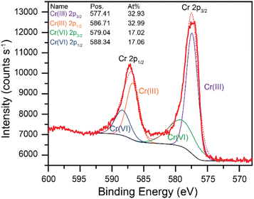
Throughout these studies, the Cr(VI) reduction products were assumed to be in the Cr(III) oxidation state. XPS data were collected to confirm the formation of Cr(III) species during the Cr(VI) reduction process. A high purity vitreous carbon planchet was used as the working electrode in a bulk electrolysis cell (see experimental section for details). A fixed potential of −0.200 V vs. Ag/AgCl was applied to a solution of 7.00 mM Cr(VI) in 0.10 M succinate buffer at pH 4.75 until the electrode was fully fouled. The electrode was then removed from the solution and immediately dried under vacuum for XPS analysis. The resulting high-resolution core level Cr 2p signals are shown in Fig. 5 (wide region survey scan provided in Fig. S19†). The red traces in Fig. 5 are the experimental data (bold) and the modeled data (dashed). The model includes contributions from both Cr(III) and Cr(VI). Cr(III) is the major species on the electrode surface, accounting for over 2/3 of the intensity. These data confirm that Cr(VI) is reduced to Cr(III) at the electrode surface in these conditions.
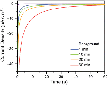
While Cr(VI) reduction to Cr(III) was confirmed, the rate at which the electrodes foul poses a significant challenge. To increase the amount of Cr(VI) reduced on the electrodes without re-polishing, recycling experiments were performed. Based on the reported Pourbaix diagram for chromium at 10−6 M total dissolved chromium,7,9 soluble Cr(III) species are expected to be generated in more acidic conditions, while insoluble oxides are expected in more basic conditions. Attempts at recycling the fouled glassy carbon electrodes thus consisted in soaking the fouled electrodes in 0.50 M H2SO4, to solubilize the Cr(III) products, followed by a wash in H2O and immediate re-use in the bulk electrolysis cell for Cr(VI) reduction without re-polishing the electrode. Some activity is regained after as little as 1 minute in 0.5 M H2SO4. As the fouled electrodes are soaked in acid for longer periods of time, activity towards Cr(VI) reduction is regained. This is demonstrated in Fig. 6 using a 7.00 mM Cr(VI) solution in malate buffer.
This successful electrode recycling effect is also observed in the succinate buffer. Soaking the fouled electrode for 60 minutes in 0.50 M H2SO4 regenerated most of the Cr(VI) reduction activity initially observed on the pristine polished glassy carbon electrode (Fig. S20†). This demonstrates that electrodes can be easily recycled and regain Cr(VI) reduction activity without the need for re-polishing. The process may be optimized further with variations of acids or pH used in the rinsing solution, although such practical device building considerations are outside the scope of the current study.
Conclusions
For successful electrochemical reduction of Cr(VI) in water, methods are required which are energy efficient, cost effective, and successful. Herein we demonstrate that Cr(III) is indeed formed during the electrochemical reduction of Cr(VI) in water on glassy carbon electrodes. The reduction proceeds in mildly acidic pH conditions, compared to the highly acidic conditions required previously.7,22,34–37 Crucially, the reduction proceeds on cheap glassy carbon electrodes compared to metals previously used.7 What is more, the use of glassy carbon as the electrode coupled to less acidic solution pH values shuts down the hydrogen evolution reaction. This is significant as it typically competes and plagues current methods. The electrochemical reduction of Cr(VI) is gated by a PCET step in the conditions tested. The major drawback to the system, as is the case for other current approaches, is the deposition of chromium-containing species on the electrode surface. In this work, we have first demonstrated that the nature of the chemical structure of the buffer impacts this process. Buffers made from acid/base couples which are able to promote chelation of transition metal cations lead to diffusion-controlled Cr(VI) reduction on the time scale of cyclic voltammetry experiments. It is hypothesized that chelation of the generated Cr(III) products is the main cause of this effect. In contrast, other buffers promoted surface adsorption, especially at higher Cr(VI) concentrations. These findings are of importance in the context of water purification, as it suggests the presence of small organic acids and bases in drinking and wastewater streams would impact electrochemical Cr(VI) reduction. In bulk electrolysis conditions, electrodes eventually fouled in all buffers, though more Cr(VI) reduction occurred before complete fouling in buffers observed to promote diffusion-controlled Cr(VI) reduction on the timescale of cyclic voltammetry experiments. It was demonstrated that activity of the electrodes can be restored after a simple acid wash step, without the need to re-polish the surface of the electrodes. Future work will be required to fully probe the chemistry of Cr(VI) and Cr(III) in water to develop methods which reduce or by-pass electrode fouling.Conflicts of interest
There are no conflicts to declare.Acknowledgements
The authors acknowledge support from the Louisiana Board of Regents Research Competitiveness Subprogram under contract number LEQSF(2019-22)-RD-A-05. This work was also supported through start-up funds from the Department of Chemistry and the College of Science at Louisiana State University, in part through the Office of Research & Economic Development and the Workforce and Innovation for a Stronger Economy (WISE)/Act 803 fund for equipment. CMS acknowledges partial support from the Louisiana Board of Regents for a Graduate Fellowship under the award number LEQSF(2014-19)-GF-02 as well as the Jerry D. Dumas Sr. and Nancy L. Dumas Superior Graduate Scholarship.Notes and references
- Y. B. Yin, S. Guo, K. N. Heck, C. A. Clark, C. L. Conrad, M. S. Wong, C. L. Coonrod and M. S. Wong, ACS Sustainable Chem. Eng., 2018, 6, 11160–11175 CrossRef CAS.
- A. J. Howarth, Y. Liu, J. T. Hupp and O. K. Farha, CrystEngComm, 2015, 17, 7245–7253 RSC.
- D. Tilman, J. Fargione, B. Wolff, C. D'Antonio, A. Dobson, R. Howarth, D. Schindler, W. H. Schlesinger, D. Simberloff and D. Swackhamer, Science, 2001, 292, 281–284 CrossRef CAS PubMed.
- S. Joyce, Environ. Health Perspect., 2000, 108(3), A120–A125 CrossRef CAS PubMed.
- R. J. Diaz and R. Rosenberg, Science, 2008, 321, 926–929 CrossRef CAS PubMed.
- C. D. Palmer and P. R. Wittbrodt, Environ. Health Perspect., 1991, 92, 25–40 CrossRef CAS PubMed.
- C. M. Stern, T. O. Jegede, V. A. Hulse and N. Elgrishi, Chem. Soc. Rev., 2021, 50, 1642–1667 RSC.
- M. Chebeir, G. Chen and H. Liu, Environ. Sci.: Water Res. Technol., 2016, 2, 906–914 RSC.
- B. Beverskog and I. Puigdomenech, Corros. Sci., 1997, 39, 43–57 CrossRef CAS.
- C. Viti, E. Marchi, F. Decorosi and L. Giovannetti, FEMS Microbiol. Rev., 2014, 38, 633–659 CrossRef CAS PubMed.
- R. Saha, R. Nandi and B. Saha, J. Coord. Chem., 2011, 64, 1782–1806 CrossRef CAS.
- S. Kalidhasan, A. Santhana Krishna Kumar, V. Rajesh and N. Rajesh, Coord. Chem. Rev., 2016, 317, 157–166 CrossRef CAS.
- C. E. Barrera-Díaz, V. Lugo-Lugo and B. Bilyeu, J. Hazard. Mater., 2012, 223–224, 1–12 CrossRef PubMed.
- H. A. Maitlo, K.-H. Kim, V. Kumar, S. Kim and J.-W. Park, Environ. Int., 2019, 130, 104748 CrossRef CAS PubMed.
- L. A. Malik, A. Bashir, A. Qureashi and A. H. Pandith, Environ. Chem. Lett., 2019, 17, 1495–1521 CrossRef CAS.
- C.-H. Weng, Y.-T. Lin, T. Y. Lin and C. M. Kao, J. Hazard. Mater., 2007, 149, 292–302 CrossRef CAS PubMed.
- F. Brito, J. Ascanio, S. Mateo, C. Hernández, L. Araujo, P. Gili, P. Martín-Zarza, S. Domínguez and A. Mederos, Polyhedron, 1997, 16, 3835–3846 CrossRef CAS.
- M. Pourbaix, Atlas of electrochemical equilibria in aqueous solutions, Pergamon Press, Oxford, 1967 Search PubMed.
- W. Jin, H. Du, S. Zheng and Y. Zhang, Electrochim. Acta, 2016, 191, 1044–1055 CrossRef CAS.
- Y. Zhao, Int. J. Electrochem. Sci., 2018, 13, 1250–1259 CrossRef CAS.
- C. M. Stern, D. W. Hayes, L. O. Kgoadi and N. Elgrishi, Environ. Sci.: Water Res. Technol., 2020, 6, 1256–1261 RSC.
- C. M. Welch, O. Nekrassova and R. G. Compton, Talanta, 2005, 65, 74–80 CAS.
- N. Elgrishi, D. A. Kurtz and J. L. Dempsey, J. Am. Chem. Soc., 2017, 139, 239–244 CrossRef CAS PubMed.
- D. A. Kurtz, D. Dhar, N. Elgrishi, B. Kandemir, S. F. McWilliams, W. C. Howland, C.-H. Chen and J. L. Dempsey, J. Am. Chem. Soc., 2021, 143, 3393–3406 CrossRef CAS PubMed.
- A. Kütt, S. Tshepelevitsh, J. Saame, M. Lõkov, I. Kaljurand, S. Selberg and I. Leito, European J. Org. Chem., 2021, 2021, 1407–1419 CrossRef.
- J. L. Alvarez-Hernandez, A. E. Sopchak and K. L. Bren, Inorg. Chem., 2020, 59, 8061–8069 CrossRef CAS PubMed.
- J. M. Le, G. Alachouzos, M. Chino, A. J. Frontier, A. Lombardi and K. L. Bren, Biochemistry, 2020, 59, 1289–1297 CrossRef CAS PubMed.
- C. R. Schneider, L. C. Lewis and H. S. Shafaat, Dalton Trans., 2019, 48, 15810–15821 RSC.
- I. Márquez, J. L. Olloqui-Sariego, M. Molero, R. Andreu, E. Roldán and J. J. Calvente, Inorg. Chem., 2021, 60, 42–54 CrossRef PubMed.
- N. Elgrishi, K. J. Rountree, B. D. McCarthy, E. S. Rountree, T. T. Eisenhart and J. L. Dempsey, J. Chem. Educ., 2018, 95, 197–206 CrossRef CAS.
- C. G. Zoski, Handbook of Electrochemistry, Elsevier, Oxford, 2007 Search PubMed.
- A. J. Bard and L. R. Faulkner, Electrochemical Methods: Fundamentals and Applications, John Wiley & Sons, Inc., Hoboken, NJ, 2nd edn, 2001 Search PubMed.
- N. Elgrishi, B. D. McCarthy, E. S. Rountree and J. L. Dempsey, ACS Catal., 2016, 6, 3644–3659 CrossRef CAS.
- W. Jin, G. Wu and A. Chen, Analyst, 2014, 139, 235–241 RSC.
- B. K. Jena and C. R. Raj, Talanta, 2008, 76, 161–165 CrossRef CAS PubMed.
- R. Buják and K. Varga, Electrochim. Acta, 2006, 52, 332–341 CrossRef.
- A. F. Diaz and D. Schermer, J. Electrochem. Soc., 1985, 132, 2571 CrossRef CAS.
Footnote |
| † Electronic supplementary information (ESI) available: Electrochemical data and analyses, XPS data, as referenced in the text. See DOI: https://doi.org/10.1039/d2ra05943f |
| This journal is © The Royal Society of Chemistry 2022 |

