DOI:
10.1039/D2RA05646A
(Paper)
RSC Adv., 2022,
12, 35064-35071
Enhanced photocatalytic activity of a flower-like In2O3/ZnGa2O4:Cr heterojunction composite with long persisting luminescence†‡
Received
7th September 2022
, Accepted 21st November 2022
First published on 7th December 2022
Abstract
The development of new photocatalysts with high photocatalytic efficiency and catalytic stability, and long persisting luminescence is critical for ensuring environmental protection and clean energy production. In this study, we develop a flower-like In2O3/ZnGa2O4:Cr heterojunction composite with enhanced ultraviolet (UV) photocatalytic activity using a facile two-step hydrothermal method. The spectral response range of the heterojunction composite is widened to the visible-light range owing to the presence of the ZnGa2O4:Cr persistent luminescence nanoparticles with sizes of less than 10 nm. The heterojunction composite is dispersed on the flower petals of In2O3. The In2O3/ZnGa2O4:Cr/1:1 composite exhibits photo-degradation performance for rhodamine B degradation that is superior to those of pure In2O3, ZnGa2O4:Cr, In2O3/ZnGa2O4:Cr/1:0.5 and In2O3/ZnGa2O4:Cr/1:2, achieving complete degradation after 80 min under UV light irradiation. Moreover, it exhibits long afterglow luminescence that lasts for more than 72 h. Thus, the In2O3/ZnGa2O4:Cr/1:1 composite shows great potential for use in round-the-clock photocatalytic applications.
1. Introduction
With rapid economic development, humans have focused their attention on production of colored materials worldwide. This has led to an ongoing increase in the annual output of synthetic dyes. Due to the synthetic dye content in the large amounts of wastewater discharged by dye industries during the production process and the absence of effective treatment, the discharge water harms the environment.1–3 Photocatalysis technology based on solar energy is a promising approach for the treatment of environmental pollution and for green renewable energy utilization. This technology uses semiconductor photocatalysts that have been investigated in the past several decades. These photocatalysts include TiO2, CeO2, g-C3N4, ZnO, ZnS, WO3, In2O3, and Bi2WO6.4–11 Among these photocatalysts, as a typical n-type semiconductor photo-catalyst with a band gap of 2.8 eV and outstanding thermodynamic stability,12 In2O3 has drawn significant attention in the studies related to photo-electrochemistry, chemical sensors, photocatalytic hydrogen generation, and the degradation of organic pollutants.13–16 However, pure In2O3 still shows limited photocatalytic activity owing to the fast recombination of the photo-generated electrons and holes and the low utilization of the solar spectrum.17 Therefore, the construction of heterojunction composites is an effective method to substantially enhance the photocatalytic performance of In2O3. For example, heterojunction composites such as In2O3/BiVO4, p-CuO–n-In2O3, and ZnFe2O4/In2O3 have been rationally designed and exhibit enhanced photocatalytic activity.18–20 ZnGa2O4 is an important p-type semiconductor material. It is a blue-emitting phosphor with a wide band gap and a d10 electron configuration.21 ZnGa2O4 shows great potential for applications in various areas, such as gas sensors, ultraviolet (UV) photodetection, solar energy conversion, and UV light photocatalysis.22–26 It is an ideal host lattice that can emit near-infrared (NIR) afterglow upon chromium ion (Cr3+) doping. Therefore, Cr3+-doped ZnGa2O4 exhibits great potential for in vivo bio-imaging with a high signal-to-background ratio.27 Our previous work showed that the Bi3+ and Cr3+ co-doped ZnGa2O4 exhibit excellent photocatalytic activity and NIR persistent luminescence owing to an increase in the trap density and a decrease in the band gap that prolong the lifetime of the photo-generated electron–hole pairs and increase visible light absorption.24
Zhang et al. were the first to achieve an afterglow degradation effect for rhodamine B (RhB) by using a separated long-lasting phosphors layer to excite TiO2.28 Many researchers have sought to attain high-efficiency LLP-assisted photocatalyst is using materials such as CaAl2O4:(Eu,Nd)/TiO2−xNy,29 SrAl2O4:Eu2+,Dy3+/g-C3N4@NH2-UiO-66,30 TiO2/Sr4Al14O25:Eu2+,Dy3+,31 Ca12Al14O33:Tb3+(Sm3+),32 (ZnO:Ga2O3:2GeO2):Cr3+/TiO2 and Zn2SiO4:Ga3+.33,34 However the photocatalytic properties of these materials still need to be improved. We expect that the combination of In2O3 and ZnGa2O4:Cr3+ will prolong carrier lifetimes and improve the band gap of the In2O3/ZnGa2O4:Cr heterojunction composite and also will realize a round-the-clock photocatalytic reaction with long persistent luminescence. To the best of our knowledge, no In2O3/ZnGa2O4:Cr-based composites have been reported to date.
Herein, we developed a flower-like In2O3/ZnGa2O4:Cr heterojunction composite with enhanced UV-light photocatalytic activity using a facile two-step hydrothermal method. The spectral response range of the heterojunction composite is widened to the visible light range by the ZnGa2O4:Cr persistent luminescence nanoparticles (PLNPs) with sizes smaller than 10 nm. The heterojunction composite was dispersed on the flower petals of In2O3. The In2O3/ZnGa2O4:Cr composite exhibited high photo-degradation efficiency for RhB degradation that was higher than those of pure In2O3 and ZnGa2O4:Cr, with complete degradation achieved after 80 min under UV light irradiation. Moreover, the In2O3/ZnGa2O4:Cr composite showed long afterglow luminescence that lasted for more than 72 h. Thus, it shows great potential for round-the-clock photocatalytic applications.
2. Experimental
2.1 Materials and reagents
All of the reagents were used as received without further purification. Ga2O3 (99.99%), InCl3·4H2O (99.9%), Zn(NO3)2·6H2O (99.99%), C2H6O2, Cr(NO3)3·9H2O (99.95%), and C12H25NaSO4 were purchased from Aladdin (Shanghai, China). CH4N2O, concentrated HNO3, and aqueous NH3 (15 wt%) were purchased from Shanghai Chemical Reagent (Shanghai, China). Ultrapure water (ULPHW) was used to prepare all of the solutions and was also used in the photocatalytic tests.
2.2 Preparation of the In2O3/ZnGa2O4:Cr composite
The In2O3/ZnGa2O4:Cr composites were prepared using a two-step hydrothermal method (Fig. 1). First, flower-like In2O3 microspheres were synthesized.28 Then, InCl3·4H2O (0.391 g), C12H25NaO4S (1.09 g), and CH4N2O (0.4 g) were dissolved in ULPHW (80 mL). Then, the mixture solution was transferred to a Teflon-lined stainless steel autoclave and heated at 120 °C for 12 h. The resulting colloid solution was centrifuged, and white precipitates were obtained. The precipitates were washed with distilled water and ethanol several times and dried in the air. Finally, the dried precipitates were annealed in air at 500 °C for 2 h, and flower-like In2O3 microspheres were obtained.
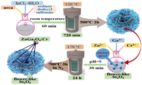 |
| | Fig. 1 Schematic of the preparation of the In2O3/ZnGa2O4:Cr composites. | |
Subsequently, In2O3 (100 mg) was dispersed in C2H6O2 (10 mL) for 30 min. The mixed solution was stirred at room temperature for 30 min. Then, Ga3+ (0.2 mol L−1, 1.99 mL), Zn2+ (0.4 mol L−1, 1 mL), and Cr3+ (0.01 mol L−1, 0.4 mL) solutions were added to the above mixed solution, and stirred for 30 min. Aqueous NH3 was added to the mixture to adjust the pH to 9. The resulting mixture was transferred to an autoclave and heated at 170 °C for 24 h. The products were centrifuged. Finally, the sample was annealed at 700 °C in N2 protection for 3 h. The obtained sample was denoted as the In2O3/ZnGa2O4:Cr/1:1 composite.
2.3 Sample characterization
The X-ray diffraction (XRD) patterns for the obtained samples were recorded using a Bruker D8 Focus Advance X-ray diffractometer (Bruker, Germany) with Cu-Kα radiation (λ = 0.15406 nm). The microstructures and chemical composition were determined using a SU8220 field-emission scanning electron microscope with an EDS spectrometer (Hitachi, Japan). High-resolution transmission electron microscope (HR-TEM) images were obtained using a JEM-2100 HR-TEM microscope (JEOL, Japan). Photoluminescence spectra and persistent luminescence decay curves were obtained using an F-4500 fluorescence spectrophotometer (Hitachi, Japan). Ultraviolet-visible (UV-vis) diffuse reflectance spectra were recorded using a UV-vis spectrophotometer (Shimadzu UV-2600, Japan).
2.4 Photocatalytic activity test
We evaluated the photocatalytic performance of the as-prepared In2O3/ZnGa2O4:Cr composites by measuring the photo-degradation efficiency of RhB under UV irradiation by a mercury lamp (300 W, illumination intensity is 8.1346 W cm−2) at room temperature. An In2O3/ZnGa2O4:Cr sample (20 mg) was combined with a 10 mg L−1 aqueous RhB solution (40 mL). Magnetic stirring was performed continuously in the dark for 40 min to reach the adsorption–desorption equilibrium. Then, the suspension was placed under UV light irradiation, and the samples were collected, separated, and analyzed with a spectrophotometer at regular time intervals (every 20 min) using the same method.
3. Results and discussion
3.1 Characterization of the crystal structure
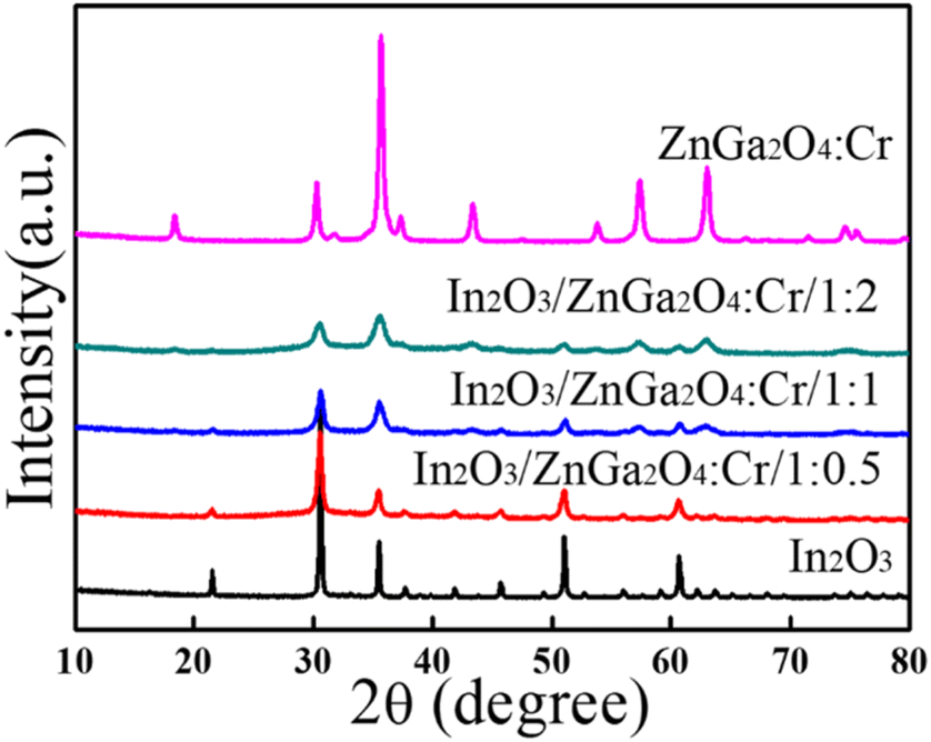
The crystal structures of the as-prepared flower-like In2O3, ZnGa2O4:Cr, and In2O3/ZnGa2O4:Cr composites were characterized using XRD. Fig. 2 shows that all of the peaks were assigned to the In2O3 sample with the peaks at the 2θ values of 21.47°, 30.59°, 35.47°, 37.58°, 41.49°, 45.64°, 51.06°, 56.08°, and 60.71° indexed to the (211), (222), (400), (411), (332), (431), (440), (611), and (622) cubic In2O3 crystal planes, respectively,35 that are consistent with the standard JCPDS pattern (file no.06-0416). Moreover, no impurity diffraction peaks were observed. In the ZnGa2O4:Cr sample, the peaks were observed at the 2θ of 18.45°, 30.28°, 35.7°, 37.4°, 43.58°, 53.85°, 57.56°, 63.19°, and 74.72°, and all of the diffraction peaks were consistent with the spinel phase of ZnGa2O4 (file no. 38-1240) and could be indexed as the (111), (220), (311), (222), (400), (422), (511), (440), and (531) crystal planes, respectively.27 Furthermore, the diffraction peaks of the In2O3/ZnGa2O4:Cr/1:1 heterostructure were similar to the corresponding XRD patterns of cubic In2O3 and the spinel phase of ZnGa2O4. Moreover, with increasing ZnGa2O4:Cr content, the diffraction peaks of ZnGa2O4:Cr gradually became stronger than those of In2O3. These results revealed that the cubic and spinel phases coexisted, indicating that In2O3/ZnGa2O4:Cr/1:1 heterostructure composites were successfully constructed with ZnGa2O4:Cr PLNPs with sizes of less than 10 nm dispersed on the flower petals of In2O3. Fig. S1‡ shows the diffraction peaks for the samples with the different contents of In2O3 and ZnGa2O4:Cr. No impurity phases were observed.
 |
| | Fig. 2 XRD patterns of the In2O3, ZnGa2O4:Cr, and In2O3/ZnGa2O4:Cr composites. | |
3.2 Morphology analysis
The morphology and elemental composition of the flower-like In2O3, ZnGa2O4:Cr, and In2O3/ZnGa2O4:Cr/1:1 composites were further investigated using FESEM, TEM, and EDS. The low-magnification FESEM image of In2O3 (Fig. 3a) shows that the products consisted of numerous flower-like microspheres with sizes ranging from 2 to 5 μm. Detailed morphology information of In2O3 was obtained via enlarged magnification FESEM (Fig. 3b) and TEM (Fig. 3c), revealing that these flower-like nanostructures are formed from nanosheets. Notably, the thickness of the flower petals and the edge of the nanosheets is approximately 20 nm, and the as-obtained flower-like structure can generally be classified as a hierarchical structure. The FESEM and TEM images (Fig. 3d and e) of the In2O3/ZnGa2O4:Cr/1:1 composite show that the flower-like structure was preserved. The dark spots observed in the images had a diameter of approximately 10 nm and represented ZnGa2O4:Cr PLNPs that were well-dispersed on the flower petals of In2O3. The HR-TEM and SAED analyses indicated that the ZnGa2O4:Cr PLNPs had a single-crystal structure and that the distance between the lattice fringes was 0.48 nm (Fig. 3f). This distance corresponds to the d-spacing of the ZnGa2O4(111) lattice planes. Furthermore, the SAED pattern confirmed that the crystals of the ZnGa2O4:Cr PLNPs were pure spinel crystals. The results of the EDS analysis demonstrated that the flower-like In2O3 was composed of only In and O2 (Fig. 3g) and that the In2O3/ZnGa2O4:Cr/1:1 composite was composed of only In, Ga, Zn, Cr, and O2 (Fig. 3h). Moreover, no other elements were found. Using EDS-mapping images, we further confirmed that the In, Ga, O, Zn, and Cr elements were uniformly distributed over the In2O3/ZnGa2O4:Cr composites (Fig. S2‡). These results indicated that the ZnGa2O4:Cr PLNPs were successfully embedded in the flower petals of In2O3 and that the In2O3/ZnGa2O4:Cr/1:1 heterojunction composite was successfully constructed.
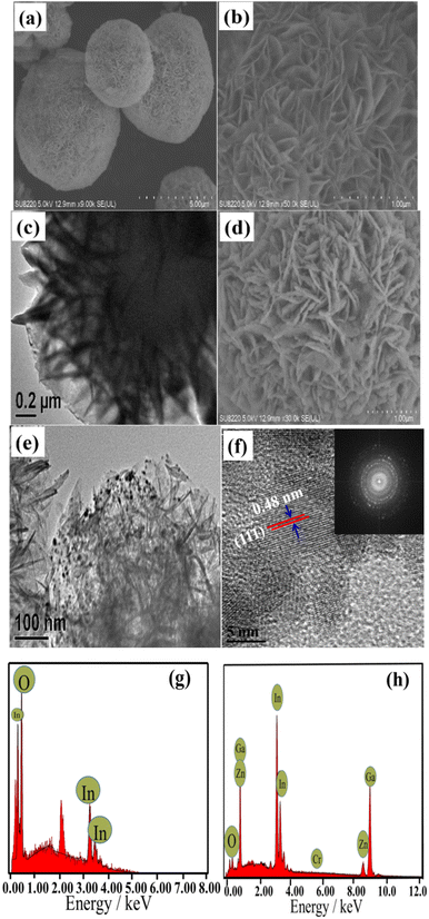 |
| | Fig. 3 (a–c) SEM and TEM images of flower-like In2O3; (d–f)SEM and TEM, HRTEM, and SAED images of the In2O3/ZnGa2O4:Cr/1:1 composites; EDS patterns of the (g) flower-like In2O3 and (h) In2O3/ZnGa2O4:Cr/1:1 composites. | |
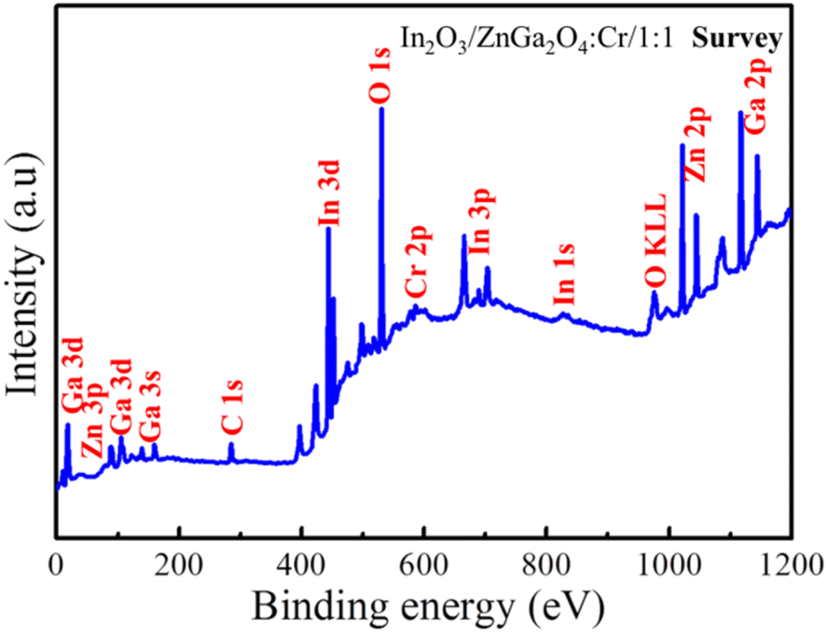
To measure the surface chemical composition and the chemical states of the elements, the In2O3/ZnGa2O4:Cr/1:1 composite was characterized by XPS. Peaks of the In, Ga, O, Zn, and Cr and C elements can be observed from the XPS survey spectrum of the In2O3/ZnGa2O4:Cr/1:1 composite (Fig. 4), which is consistent with the EDS analysis results. The peak for C 1s at 284.8 eV is attributed to adventitious hydrocarbon from the XPS instrument.36 The corresponding high-resolution spectra are also shown in Fig. S3(a and b).‡ The Zn 2p spectrum had two peaks at 1022.28 eV and 1045.35 eV assigned to Zn 2p3/2 and Zn 2p1/2, respectively, while the Ga 2p spectrum consisted of the peaks centered at the binding energies of 1118.34 eV and 1145.25 eV that were assigned to Ga 2p3/2 and Ga 2p1/2, respectively. These observations demonstrate that Zn and Ga are present in the +2 and +3 oxidization states, respectively. Moreover, the O 1s core level spectrum of the In2O3/ZnGa2O4:Cr composites are shown in Fig. S3c,‡ and the major peaks centered at 529.83, 530.23, and 531.85 eV are attributed to lattice oxygen in the In–O, Zn–O, and Ga–O of In2O3/ZnGa2O4:Cr composites, respectively, whereas the weak peak at 532.17 eV is due to the presence of the surface adsorbed hydroxyl oxygen species.37–39 The In 3d spectrum also reveals two symmetrical peaks a 444.78 eV (In 3d5/2) and 452.39 eV (In 3d3/2) (Fig. S3d‡) that are positively shifted compared to the peaks in pure In2O3 (444.3 eV, 451.8 eV), clearly indicating the presence of strong interactions between In2O3 and ZnGa2O4:Cr. This strong electronic interaction is essential for the transfer of the photo-generated charge carriers and the improvement of the photo-reactivity.40,41
 |
| | Fig. 4 Survey XPS spectra of the In2O3/ZnGa2O4:Cr/1:1 composites. | |
3.3 Optical properties and band structure
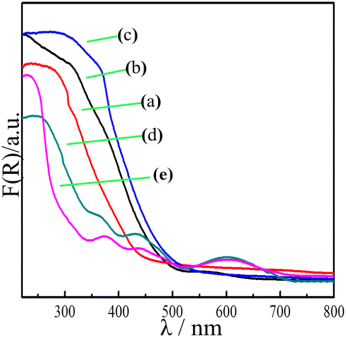
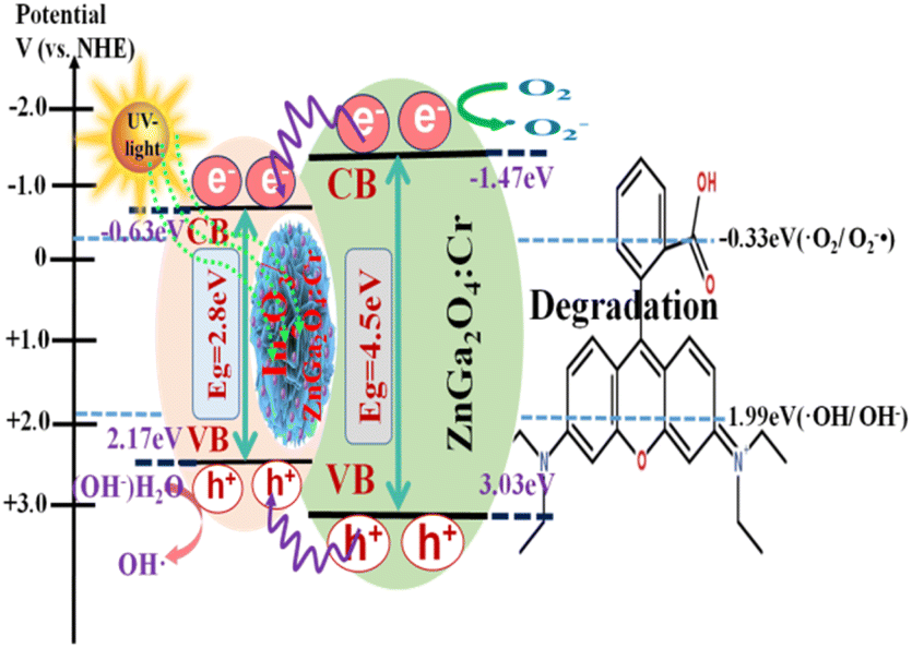
The optical absorption of the samples was measured by UV-vis diffuse reflectance spectroscopy (DRS). Fig. 5 shows strong absorption of the flower-like In2O3 at less than 500 nm, indicating that light is mostly absorbed in the ultraviolet region, with a band gap Eg = 2.8 eV. However, the pure ZnGa2O4:Cr showed an absorption edge at approximately 350 nm, with a band gap Eg = 4.5 eV. Moreover, no light absorption occurred in the visible region. When the flower-like In2O3 was combined with the ZnGa2O4![[thin space (1/6-em)]](https://www.rsc.org/images/entities/char_2009.gif) :Cr PLNPs in appropriate proportions (1:1), the absorption peaks gradually moved to the visible-light region (with a wavelength of 550 nm). In particular, a red shift of the absorption band edge was distinctly observed for the In2O3/ZnGa2O4:Cr/1:1 composites, and the intensity of the absorption peaks was also significantly enhanced. The band gap or energy gap (Eg) of In2O3/ZnGa2O4:Cr was calculated to be approximately 2.33 eV according to the following equation (Fig. S4‡):42where hv is the photon energy, α is the absorption coefficient, and A is a constant. The narrow band gap of the In2O3/ZnGa2O4:Cr/1:1 composites indicated that the synthesized heterojunction composites can absorb most of the visible light in sunlight. The experimental results demonstrated that the co-existing cubic and spinel phaseIn2O3/ZnGa2O4:Cr heterojunction composites were successfully constructed using the ZnGa2O4:Cr particles with the size of 10 nm that were dispersed on the flower petals of In2O3. The In2O3 played the key roles of an electron carrier and electron acceptor in the In2O3/ZnGa2O4:Cr heterojunction composites. The conduction band (CB) and valence band (VB) of In2O3 were located at −0.63 and 2.17 eV, respectively,35 where as those of ZnGa2O4:Cr were located at −1.47 and 3.03 eV, respectively.25 After combining these two semiconductors, ZnGa2O4:Cr could be excited under UV light, and the electrons generated in ZnGa2O4:Cr could migrate to the CB of In2O3. This process led to decreased electron–hole pair recombination. Subsequently, the electrons transferred to the surface and reacted with O2 to produce O2−˙, thereby oxidizing the organic pollutants.43 Meanwhile, the abundant holes on the In2O3/ZnGa2O4:Cr surface also participate in the mineralization of the organic pollutants via photocatalytic reactions. Therefore, the In2O3/ZnGa2O4:Cr composite photocatalyst showed high photocatalytic activity for the degradation of organic pollutants.
:Cr PLNPs in appropriate proportions (1:1), the absorption peaks gradually moved to the visible-light region (with a wavelength of 550 nm). In particular, a red shift of the absorption band edge was distinctly observed for the In2O3/ZnGa2O4:Cr/1:1 composites, and the intensity of the absorption peaks was also significantly enhanced. The band gap or energy gap (Eg) of In2O3/ZnGa2O4:Cr was calculated to be approximately 2.33 eV according to the following equation (Fig. S4‡):42where hv is the photon energy, α is the absorption coefficient, and A is a constant. The narrow band gap of the In2O3/ZnGa2O4:Cr/1:1 composites indicated that the synthesized heterojunction composites can absorb most of the visible light in sunlight. The experimental results demonstrated that the co-existing cubic and spinel phaseIn2O3/ZnGa2O4:Cr heterojunction composites were successfully constructed using the ZnGa2O4:Cr particles with the size of 10 nm that were dispersed on the flower petals of In2O3. The In2O3 played the key roles of an electron carrier and electron acceptor in the In2O3/ZnGa2O4:Cr heterojunction composites. The conduction band (CB) and valence band (VB) of In2O3 were located at −0.63 and 2.17 eV, respectively,35 where as those of ZnGa2O4:Cr were located at −1.47 and 3.03 eV, respectively.25 After combining these two semiconductors, ZnGa2O4:Cr could be excited under UV light, and the electrons generated in ZnGa2O4:Cr could migrate to the CB of In2O3. This process led to decreased electron–hole pair recombination. Subsequently, the electrons transferred to the surface and reacted with O2 to produce O2−˙, thereby oxidizing the organic pollutants.43 Meanwhile, the abundant holes on the In2O3/ZnGa2O4:Cr surface also participate in the mineralization of the organic pollutants via photocatalytic reactions. Therefore, the In2O3/ZnGa2O4:Cr composite photocatalyst showed high photocatalytic activity for the degradation of organic pollutants.
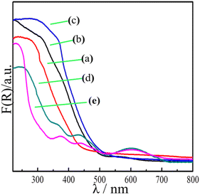 |
| | Fig. 5 UV-visible diffuse reflectance spectra of (a) flower-like In2O3, (b) In2O3/ZnGa2O4:Cr/1:0.5, (c) In2O3/ZnGa2O4:Cr/1:1, (d) In2O3/ZnGa2O4:Cr/1:2 and (e) ZnGa2O4:Cr. | |
3.4 Photocatalytic activity and mechanism
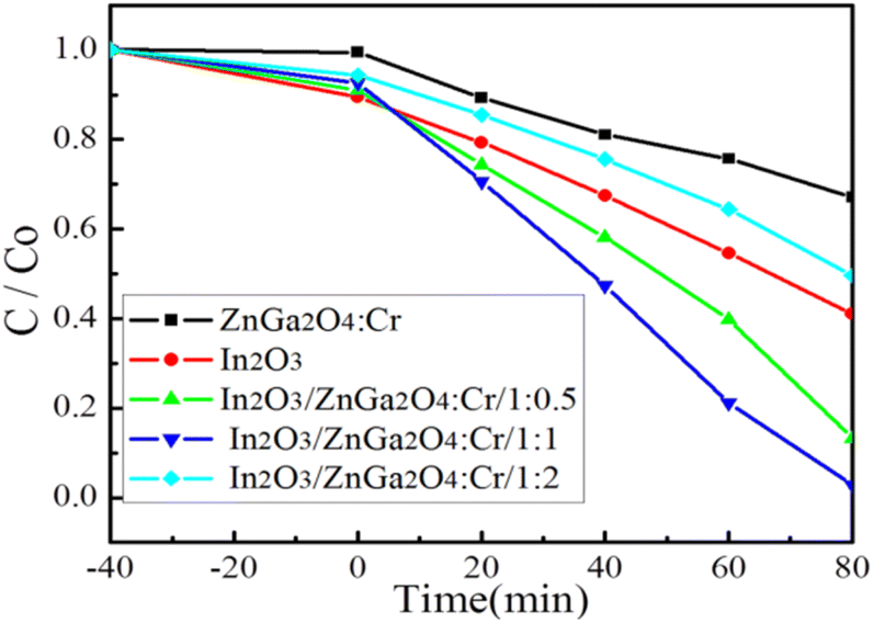
The photocatalytic activities of the In2O3/ZnGa2O4:Cr composites were evaluated via the degradation of RhB molecules under UV light irradiation. First, we established an adsorption–desorption equilibrium between the catalyst and dye molecules and stirred the suspension in the dark for 40 min. Fig. 6 shows that although pure ZnGa2O4:Cr shows no adsorption, both In2O3 and In2O3/ZnGa2O4:Cr have good surface adsorption properties. However, In2O3 is preferred to In2O3/ZnGa2O4:Cr because the flower-like In2O3 has a large specific surface area.44 Next, the samples were placed under UV irradiation by a mercury lamp at room temperature. In2O3/ZnGa2O4:Cr/1:1 exhibited good photocatalytic performance with a degradation efficiency of 98.8% after 80 min of irradiation with UV light. The experimental results indicated that the photocatalytic activity of In2O3/ZnGa2O4:Cr/1:1 was higher than that of the pure In2O3, ZnGa2O4:Cr, In2O3/ZnGa2O4:Cr/1:0.5 and In2O3/ZnGa2O4:Cr/1:2 samples that showed the degradation efficiencies of 59.3%, 33.2%, 86.7%, and 50.04%, respectively (Fig. 6). Under UV irradiation, the photo-degradation efficiency of In2O3/ZnGa2O4:Cr/1:1 for RhB was higher than that of other PLNPs in the literature (Table S1‡). The results indicate that the composite with the optimal In2O3/ZnGa2O4:Cr ratio of 1:1 shows good photocatalytic activity, while the photocatalytic activity decreases when the composite ratio is greater or lower than the optimal. This phenomenon has been extensively studied in type II heterostructures45–48 and non-metal and transition metal doped semiconductor systems,49,50 and is consistent with the interfacial charge transfer mechanism.
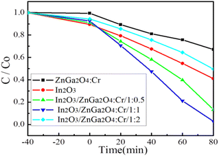 |
| | Fig. 6 Photo-degradation efficiency of In2O3/ZnGa2O4:Cr composites. | |
The surface-decorated ZnGa2O4:Cr in the In2O3/ZnGa2O4:Cr/1:1 composite acts as an efficient electron scavenger for In2O3, because its conduction band potential (−1.47 V vs. NHE) is lower than the CB level of In2O3 (−0.63 V vs. NHE). Consequently, the photo-excited electrons of ZnGa2O4:Cr were preferentially transported to In2O3, and suppressed charger combination in ZnGa2O4:Cr, providing abundant charge carriers and leading to the highest photocatalytic activity.25,35 Therefore, both the co-existing cubic and spinel phase In2O3/ZnGa2O4:Cr/1:1 heterojunction composites not only had good surface adsorption properties but also generated more electron–hole pairs. Subsequently, these electrons transferred to the surface of the composites, thus inhibiting the recombination of the photo-generated electron–hole pairs.
The recyclability of theIn2O3/ZnGa2O4:Cr/1:1 nanocomposites for photocatalytic RhB degradation was evaluated by five replicate experiments, as presented in Fig. S5,‡ showing that In2O3/ZnGa2O4:Cr/1:1 maintained more than 89% of its initial photocatalytic activity after five cycles. However, the XRD patterns and XPS spectra of In2O3/ZnGa2O4:Cr/1:1 did not show any notable differences before and after the photocatalytic cycles (Fig. S6 and S7‡). These results indicate that the In2O3/ZnGa2O4:Cr/1:1 composite maintains a favorable chemical state and crystal structure and is not photo-corroded.
The photocatalysis proceeded smoothly, as shown in Fig. 7. When the In2O3/ZnGa2O4:Cr composites were irradiated by UV light, the electrons generated in ZnGa2O4:Cr migrate to the CB of In2O3. This contributed to decreasing the electron–hole pair recombination. Furthermore, the generated electrons and holes are subsequently transferred to the surface of the composites. This process is favorable for electron–hole pair separation. The electrons subsequently transfer to the surface and react with oxygen to produce O2−˙.51 Then, the holes are captured by the hydroxyl groups (HO−) at the surface of the composites and produce hydroxyl radicals (HO˙).20–23 The obtained O2−˙ and HO˙ are strong oxidizing agents that degrade the RhB molecules. The mechanism of the photo-degradation reaction (Fig. 7) can be represented as follows:42
| | |
In2O3/ZnGa2O4:Cr + hv → hVB+ + eCB−
| (2) |
| | |
hVB+ + H2O → ˙HO + H+
| (3) |
| | |
Dye + (˙HO/O2−˙) → degradation
| (6) |
 |
| | Fig. 7 Schematic illustration of the photocatalytic mechanism of In2O3/ZnGa2O4:Cr composites. | |
3.5 Photoluminescence analyses
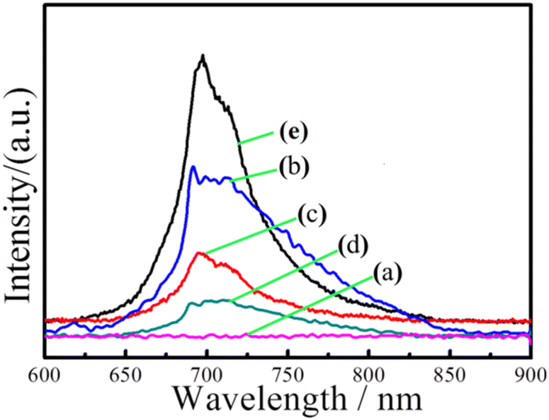
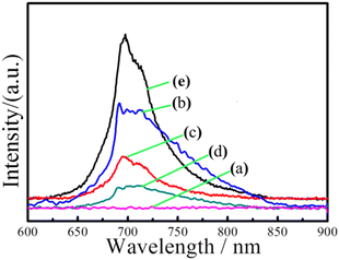
Fig. 8 shows the emission spectra of In2O3, ZnGa2O4:Cr, and In2O3/ZnGa2O4:Cr composites at an excitation wavelength of 254 nm. The ZnGa2O4:Cr and In2O3/ZnGa2O4:Cr composites give a NIR emission band peaking at 698 nm (assigned to the 2E → 4A2 transition of Cr3+) that is superimposed on a broad emission band in the 600–800 nm range (the 4T2 → 4A2 transition of disordered Cr3+).52 However, no NIR emission band peaks were observed for the pure flower-like In2O3. Moreover, the band peak intensity increased as the ZnGa2O4:Cr content increased from 0.5 to 2. Notably, the composite with the appropriate proportions of In2O3 and ZnGa2O4:Cr (In2O3/ZnGa2O4:Cr/1:1) also showed a certain intensity of NIR emission band peaks. The results demonstrated that the co-existing cubic and spinel phase In2O3/ZnGa2O4:Cr heterojunction composites accelerated electron transfer and were favorable for the separation of electron–hole pairs. Moreover, they showed a strong emission spectrum in the NIR. The photoluminescence excitation spectrum was monitored at 696 nm. Four main absorption bands were observed (Fig. S8‡). The strong band peak at approximately 260 nm was most likely due to the combination of the O–Cr charge transfer band and the ZnGa2O4 host excitation band.26 The bands had peaks at approximately 413, 473, and 555 nm and originated from the 4A2 → 4T1 (te2), 4A2 → 4T1 (te2), and 4A2 → 4T2 (te2) transitions that were assigned to the 3d intra-shell transitions of Cr3+, respectively.19
 |
| | Fig. 8 Emission spectra of (a) flower-like In2O3, (b) In2O3/ZnGa2O4:Cr/1:2, (c) In2O3/ZnGa2O4:Cr/1:1, (d) In2O3/ZnGa2O4:Cr/1:0.5 and (e) ZnGa2O4:Cr. | |
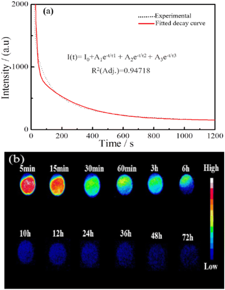
Fig. 9a shows the NIR afterglow decay curve of In2O3/ZnGa2O4:Cr monitored at 698 nm following excitation by 254 nm UV light for 5 min. The data were recorded for 20 min. Significant persistent luminescence signals could still be observed with the naked eye after 20 min. The decay curves of the NIR afterglow can be fitted well using the following three-exponential equation:53
| | |
I(t) = I0 + A1e−t/τ1 + A2e−t/τ2 + A3e−t/τ3
| (7) |
where
I0 is the initial intensity of the afterglow;
I(
t) is the intensity of the afterglow at time
t;
A1,
A2, and
A3 are constants; and
τ1,
τ2, and
τ3 are the derived lifetimes for the exponential components corresponding to the three different decay processes. Table S2
‡ shows the fitting results obtained using the above formula. The average photoluminescence lifetime (
τav) was 27.97 s. This result indicated that In
2O
3/ZnGa
2O
4:Cr had a long photoluminescence lifetime. We investigated the persistent luminescence decay of the In
2O
3/ZnGa
2O
4:Cr composite using a charge-coupled device camera at different times (10 min) of irradiation with 254 nm UV light. We still detected a non-negligible NIR luminescence signal (SNR = 3.1) from the In
2O
3/ZnGa
2O
4:Cr 72 h after stopping the UV irradiation (
Fig. 9b). This phenomenon indicates that the as-prepared composites exhibit great potential for round-the-clock photocatalytic applications.
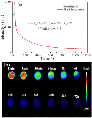 |
| | Fig. 9 (a and b) NIR afterglow decay curve and NIR afterglow images of the In2O3/ZnGa2O4:Cr/1:1 at different times. | |
4. Conclusions
A flower-like In2O3/ZnGa2O4:Cr/1:1 heterojunction composite with long NIR persistent luminescence was synthesized using an ethylene glycol-assisted hydrothermal method. The photocatalytic activity of the In2O3/ZnGa2O4:Cr composite was improved via the dispersion of the ZnGa2O4:Cr PLNPs on the flower petals of In2O3. The as-prepared In2O3/ZnGa2O4:Cr/1:1 composite exhibited good photocatalytic activity for RhB degradation, with a degradation efficiency of 98.8% after 80 min under UV light irradiation, which is higher than those of the pure In2O3, ZnGa2O4:Cr, In2O3/ZnGa2O4:Cr/1:0.5, and In2O3/ZnGa2O4:Cr/1:2 nanoparticles. Moreover, the composite exhibited long afterglow luminescence that lasted more than 72 h. Thus, the In2O3/ZnGa2O4:Cr composite shows great potential for use in round-the-clock photocatalytic applications.
Author contributions
Ailijiang Tuerdi: conceptualization, methodology, investigation, writing – original draft. Peng Yan: investigation. Fenggui He: investigation. Abdukader Abdukayum: conceptualization, methodology, project administration, resources, supervision, funding acquisition, writing – review & editing.
Conflicts of interest
There are no conflicts to declare.
Acknowledgements
This work is supported by the Scientific Research Program of the Higher Education Institution of Xinjiang (XJEDU2018I017), the Natural Science Foundation of Xinjiang Uygur Autonomous Region (2022D01E16), and Applied Technology Research and Development Program of Kashi Region (KS2020027).
Notes and references
- S. Papic, N. Koprivanac, A. L. Bozic and A. Metes, Dyes Pigm., 2004, 62, 291–298 CrossRef CAS.
- A. Latif, S. Noor, Q. M. Sharif and M. Najeebullah, J. Chem. Soc. Pak., 2010, 32, 115–124 CAS.
- T. B. Zanoni, M. Tiago, F. Faiao-Flores, S. B. de Moraes Barros, A. Bast, G. Hageman, D. P. de Oliveira and S. S. Maria-Engler, Toxicol. Lett., 2014, 227, 139–149 CrossRef CAS PubMed.
- H. Xu, S. Ouyang, L. Liu, P. Reunchan, N. Umezawa and J. Ye, J. Mater. Chem. A, 2014, 2, 12642–12661 RSC.
- W. Lei, T. Zhang, L. Gu, P. Liu, J. A. Rodriguez, G. Liu and M. Liu, ACS Catal., 2015, 5, 4385–4393 CrossRef CAS.
- N. Ding, X. Chang, N. Shi, X. Yin, F. Qi and Y. Sun, Environ. Sci. Pollut. Res., 2019, 26, 18730–18738 CrossRef CAS PubMed.
- Z. Wu, L. Na and D. Zhang, J. Porous Mater., 2014, 21, 157–164 CrossRef.
- W. Zeng, Y. Ren, Y. Zheng, A. Pan and T. Zhu, ChemCatChem, 2021, 13, 564–573 CrossRef CAS.
- L. Yang, X. Xiao, R. Zuo, Y. Lin and S. You, Mater. Sci. Forum, 2020, 993, 893–898 Search PubMed.
- L. Chuan, M. Tian, J. Wang, J. Wang, J. C. Yu and S. Yu, J. Catal., 2013, 310, 84–90 CrossRef.
- X. Zhang, S. Yu, Y. Liu, Q. Zhang and Y. Zhou, Appl. Surf. Sci., 2017, 396, 652–658 CrossRef CAS.
- L. Chen and W. Zhang, Appl. Surf. Sci., 2014, 301, 428–435 CrossRef CAS.
- Z. Lei, F. Yang, C. Yuan, L. Tai, C. Yao and D. Fang, Nano, 2021, 16, 2150018 CrossRef CAS.
- D. Wei, W. Jiang, H. Gao, X. Chuai, F. Liu, F. Liu, P. Sun, X. Liang, Y. Gao, X. Yan and G. Lu, Sens. Actuators, B, 2018, 276, 413–420 CrossRef CAS.
- M. Liu, P. Li, S. Wang, Y. Liu and H. Sun, J. Colloid Interface Sci., 2021, 587, 876–882 CrossRef CAS PubMed.
- H. Xu, Y. Wang, X. Dong, N. Zheng and X. Zhang, Appl. Catal., B, 2019, 257, 117932 CrossRef CAS.
- J. Mu, C. Shao, Z. Guo, M. Zhang and Y. Liu, J. Mater. Chem., 2011, 22, 1786–1793 RSC.
- J. Yin, S. Huang, Z. Jian, M. Pan, Y. Zhang, Z. Fei and X. Xu, Appl. Phys. A, 2015, 120, 1529–1535 CrossRef CAS.
- C. Zhang, Y. Huan, D. Sun and Y. Lu, J. Alloys Compd., 2020, 842, 155857 CrossRef CAS.
- F. Zhang, X. Li, Q. Zhao and D. Zhang, ACS Sustainable Chem. Eng., 2016, 4, 4554–4562 CrossRef CAS.
- L. Tien, C. Tseng, Y. Chen and C. Ho, J. Alloys Compd., 2013, 555, 325–329 CrossRef CAS.
- J. Gil-Rostra, F. Valencia and A. González-Elipe, J. Lumin., 2020, 228, 117617 CrossRef CAS.
- A. Abdukayum, C. Yang, Q. Zhao, J. Chen and X. Yan, Anal. Chem., 2014, 86, 4096–4101 CrossRef CAS PubMed.
- A. Tuerdi and A. Abdukayum, RSC Adv., 2019, 9, 17653–17657 RSC.
- X. Yang, J. Ma, R. Guo, X. Fan, P. Xue, X. Wang, H. Sun, Q. Yang and X. Lai, Mater. Chem. Front., 2021, 5, 5790–5797 RSC.
- V. Munusami, K. Arutselvan and S. Vadivel, Diamond Relat. Mater., 2020, 111, 108167 CrossRef.
- B. S. Bhupendra, K. Anxiu and Y. Mao, Chem. Commun., 2015, 51, 7372–7375 RSC.
- J. Y. Zhang, F. Pan, W. C. Hao, Q. Ge and T. M. Wang, Appl. Phys. Lett., 2004, 85, 5778–5780 CrossRef CAS.
- H. H. Li, S. Yin and T. Sato, Appl. Catal., B, 2011, 106, 586–591 CrossRef CAS.
- M. L. Chen, S. S. Li, L. Wen, Z. Xu, H. H. Li, L. Ding and Y. H. Cheng, J. Colloid Interface Sci., 2023, 629, 409–421 CrossRef PubMed.
- H. J. Sung, S. C. Jung and J. S. Kim, J. Nanosci. Nanotechnol., 2021, 21, 3729–3734 CrossRef CAS PubMed.
- R. Liu, Y. S. Yan and C. C. Ma, Front. Chem., 2018, 6, 69–78 CrossRef PubMed.
- F. Locardi, E. Sanguineti, M. Fasoli, M. Martini, G. A. Costa, M. Ferretti and V. Caratto, Catal. Commun., 2016, 74, 24–27 CrossRef CAS.
- J. J. Zhou, J. Huang, Y. Xia, H. Ou and Z. J. Li, Sci. Total Environ., 2019, 6, 134342–134347 Search PubMed.
- B. Han, J. Wang, W. Yang, X. Chen and X. Wei, Sens. Actuators, B, 2020, 309, 127788 CrossRef CAS.
- S. Gao, C. Dong, L. Hong, K. Xiao, X. Pan and X. Li, Electrochim. Acta, 2013, 114, 233–241 CrossRef CAS.
- S. Zhao, Y. B. Shen, P. F. Zhou, F. L Hao, X. Y. Xua, S. L. Gaoa, D. Z. Wei, Y. X. Ao and Y. S. Shen, Sens. Actuators, B, 2020, 308, 127729–127738 CrossRef CAS.
- I. Lopez, A. D. Utrilla, E. Nogales, B. I. Mendez and J. Piqueras, J. Phys. Chem. C, 2012, 116, 3935–3943 CrossRef CAS.
- L. Yang, Y. Z. Hong, E. Liu, X. Zhang, L. Y. Wang, X. Lin and J. Y. Shi, Sep. Purif. Technol., 2021, 263, 118366–118376 CrossRef CAS.
- Q. Zhu, Y. K Sun, S. Xu, Y. L Li, X. L. Lin and Y. L. Qin, J. Hazard. Mater., 2020, 382, 121098–121101 CrossRef CAS PubMed.
- Y. J. Chen, G. H. Tian, Z. Y. Ren, K. Pan, Y. H. Shi, J. Q. Wang and H. G. Fu, ACS Appl. Mater. Interfaces, 2014, 6, 13841–13849 CrossRef CAS PubMed.
- A. Tuerdi, A. Abdukayum and C. Pei, Mater. Lett., 2017, 209, 235–239 CrossRef CAS.
- Q. Li, L. Zhang, C. Tang, P. Zhao and J. Yin, Int. J. Hydrogen Energy, 2020, 45, 6621–6628 CrossRef CAS.
- G. Zhu, M. Hojamberdiev, K. I. Katsumata, N. Matsushita, K. Okada, P. Liu and J. Zhou, Adv. Mater. Res., 2013, 747, 635–638 CAS.
- C. W. Tsao, M. J. Fang and Y. J. Hsu, Coord. Chem. Rev., 2021, 438, 213876–213905 CrossRef CAS.
- T. H. Lai, K. I. Katsumata and Y. J. Hsu, Nanophotonics, 2020, 10, 777–795 CrossRef.
- Y. H. Chiu, T. M. Chang, C. Y. Chen, M. Sone and Y. J. Hsu, Catalysts, 2019, 9, 430–445 CrossRef CAS.
- Y. F. Lin and Y. J. Hsu, Appl. Catal., B, 2013, 130, 93–98 CrossRef.
- S. Lee, Y. Lee and G. N. Panin, ACS Appl. Mater. Interfaces, 2017, 5, 1557–1577 Search PubMed.
- M. J. Fang, C. W. Tsao and Y. J. Hsu, J. Phys. D: Appl. Phys., 2020, 53, 143001–143032 CrossRef CAS.
- M. Elavarasan, K. Uma and K. Yan, J. Taiwan Inst. Chem. Eng., 2021, 120, 169–177 CrossRef CAS.
- A. Abdukayum, A. Tuerdi, R. Abdurahman, M. Tursun and N. Nurmat, J. Inorg. Mater., 2016, 31, 1363–1369 CrossRef.
- A. Abdukayum, J. Chen, Q. Zhao and X. Yan, J. Am. Chem. Soc., 2013, 135, 14125–14133 CrossRef CAS PubMed.
Footnotes |
| † Dedicated to the 60th anniversary of Kashi University and the 40th anniversary of chemistry at Kashi University. |
| ‡ Electronic supplementary information (ESI) available. See DOI: https://doi.org/10.1039/d2ra05646a |
|
| This journal is © The Royal Society of Chemistry 2022 |
Click here to see how this site uses Cookies. View our privacy policy here. 
 Open Access Article
 This Open Access Article is licensed under a Creative Commons Attribution-Non Commercial 3.0 Unported Licence
 *
*