DOI:
10.1039/D2RA04932E
(Paper)
RSC Adv., 2022,
12, 31950-31958
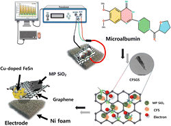
A flexible mesoporous Cu doped FeSn–G–SiO2 composite based biosensor for microalbumin detection†
Received
7th August 2022
, Accepted 2nd November 2022
First published on 8th November 2022
Abstract
A new mesoporous Cu-doped FeSn–G–SiO2 (CFSGS) based biosensor was developed for the detection of microalbumin in urine samples. The mechanically flexible FeSn modified sensor was fabricated at room temperature. These demonstrations highlight the unexplored potential of FeSn for developing novel biosensing devices. It is extremely sensitive and selective. Surfactant-aided self-assembly was used to synthesise the mesoporous CFSGS. The large surface area due to the mesopore presence in the CFSG surface that has been composited inside the mesoporous SiO2 boosted the electrochemical detection. The linear range and detection limit of microalbumin under optimum circumstances were 0.42 and 1 to 10 μL, respectively. This easily fabricated mesoporous CFSGS provided a fast response with high sensitivity, and good selectivity. The sensor's reusability and repeatability were also quite high, with just a 90 percent drop after 4 weeks of storage at ambient temperature. The biosensor also demonstrated high selectivity against typical potential interfering chemicals found in urine (ascorbic acid, urea, and sodium chloride). The good performance of the mesoporous CFSGS biosensor was validated by measuring microalbumin, and the findings indicated that this sensing device performed very well.
1. Introduction
Human albumin is a protein that is usually present in blood, and when this protein gets into the urine due to kidney disease, it is referred to as microalbumin. Microalbumin is effective in determining chronic renal disease, endothelial dysfunction, and diabetes complications early on.1 Because of the importance of detecting microalbumin, many research groups have developed various detection systems, such as immunoturbidimetric, spectrophotometry, immune resonance scattering, radioimmunoassay, immunonephelometry, chemiluminescence immunoassay, fluorescence immunoassay, HPLC, electrophoresis, and biosensors.2 Antibody-based assays and enzymes have to be labeled for use in these procedures. Although the introduction of antibodies and enzymes has enhanced the sensitivity and selectivity, the high cost and instability of enzymes3 limit the use of these technologies. Among these, electrochemical sensors are the most widely used. Because of their excellent sensitivity, very low detection limit, and outstanding selectivity, electrochemical sensors are used for microalbumin detection.4–7 Iron-based alloys and compounds have provided an excellent foundation for biosensing applications; iron–tin alloy-based sensors are capable of electrically detecting a field, and are becoming increasingly important for sensing applications.8 Improved biosensing elements are one field of biosensor development. Many natural sensing components have been developed that imitate equivalents as a result of their high cost and sensitivity to environmental changes. As a result of the significant anomalous Hall effect, Fe–Sn nanocrystalline films are suitable for magnetic sensors that require high sensitivity, as well as thermal stability. The anomalous Hall effect (AHE) occurs in solids with broken time-reversal symmetry, typically in a ferromagnetic phase, as a consequence of spin–orbit coupling.9 Due to the modest temperature-dependency of the anomalous Hall responses, these Fe–Sn composites show a significant advantage over semiconductors as a sensor. In addition, a sensor on an organic substrate could be developed using the room temperature (RT) fabrication method.8 Graphene-based electrochemical sensors have performed very well. These consist of a single layer of graphite, a honeycomb lattice of sp2 linked carbon atoms, with an atom thickness of one atom. Biomolecules are also effectively captured by this surface-to-volume ratio and the improved stacking contact between hexagonal structures and carbon-based ring structures.10–13 Research on the absorbability of biosensors using graphene is prevalent.14–17 In addition, Cu-doping in nanoparticles is widely regarded as an effective method to enhance device performance by increasing electrical conductivity.18 The combination of mesoporous SiO2 with graphene was used to improve biosensor performance as a channel material by improving the surface area and active site.19,20 Porous SiO2 provides a high specific surface area and has an effect of increasing the amount of adsorption of the material to be sensed. In addition, the chemical reaction active site causes an effect of increasing reactivity with the substance to be sensed.21–23 The Cu-doping exhibited excellent peroxidase-mimicking catalytic activity and high affinity towards proteins and microbiomedia.24
The fabrication of high-performance electrode materials without biological or chemical receptor labeling remains a significant challenge for microalbumin-sensing systems. Because of the possible interactions between microalbumin, it is challenging to detect microalbumin in a timely and sensitive manner. Based on the inadequacies of earlier approaches, we developed a mesoporous Cu-doped FeSn–G–SiO2 (CFSGS) based composite without antigen antibody binding and receptor labeling in this study. For CFSGS nanocomposite, we suggest a basic self-assembly method. The nanocomposites are confirmed by XRD, SEM, BET, HR-TEM, Raman, XPS, and N2 adsorption/desorption. As a result, this study proposes a label-free, sensitive, selective, cost-effective, and quick electrochemical sensing platform for microalbumin detection. A CFSGS sensor with selectivity and reproducibility for microalbumin detection has not previously been used in an electrochemical platform.
2. Experimental
2.1 Materials and instruments
Copper(II) sulfate pentahydrate (CuSO4·5H2O), SnCl2·2H2O, and Pluronic F-127 were purchased from Duksan Pure Chemicals Co. Ltd., Korea. Iron(II) chloride, tetrahydrate (FeCl2·4H2O) was obtained from Yakuri Pure Chemicals Co. Ltd., Japan. Ethanol, natural graphite powder, hydrochloric acid (HCl, 36 wt%), sulfuric acid (H2SO4, 97%), and potassium permanganate (KMnO4) were purchased from Sigma-Aldrich USA. Tetraethyl orthosilicate (SiC8H20O4), ethylene glycol (99.5%), and microalbumin were purchased from Samchun Pure Chemical Co., Ltd., Korea. All solutions were prepared using distilled water. Electrochemical measurements were made using a CV graph, and measured by PGP201 Potentiostat (A41A009), Volta lab™, Denmark. Platinum and Ag/AgCl electrode were employed as a counter electrode and reference electrode, respectively.
2.2 Synthesis of mesoporous Cu-doped FeSn (CFS)
A self-assembly approach was used to generate Cu-doped FeSn nanoparticles, which were then characterized. To prepare iron(II) chloride (FeCl2), 200 mL of ethyl alcohol was first dissolved in continuous stirring at RT. After 30 min of stirring, a total of 400 mL of doubly deionized water and tin(II) chloride (SnCl2·2H2O) were added. Doping was accomplished by adding copper(II) sulfate pentahydrate (CuSO4·5H2O). When it comes to precursor reagents, the molar ratio was established at 1![[thin space (1/6-em)]](https://www.rsc.org/images/entities/char_2009.gif) :1. In the next step, an ethanol solution of surfactant (6.5 g of Pluronic F127 block copolymer diluted in 500 mL of ethanol) was added. After 6 h of stirring at 60 °C, an aqueous sol–gel solution was formed, and allowed to evaporate overnight. Then, it was calcined at 700 °C (ramp rate: 1 °C min−1) for 3 h at a rate of 1 °C min−1.
:1. In the next step, an ethanol solution of surfactant (6.5 g of Pluronic F127 block copolymer diluted in 500 mL of ethanol) was added. After 6 h of stirring at 60 °C, an aqueous sol–gel solution was formed, and allowed to evaporate overnight. Then, it was calcined at 700 °C (ramp rate: 1 °C min−1) for 3 h at a rate of 1 °C min−1.
2.3 Synthesis of mesoporous Cu-doped FeSn–G (CFSG)
In this experiment, after 0.15 g of synthesized graphene oxide (GO) was added to 600 mL of water, the reaction mixture was exposed to high-intensity ultrasonication for 40 min at RT. The sonicated graphene oxide solution was added to the solution of Cu-doped FeSn while the solution was being stirred continuously during the process. Next, 60 mL of 2 M sodium hydroxide solution was dropwise added to the sonicated precursor mixture, to achieve the desired pH. The resultant mixture was then agitated for 3 h at 100 °C, to ensure that graphene and CFS were properly combined. After that, it was heated to 700 °C for 4 h.
2.4 Synthesis of mesoporous Cu-doped FeSn–G–SiO2 (CFSGS)
The Cu-doped FeSn–G solution was added drop-by-drop to a beaker containing 0.13 g of synthesized mesoporous silica,25 and the mixture was stirred at 100 °C for 24 h. After stirring, the mixture was exposed to 1 h of ultrasonication. Next, the powder was filtered, rinsed with ethanol, and dried at 65 °C overnight. Finally, it was calcined at 700 °C at a rate of 10 °C min−1 for 5 h at a temperature of 700 °C.
2.5 Fabrication of mesoporous Cu-doped FeSn–G–SiO2 (CFSGS) electrode
The sensors for Cu-doped FeSn–G–SiO2 (CFSGS), Cu-doped FeSn–G (CFSG), and Cu-doped FeSn (CFS) were all working electrodes constructed on Ni foam. The electrochemical paste deposition was carried out on Ni foam with a surface area of (2–2.5) cm2. Next, the Ni foam was coated with CFSGS. CFSG and CFS were mixed with ethyl cellulose to make a paste, which was then dried. The dried mixture was next sintered for 1 h at 90 °C. Pressure was then applied to the electrode surface to achieve a homogeneous surface. All the samples were covered with a 4 mm thick layer of paste. The thickness, size, and coating of all the samples were the same.
2.6 Characterization of materials
In this study, the phase structure and purity of the mesoporous Cu-doped FeSn–G–SiO2 (CFSGS) nanocomposite were investigated by X-ray diffraction (XRD; Rigaku, Japan) with Cu-Kα radiation (λ = 1.5406 Å) at 40 kV and 30 mA across a 2θ range of (20–70)°. Scanning electron microscopy (SEM) was used to examine the morphologies of the samples that were acquired. EDS analysis was performed by SEM (JSM-76710F, JEOL, Japan), transmission electron microscopy (TEM) (JEM-4010, JEOL, Japan), and high-resolution TEM (HRTEM) (JSM-76710F, JEOL, Japan), operating at an accelerating voltage of 300 kV. X-ray photoelectron spectroscopy (XPS), Diffuse Reflectance Spectroscopy (DRS), and Raman spectroscopy (RAMAN) analyses were performed utilizing WI Tec. alpha 300 series. Porous characterization of CFSGS structure was performed with a full analysis of N2 adsorption/desorption tests (BELSORP-max, BEL Japan Inc.). Electrochemical measurements were made by PGP201 Potentiostat (A41A009), Volta lab™, Denmark.
2.7 Electrochemical measurements
During this experiment, an electrochemical setup with three electrodes was employed. The counter electrode was platinum, while the reference electrodes were Ag/AgCl (CV). Aqueous buffer solution was used to test electrolytes. The following eqn (1)26 was used to determine the detection limit:where, the N is the slope of the calibration curve, and SD is the standard deviation. CV measurements were made from (−0.3 to +0.2) V versus Ag/AgCl at 10 mV s−1.
3. Results and discussion
3.1 Characterization of the mesoporous Cu-doped FeSn–G–SiO2 (CFSGS) sample
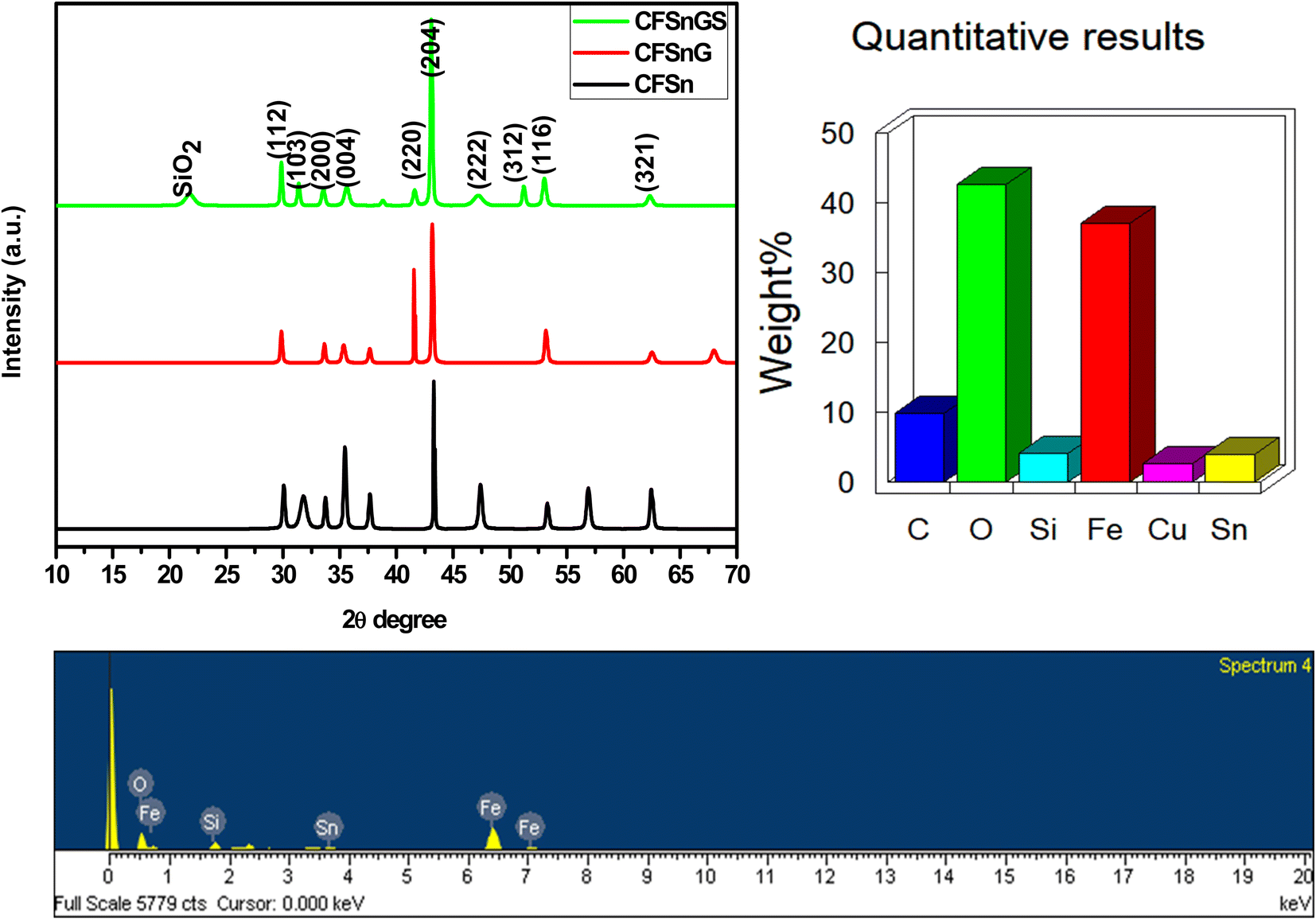
Crystallographic structure may be determined with high precision using X-ray diffraction (XRD), a non-destructive approach. Fig. 1 shows the X-ray diffraction patterns of the mesoporous Cu-doped FeSn–G–SiO2 (CFSGS). The XRD pattern of the mesoporous CFSGS shows diffraction peaks associated with the (112), (103), (200), (004), (220), (204), (222), (312), (116), and (321) crystalline planes. The positions and intensities of the diffraction peaks were confirmed to be identical, and no secondary phases were discovered. All diffraction peaks correspond to the stannite structure in tetragonal space.27 These results demonstrate that the effects of Cu-doping on the structural properties were negligible. Quantitative analysis of the CFSGS discovered the weight percentages of Cu, Sn, Fe, C, O, and Si to be (5.20, 8.80, 35.53, 9.29, 45.07, and 5.30) wt%, respectively, as shown in Fig. 1.
 |
| | Fig. 1 XRD patterns of CFS, CFSG and CFSGS, EDS spectra of CFSGS. | |
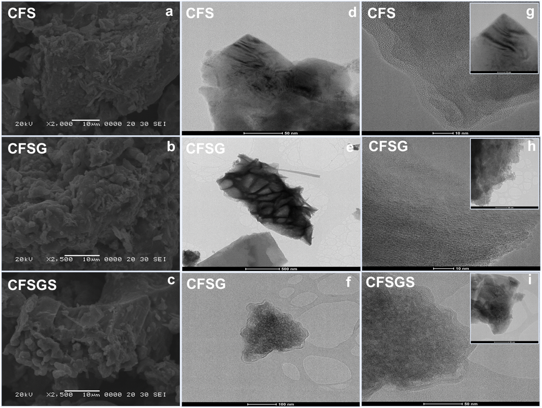
Fig. 2 shows the SEM images of the mesoporous Cu-doped FeSn (CFS), Cu-doped FeSn–G (CFSG), and Cu-doped FeSn–G–SiO2 (CFSGS). The illustration in Fig. 2(a) demonstrates that because of the accumulation of smaller particles, the CFS is shown to be of sparse and porous agglomeration.28 In addition, Fig. 2(b) shows that following the combination of graphene and CFS, the surface particles of CFSG begin to develop, and the surface of the agglomerates becomes smoother. When coupled with mesoporous SiO2, the surface particles of CFSGS become smoother as a result of the smoothing effect shown in Fig. 2(c). The TEM and HRTEM images in Fig. 2(d)–(i) provide high-resolution qualitative analysis of the CFS, CFSG, and CFSGS. Fig. 2 shows that the distribution of nanoparticles in the sample is exactly the same as the SEM image. Fig. 2(d) shows a scattering of CFS particles in cubic spheres. CFSG nanoparticles are also shown in Fig. 2(e) after graphene integration, which reveals an uneven distribution of nanosized CFSG cubic spheres, and a thin graphene layer structure. As a further step, Fig. 2(f) shows that combined with mesoporous SiO2 to produce CFSGS particles, the CFSGS displays excellent dispersion and stability. In addition, the corresponding HRTEM images of CFS, CFSG, and CFSGS are shown in Fig. 2(g)–(i), respectively.
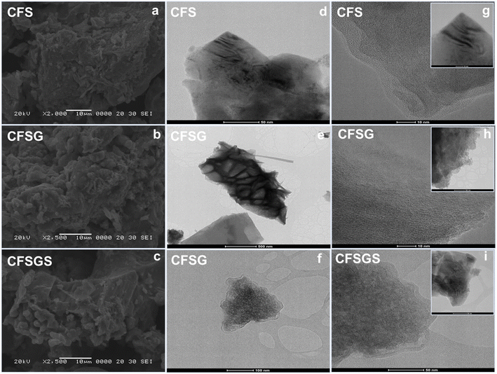 |
| | Fig. 2 (a) SEM image of CFS, (b) CFSG and (c) CFSGS; (d) TEM image of CFS, (e) CFSG and (f) CFSGS; (g) HRTEM images of CFS, (h) CFSG and (i) CFSGS. | |
Fig. 3(a) depicts the surface characteristics of the mesoporous Cu-doped FeSn–G–SiO2 (CFSGS) as determined by the N2 adsorption–desorption isotherms. Fig. 3(b)–(d) show the nitrogen sorption isotherms in the CFSGS sample, as well as the surface area plot, t-plot, and pore distribution curves, demonstrating that the adsorption displayed a type IV isotherm, which is characteristic of mesoporous materials. There is also a type H2 hysteresis loop with a P/P0 of (0.7 to 0.9). The pore size distribution of CFSGS was determined to be 2.77 nm, which is larger than 2 nm, suggesting the presence of mesopores in the adsorbent.29
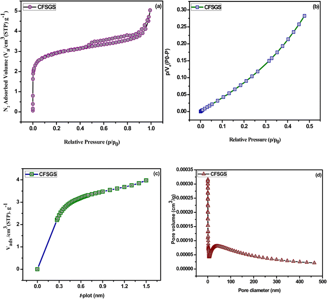 |
| | Fig. 3 (a) Nitrogen adsorption–desorption isotherms, (b) surface area plot, (c) t-plot and (d) pore distribution of CFSGS sample. | |
The surface chemical compositions of the mesoporous Cu-doped FeSn–G–SiO2 (CFSGS) were determined by XPS analysis in this study. Fig. 4 shows the XPS survey that confirms the Fe, Cu, Sn, C, O, and Si elements. The XPS analysis of the CFSGS nanocomposite confirms the chemical states and surface nature of the material. Fig. S1(a) of the ESI† shows the XPS spectrum of Cu 2p, which reveals the Cu 2p3/2 and Cu 2p1/2 core peaks that were produced at 932.89, 934.68 and 952.15, and 954.56 eV, respectively.30 Fig. S1(b) of the ESI† shows the main peaks of Fe 2p3/2 at 711.69 eV and Fe 2p1/2 at 726.09 eV, which accord with the typical Fe3O4 peaks.31 Fig. S1(c) of the ESI† shows the Sn 3d that demonstrates the binding energies of Sn 3d5/2 and Sn 3d3/2 of about 486.86, and 486.98 and 495.06 eV, respectively.29 Fig. S1(d) of the ESI† shows the C 1s spectra, with peaks at (284.55, 285.88, and 288.05) eV, which were interpreted as C–C, C–O, and O–C![[double bond, length as m-dash]](https://www.rsc.org/images/entities/char_e001.gif) O bonding, respectively. Fig. S1(e) of the ESI† depicts the O1s spectra with peaks at 532.82 and 534.02 eV, which were ascribed to C–O bonding. Fig. S1(f)† shows Si 2p core level doublet peaks Si 2p at 103.02 and 99.95 eV that are observed for the CFSGS sample, thus confirming the presence of SiO2 decorating the Cu-doped FeSn–G surface.25,26,31
O bonding, respectively. Fig. S1(e) of the ESI† depicts the O1s spectra with peaks at 532.82 and 534.02 eV, which were ascribed to C–O bonding. Fig. S1(f)† shows Si 2p core level doublet peaks Si 2p at 103.02 and 99.95 eV that are observed for the CFSGS sample, thus confirming the presence of SiO2 decorating the Cu-doped FeSn–G surface.25,26,31
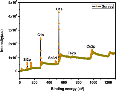 |
| | Fig. 4 XPS spectra of CFSGS survey that confirms the Ba, Fe, Cu, Sn, C, O, and Si elements. | |
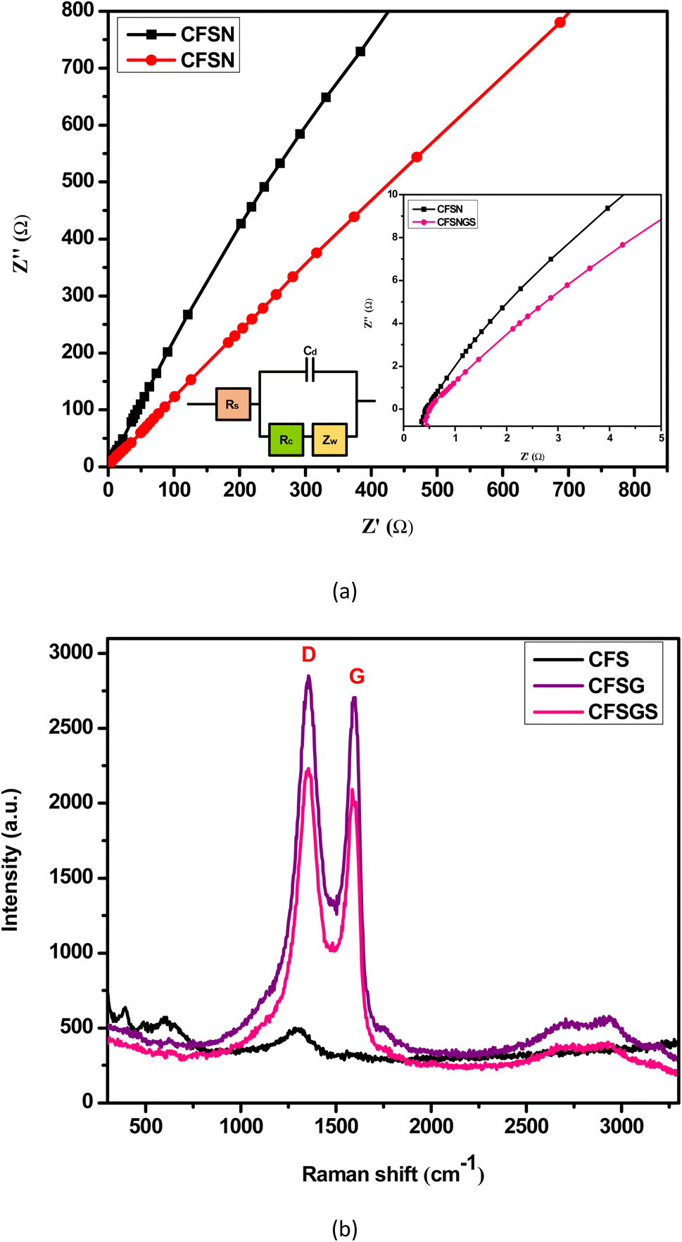
To prove the feasibility of this biosensing strategy, the EIS was used to study the interface properties of different modified electrodes. Fig. 5(a) depicts the Nyquist plots of different modified electrodes. The EIS data were fitted to a Randles equivalent circuit in Fig. 5(a) (inset), which included the resistance of the electrolyte solution (Rs), the charge transfer resistance (Rct), Warburg impedance, and the capacity of the double layer.32 Electrochemical impedance spectroscopy (EIS) studies of the mesoporous Cu-doped FeSn (CFS), Cu-doped FeSn–G (CFSG), and Cu-doped FeSn–G–SiO2 (CFSGS) electrodes were performed to determine the resistance to electron transfer during the sensing process. To ensure homogeneity, EIS measurements were taken at full charge following the third discharge/charge cycle. In general, the resistance and charge-transfer impedance on the electrode–electrolyte interface are assigned to the high-frequency semicircle and the medium-frequency semicircle, respectively. Fig. 5(a) shows that the charge-transfer resistance of CFSGS electrode is lower than that of CFSG and CFS, indicating that CFSGS electrode has superior electronic and ionic conduction. It is widely known that electrochemical performance is improved when electron and ion conductivity is improved during cycling of an active material, which is compatible with the improvement of the cycle performance of such an electrode at a current density.3
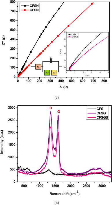 |
| | Fig. 5 (a) Nyquist plots were fitted to a Randles equivalent circuit (inset), (b) Raman spectra of CFS, CFSG and CFSGS. | |
Due to the sensitive nature of Raman spectroscopy in probing the local structure of atoms in materials, Raman analyses have been carried out to better understand the structure of the mesoporous Cu-doped FeSn (CFS), Cu-doped FeSn–G (CFSG), and Cu-doped FeSn–G–SiO2 (CFSGS), as shown in Fig. 5(b). Conjugation and carbon–carbon double bonds formed Raman spectra of high intensity. Throughout the study, D and G bands (ID/IG) were employed to assess the domain disorder and size of sp2 domains. The G band at 1565 cm−1 was related to sp2 C atoms and E2g phonons, while the D band at 1362 cm−1 was linked to the A1g breathing mode.33 The D band may be caused by empty spaces, particle boundaries, and amorphous carbon species.33 The intensity ratios of these two bands were compared for quality. Defect locations of GO may inhibit nanoparticle aggregation, and improve interactions with CFSG nanocomposites and CFSGS nanocomposites.
3.2 Electrochemical behavior of the mesoporous Cu-doped FeSn–G–SiO2 (CFSGS)
Fig. 6(a) shows the electrochemical behavior of the CV for the mesoporous Cu-doped FeSn (CFS), Cu-doped FeSn–G (CFSG), and Cu-doped FeSn–G–SiO2 (CFSGS), obtained at a scan rate of 10 mV s−1. The current density for the bare CFS electrode was 8.0 × 10⁻⁵ mA cm−2, and for the CFSG electrode was 1.0 × 10⁻⁴ mA cm−2. Fig. 6(b) shows that the bare CFSGS electrode CV response was 8.0 × 10⁻⁴ mA cm−2. The CV response at the bare CFS electrode shows low electron transfer efficiency; after combination with graphene, the bare CFSG electrode response was increased due to the high electron transfer properties of graphene.13 However, significant enhancement in the response was observed for the bare CFSGS electrode after combination with mesoporous SiO2, because of increasing the effective surface area and facilitating the charge-transfer process.30 These methods indicate that the combination of graphene and SiO2 used to modify the porous structure of the CFSGS working electrode had a significant impact on the electrochemical performance.30 In Fig. 6(c), the CFSGS CV response to microalbumin is significantly reduced, with a current density of 1.0 × 10⁻⁵ mA cm−2, compared to CFSG and CFS current densities of (4.0 and 5.0) × 10−5 mA cm−2, respectively. It is expected that the microalbumin would hinder electron transport on electrode surfaces. Thus, when CFSGS electrode was exposed to the microalbumin, the current density was decreased, compared to CFS and CFSG, while adding SiO2 to the surface of the CFSG electrode enhanced the surface area and active site; however, attaching microalbumin to the CFSGS surface drastically lowered the electron transfer rate, owing to active site blockage by hydrogen bonding (Scheme 1).26 This discovery highlights the need to modify the surface of CFSGS with conductive nanomaterials to capture the very tiny signals generated by biological activities on the electrode surface for biosensing.26
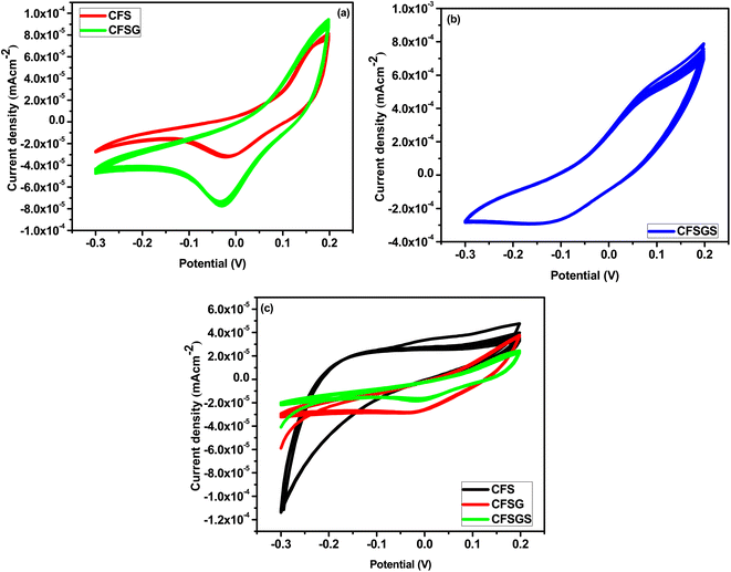 |
| | Fig. 6 (a) Cyclic voltammogram of CFS, CFSG and (b) CFSGS electrode in PBS in the absence of microalbumin at a scan rate of 10 mV s−1 (pH 7.0); (c) cyclic voltammogram of CFS, CFSG and CFSGS sample with 50 μL microalbumin in PBS at scan rate of 10 mV s−1 (pH = 7.0). | |
 |
| | Scheme 1 Microalbumin sensing mechanism with electrochemical performance system. | |
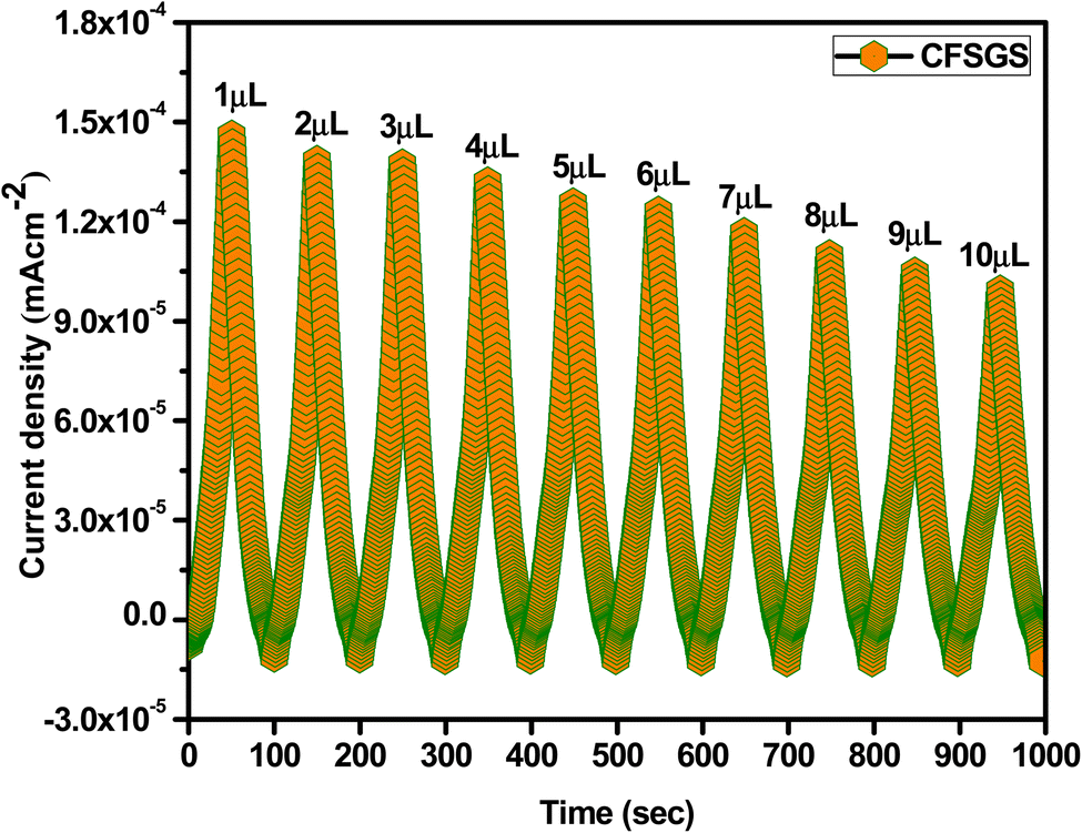
In addition, we assessed the concentration dependency of the microalbumin with mesoporous Cu-doped FeSn–G–SiO2 (CFSGS) electrode. Fig. 7 shows the results. The CFSGS electrode was employed to achieve a proper response in the electrochemical detection of microalbumin with different concentrations. The measured current decreased as the concentration of microalbumin increased. Within its detection range, the sensor displayed a strong linear relationship. The biosensor indicated rapid, stable, and increasing current responses over the entire concentration range. When the microalbumin concentration was increased at the electrode, the current values decreased. Electrons were transferred from the electrolyte to the electrode surface by redox media, and interrupted by microalbumin.26
 |
| | Fig. 7 Concentration dependency of microalbumin with CFSGS electrode in PBS at scan rate of 10 mV s−1 (pH = 7.0). | |
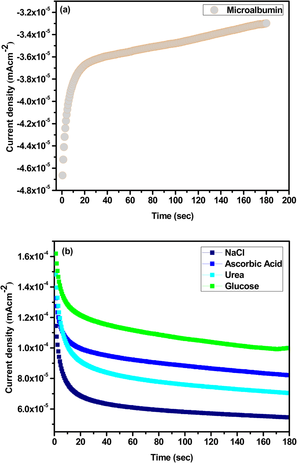
Fig. 8(a) shows the selectivity of the microalbumin with mesoporous Cu-doped FeSn–G–SiO2 (CFSGS) electrode, and Fig. 8(b) at the same range, adding NaCl, ascorbic acid, urea, and glucose as interference. To investigate the specificity of the biosensor toward microalbumin, the effects of some commonly found interferents in real samples, such as NaCl, ascorbic acid, urea, and glucose, were determined by the fabricated biosensor in 0.1 M PBS solution (pH 7.0), the selectivity of the biosensor being measured in the presence of the same ratio of each NaCl, ascorbic acid, urea, and glucose, respectively. The addition of interference had no influence on the current density, but the current density of microalbumin was −3.2 mA cm−2, indicating that the CFSGS showed high specificity for microalbumin detection. The current density of the other interfering compounds was approximately the same, which showed no interaction of these biomolecules. The results showed the CFSGS biosensor had strong anti-interference ability.26 Based on fading nanocurcumin in an alkali solution, human serum albumin (HSA), bovine serum albumin (BSA), transferrin (TRF), immunoglobulin G (IgG), fibrinogen (Fb) and casein (Cas) are good target materials for sensing carrier protein.34
 |
| | Fig. 8 (a) Selectivity of CFSGS sample with microalbumin. (b) The relative response was measured with NaCl, ascorbic acid, urea, and glucose as interference. | |
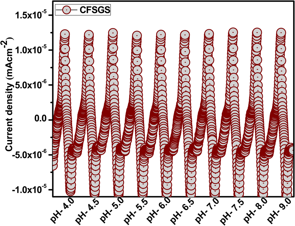
As a general rule, the highest possible level of biosensor activity is considered to be the most acceptable. In the case of CFSGS, the pH 7.0 value provided the highest response. Higher pH levels resulted in a lower reaction. Furthermore, at more acidic pH levels, the biosensor response was only approximately half as active as it had been at higher pH values. Based on these findings, it can be concluded that the pH of the working buffer may be considered an essential component in influencing the sensitivity of the biosensor to CFSGS. As a result, it was determined that pH 7.0 was the best pH for the biosensor to use. The pH of the electrolyte may influence the modified electrode's peak potential and peak current. It is preferable to analyze the electrode reaction's proton-to-electron ratio. Fig. 9 depicts the effect of pH at a scan rate of 10 mV s−1 over the pH range pH = (4 to 9). The maximum mesoporous Cu-doped FeSn–G–SiO2 (CFSGS) current response was obtained at pH 9, making it excellent for the identification of microalbumin.30
 |
| | Fig. 9 The pH dependence of CFSGS electrode at a scan rate of 10 mV s−1 over the pH range pH = (4 to 9). | |
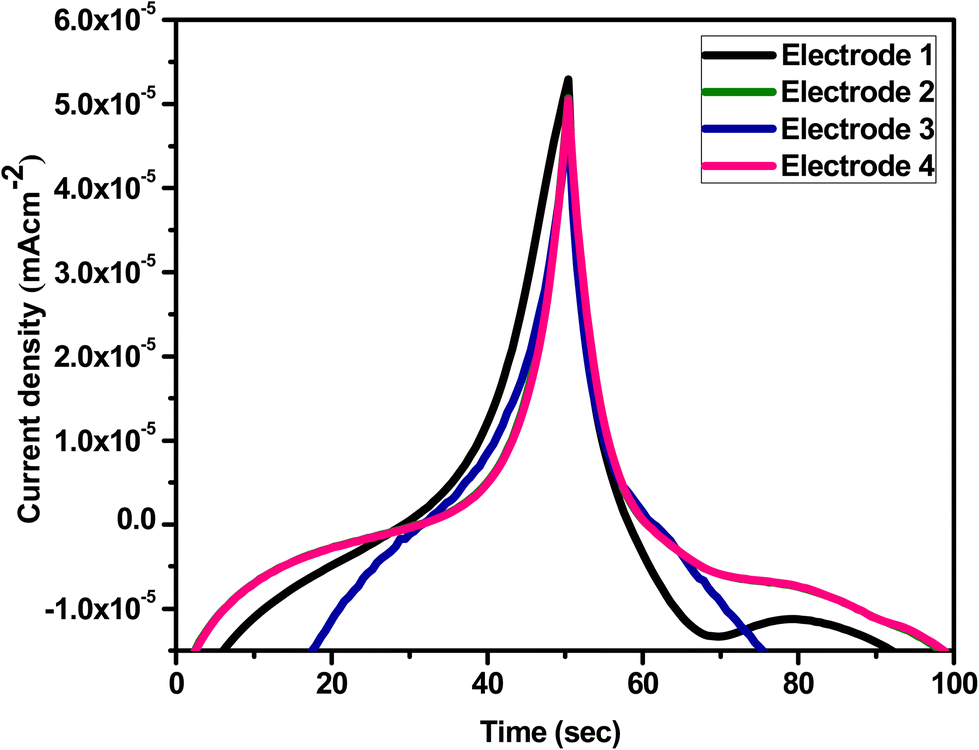
Furthermore, reproducibility is a key aspect for the microalbumin sensor. Four electrodes were tested under comparable conditions to determine the reproducibility of the mesoporous Cu-doped FeSn–G–SiO2 (CFSGS) electrode employing 50 μL microalbumin, as shown in Fig. 10. Fig. 11 shows the relationship between the current density and time response with the concentration condition of C = 1 μL and the pH = 7.0, at a scan rate of 10 mV s−1. These relationships were measured using three types of CFS, CFSG, and CFSGS electrodes under measurement conditions similar to the primary conditions in Fig. 7. As time increased, a current density value was decreased, and the electrode using the CFSGS electrode active material had the highest current density value, and it seems that the sensing response per unit time was the best. As suggested above, it is thought that porous SiO2 will increase the sensing effect and Cu-doped FeSn will increase the current density value together with graphene. This fact shows that CFSG has a better current density value than CFS, which is believed to be due to the excellent electron transfer effect of graphene.
 |
| | Fig. 10 Reproducibility of four CFSGS electrodes for detection of 50 μL microalbumin in PBS at scan rate of 10 mV s−1 (pH = 7.0) with continuity. | |
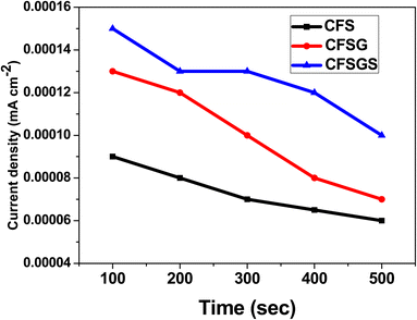 |
| | Fig. 11 Current density and time response of microalbumin with CFS, CFSG and CFSGS electrodes in PBS at scan rate of 10 mV s−1 (C = 1 μL, pH = 7.0). | |
4. Conclusions
We developed an electrochemical sensor based on the synergistic effect of mesoporous Cu-doped FeSn–G–SiO2 (CFSGS) for the ultrasensitive, rapid, and easy detection of microalbumin. This is the first report of a CFSGS-based biosensor with an electrochemical detector for microalbumin. On the developed biosensor, the combination of graphene, mesoporous semiconductive Cu-doped FeSn (CFS), and mesoporous SiO2 offered good performance, with a very broad linear range, high selectivity, and reproducibility against microalbumin. The findings reveal that graphene conductivity and electron mobility have an effect on the mesoporous CFSGS sample, and that the combination of mesoporous SiO2 increases the active site by increasing surface area. The findings show that the constructed CFSGS sensor outperforms previous published research in terms of sensitivity and dynamic linear range. In addition, as compared to the anti-HSA-based biosensor, this lower-cost CFSGS sensor exhibited improved stability and simpler storage management. Furthermore, this CFSGS sensor platform may detect microalbumin for therapeutic or diagnostic purposes.
Conflicts of interest
The authors declare no conflict of interest with this work.
References
- A. Fatoni, A. Numnuam, P. Kanatharana, W. Limbut and P. Thavarungkul, Analyst, 2014, 139, 6160–6167 Search PubMed.
- S. Thammajinno, C. Buranachai, P. Kanatharana, P. Thavarungkul and C. Thammakhet-Buranachai, Spectrochim. Acta, Part A, 2022, 270, 120816 CrossRef CAS PubMed.
- X. Fan, Z. Li, S. Wang, L. Liu, P. Liu, F. Chen and X. Zheng, J. Braz. Chem. Soc., 2019, 30, 1762–1768 Search PubMed.
- M. O. Shaikh, P. Y. Zhu, C. C. Wang, Y. C. Du and C. H. Chuang, Biosens. Bioelectron., 2019, 126, 572–580 Search PubMed.
- C. Tseng, C. Ko, S. Lu, C. Yang, L. Fu and C. Li, Anal. Chim. Acta, 2021, 1146, 70–76 CrossRef CAS PubMed.
- J. Tsai, C. Chen, K. Settu, Y. Lin, C. Chen and J. Liu, Biosens. Bioelectron., 2016, 77, 1175–1182 Search PubMed.
- P. Ling, L. Wang, S. Cheng, X. Gao, X. Sun and F. Gao, Anal. Chim. Acta, 2022, 1202, 339675 CrossRef CAS PubMed.
- Y. Satake, K. Fujiwara, J. Shiogai, T. Seki and A. Tsukazaki, Sci. Rep., 2019, 9, 1–7 Search PubMed.
- N. Naoto, S. Jairo, O. Shigeki, A. H. MacDonald and N. P. Ong, Rev. Mod. Phys., 2010, 82, 1539 CrossRef.
- W. C. Oh, K. N. Fatema, Y. Liu, K. Y. Cho, K. L. Ameta, S. Chanthai and M. R. U. D. Biswas, J. Electron. Mater., 2021, 50, 5754–5764 Search PubMed.
- W. C. Oh, C. S. Lim, Y. Liu, S. Sagadevan, W. K. Jang and M. R. U. D. Biswas, J. Mater. Sci.: Mater. Electron., 2021, 32, 15944–15963 CrossRef CAS.
- W. C. Oh, K. N. Fatema, Y. Liu, K. Y. Cho, C. H. Jung and M. R. U. D. Biswas, J. Mater. Sci.: Mater. Electron., 2021, 32, 12812–12821 CrossRef CAS.
- W. C. Oh, Y. Liu, S. Sagadevan, K. N. Fatema and M. R. U. D. Biswas, Inorg. Nano-Met. Chem., 2021, 51, 1803–1812 Search PubMed.
- W. C. Oh, K. N. Fatema, K. Y. Cho and M. R. U. D. Biswas, Surf. Interfaces, 2020, 21, 100713 CrossRef CAS.
- W. C. Oh, K. N. Fatema, Y. Liu, C. H. Jung, S. Sagadevan and M. R. U. D. Biswas, ACS Omega, 2020, 5, 17337–17346 Search PubMed.
- W. C. Oh, K. N. Fatema, Y. Liu, C. S. Lim, K. Y. Cho, C. H. Jung and M. R. U. D. Biswas, J. Photochem. Photobiol., A, 2020, 394, 112484 CrossRef CAS.
- M. R. U. D. Biswas and W. C. Oh, RSC Adv., 2019, 9, 11484–11492 RSC.
- S. Brahma, Y. W. Yeh, J. L. Huang and C. P. Liu, Appl. Surf. Sci., 2021, 564, 150351 CrossRef CAS.
- K. N. Fatema, Y. Liu, K. Y. Cho and W. C. Oh, ACS Omega, 2020, 5, 22719–22730 CrossRef CAS PubMed.
- K. N. Fatema and W. C. Oh, RSC Adv., 2021, 11, 4256–4269 Search PubMed.
- K. N. Fatema, S. Sagadevan, Y. Liu, K. Y. Cho, C. H. Jung and W. C. Oh, J. Mater. Sci., 2020, 55, 13085–13101 CrossRef CAS.
- K. N. Fatema, C. S. Lim, Y. Liu, K. Y. Cho, C. H. Jung and W. C. Oh, Nanomaterials, 2022, 12, 193 Search PubMed.
- K. N. Fatema, C. H. Jung, Y. Liu, S. Sagadevan, K. Y. Cho and W. C. Oh, ACS Biomater. Sci. Eng., 2020, 6, 6981–6994 CrossRef CAS PubMed.
- X. Zhou, M. Wang, J. Chen and X. Su, Talanta, 2022, 245, 123451 CrossRef CAS PubMed.
- K. N. Fatema, L. Zhu, K. Y. Cho, C.-H. Jung, K. Ullah and W. C. Oh, J. Mater. Sci.: Mater. Electron., 2021, 32, 8330–8346 Search PubMed.
- K. N. Fatema, C. S. Lim and W. C. Oh, J. Appl. Electrochem., 2021, 51, 1345–1360 Search PubMed.
- L. Ai and J. Jiang, Nanotechnology, 2012, 23, 495601 CrossRef.
- L. Sun, Q. Zhu, X. Guo, H. Jin, G. He, L. Ma, R. Zhang, Q. Gu and S. Yang, Green Process. Synth., 2021, 10, 677–686 CrossRef.
- K. A. Cychosz and M. Thommes, Engineering, 2018, 4, 559–566 CrossRef CAS.
- K. N. Fatema, Y. Areerob, Z. D. Meng, L. Zhu and W. C. Oh, ACS Appl. Electron. Mater., 2022, 4, 2053–2061 CrossRef CAS.
- C. Koo, H. Hong, P. W. Im, H. Kim, C. Lee, X. Jin, B. Yan, W. Lee, H. J. Im, S. H. Paek and Y. Piao, Nano Convergence, 2020, 7, 2940 Search PubMed.
- EIS (electrochemical impedance spectra) working program of an electrochemical analyzer, Zahner, Germany, 2022 Search PubMed.
- S. Shukla, Y. Haldorai, I. Khan, S. M. Kang, C. H. Kwak, S. Gandhi, V. K. Bajpai, Y. S. Huh and Y. K. Han, Mater. Sci. Eng., C, 2020, 113, 110916 Search PubMed.
- R. Zolaikha and G. Raouf, Microchem. J., 2022, 175, 107169 CrossRef.
|
| This journal is © The Royal Society of Chemistry 2022 |
Click here to see how this site uses Cookies. View our privacy policy here. 
 Open Access Article
 This Open Access Article is licensed under a Creative Commons Attribution-Non Commercial 3.0 Unported Licence
 d and
Won-Chun Oh
d and
Won-Chun Oh