
 Open Access Article
 This Open Access Article is licensed under a Creative Commons Attribution-Non Commercial 3.0 Unported Licence
The effect of thermodynamic changes in the cooling of saline soils on the corrosion system of carbon steels
Gang Qi a,
Yanli Dongb,
Yongxiang Fenga,
Jianjian Weia,
Pengju Hana,
Xiaohong Baia and
Bin He*a
a,
Yanli Dongb,
Yongxiang Fenga,
Jianjian Weia,
Pengju Hana,
Xiaohong Baia and
Bin He*a
aCollege of Civil Engineering, Taiyuan University of Technology, Taiyuan 030024, P. R. China. E-mail: hebin@tyut.edu.cn
bCivil Engineering School of Environment and Safety Engineering, North University of China, No. 3 Xueyuan Road, Taiyuan 030051, Shanxi, P. R. China
First published on 10th October 2022
Abstract
In this experiment, Q235 and X80 carbon steels, which are widely used in oil and gas pipelines and ancillary facilities, were selected to study the changes in the corrosion behaviour and mechanism of carbon steels in the process of natural saline soil cooling to a freezing state through electrochemical testing. The equivalent circuit model of carbon steel before and after the freezing phase transformation in the soil was determined. Based on the corrosion kinetic parameters and soil thermodynamic changes, the influencing factors of steel corrosion during the cooling process were systematically analysed. It was found that temperature mainly affected carbon steel corrosion by changing the properties of the solution. The main factors affecting the corrosion behaviour of the carbon steel were the thermal motion of molecules, ions, and electrons in solution, oxygen dissolution and diffusion, ion adsorption, diffusion mass transfer, and unfrozen water content change during the cooling process.
1. Introduction
The main oil and gas basins in China, such as Junggar Basin, Tarim Basin, and Ordos Basin, are all located in saline soil areas. The unique distribution of energy resources, the population distribution, and the geographical characteristics of China mean that a large amount of energy needs to be transported from remote areas to densely populated areas. Energy transportation plays an important role in balancing regional energy differences and promoting economic development. Long-distance energy transport relies heavily on underground pipelines and ancillary facilities. Carbon steel is widely used in oil and gas pipelines and auxiliary facilities due to its good performance and low price. However, carbon steel buried in soil leads to the formation of an electrochemical corrosion system with the surrounding environment, resulting in corrosion damage to buried pipelines and facilities. Therefore, the problem of carbon steel corrosion in saline soil areas must be studied and solved. Interestingly, China's main saline soil areas are also all located in frost areas. The maximum annual frost depth is over 1 m in several saline soil areas, and buried pipelines in these areas are located near the soil freezing depth. It is therefore necessary to study the electrochemical corrosion behaviour of carbon steel in a soil environment with significant temperature changes.A large number of studies have been reported on the cooling process of saline soil, mainly focusing on freezing temperature, phase transition, deformation characteristics, unfrozen water content, salt migration, water migration, and the dielectric properties of saline soil at low temperatures. The freezing temperature and unfrozen water content of saline soil are sensitive to factors such as water activity, pore size, salt content, and solid–liquid interface energy.1–3 High water activity, small pore size, high salt content, and high solid–liquid interface energy will significantly reduce the freezing temperature and increase the unfrozen water content in saline soil.4–6 During the freezing process, the water and salt in saline soil undergo a phase transition. Considering the phase transition of ice and salt, the heat transfer equation can be calculated, and the variation of ice porosity, salt crystal porosity, and unfrozen water content can then be calculated by discretisation.7,8 At the same time, the deformation of saline soil can also be explained by the phase transition model of saline soil.9 Based on the differences in the water content, salt content, and salt type of saline soil, saline soil deforms to varying degrees during the freezing process.10 Soils that contain sulphate crystals are generally more prone to deformation when they freeze.11,12 The freezing of saline soil is usually accompanied by the migration of soil water and salt. Specifically, the water and salt in the soil migrate under the action of temperature potential, gravity potential, and concentration gradient,13 and the migration of saline soil is mainly affected by the concentration gradient.14 With changing temperature, the apparent dielectric constant and bulk conductivity of soil significantly change.15 Multiple factors such as water activity, unfrozen water content, and salt and water migration all affect the dielectric properties of soil.16,17
Some scholars have studied the influence of temperature on the corrosion of carbon steel in saline soil,18–20 but few scholars have studied the change in carbon steel corrosion behaviour during the cooling process of natural saline soil. Therefore, Dingbian County, Shaanxi Province, China was selected as the research background for this work, and the saline soil used in the experiment reported herein was taken from this location. Dingbian County is rich in oil and gas resources, including Changqing Oilfield, which is the largest oil field in China. Moreover, the first line project of West-East gas transmission transits Dingbian County, and wind power generation in this county is nearly 4000 Mw. This area contains seasonal frozen soil areas, with a historical maximum frost depth of 133 cm and an average frozen depth of 99 cm. Therefore, studying the corrosion change of carbon steel during the soil cooling process under the unique soil environment, climate conditions, and resource background conditions of this county is highly desirable. The steel types selected in this test were Q235B and API X80 because they are widely used in buried pipelines, energy storage facilities, and photovoltaic projects, and they have high reference values.
In this experiment, an electrochemical test method was used to study the change of carbon steel corrosion behaviour during the cooling process in the saline soil environment. The mechanism of the corrosion behaviour change of carbon steel was mainly explained by analysing the changes in the soil environment caused by temperature change. The mechanism of corrosion behaviour change was systematically analysed from two aspects of carbon steel corrosion: kinetic parameters and soil thermodynamic changes. This work provides a reference for studying the corrosion and practical engineering of carbon steel in similar environments.
2. Test material and test program
2.1 Steel samples
Tables 1 and 2 show the compositional content and mechanical properties of the Q235 and X80 steels, respectively. The steel specimens used for the corrosion tests were national standard corrosion specimens measuring 15 mm × 15 mm × 2 mm. The surface of each steel specimen was progressively ground from 200 mesh to 5000 mesh using a metallographic grinding and polishing machine with sandpaper. The surface of each sample was ground to a near-mirror finish. Each polished surface was then cleaned of impurities using an ultrasonic cleaner. After cleaning, the surface was dried naturally. Once surface treatment was complete, bare copper wire was wound along the thickness direction of the steel sheets to ensure full contact between the copper and steel. A 10 mm × 10 mm working surface was left on the polished area for exposure to the saline soil, and the remaining exposed surface and the exposed copper wire were tightly sealed with epoxy resin. Then, each steel specimen was wrapped with epoxy resin. The finished steel specimens were stored for further use.| C | Si | Mn | P | S | V | Nb | Ti | Cr | Mo | Al | Cu | |
|---|---|---|---|---|---|---|---|---|---|---|---|---|
| Q235 | 0.19 | 0.105 | 0.145 | 0.02 | 0.02 | — | — | — | — | — | 0.008 | — |
| X80 | 0.09 | 0.35 | 1.9 | 0.03 | ≤0.01 | 0.06 | 0.065 | 0.016 | 0.03 | 0.21 | 0.05 | — |
| Steel | Tensile strength (MPa) | Yield strength (MPa) | Elongation (%) |
|---|---|---|---|
| Q235 | 488 | 356 | 36.5 |
| X80 | 551 | 625 | 40 |
2.2 Saline soil samples
Soil samples were taken from a oil field in Dingbian County, Shaanxi Province, China (Fig. 1). The latitude and longitude of the sample site are N 37°23′33.42′′, E 107°46′45.33′′. Table 3 shows the basic parameters of the soil, including its liquid-plastic limit, plasticity index, water content, salt content, and pH. The 1.3% salt content indicated that the soil was typically saline. The main corrosive anion in the soil was Cl−. Fig. 2 shows the cumulative and frequency distribution curves of the soil particle size measured with a laser particle size analyser (BT-9300S, Bettersize Instruments, Ltd.). Fig. 2 and the plasticity index demonstrate that the soil in this test was powdery clay and that the soil particles had good continuity but poor homogeneity. | ||
| Fig. 1 Cumulative and frequency distribution curves of soil particle size. | ||
| Liquid limit (%) | Plastic limit | Plasticity index | Moisture content (%) | Salt content (%) | pH |
|---|---|---|---|---|---|
| 23.8 | 15 | 8.8 | 18.18 | 1.3 | 8.4 |
 | ||
| Fig. 2 Geographic location of soil samples and surroundings. | ||
2.3 Preparation of corrosion samples
Electrochemical tests were performed using a three-electrode system at an electrochemical workstation (CorrTest CS350). The steel sample was the working electrode, a platinum plate electrode was used as the counter electrode, and a saturated calomel electrode was used as the reference electrode. Three parallel corrosion samples were prepared for each steel type (Q235 and X80). The mould used for this experiment was a rubber box with a size of 7.07 cm × 7.07 cm × 7.07 cm. This mould was filled with the saline soil until a height of 2 cm was achieved. Then, the three electrodes were fixed in the mould position. Next, the mould was filled by using saline soil until a height of 6 cm was reached. The soil filling process was carefully performed to ensure that the same density of soil was achieved in each mould during filling. The three electrodes of all corrosion samples were kept in the same spatial position in their moulds. The near-reference electrode method was used to eliminate the iR drop at the steel-soil interface by placing the reference electrode close to the working electrode when arranging the electrodes. The test temperature was controlled by a low-temperature thermostat (DHC-20 10-A). The constant–temperature medium used in the experiment above 0 °C was water, and the constant–temperature medium below 0 °C was anhydrous ethanol. Temperature sensors were inserted into the soil to monitor the soil temperature.2.4 Test scheme
The temperature of the corrosion samples was held constant at 20, 10, 0, −5, and −10 °C by temperature control equipment. When the electrode temperature reached the set value and was stable, the electrochemical test was carried out. Before each formal test, polarisation was conducted for 15 min at the polarisation potential to ensure polarisation stability during the test. The corrosion behaviour of the electrodes was studied by electrochemical impedance spectroscopy (EIS). 10 mV AC voltage was used for impedance frequency scanning in the frequency range of 105 Hz to 10−1 Hz. The corrosion kinetics of the electrode were studied by potentiodynamic scanning. The scan range was −0.5 V to 3 V (vs..OCP) and the scan rate was 2 mV s−1. All electrochemical tests were performed three times to ensure repeatability. Fig. 3 shows the sample preparation process and electrochemical test scheme. The measurement results were fitted by ZView2 and CView2 softwares. | ||
| Fig. 3 Sample preparation process and electrochemical test scheme. | ||
3. Results and discussion
3.1 Open circuit potential curves
Thank you for your rigorous comment. Open circuit potential refers to the electrode potential when the current is zero. The open circuit potential in this test can reflect the thermodynamic stability of steel corrosion systems at different temperatures. OCP monitoring of the open-circuit potential was performed before electrochemical testing, with a test time of 2400 s and a sampling frequency of 5 Hz. The OCP monitoring results of the two steel corrosion systems (Fig. 4) indicate that the corrosion systems were in aerobic state.21 The OCP values tended to be stable with time. OCP values gradually increased with the decrease of temperature, and the change range of OCP at 0 °C and −5 °C was larger. This is because most of the phase transition process of the soil solution occurs in this temperature interval. The temperature sensitivity of OCP values indicates that reducing temperature will enhance corrosion resistance of both steels. | ||
| Fig. 4 Open circuit potential curves of Q235 and X80 steels in various temperatures. (a) Q235, (b) X80. | ||
3.2 EIS and corrosion architecture analysis
The corrosion system of steel in soil can be regarded as a black box. The structure and state of the steel-soil corrosion system can be detected by disturbing the corrosion system with electrical signals of different frequencies and small amplitudes. The soil particles, pore solution, three-phase interface (steel–soil–water), electric double layer, rust layer, and mass transfer process in the system can respond to disturbance signals at different frequencies. The total corrosion process can be separated into several sub-processes that respond to different frequencies by an appropriate equivalent circuit. Information regarding the dynamic parameters and interface structure can be obtained by fitting the EIS curve with an equivalent circuit. In soil corrosion systems, the responses of the soil–water electric double layer, soil pores, and pore solution to disturbances are concentrated in the high-frequency band. High-frequency EIS is affected by factors such as soil particle size, particle size distribution, water content, and the ion concentration in solution. The response of the charge transfer process is shown in the mid-low frequencies, reflecting the difficulty of charge transfer.22 The response of the diffusion mass transfer process at the electrode interface to the disturbance signal is reflected in the low-frequency range. The factors affecting the low-frequency range include the concentration of reactants and products at the electrode-solution interface and the mass transfer rate.Fig. 5 and 6 show the EIS curves of Q235 steel and X80 steel at different temperatures. All the EIS curves were divided into three parts: high (104 to 105 Hz), mid-low (10° to 102 Hz), and low frequency (10−1 to 10° Hz). The Nyquist curves of the two steels showed the same variation with decreasing temperature. Their high-frequency components shifted to the right, and the amplitude of this rightward shift gradually increased with decreasing temperature. Meanwhile, the radius of the capacitive reactance arc in the mid-low frequency range gradually increased with decreasing temperature. The curvature of the low-frequency capacitive reactance arcs gradually increased with decreasing temperature, becoming approximately linear at −10 °C. These changes indicate that the impedance of the soil structure and the impedance of the corrosion reaction zone increased with decreasing temperature in the corrosion regime and that this process was accompanied by a change in the velocity control step.
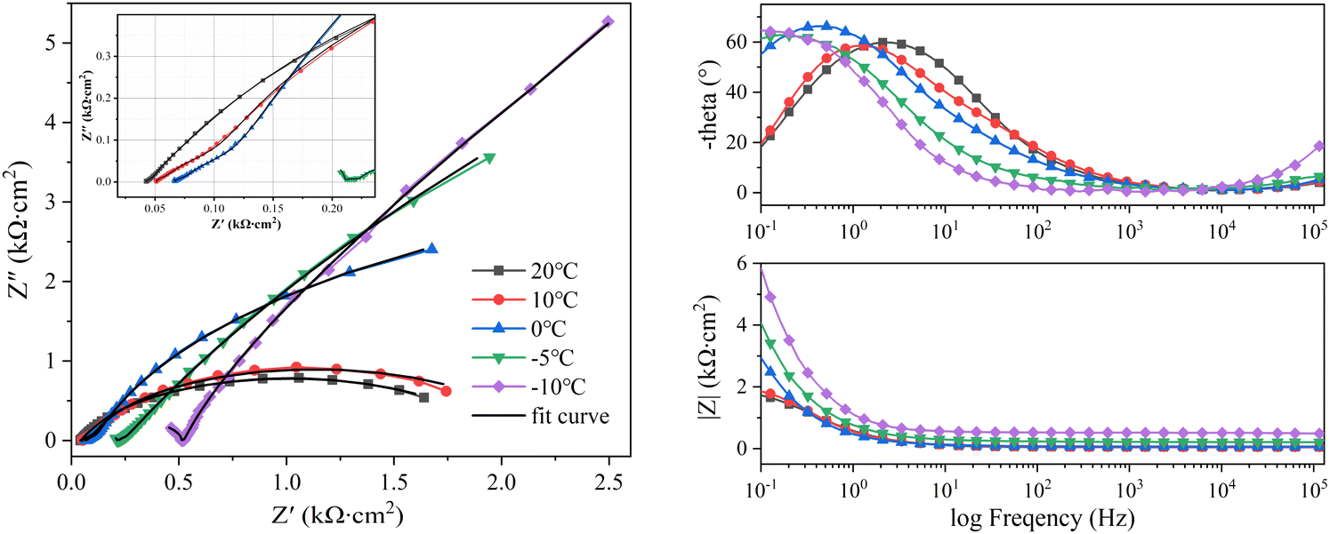 | ||
| Fig. 5 EIS curves of Q235 steel at different temperatures. (a) Nyquist curves. (b) Impedance phase-frequency curves. (c) Impedance modulus-frequency curves. | ||
Fig. 5b and6b show the impedance phase-frequency (IP-log![[thin space (1/6-em)]](https://www.rsc.org/images/entities/char_2009.gif) F) curves of the steel specimens. These IP-logF curves reflect the response process (relaxation process) of the corrosion system to disturbances. The relaxation constant τ = 1/ω* is commonly used to describe the speed of this process, where τ is the relaxation constant and ω* is the characteristic frequency of the sub-process when the relaxation occurs.23 Two time constants of the corrosion process were observed. The first time constant τ1 corresponded to the relaxation process of the rust-soil solution interface (high frequency), and the second time constant τ2 corresponded to the relaxation process of the rust-substrate interface (low frequency). And mass transfer process. The magnitude of τ2 directly reflects the total reaction rate of the electrode interface, and the magnitude of the total reaction rate reflects the corrosion rate. As the ambient temperature decreased, the IP-logF curves of the two steels shifted in the low-frequency direction, and this decrease in characteristic frequency led to an increase in the relaxation time constant. The increase in τ1 indicates that the dielectric capacity of the rust-soil solution interface was weakened, and the increase in τ2 indicates that the charge transfer and ion adsorption and diffusion in the rust-substrate interface were slowed down. The trend of the reaction rate at the interface was visualised by plotting the
F) curves of the steel specimens. These IP-logF curves reflect the response process (relaxation process) of the corrosion system to disturbances. The relaxation constant τ = 1/ω* is commonly used to describe the speed of this process, where τ is the relaxation constant and ω* is the characteristic frequency of the sub-process when the relaxation occurs.23 Two time constants of the corrosion process were observed. The first time constant τ1 corresponded to the relaxation process of the rust-soil solution interface (high frequency), and the second time constant τ2 corresponded to the relaxation process of the rust-substrate interface (low frequency). And mass transfer process. The magnitude of τ2 directly reflects the total reaction rate of the electrode interface, and the magnitude of the total reaction rate reflects the corrosion rate. As the ambient temperature decreased, the IP-logF curves of the two steels shifted in the low-frequency direction, and this decrease in characteristic frequency led to an increase in the relaxation time constant. The increase in τ1 indicates that the dielectric capacity of the rust-soil solution interface was weakened, and the increase in τ2 indicates that the charge transfer and ion adsorption and diffusion in the rust-substrate interface were slowed down. The trend of the reaction rate at the interface was visualised by plotting the  curves (Fig. 7). This demonstrated that the value of
  tended to slowly decrease with decreasing temperature, implying that the time required to complete the reaction at the electrode interface increased with decreasing temperature. Thus, the corrosion process slowed down.
 | ||
| Fig. 6 EIS curves of X80 steel at different temperatures. (a) Nyquist curves. (b) Impedance phase-frequency curves. (c) Impedance modulus-frequency curves. | ||
 | ||
| Fig. 7 Trend of the characteristic frequency of the second time constant with decreasing temperature. | ||
Fig. 5c and 6c show the impedance modulus-frequency (IM-logF) curves of the steel specimens. The IM-logF curves of the two steels shifted in the direction of increasing modulus with decreasing temperature across the whole frequency range. At the same time, the increase in impedance modulus accelerated as the frequency decreased, with a very large increase in the 10−1 to 101 Hz range.
The EIS curves at −5 °C and −10 °C were significantly different from those at other ambient temperatures. These temperatures achieved extremely large curvature radii in the low-frequency bands of their Nyquist curves, significantly larger phase values in the high-frequency bands of their IP-logF curves, and more drastic changes in the low-frequency bands of their IM-logF curves. Temperature changes affect the kinetic process and thermodynamic process of the irreversible electrode reactions in corrosion systems. The EIS curves were analysed by their equivalent circuits (ECs) to investigate the changes in the corrosion process.
The EC1 of the two different steels at 20, 10, 0, and −5 °C was (Cr-s(Rr-s(CpRp)(Cdl(Rr(CPERct))), and the EC2 at −10 °C was (Cr-sRr-s)(Cdl(Rr(CPE(RctW)))). The corrosion system and equivalent circuit are schematically shown in Fig. 8. Both EC1 and EC2 contained relaxation process of the two corrosion sub-processes, corresponding to the two time constants of the EIS. The Cr-s and Rr-s in EC distributions represent the capacitance and resistance of the rust-substrate interface. The Cp and Rp distributions represent the capacitance and resistance of pore solution. Cdl represents the electric double layer capacitance formed by the rust-substrate interface. Rr represent the resistance of the rust layer. The CPE electrode was used to represent the capacitance of the corrosion reaction zone due to the surface inhomogeneity of the solid electrode and the porous nature of the soil, which led to a dispersion effect. Rct represents the charge transfer resistance, and W represents the Warburg impedance. The black fitted EIS curves using the ECs are shown in Fig. 5 and 6. The fitted curves were in very good agreement with the EIS results, with high accuracy and a small fitting error.
 | ||
| Fig. 8 Schematic diagram of the corrosion architecture and equivalent circuits under different conditions. (a) At 20, 10, 0, and −5 °C. (b) At −10 °C. | ||
Fig. 9 shows the variation trends of the parameters related to the first time constant as the ambient temperature decreased from 20 °C to −5 °C. The value of the soil pore solution resistance RP gradually increased with decreasing temperature and sharply increased at −5 °C, which was related to the phase transition of the soil below 0 °C. The capacitance value of the pore solution Cp continually decreased during the cooling process, indicating that the charge flow was significantly inhibited. At the same time, low temperatures significantly inhibited ion activity, and the activity of ions in rust-soil solution interface was weakened. Thus, the rust-soil solution interface capacitance Cr-s continuously decreased with decreasing temperature and exhibited a sharp drop near 0 °C. The Rr-s value slightly fluctuated with decreasing temperature. When the temperature dropped to −10 °C, the Rr-s values of the Q235 and X80 steels were 511.9 Ω cm2 and 726.2 Ω cm2, respectively, indicating that the rust-soil solution interface had a high resistance value. This was because when the ambient temperature was lower than the freezing point, the solution content of the soil decreased, leading to rapidly increasing soil solution resistance. This was consistent with the increasing amplitude of the rightward shift in the high-frequency region of the Nyquist curves. The changes in the rust-soil solution interface indicate that the cooling process hindered the corrosion of steel.
 | ||
| Fig. 9 Trend of parameters related to the first time constant in EC1. | ||
Fig. 10 shows the variation trend of the parameters related to the second time constant as the ambient temperature decreased from 20 °C to −10 °C. The values of the double layer capacitances Cdl decreased with the decrease of temperature. It shows that the dielectric property of rust-substrate interface increased with decreasing temperature. The Rr associated with the rust layer fluctuated within a certain range with decreasing temperature, which was related to the repeated destruction of Cl−. The transition that occurred in the corrosion system had little effect on the resistance of the rust layer. The parameter n is used to represent the dielectric property of a component. When n = 0, CPE is equivalent to pure resistance, and when n = 1, CPE is equivalent to pure capacitance. Fig. 10 shows that the value of n decreased with decreasing temperature. This decline in dielectric ability meant that CPE showed stronger resistance properties. Rct characterises the difficulty of charge transfer and ion adsorption in a corrosion reaction zone, directly reflecting the dissolution and passivation behaviour of metal electrodes. The rapid increase in the Rct value as the temperature decreased was due to the gradually increasing ice phase content in the liquid film on the electrode surface in the reaction zone as the temperature decreased below the freezing point. This blocked electron and ion transport, resulting in a rapid increase in the diffusion impedance of the reaction zone, which was consistent with the phenomenon observed in the low-frequency region of the Nyquist curves. The value of Rct at 10 °C rapidly decreased, but at the same time, the Warburg impedance values for the Q235 and X80 steels were as high as 51167 Ω cm2 and 44294 Ω cm2, respectively. This demonstrated that the rate-controlling step of the corrosion reaction was transformed into the mass transfer process. During the cooling process of the corrosion system, the rate-controlling step of the corrosion reaction shifted from the joint charge transfer process and mass transfer process control to solely mass transfer process control.
 | ||
| Fig. 10 Trend of each parameter related to the second time constant in EC1 and EC2. | ||
3.3 Changes in the dielectric properties of soils
Declining temperature leads to thermodynamic changes in soil. The dielectric constant is used to characterise the dielectric properties and polarisation ability of soil, so it can be used to explain the changes that occur in soil with decreasing temperature. The factors affecting the dielectric constant of soil include soil properties, water content, electrolyte content, temperature, and test frequency.24–27 Both the complex impedance (Z*(ω)) and the complex permittivity (ε*(ω)) are alternative representations of the same relaxation process. The relationship between Z*(ω) and ε*(ω) can be expressed as 1/ε*(ω) = jωC0Z*(ω).28 The real part (ε′) and imaginary part (ε′′) of complex permittivity are calculated using eqn (1) and (2).| ε′ = 1/(ωC0) × Z′′/(Z′2 + Z′′2) | (1) |
| ε′′ = 1/(ωC0) × Z′/(Z′2 + Z′′2) | (2) |
Fig. 11 and 12 show the complex dielectric spectra of the steel corrosion systems at different temperatures. The real part of the complex dielectric constant is the dielectric constant (Fig. 11a and 12a), and the imaginary part is the dielectric loss (Fig. 11b and 12b). The dielectric properties of the soil were the dielectric properties of the solution in the soil. The water content of the solution and the type and quantity of dissociated ions were the main factors affecting the dielectric properties of this solution. This natural saline soil was internally complex, with many types of ions and a chaotic distribution. Thus, an uneven distribution of space charges was observed. Under an external electric field, soil polarisation exhibits inelastic polarisation characteristics—that is, relaxation polarisation.29 Relaxed polarisation leads to a longer polarisation time with energy loss, and is affected by both thermal motion disorder and electric field ordering. The relaxation polarisation in the soil consisted of ion relaxation polarisation and dipole relaxation polarisation. In addition, the soil was subject to space charge polarisation due to soil inhomogeneities. Therefore, the dielectric constants shown in Fig. 11 and 12 were the result of the superposition of multiple polarisation processes.
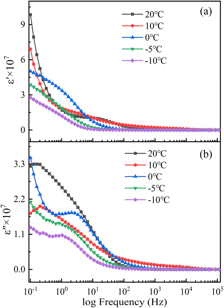 | ||
| Fig. 11 Dielectric spectra of Q235 steel corrosion systems during temperature reduction. | ||
The soil solution contained a large number of weakly bound ions. Under the action of an electric field, cations and anions respectively move backwards and forward along the electric field, leading to the generation of electric moments between the cations and anions and causing an uneven distribution of internal charges in soil. This process is known as ion relaxation polarisation. Water is the main component of the solution in soil. The molecular structure of water is V-shaped, leading to the existence of positive and negative charge centres that are very close together but do not overlap. This configuration is a typical dipole. Under the action of an external electric field, water molecules orient their dipoles along the direction of the electric field, a process known as dipole relaxation polarisation.30 Compared with ion relaxation polarisation, dipole relaxation polarisation is slower and exhibits higher polarisation intensity. However, both polarisation processes are affected by temperature and the presence of an electric field. Increasing the temperature aggravates the thermal motion of the system and increases the activity of ions and dipole moments. In a certain temperature range, the enhancement of thermal motion can promote the polarisation of ions and dipoles, but when the temperature is too high, the thermal motion of the system is very violent, making polarisation difficult. Therefore, under the action of a temperature contradiction mechanism, the ionic relaxation polarisation intensity and dipole relaxation polarisation intensity are maximised.
In addition, the accumulation of free charges due to soil inhomogeneity and the hindering effect of impurities such as soil particles causes the positive charges in soil to move toward the negative poles of the electric field and the negative charges to move toward the positive poles of the electric field. This occurs under the action of the electric field, resulting in space charge polarisation. Temperature has a significant effect on the thermal movement of charges, with increasing temperature leading to a decrease in the intensity of space charge polarisation. Therefore, space charge polarisation occurs less frequently than relaxation polarisation due to the long time required for the space charge to accumulate. These polarisation processes are difficult to complete at high frequencies, so the dielectric constant therefore decreases and stabilises with increasing frequency.
The intensity of the polarisation established by ion relaxation was reflected in the 101 to 102 Hz frequency range of the dielectric constant. As the temperature decreased, the thermal motion of the ions weakened, and the time required to complete the polarisation increased. Thus, the polarisation frequency shifted toward lower frequencies. At the same time, the polarisation intensity decreased with decreasing temperature due to the lower thermal motion of ions. This meant that the ion activity was insufficient, making polarisation difficult. Moreover, when the temperature dropped below the freezing point, the viscosity of the solution increased and ion polarisation was more difficult to carry out.31 The completion time of dipole relaxation polarisation was slightly longer, and the response of high-intensity dipole polarisation to frequency was concentrated in the dielectric constant frequency range of 10−1 to 100 Hz. The maximum values of the dipole polarisation intensity in the soils where the two steels were located were achieved at different temperatures. This was influenced by the complexity and inhomogeneity of the natural saline soil. The influence of temperature on dipole polarisation was mainly due to the influence of temperature on the water molecules.32 The hydrogen bonding between the water molecules gradually increased with decreasing temperature, which weakened the thermal motion of water molecules. When the temperature was lower than the freezing point, hydrogen bonding bound the movement of water molecules, making them aligned and causing the water to freeze into ice. Frozen water molecules do not easily respond to electric field polarisation. The natural soil was complex and uneven, so when the temperature was low enough to cause a phase change in the soil, the change law of dipole polarisation intensity was more significant. Because of its characteristics, space charge polarisation only appeared at low frequencies, and because its intensity was not high, its characteristics were masked by relaxation polarisation.
Both relaxation polarisation and space charge polarisation are inelastic polarisation processes that lead to dielectric loss. A large number of studies have shown that the dielectric loss of soil is mainly caused by electrical conductivity. Electrical conductivity is affected by both water content and salt content. Fig. 12 shows that the change in the soil dielectric loss with temperature was not obvious when the temperature was higher than 0 °C. This was because the changes in the water content and salt content were not clear. When the temperature dropped below the freezing point, the soil-connected pores froze, the free water content decreased, and the conductive pathways in the soil sharply decreased. At the same time, the ionic activity in the solution was very low, and charge transfer in the solution was blocked. The dielectric constant and dielectric loss of the soil below the freezing point were related to the content of unfrozen water in the soil.
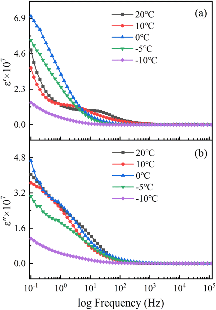 | ||
| Fig. 12 Dielectric spectra of X80 steel corrosion systems during temperature reduction. | ||
The changes in the dielectric constant and dielectric loss of the soil demonstrate that the temperature affected the dielectric properties of the soil by changing the thermal motion of water molecules and ions and by controlling the phase transition of the soil. The corrosion of steel in soil mainly depends on the charge transfer and diffusion mass transfer of the soil solution. The activity of the corrosion system and the phase change of the water directly affect the charge transfer and diffusive mass transfer processes in soil and are the main factors inhibiting steel corrosion at low temperatures.
3.4 Polarisation curve analysis
Fig. 13 and 14 show the polarisation curves of Q235 steel and X80 steel at various temperatures during the cooling process. The cathodic polarisation curves represent the reduction process of the depolariser (O2). The cathodic curves for both steels shifted toward higher current densities as the temperature decreased from 20 °C to 0 °C, indicating that the reduction rate of O2 accelerated. This was potentially caused by the increasing oxygen solubility with decreasing temperature.31 Studies have shown that in salt solutions, the solubility of oxygen at 0 °C is almost 1.5 times that at 20 °C.33 Oxygen diffused to the electrode surface by dissolving in the solution, so the increase in oxygen solubility accelerated the cathodic reduction reaction. However, when the temperature decreased from 0 °C to −10 °C, the ice phase gradually precipitated from the solution, hindering the exchange of gas between the corrosion reaction zone and the soil. At the same time, the number of soil-connected pores was reduced and the diffusion path of oxygen in the soil was blocked, so the cathode curve shifted in the direction of lower current density.34 The anodic polarisation of the two steels showed obvious activation–passivation behaviour. With decreasing temperature, anodic metal dissolution was inhibited, the passivation potential decreased, and the passivation interval widened. Low temperatures inhibited the thermal movement of electrons and ions in the system, hindered charge transfer and ion adsorption, and slowed the rate of metal dissolution. At lower temperatures, steel is more prone to passivation, and the passivation state tends to be stable. During the cooling process, the amplitude of the suppression of the anode curve was consistent with the amplitude of the impedance increase in the low-frequency band of EIS, and the EIS results were in good agreement with the PC results.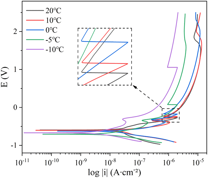 | ||
| Fig. 13 Polarisation curves of Q235 steel during temperature reduction. | ||
 | ||
| Fig. 14 Polarisation curves of X80 steel during temperature reduction. | ||
The kinetic parameters Ecorr and Icorr related to the corrosion process were obtained by fitting the polarisation curve using the Tafel method. Ecorr and Icorr were used to characterise the corrosion tendency and the rate of the corrosion reaction, respectively. The value of Icorr can be calculated by using the Stern–Geary equation (eqn (3))
 | (3) |
| Q235 | X80 | |||||
|---|---|---|---|---|---|---|
| T (°C) | ba | bc | B | ba | bc | B |
| 20 | 101.54 | 182.2 | 28.31 | 95.37 | 77.45 | 18.56 |
| 10 | 107.69 | 172.34 | 28.78 | 101.45 | 74.26 | 18.62 |
| 0 | 116.13 | 219.39 | 32.97 | 125.31 | 91.24 | 22.93 |
| −5 | 165.47 | 111.96 | 29.00 | 140.85 | 102.04 | 25.69 |
| −10 | 238.89 | 158.55 | 41.38 | 205.41 | 131.62 | 34.83 |
The variation of the Tafel slope can reflect the degree of metal polarization. The ba values of Q235 steel and X80 steel gradually increased with the increase of temperature, indicating that the soil cooling process would significantly slow down the dissolution rate of metal, and the corrosion reaction would be more difficult to occur. Cathodic Tafel slope bc value gradually increased with temperature decrease is associated with an increased dissolved oxygen content in the process. The rapid decrease of bc value of Q235 steel at −5 °C was affected by solution freezing. The same temperature, the Q235 steel Stern–Geary coefficient B above X80 steel shows that under the same environment of X80 steel more resistant to corrosion.
The corrosion rate of the electrode was calculated by eqn (4).
 | (4) |
The trends of Ecorr, Icorr, and CR during the cooling process are exhibited in Fig. 15. According to Fig. 15, the corrosion rates of the Q235 and X80 steels slowed down with decreasing temperature. Ecorr continuously decreased in the range of 20–5 °C, which was related to the increase of adsorbed OH− ions caused by the increase in the oxygen solubility of the soil. The value of Ecorr increased at −10 °C, and phase transformation occurred at the electrode interface at −10 °C. Thus, with decreasing temperature, the unfrozen water content decreased, the dissolved oxygen content in the solution decreased, diffusion was slowed down, and the corrosion process was difficult to carry out.
 | ||
| Fig. 15 Trends in polarisation curve kinetic parameters with temperature. | ||
3.5 Changes in soil thermodynamics during cooling
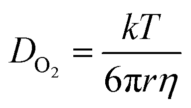
According to the results of the electrochemical tests, the corrosion behaviour of the steels in the saline soils was inhibited during the cooling process. However, the inhibition behaviour changed during testing, clearly demonstrating that the mechanism of this inhibition behaviour was related to temperature. Using the freezing point as a cut-off, the changes in corrosion inhibition above and below the freezing point were analysed.In soil, steel corrosion occurs due to oxygen absorption corrosion. The oxygen is reduced as a depolarising agent in the cathodic corrosion reaction (eqn (5)). Oxygen mainly participates in the reaction by dissolving in the pore solution and diffusing into the liquid film on the electrode surface. The solubility of oxygen is extremely dependent on the temperature. Oxygen solubility increases with decreasing temperature.31 In salt solutions, the difference in the solubility of oxygen at 20 °C and 0 °C can reach up to 50%.33 Furthermore, the temperature dependence of the diffusion coefficient of oxygen in solution is described by the Stokes–Einstein equation:36 (eqn (6)):
| 1/2O2 + H2O + 2e− → 2OH− | (5) |
 | (6) |
|
lnk(T) = lnA − Ea/RT
| (7) |
The charge density of the electric double layer significantly influenced ion transport.37 This charge density was very sensitive to temperature. With decreasing temperature, the charge density decreased. This weakened the adsorption capacity of the electrode surface for OH −, which reduced the reaction rate of ferrous ions with OH− to generate ferrous hydroxide (eqn (8)). Thus, the anodic dissolution of iron was slowed down. The slowing trend of anodic dissolution was observed via the Rct values (Fig. 10) and anodic polarisation curves (Fig. 13 and 14) at 20, 10, and 0 °C. In addition, the Cl− in the soil significantly damaged the passivation film on the electrode surface,38,39 but as the charge density of the electric double layer decreased, the ability of the electrode surface to adsorb Cl− was weakened. This reduced the passivation potential of the electrode surface, and the passivation region widened.
| Fe2+ + 2OH− → Fe(OH)2(s) | (8) |
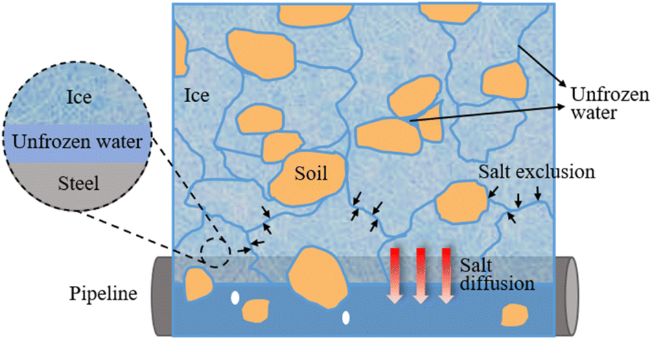 | ||
| Fig. 16 Structure of corrosion system in a frozen state. | ||
The EIS curves (Fig. 5 and 6) and polarisation curves (Fig. 13 and 14) of the two steels at −5 °C and −10 °C show that the corrosion reaction was controlled by the mass transfer process. The reactants and products always diffused from areas of high concentration to areas of low concentration. Due to the existence of the ice phase, a diffusion barrier layer was formed on the electrode surface, and the diffusion of oxygen and the migration of metal cations were blocked. The control of the corrosion reaction rate by the mass transfer process was gradually strengthened as the temperature decreased, with mass transfer eventually becoming the rate-controlling step of the corrosion reaction.
It is important to be alert to the potential soil corrosion hazard caused by ion migration during the freezing and thawing process in seasonal frozen soil areas.50 During solution freezing, as ice crystals grow, large amounts of ions are expelled from these ice crystals, which enriches the area around the ice crystals and increases the salt content of unfrozen water in the frozen area.51 At the same time, intercrystalline channels with high conductivity and low freezing points are formed between the ice crystals. Due to the high concentration difference, salt diffuses into the unfrozen area.52 During freezing, salt in the soil is transported from the frozen zone to the unfrozen zone where buried underground pipes and facilities are located. This is a major challenge affecting the long-term corrosion resistance of underground facilities53 and significantly shortens their service life.
Conclusions
In this study, Q235 and X80 steels were used as the research objects to systematically analyse the corrosion behaviour of carbon steel in the cooling process of saline soil by electrochemical testing (EIS). By analysing the corrosion kinetic parameters and thermodynamic changes in the corrosion system, the following conclusions were obtained:When the ambient temperature dropped, the relaxation time constant of the electrochemical reaction of carbon steel in saline soil significantly increased, the time to complete the relaxation process increased, and the corrosion reaction slowed down. Carbon steel in the temperature range of −5 to 20 °C exhibited the equivalent circuit of (Cr-s(Rr-s(CpRp)))(Cdl(Rr(CPERct))), with the exception of −10 °C, where the equivalent circuit was (Cr-sRr-s)(Cdl(Rr(CPE(RctW)))). The rate-controlling step of the carbon steel corrosion reaction shifted from a charge transfer and mass transfer process to a mass transfer process.
The complex permittivity of the saline soil at different temperatures was calculated by EIS. Under the action of the electric field, the soil polarisation included relaxation polarisation and space charge polarisation. The change in the soil pore solution with temperature was the main factor affecting the dielectric capacity and polarisation intensity of the soil.
The polarisation curves show that the kinetic parameters related to corrosion were all suppressed during the cooling process. The anodic reaction was mainly affected by the water activity, the thermal motion of ions, and the unfrozen water content. The cathodic reaction was mainly affected by oxygen dissolution diffusion and pore connectivity.
The soil phase transition affected the mechanism of corrosion inhibition. When the solution was not frozen, temperature affected the corrosion process by changing the thermal motion of water, ions, and electrons in the solution as well as the concentration of dissolved oxygen. After the solution began to freeze, the unfrozen water content became the main influencing factor.
Conflicts of interest
There are no conflicts to declare.Acknowledgements
This work was supported by the National Natural Science Foundation of China (No. 41807256), the Applied Basic Research Program in Shanxi Province (No. 20210302123139).References
- Z. Xiao, Y. Lai and M. Zhang, Acta Geotech., 2018, 13, 195–205 CrossRef.
- H. Bing and W. Ma, Cold Reg. Sci. Technol., 2011, 67, 79–88 CrossRef.
- J. Zhou, X. Meng, C. Wei and W. Pei, Water Resour. Res., 2020, 56, e2019WR026648 Search PubMed.
- Z. Xiao, L. Zhu and Z. Hou, Geoderma, 2022, 419, 115881 CrossRef CAS.
- X. Wan and Z. J. Yang, Cold Reg. Sci. Technol., 2020, 173, 103030 CrossRef.
- Z. Xiao, Y. Lai and J. Zhang, Cold Reg. Sci. Technol., 2020, 172, 103011 CrossRef.
- X. Wan, E. Liu, E. Qiu, M. Qu, X. Zhao and F. Nkiegaing, Cold Reg. Sci. Technol., 2020, 172, 102988 CrossRef.
- X. Wan, Q. Hu and M. Liao, Cold Reg. Sci. Technol., 2017, 137, 36–47 CrossRef.
- Y. Lai, D. Wu and M. Zhang, Appl. Therm. Eng., 2017, 120, 463–473 CrossRef.
- Z. Xiao, Y. Lai, Z. You and M. Zhang, Arabian J. Sci. Eng., 2017, 42, 3923–3932 CrossRef CAS.
- S. Zhang, J. Zhang, Y. Gui, W. Chen and Z. Dai, Cold Reg. Sci. Technol., 2020, 177, 103121 CrossRef.
- J. Zhang, Y. Lai, Y. Zhao and S. Li, Permafr. Periglac. Process., 2021, 32, 102–118 CrossRef.
- X. Zhang, S. Liu, Q. Wang, G. Wang, Y. Liu, W. Peng, X. Xu and Y. Liu, Pol. J. Environ. Stud., 2019, 28, 1495–1505 CrossRef.
- M. Wang, Y. Zhu, T. Zhao, L. Cui, W. Mao, M. Ye, J. Wu and J. Yang, J. Hydrol., 2022, 606, 127403 CrossRef CAS.
- J. Liu, P. Yang and Z. J. Yang, Cold Reg. Sci. Technol., 2020, 178, 103127 CrossRef.
- N. Tashpolat, J. Ding and D. Yu, J. Arid Land, 2015, 7, 696–705 CrossRef.
- S. Yun, G. Huadong, H. Qingrong, L. Yuan, D. Qing and H. Chunming, Study on complex dielectric properties of saline soils, 2002 Search PubMed.
- Z. F. Yin, Y. Feng, W. Zhao, Z. Bai and G. Lin, Surf. Interface Anal., 2009, 41, 517–523 CrossRef CAS.
- R. Melchers, Corrosion, 2002, 58, 09 CrossRef.
- A. Benmoussat and M. Hadjel, Eurasian Chem.-Technol. J., 2005, 7, 147–156 CrossRef CAS.
- X. Bai, B. He, P. Han, R. Xie, F. Sun, Z. Chen, Y. Wang and X. Liu, RSC Adv., 2022, 12, 129–147 RSC.
- F. Sun, X. Peng, X. Bai, Z. Chen, R. Xie, B. He and P. Han, RSC Adv., 2022, 12, 16979–16990 RSC.
- D. Clematis, T. Ferrari, A. Bertei, A. M. Asensio, M. P. Carpanese, C. Nicolella and A. Barbucci, Electrochim. Acta, 2021, 391, 138916 CrossRef CAS.
- S. Y. Wu, Q. Y. Zhou, G. Wang, L. Yang and C. P. Ling, Environ. Earth Sci., 2011, 62, 999–1011 CrossRef CAS.
- V. Mironov, A. Y. Karavayskiy, Y. I. Lukin and I. Molostov, Int. J. Remote Sens., 2020, 41, 3845–3865 CrossRef.
- X. Xu, W. Zhang and Y. Wang, Acta Geotechnica, 2022, 1–20 Search PubMed.
- K. Sreenivas, L. VENKATARATNAM and P. N. Rao, International Journal of Remote Sensing, 1995, 16, 641–649 CrossRef.
- J. Swiergiel and J. Jadzyn, Ind. Eng. Chem. Res., 2011, 50, 11935–11941 CrossRef CAS.
- F. Pabst, Z. Wojnarowska, M. Paluch and T. Blochowicz, Phys. Chem. Chem. Phys., 2021, 23, 14260–14275 RSC.
- W. Gan, D. Wu, Z. Zhang, R.-r. Feng and H.-f. Wang, J. Chem. Phys., 2006, 124, 114705 CrossRef.
- W. Xing, M. Yin, Q. Lv, Y. Hu, C. Liu and J. Zhang, in Rotating electrode methods and oxygen reduction electrocatalysts, Elsevier, 2014, pp. 1–31 Search PubMed.
- R. Buchner, J. Barthel and J. Stauber, Chem. Phys. Lett., 1999, 306, 57–63 CrossRef.
- G. Ming and D. Zhenhao, Geochim. Cosmochim. Acta, 2010, 74, 5631–5640 CrossRef.
- J. Neira, M. Ortiz, L. Morales and E. Acevedo, Chil. J. Agric. Res., 2015, 75, 35–44 CrossRef.
- Y. Z. Su, Y. C. Fu, Y. M. Wei, J. W. Yan and B. W. Mao, ChemPhysChem, 2010, 11, 2764–2778 CrossRef CAS PubMed.
- C. C. Miller, Proc. R. Soc. London, Ser. A, 1924, 106, 724–749 CAS.
- D. Stein, M. Kruithof and C. Dekker, Phys. Rev. Lett., 2004, 93, 035901 CrossRef PubMed.
- Y. Ma, Y. Li and F. Wang, Corros. Sci., 2009, 51, 997–1006 CrossRef CAS.
- M. Yang and S. Kainuma, Corros. Eng., Sci. Technol., 2021, 56, 690–702 CrossRef CAS.
- H. Tian, C. Wei, H. Wei and J. Zhou, Cold Reg. Sci. Technol., 2014, 103, 74–81 CrossRef.
- Z. Sun and G. W. Scherer, Cem. Concr. Res., 2010, 40, 740–751 CrossRef CAS.
- J. Cary and H. Mayland, Soil Sci. Soc. Am. J., 1972, 36, 549–555 CrossRef CAS.
- P. J. Williams, Geotechnique, 1964, 14, 231–246 CrossRef.
- X. Jin, W. Yang, X. Gao, J. Q. Zhao, Z. Li and J. Jiang, Water Resour. Res., 2020, 56, e2020WR027482 CrossRef.
- L. Daikhin and V. Tsionsky, J. Phys.: Condens. Matter, 2007, 19, 376109 CrossRef.
- J. Dash, Contemp. Phys., 2002, 43, 427–436 CrossRef CAS.
- V. Tsionsky, E. Alengoz, L. Daikhin, A. Kaverin, D. Zagidulin and E. Gileadi, Electrochim. Acta, 2005, 50, 4212–4221 CrossRef CAS.
- A. Kaverin, V. Tsionsky, D. Zagidulin, L. Daikhin, E. Alengoz and E. Gileadi, J. Phys. Chem. B, 2004, 108, 8759–8762 CrossRef CAS.
- V. Tsionsky, L. Daikhin, D. Zagidulin, M. Urbakh and E. Gileadi, J. Phys. Chem. B, 2003, 107, 12485–12491 CrossRef CAS.
- X. Zhang, Q. Wang, G. Wang, W. Wang, H. Chen and Z. Zhang, Mathematical Problems in Engineering, 2017 Search PubMed.
- L. Vrbka and P. Jungwirth, Phys. Rev. Lett., 2005, 95, 148501 CrossRef.
- J. Liu, P. Yang and Z. J. Yang, Cold Reg. Sci. Technol., 2021, 186, 103277 CrossRef.
- Y. Lan, H. Chang, G. Qi, P. Han and B. He, Int. J. Electrochem. Sci., 2021, 16, 9 Search PubMed.
| This journal is © The Royal Society of Chemistry 2022 |