DOI:
10.1039/D2RA04544C
(Paper)
RSC Adv., 2022,
12, 27641-27647
Comparison of water desalination performance of porous graphene and MoS2 nanosheets†
Received
22nd July 2022
, Accepted 21st September 2022
First published on 28th September 2022
Abstract
Following graphene and its derivatives, molybdenum disulfide (MoS2) has become a research hotspot in two-dimensional materials. Both graphene and MoS2 exhibit great potential in water treatment. A variety of nanoporous graphene or MoS2 membranes have been designed for water desalination. In this work, we compared the water flux and ion rejection of MoS2 and graphene nanopores, using molecular dynamics simulations. The simulation results demonstrate that monolayer nanopores have higher water fluxes than bilayer nanopores with lower ion rejection rates. MoS2 nanopores perform better than graphene in terms of water permeability. Exploration of the underlying mechanism indicates that the water molecules in the MoS2 pores have faster velocity and higher mass density than those in the graphene pores, due to the outer hydrophobic and inner hydrophilic edges of MoS2 pores. In addition, increasing the polarity of the pore edge causes a decrease in water flux while enhancement of ion rejection. Our findings may provide theoretical guidance for the design of MoS2 membranes in water purification.
1. Introduction
In recent years, two-dimensional (2D) materials have received extensive interest due to their outstanding electronic, mechanical and optical properties, and have exhibited great potential in various fields, such as supercapacitors, photocatalysis and biosensors.1–3 Another important application is in water treatment, since laminar 2D materials can be stacked into membranes as filters, or nanopores drilled on 2D materials allow water transport while reject the passage of ions.4–8 Compared with conventional reverse osmosis (RO) membranes, which suffer from weak water permeation and high energy consumption, the filter membranes prepared from 2D materials often possess better desalination performance, including high water permeation, high ion rejection and cost-effectiveness.9
One kind of typical 2D material is graphene and its derivatives that have shown increasing potential in water desalination.10–15 For example, Suk et al. first designed nanoporous graphene to transport water molecules via molecular dynamics (MD) simulations. They found that the water flux of graphene membrane was higher than that of carbon nanotube for larger diameter pores.16 Similarly, Cohen-Tanugi et al. introduced nanopores into graphene to filter salts. They studied the effects of pore size, edge modification and exerted pressure on the desalination performance of this freestanding graphene membrane using MD simulations.17 Their results indicated that the water flux of the nanoporous graphene is 3–4 orders of magnitude higher than commercial RO membranes. Furthermore, graphene can be oxidized into graphene oxide (GO). And GO suspension can be formed into membranes through drop-casting or vacuum filtration, and so on.10,18 The low cost and easy preparation of GO films have attracted much attention and have been extensively studied. GO membranes possess high water permeation and excellent ion rejection.19–21 The unoxidized regions of the GO nanosheets provide an almost frictionless surface for the flow of water with high water permeability.22–24 However, their use is limited by the swelling effect in aqueous solutions,25 and the transport of water is low due to side-pinning effect between water and functional groups on the GO surface.26–28 One method employed to inhibit swelling effect is reduction that GO is reduced to a certain extent to weaken its hydrophilicity. Another strategy to alleviate swelling effect is crosslinking.29,30 For example, Huang et al. prepared a reduced GO (rGO) membrane that has low ion permeation and ideal water flux.31 After GO sheets were crosslinked by urea, the performance of GO membranes was greatly improved that the rejection rates for MgSO4 and CuSO4 rose to 73.5% and 81.9%, respectively. In addition, low water permeation may be caused because of the distinct decrease in the interlayer spacing of GO membranes after reduction.32
As a newly developed 2D material, molybdenum disulfide (MoS2) has attracted growing attention since its potential application in water treatment.33–39 Li et al. prepared MoS2 membranes with a thickness of ∼7 nm for water desalination using chemical vapor deposition. These membranes owned both high water permeability (>322 L m−2 h−1 bar−1) and high ion rejection capacity for Na+, K+, Ca2+, and Mg2+ (>99%).35 These prominent desalination performances are attributed to the intrinsic atomic vacancies between MoS2 layers. Another method to fabricate few-layer MoS2 is liquid-phase exfoliation. The obtained MoS2 thin film nanocomposite showed an optimal water permeability of 6.2 L m−2 h−1 bar−1 and salt rejection of 98.6% for NaCl.36 Theoretically, Li et al. developed a tunable nanopore on a MoS2 nanosheet using MD simulations. By applying lateral strain, the nanopore can exhibit the “open” state allowing water transportation and impeding ion flow and “closed” state that both water and ions cannot pass through the pore.18 Heiranian et al. performed MD simulations to investigate the water desalination performance of MoS2 nanopores. The pore areas fell in the range of 20–60 Å2. They constructed three kinds of MoS2 nanopores, namely, Mo atoms only, S atoms only and mixed Mo, S atoms on the pore edge. They found that Mo only pore has the highest rate of water permeation, because Mo only pore is much hydrophilic.37 Using MD simulations, Kou et al. constructed a nanoporous MoS2 monolayer with different pore diameters ranging from 5.3 Å to 13.5 Å. They demonstrated that a nanoporous MoS2 membrane with a pore diameter of 7.4 Å possesses both high water permeability and perfect salt rejection. The fast movement of water molecules across the monolayer MoS2 nanopore was attributed to the single-chain hydrogen bonds linking the water molecules inside and outside the nanopores.38 Similarly, Azamat et al. designed four MoS2 nanopores with different areas (9.306–37.345 Å2) to filter heavy metal ions. They suggested that the most appropriate pore area for complete heavy metal rejection along with high water permeability is 22.423 Å2.39
Although both graphene and MoS2 monolayers possess excellent water desalination performance and theoretical studies show that MoS2 is better than graphene,40 the comparison of desalination performance of these membranes needs further confirmation. On the other hand, multilayer membranes are more feasible and reasonable than monolayer membranes in practical applications. In this work, we used MD simulations to investigate the water desalination performance of MoS2 and graphene nanopores in monolayer and bilayer membranes. Through varying the pore area, we determine an ideal pore size with high water permeation and reasonable ion rejection. Then, we compare the desalination performance of graphene and MoS2 nanopores under the applied pressures from 100 MPa to 300 MPa. And the fundamental mechanism is explored based on the analysis of water density and velocity in the pores.
2. Methods
Fig. 1(a) shows the configuration of an individual simulation system, which consists of four parts from left to right: a graphene piston, 1 mol L−1 NaCl solution, a free-standing membrane with a nanopore and fresh water. The size of simulation box is 4 nm × 4 nm × 13 nm. The membranes used in the simulations were established by visual molecular dynamics (VMD) and Materials Studio (MS).41 We constructed four types of membranes, namely, MoS2 monolayer, MoS2 bilayer, graphene (GE) monolayer and graphene bilayer, which are denoted as MoS2, BiMoS2, GE and BiGE, respectively (Fig. 1(b)). The atoms at the center of the nanosheets were removed to obtain four pore sizes (47 Å2, 56 Å2, 64 Å2 and 72 Å2).
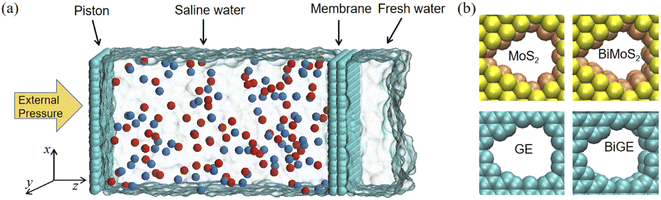 |
| | Fig. 1 (a) Side view of an individual simulation system, composed of a piston, a membrane with a nanopore and two water boxes. The left water box is saline while the right one is fresh water. (b) Atomic structures of four nanopores. Color scheme: Mo yellow, S brown, C cyan, Na+ red and Cl− blue. | |
All MD simulations were carried out by LAMMPS software.42 Water molecules were realized by the SPC/E model.43 The bonds and angles of water molecules were constrained by the SHAKE algorithm with the accuracy tolerance of 0.0001. The atomic interactions were calculated using the Lennard–Jones (LJ) potential as well as long-range Coulomb interactions. The LJ parameters of all atoms in the simulations were recorded in the ESI (see Table S1†). Arithmetic mix rule was adopted for interactions between different atoms. The cutoff radius of both LJ potential and Coulomb interaction was 12 Å. The long-range Coulomb interaction was computed by the particle–particle particle–mesh (PPPM) solver,44 and the relative root mean square error was 0.005.
Each independent simulation consists of three steps: minimization, NPT ensemble relaxation, and NVT ensemble product simulation. First, 10![[thin space (1/6-em)]](https://www.rsc.org/images/entities/char_2009.gif) 000 steps of iteration were performed to minimize the energy. Then, the NPT ensemble relaxation process was conducted for 100 ps with a time step of 1 fs. The temperature was kept stable at 300 K and the pressure was controlled anisotropically at 1 bar by the Nosé–Hoover thermostat and barostat, respectively.45,46 During equilibrium, the atoms of graphene and MoS2 remained fixed, and the NPT process enabled water to reach the equilibrium density of water (1 g cm−3). Finally, the production run in NVT ensemble was carried out for 10 ns at 300 K with a time step of 2 fs. The external pressure was achieved by exerting forces on each atom of the piston. The force (f) was determined by the following formula:
000 steps of iteration were performed to minimize the energy. Then, the NPT ensemble relaxation process was conducted for 100 ps with a time step of 1 fs. The temperature was kept stable at 300 K and the pressure was controlled anisotropically at 1 bar by the Nosé–Hoover thermostat and barostat, respectively.45,46 During equilibrium, the atoms of graphene and MoS2 remained fixed, and the NPT process enabled water to reach the equilibrium density of water (1 g cm−3). Finally, the production run in NVT ensemble was carried out for 10 ns at 300 K with a time step of 2 fs. The external pressure was achieved by exerting forces on each atom of the piston. The force (f) was determined by the following formula:
where
p is external pressure and
S is the area of piston and
N is the number of atoms of the piston.
3. Results and discussion
3.1. Adsorption performance of graphene and MoS2 nanosheets
Ahead of investigating water desalination through porous graphene and MoS2 nanosheets, we should compare the adsorption features of water molecules on graphene and MoS2 surface. Therefore, we first performed simulations of water with GE or MoS2 monolayer or bilayer (see Fig. 2(a) and (b)). Fig. 2(c) shows the mass density of water on the four membranes. Similar to our previous study, we find that there are two adsorbed layers on membrane surface.47 The first peaks of GE and BiGE are located at the same position (z = 0.40 Å), close to the vdW radius of carbon atom. The corresponding mass density at this distance is 3.23 g cm−3 and 3.85 g cm−3. Obviously, the mass density of water on BiGE is slightly higher than on GE. This is because the second GE monolayer enhances the adsorption. As comparison, the first peaks of MoS2 and BiMoS2 exhibit much lower than those of GE and BiGE, which is attributed to the atomic structure of MoS2. Interestingly, it is found that both peaks of MoS2 and BiMoS2 are completely overlapped (∼2.46 g cm−3). That is, the adsorption capacities of MoS2 and BiMoS2 are almost identical. The thicknesses of MoS2 monolayer and bilayer are approximately 6.2 Å and 12.4 Å,48 therefore, the interactions between water molecules and the second MoS2 layer are almost negligible, as the distance between water molecules and the second MoS2 layer is approximate 10 Å, which is close to the cutoff of vdW interactions. This indicates that the graphene surface is more hydrophilic than MoS2 (S site).29 Correspondingly, water molecules in the first adsorbed layer are thermodynamically stable, especially on GE surface.
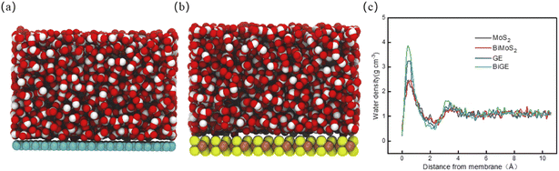 |
| | Fig. 2 (a) Snapshot of water on GE surface. (b) Snapshot of water on MoS2 surface. (c) Mass density profiles of water molecules with the distance from nanosheets. | |
3.2. Determining the optimal pore size of the four membranes
In general, water flux is directly proportional to pore size, while ion rejection is inversely proportional to pore size.49 Therefore, we should make a compromise between water flux and ion rejection. In detail, we should try to improve the water permeability as well as acceptable ion rejection. We varied the pore area from 47 Å2 to 72 Å2 to find a reasonable pore size for this purpose. Fig. 3 presents the water desalination performance of the four membranes with different pore area at external pressure of 150 MPa. It is found that the intersection points between water flux and ion rejection are close with each other at ∼62 Å2 in all four cases. Since pore area is not continuous but discrete with the number of removed atoms, we conclude that the pore area at 64 Å2 is an optimal size suitable to water desalination. At this point, the four membranes achieve a reasonable balance between water permeation and ion rejection. The water fluxes are 96.67 ns−1, 78.37 ns−1, 71.43 ns−1, 65.93 ns−1, and the rejection rates are 94.41%, 98.33%, 95.53%, 98.23% for MoS2, BiMoS2, GE, BiGE, respectively. The water desalination performance of the four membranes with different pore area at external pressure of 200 MPa holds the similar trend (see ESI, Fig. S1†). In the following comparison of desalination performance of the four membranes, pore area is fixed at this value (64 Å2).
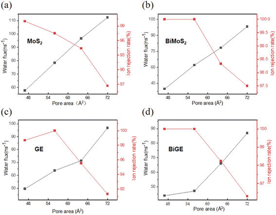 |
| | Fig. 3 Water flux and ion rejection against pore size of four membranes. (a) MoS2 monolayer, (b) MoS2 bilayer, (c) GE monolayer, (d) GE bilayer. | |
3.3. Comparing the water flux and ion rejection of the four membranes
As shown in Fig. 4(a), the water flux ratchets up gradually with the increasing pressure. MoS2 pore has the highest water flux followed by BiMoS2, GE and BiGE for all the applied pressures from 100 MPa to 300 MPa. On the other hand, the monolayer provides a higher flux than bilayer. For example, the water fluxes of MoS2 and BiMoS2 are 96.67 ns−1 and 78.36 ns−1 at the external pressure of 150 MPa (see ESI, Fig. S2(e)†). Particularly, MoS2 nanopores own higher water permeance than GE nanopores regardless of monolayer or bilayer. For example, the water flux of MoS2 nanopore is approximate 96.67 ns−1, while this flux decline to 71.43 ns−1 for GE nanopore (Fig. S2(e)†) at 150 MPa. MoS2 monolayer and bilayer perform 35.4% and 18.9% better than its GE counterparts at this external pressure. The water flux of MoS2 and GE under other pressures presents the similar results (see ESI, Fig. S2†). Another important parameter in water desalination is ion rejection rate, which indicates the capacity of the membrane to filter ions. Fig. 4(b) presents the percentage of ions blocked by the four nanopores. In general, the ion rejection decreases with the increasing pressures as high pressures exert higher forces on the ions leading to more ions passing the pores. For example, the ion rejection of MoS2 nanopore declines from 95.43% to 70.36% with the pressure increasing from 100 MPa to 300 MPa. Contrary to the water flux, monolayer has a lower ion rejection than bilayer. Taking MoS2 and BiMoS2 at 100 MPa as an example, the rejection rate of MoS2 is 95.43%, while that of BiMoS2 reaches highly 99.13%. This is because bilayer membranes increase the length of the channel, thereby enhancing the resistance of ions to pass through. Unfortunately, MoS2 nanopore exhibits the lowest ion rejection at the same pressure, especially at higher pressure. Fig. S2(f)† shows the number of ions passing the pore as a function of simulation time. During the 10 ns simulation, approximate 7, 2, 5 and 2 Na+ ions go through the MoS2 BiMoS2, GE and BiGE pores, respectively. Although MoS2 nanopore has high ion permeation, the rejection rates at pressure <150 MPa are still higher than 95%.
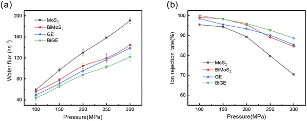 |
| | Fig. 4 (a) Water flux and (b) ion rejection rate as a function of the exerted pressure for the four nanopores. | |
3.4. Velocity and density of water in the pores
In order to further understand the fundamental physics of the water flux difference between of MoS2 and GE nanopores, we depict the velocity and mass density profiles of water molecules in the pores for four nanosheets, taking 200 MPa as an example. As shown in Fig. 5(a), the axial velocities are higher in MoS2 pores center compared with GE pores regardless of monolayer and bilayer. The average velocities of water molecules in the pore center are 9.30, 6.98, 5.85 and 5.06 ms−1, respectively. This is determined by the nature of the pores, as MoS2 nanopores (Mo atoms on the pore edge) are more hydrophilic than GE nanopores. Another important reason is that the adsorption intensity of GE is stronger than that of MoS2, therefore, water molecules on the adsorption layer on GE surface is more difficult to flow towards the pore. On the other hand, the velocities are higher in monolayer than those in bilayer, since there are interlayer gaps in bilayer that takes water molecules more time to pass through. Fig. 5(b) shows the density profiles of water molecules in the pores. It can be seen that although GE and BiGE have higher peaks, the peaks are very narrow. As comparison, MoS2 nanosheets have lower peaks than graphene. However, the density profiles of water in MoS2 nanopores is much wide and uniform, since MoS2 nanosheets have longer channels to accommodate more water molecules. Finally, we averaged the water densities of the four membranes (MoS2, BiMoS2, GE, BiGE) that were 0.67 g cm−3, 0.68 g cm−3, 0.61 g cm−3, 0.61 g cm−3. In general, water molecules have higher speed and density when passing through the MoS2 membrane, which leads to a higher water flux than GE membranes.
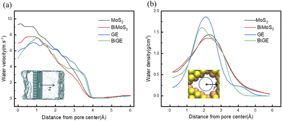 |
| | Fig. 5 (a) Axial velocity of water molecules in z-direction for the four nanopores. (b) Mass density profiles of water molecules in the four pores along the radial direction (xy-plane). The insets illustrate the distance from pore center along the axes. | |
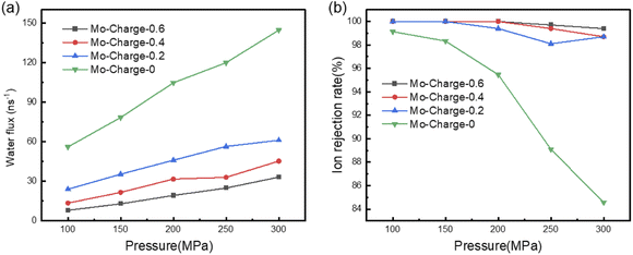
3.5. Effects of pore charge on water flux and ion rejection of BiMoS2 membrane
Eventually, we explored the effects of pore charge on water flux and ion rejection of BiMoS2 membrane. We varied the charges of Mo atoms on pore edge from 0 to 0.6 e. Correspondingly, the charges of S atoms are half of those of Mo atoms. The results were presented in Fig. 6. It can be seen that the water flux decreases rapidly with the increase of the charges of MoS2 on the pore edge. For example, the water fluxes are 78.46, 35.40, 21.63 and 12.95 ns−1 at 150 MPa, when the charges of Mo are 0, 0.2, 0.4 and 0.6 e. That is, the increase of the polarity of pore edge causes the decrease of water flux, which is attributed to the polar interactions between MoS2 and water molecules. On the contrary, the polarity of MoS2 on the pore edge play a positive role in ion rejection. Similarly, taking rejection rate at 150 MPa as an example, we found that the ion rejection rates are almost 100%, when the charges of Mo atoms on the pore edge are 0.2, 0.4 and 0.6 e. Even if the external pressure increases to 300 MPa, the ion rejection rates are 98.7%, 98.7% and 99.4%, when the charges of Mo atoms are 0.2, 0.4 and 0.6 e. However, the ion rejection rate falls sharply to 84.6% if the atoms on pore edge are uncharged. As a result, increasing the pore charge enhances the ion rejection.
 |
| | Fig. 6 BiMoS2 water flux and ion repulsion for different charges. (a) Water flux and (b) ion repulsion rate as a function of applied pressure of BiMoS2 nanopores. | |
4. Conclusions
Using MD simulations, we have compared the water flux and ion rejection of MoS2 monolayer, MoS2 bilayer, graphene monolayer and graphene bilayer with pore area ranging from 47 Å2 to 72 Å2. The results show that (1) the water flux of MoS2 is higher than that of graphene with similar pore area regardless of monolayer or bilayer; (2) monolayer has higher water flux than bilayer; (3) on the contrary, monolayer has lower ion rejection than bilayer. On the other hand, increasing pore area or applied pressure leads to higher water permeability but with lower ion rejection. Considering that the membranes prepared in the experiments are often multi-layered, we propose that MoS2 bilayer with pore area of 64 Å2 is most suitable for water desalination. In addition, increasing the polarity of pore edge play a negative role in water flux but a positive role in ion rejection.
Conflicts of interest
The authors declare no competing financial interests.
Acknowledgements
This work was supported by the National Natural Science Foundation of China (Grant No. 11875236, 12075212, 12105246), the Zhejiang Provincial Natural Science Foundation of China (Grant No. LY22A040008).
References
- M. A. Shannon, P. W. Bohn, M. Elimelech, J. G. Georgiadis, B. J. Mariñas and A. M. Mayes, Nature, 2008, 452, 301–310 CrossRef CAS PubMed
 .
. - D. Cohen-Tanugi, R. K. McGovern, S. H. Dave, J. H. Lienhard and J. C. Grossman, Energy Environ. Sci., 2014, 7, 1134–1141 RSC .
- L. Wang, M. S. H. Boutilier, P. R. Kidambi, D. Jang, N. G. Hadjiconstantinou and R. Karnik, Nat. Nanotechnol., 2017, 12, 509–522 CrossRef CAS PubMed .
- L. Sun, Y. Ying, H. Huang, Z. Song, Y. Mao, Z. Xu and X. Peng, ACS Nano, 2014, 8, 6304–6311 CrossRef CAS PubMed .
- S. Qin, D. Liu, G. Wang, D. Portehault, C. J. Garvey, Y. Gogotsi, W. Lei and Y. Chen, J. Am. Chem. Soc., 2017, 139, 6314–6320 CrossRef CAS PubMed .
- C. E. Ren, K. B. Hatzell, M. Alhabeb, Z. Ling, K. A. Mahmoud and Y. Gogotsi, J. Phys. Chem. Lett., 2015, 6, 4026–4031 CrossRef CAS PubMed .
- D. Jiang, V. R. Cooper and S. Dai, Nano Lett., 2009, 9, 4019–4024 CrossRef CAS .
- Z. Cao, V. Liu and A. Barati Farimani, ACS Energy Lett., 2020, 5, 2217–2222 CrossRef CAS .
- S. S. Shenvi, A. M. Isloor and A. F. Ismail, Desalination, 2015, 368, 10–26 CrossRef CAS .
- S. P. Koenig, L. Wang, J. Pellegrino and J. S. Bunch, Nat. Nanotechnol., 2012, 7, 728–732 CrossRef CAS PubMed .
- S. P. Surwade, S. N. Smirnov, I. V. Vlassiouk, R. R. Unocic, G. M. Veith, S. Dai and S. M. Mahurin, Nat. Nanotechnol., 2015, 10, 459–464 CrossRef CAS PubMed .
- Z. Song and Z. Xu, Sci. Rep., 2015, 5, 10597 CrossRef CAS PubMed .
- D. Jiang, V. R. Cooper and S. Dai, Nano Lett., 2009, 9, 4019–4024 CrossRef CAS PubMed .
- K. Celebi, J. Buchheim, R. M. Wyss, A. Droudian, P. Gasser, I. Shorubalko, J.-I. Kye, C. Lee and H. G. Park, Science, 2014, 344, 289–292 CrossRef CAS PubMed .
- Q. Xu, H. Xu, J. Chen, Y. Lv, C. Dong and T. S. Sreeprasad, Inorg. Chem. Front., 2015, 2, 417–424 RSC .
- M. E. Suk and N. R. Aluru, J. Phys. Chem. Lett., 2010, 1, 1590–1594 CrossRef CAS .
- D. Cohen-Tanugi, L.-C. Lin and J. C. Grossman, Nano Lett., 2016, 16, 1027–1033 CrossRef CAS PubMed .
- W. Li, Y. Yang, J. K. Weber, G. Zhang and R. Zhou, ACS Nano, 2016, 10, 1829–1835 CrossRef CAS PubMed .
- R. K. Joshi, P. Carbone, F. C. Wang, V. G. Kravets, Y. Su, I. V. Grigorieva, H. A. Wu, A. K. Geim and R. R. Nair, Science, 2014, 343, 752–754 CrossRef CAS PubMed .
- R. R. Nair, H. A. Wu, P. N. Jayaram, I. V. Grigorieva and A. K. Geim, Science, 2012, 335, 442–444 CrossRef CAS PubMed .
- S. Zeng, Y. Ji, Y. Shen, R. Zhu, X. Wang, L. Chen and J. Chen, RSC Adv., 2020, 10, 8744–8750 RSC .
- S. Kumar Kannam, B. D. Todd, J. S. Hansen and P. J. Daivis, Chem. Phys., 2012, 136, 024705 Search PubMed .
- M. C. Gordillo and J. Martí, Phys. Rev. B: Condens. Matter Mater. Phys., 2008, 78, 075432 CrossRef .
- J. Martí, J. Sala and E. Guàrdia, J. Mol. Liq., 2010, 153, 72–78 CrossRef .
- S. Zheng, Q. Tu, J. J. Urban, S. Li and B. Mi, ACS Nano, 2017, 11, 6440–6450 CrossRef CAS .
- C.-N. Yeh, K. Raidongia, J. Shao, Q.-H. Yang and J. Huang, Nat. Chem., 2015, 7, 166–170 CrossRef CAS .
- H. Huang, Y. Mao, Y. Ying, Y. Liu, L. Sun and X. Peng, Chem. Commun., 2013, 49, 5963 RSC .
- L. S. Melro, R. Pyrz and L. R. Jensen, IOP Conf. Ser.: Mater. Sci. Eng., 2016, 139, 012036 Search PubMed .
- M. Hu and B. Mi, Environ. Sci. Technol., 2013, 47, 3715–3723 CrossRef CAS .
- H. Liu, H. Wang and X. Zhang, Adv. Mater., 2015, 27, 249–254 CrossRef CAS PubMed .
- H.-H. Huang, R. K. Joshi, K. K. H. De Silva, R. Badam and M. Yoshimura, J. Membr. Sci., 2019, 572, 12–19 CrossRef CAS .
- Y. Zhang, K. Su and Z. Li, J. Membr. Sci., 2018, 563, 718–725 CrossRef CAS .
- L. Sun, H. Huang and X. Peng, Chem. Commun., 2013, 49, 10718 RSC .
- J. Feng, M. Graf, K. Liu, D. Ovchinnikov, D. Dumcenco, M. Heiranian, V. Nandigana, N. R. Aluru, A. Kis and A. Radenovic, Nature, 2016, 536, 197–200 CrossRef CAS PubMed .
- H. Li, T.-J. Ko, M. Lee, H.-S. Chung, S. S. Han, K. H. Oh, A. Sadmani, H. Kang and Y. Jung, Nano Lett., 2019, 19, 5194–5204 CrossRef CAS .
- Y. Li, S. Yang, K. Zhang and B. Van der Bruggen, Desalination, 2019, 454, 48–58 CrossRef CAS .
- M. Heiranian, A. B. Farimani and N. R. Aluru, Nat. Commun., 2015, 6, 8616 CrossRef CAS PubMed .
- J. Kou, J. Yao, L. Wu, X. Zhou, H. Lu, F. Wu and J. Fan, Phys. Chem. Chem. Phys., 2016, 18, 22210–22216 RSC .
- J. Azamat and A. Khataee, Comput. Mater. Sci., 2017, 137, 201–207 CrossRef CAS .
- A. B. Farimani, K. Min and N. R. Aluru, ACS Nano, 2014, 8, 7914–7922 CrossRef CAS PubMed .
- W. Humphrey, A. Dalke and K. Schulten, J. Mol. Graphics, 1996, 14, 33–38 CrossRef CAS .
- S. Plimpton, J. Comput. Phys., 1995, 117, 1–19 CrossRef CAS .
- P. Mark and L. Nilsson, J. Phys. Chem. A, 2001, 105, 9954–9960 CrossRef CAS .
- M. P. Allen and D. J. Tildesley, Computer simulation of liquids, Clarendon Press and Oxford University Press, Oxford, England and New York, 1987 Search PubMed .
- S. Nosé, J. Chem. Phys., 1984, 81, 511–519 CrossRef .
- W. G. Hoover, Phys. Rev. A, 1985, 31, 1695–1697 CrossRef .
- Q. Tan, Y. Fan, Z. Song, J. Chen and L. Chen, J. Mol. Model., 2022, 28, 57 CrossRef CAS PubMed .
- Z. Wang, Q. Tu, S. Zheng, J. J. Urban, S. Li and B. Mi, Nano Lett., 2017, 17, 7289–7298 CrossRef CAS PubMed .
- S. Gravelle, L. Joly, F. Detcheverry, C. Ybert, C. Cottin-Bizonne and L. Bocquet, Proc. Natl. Acad. Sci. U. S. A., 2013, 110, 16367–16372 CrossRef CAS PubMed .
|
| This journal is © The Royal Society of Chemistry 2022 |
Click here to see how this site uses Cookies. View our privacy policy here. 
 Open Access Article
 This Open Access Article is licensed under a Creative Commons Attribution-Non Commercial 3.0 Unported Licence
 a and
Junlang Chen
a and
Junlang Chen


