 Open Access Article
Rational construction of yolk–shell CoP/N,P co-doped mesoporous carbon nanowires as anodes for ultralong cycle life sodium-ion batteries†
Zhiya Lin ac,
Xueqing Tanb,
Yanping Lina,
Jianping Lina,
Wenyu Yanga,
Zhiqiang Huangb,
Shaoming Ying*b and
Xiaohui Huang
 *b
*b
aCollege of Mathematics and Physics, Ningde Normal University, Ningde 352100, China
bCollege of Chemistry and Materials, Fujian Provincial Key Laboratory of Featured Materials in Biochemical Industry, Ningde Normal University, Ningde 352100, China. E-mail: yingshaoming@126.com; 11429721@qq.com
cCollege of Physics and Energy, Fujian Provincial Solar Energy Conversion and Energy Storage Engineering Technology Research Center, Fujian Normal University, Fuzhou 350117, China
First published on 5th October 2022
Abstract
Owing to the natural abundance and low-cost of sodium, sodium-ion batteries offer advantages for next-generation portable electronic devices and smart grids. However, the development of anode materials with long cycle life and high reversible capacity is still a great challenge. Herein, we report a yolk–shell structure composed of N,P co-doped carbon as the shell and CoP nanowires as the yolk (YS–CoP@NPC) for a hierarchically nanoarchitectured anode for improved sodium storage performance. Benefitting from the 1D hollow structure, the YS–CoP@NPC electrode exhibits an excellent cycling stability with a reversibly capacity of 211.5 mA h g−1 at 2 A g−1 after 1000 cycles for sodium storage. In-depth characterization by ex situ X-ray photoelectron spectroscopy and work function analysis revealed that the enhanced sodium storage property of YS–CoP@NPC might be attributed to the stable solid electrolyte interphase film, high electronic conductivity and better Na+ diffusion kinetics.
1. Introduction
Sodium ion batteries (SIBs) have been recently considered as an attractive alternative to Li-ion batteries (LIBs) for large-scale and affordable electric energy storage applications due to the wide distribution and natural abundance of sodium.1–3 However, the larger ionic radius of Na+ (0.102 nm) when compared with that of Li+ (0.076 nm), results in sluggish Na+ diffusion kinetics, an unstable solid electrolyte interphase (SEI) layer and extremely serious volume expansion of the anode materials, thereby leading to poor long-term cycling stability and high-rate capability of SIBs.4–6 Therefore, the development and design of appropriate anode materials for SIBs which allow for stable Na+ insertion/de-insertion and also exhibit high irreversible capacity, fast diffusion pathways and excellent rate capability are an enormous challenge. For this reason, various anode materials, such as metal oxides/sulfides/phosphides,7–15 carbon materials16–18 and alloy materials19–21 have been investigated.Among the anode materials for SIBs, metal phosphides (MxPy, M = Fe, Co, Mo, Ni, etc. x, y = 1, 2, 3, etc.) have drawn increasing attention owing to their high theoretical capacity and low redox potential.13,22–24 Among them, CoP has relative low intercalation potential for Na/Na+ and high theoretical specific capacity of 894 mA h g−1, which makes CoP more favorable possibility for sodium storage.25 However, CoP anodes used for SIBs still face the fast capacity fading and poor cycling stability due to the sluggish Na+ diffusion kinetics, poor electrical conductivity and drastic volume change during the sodiation/desodiation process.26,27 Therefore, enhancing intrinsic electrical conductivity and constructing reasonable microstructure have become the main research emphasis of CoP. To overcome above issues, various strategies like rational nanostructure design, hybridized with carbon-based materials and metallic element doping have been explored. For example, Tao and co-workers28 prepared Co1−xMoxP/NC as anodes for SIBs, and exhibited an extraordinary discharge capacity of 160 mA h g−1 at 1 A g−1 over 1000 cycles. Jia et al.29 synthesized CoP@nitrogen-doped porous carbon as an anode, which displayed a specific capacity of 230 mA h g−1 after 370 cycles at 0.2 A g−1. Li et al.30 reported that CoP@C embedded into N/S-co-doped porous carbon sheets as anode for SIBs delivered a stable specific capacity of 162.4 mA h g−1 at 5 A g−1 after 150 cycles. Liu et al.31 prepared Mxene@CoP@NPC as anodes for SIBs, the MXene@CoP@NPC anode exhibits outstanding rate capability with a highly reversible capacity of 198 mA h g−1 at 5.0 A g−1. Despite these strategies could help to facilitate electron and ion transport for a partly enhanced electrochemical performance for SIBs, it is still inadequate in preventing capacity fading during repeated cycle caused by cracking and pulverization of the active materials.32 One solution to solve these issues is to synthesis nanostructures with interior void space, which could shorten the Na+ diffusion distance and buffer the volume expansion simultaneously. Yolk–shell (YS) structured nanomaterials have been verified as a promising strategy toward improving sodium storage.33 YS nanostructures contain unique large interior void space and short diffusion pathway, which can mitigate the aggregation of active materials and handle the problems of volume change, thus improving the performance of SIBs.
In this work, we have rational designed and synthesized a unique CoP/N,P co-doped mesoporous carbon nanowires (YS–CoP@NPC) nanostructure using a flexible etching method coupled with a facile phosphating strategy. The as-synthesized YS–CoP@NPC anode material is advantageous in improving the electrochemical property with high electronic/ion conductivity and enhanced mechanical stability. Consequently, when used as an anode materials for SIBs, this electrode shows desirable rate capability and outstanding long-term cycling stability. It achieves a high specific capacity of 211.5 mA h g−1 at 2 A g−1 after 1000 cycles. The improved performance of the YS–CoP@NPC could be mainly attributed to the YS structure, the synergistic effect between CoP and N,P co-doped carbon layer.
2. Experimental
2.1 Synthesis of 1D Co(OH)2 nanowires precursor
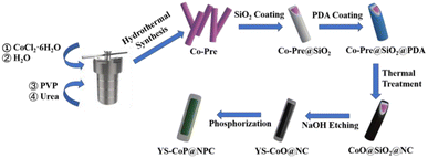
In a typical process, 0.7 g CoCl2·6H2O, 0.67 g PVP and 0.36 g urea are dispersed into 48 mL de-ionized water. After being continuously stirred for 15 min, the obtained suspension is transferred into a 50 mL Teflon-lined stainless steel autoclave, sealed and maintained at 120 °C for 12 h. The Co(OH)2 nanowires precursor (Co-Pre) products were collected by suction filtration and wished with water/absolute alcohol several times, and then dried at 60 °C.2.2 Synthesis of Co-Pre@SiO2 composites
For SiO2 coating, 0.2 g Co-Pre nanowires was first dispersed by ultrasonication in a mixture consisting 400 mL of 2-propanol and 40 mL of deionized water, followed by adding 60 mL of ammonia (25–28%) and 1 mL of tetraethyl-orthosilicate to the beaker, then the reaction was continued stirring for 15 h. The Co-Pre@SiO2 products were collected by suction filtration and wished with deionized water/absolute alcohol several times, then dried at 60 °C.2.3 Synthesis of Co-Pre@SiO2 composites
Typically, 0.1 g Co-Pre@SiO2 were first dispersed into 250 mL tris-buffer solution (pH = 8.5) by ultrasonication for 1 h. Then, 0.6 g of dopamine hydrochloride (PDA) was added into the above solution, which was kept stirring for 24 h. The products Co-Pre@SiO2@PDA was collected through suction filtration and wished with deionized water/absolute alcohol several times, and then dried at 60 °C. After annealing the particles at 400 °C for 2 h, the SiO2 layer was dissolved in 250 ml 1 M NaOH solution at 55 °C for 24 h to yield the YS–CoO@NC nanocomposites. The as-prepared Co-Pre or YS–CoO@NC and NaPO2H2·H2O with a weight ratio of (1![[thin space (1/6-em)]](https://www.rsc.org/images/entities/char_2009.gif) :
:![[thin space (1/6-em)]](https://www.rsc.org/images/entities/char_2009.gif) 10) were put at two positions in a corundum boat and calcined at 250 °C in Ar atmosphere for 2 h. Then the CoP and YS–CoP@NPC composites were obtained (Fig. 1).
10) were put at two positions in a corundum boat and calcined at 250 °C in Ar atmosphere for 2 h. Then the CoP and YS–CoP@NPC composites were obtained (Fig. 1).
2.4 Materials characterization
The crystalline phase and microstructure of the as-prepared Co-Pre, YS–CoO@NC, CoP and YS–CoP@NPC composites was investigated by powder X-ray diffractometry (XRD, BRUKER D8 ADVANCE) with Cu-Kα radiation (λ = 0.15406 nm), scanning electron microscopy (SEM, SU8010) and transmission electron microscopy (TEM, TJEOL JEM 2100). The elemental distribution are further identified by energy-dispersive X-ray spectroscopy (EDS). The surface potentials of CoP and YS–CoP@NPC electrodes are measured by Kelvin probe atomic force microscopy (KPAFM) (Bruker dimension ICON). The valence states of YS–CoP@NPC is analysed by X-ray photoelectron spectroscope (XPS ESCALAB 250Xi). The Raman spectrum were tested by a Horiba/Jobin Yvon Raman instrument. The carbon content in the YS–CoP@NPC composite was determined by a TG-DSC simultaneous thermal analyzer (STA449F3, NETZSCH) up to 600 °C at a heating rate of 10 °C min−1 in an air atmosphere.2.5 Cell fabrication and characterization
The sodium storage property of active material (CoP or YS–CoP@NPC) are evaluated with CR2025-type coin cells. The CoP or YS–CoP@NPC are mixed with Super-P (SP) and polyvinylidene fluoride (PVDF) binder in a mass ratio of 7![[thin space (1/6-em)]](https://www.rsc.org/images/entities/char_2009.gif) :
:![[thin space (1/6-em)]](https://www.rsc.org/images/entities/char_2009.gif) 2
2![[thin space (1/6-em)]](https://www.rsc.org/images/entities/char_2009.gif) :
:![[thin space (1/6-em)]](https://www.rsc.org/images/entities/char_2009.gif) 1 in N-methyl pyrrolidinone (NMP) to form homogeneous slurry, which is then cast onto a copper foil and subsequently dried in vacuum at 110 °C for 12 h. After vacuum drying at 110 °C for 12 h, electrode discs with a diameter of 12.5 mm were punched out and weighed. The loading density of the active materials was ∼1.4 mg cm−2. The coin cells are assembled in an argon-filled glove box with 1 M NaClO4 in propylene carbonate (PC) solvent (5 vol% FEC) addition as electrolyte, glass fiber (Whatman GF/F) as separators, and sodium foil is used the anode and counter electrode. The electrochemical properties are carried out in the voltage range of 0.01–3.0 V using a LAND multichannel battery test system. AC impedance (EIS) and Cyclic voltammetry (CV) of the CoP or YS–CoP@NPC were measurement using a Metrohm-Autolab (PGSTAT302N) electrochemical workstation.
1 in N-methyl pyrrolidinone (NMP) to form homogeneous slurry, which is then cast onto a copper foil and subsequently dried in vacuum at 110 °C for 12 h. After vacuum drying at 110 °C for 12 h, electrode discs with a diameter of 12.5 mm were punched out and weighed. The loading density of the active materials was ∼1.4 mg cm−2. The coin cells are assembled in an argon-filled glove box with 1 M NaClO4 in propylene carbonate (PC) solvent (5 vol% FEC) addition as electrolyte, glass fiber (Whatman GF/F) as separators, and sodium foil is used the anode and counter electrode. The electrochemical properties are carried out in the voltage range of 0.01–3.0 V using a LAND multichannel battery test system. AC impedance (EIS) and Cyclic voltammetry (CV) of the CoP or YS–CoP@NPC were measurement using a Metrohm-Autolab (PGSTAT302N) electrochemical workstation.
3. Results and discussion
3.1 Material characterization
The crystalline phase of the as-prepared Co-Pre, YS–CoO@NC, CoP and YS–CoP@NPC were first investigated via XRD and Raman spectroscopy. It is found that the diffraction peaks of solvothermal product are well indexed into Co(OH)2 (Fig. S1†) phase (JCPDS No. 30-0443). Fig. 2(a) shows XRD patterns of the as-synthesized YS–CoO@NC, CoP and YS–CoP@NPC composites. It is found that after annealing the particles at 400 °C for 2 h, the product are well indexed into CoO phase (JCPDS No. 48-1719).34 The diffraction peaks at 31.5°, 35.4°, 36.2°, 46.3°, 48.2°, 52.3° and 56.8° are corresponding to the (011), (200), (111), (112), (211), (103) and (301) planes of CoP (JCPDS card No. 29-0497).35 The Raman spectra over the range of 400–2000 cm−1 further confirm the existence of carbon in the YS–CoP@NPC composite (Fig. 2(b)). TG reveals that the hybrid materials have a chemical composition of 94 wt% YS–CoP@NPC and 6 wt% carbon, shown in Fig. S2.† The surface valence states of the YS–CoP@NPC products are detect by XPS. The full survey scan spectrum (Fig. S3†) confirms that YS–CoP@NPC samples consist of Co, P, C and N elements consistent with the subsequent EDX observation. As shown in Fig. 2(c), the peaks at 782.3 eV and 798.3 eV are the typical peaks of Co 2p3/2 and Co 2p1/2 of the Co–P bond and the peaks at 778.8 eV correspond to oxidized Co species which arose from the superficial oxidation, respectively.36 Three peaks located at 803.2, 786.8 and 784.0 eV in the Co 2p spectrum can be considered as the shakeup excitation of the high-spin Co2+ ions.37 The spectrum of the P 2p (Fig. 2(d)) could be can be separated to two peaks at 129.6 and 134.2 eV, corresponding to the characteristic binding energies for P 2p and Co 2p contributions in CoP and the excessive exposure of P on the surface to the air.38 The high-resolution C 1s spectrum Fig. 2(e) demonstrates four peaks at 284.8 eV, 288.3, 286.9 and 286.3 eV assigning to C–C/C![[double bond, length as m-dash]](https://www.rsc.org/images/entities/char_e001.gif) C, C–P, C
C, C–P, C![[double bond, length as m-dash]](https://www.rsc.org/images/entities/char_e001.gif) O and C–N–C bonds, respectively.39 The presence of C–P bonds in carbon layers have been reported that they are beneficial for capacities by enhancing the Na-absorption.40 Three peaks at 398.6, 399.8 and 401.2 eV in the N 1s spectrum shown in Fig. 2(f) correspond to pyridinic nitrogen, pyrrolic nitrogen and graphitic nitrogen, respectively.41 It has been reported that pyridinic nitrogen and pyrrolic nitrogen as electrochemically active sites, could facilitate the fast diffusion of reactive Na-ions and improve the surface-induced capacitive processes involving Na-ions.40,41
O and C–N–C bonds, respectively.39 The presence of C–P bonds in carbon layers have been reported that they are beneficial for capacities by enhancing the Na-absorption.40 Three peaks at 398.6, 399.8 and 401.2 eV in the N 1s spectrum shown in Fig. 2(f) correspond to pyridinic nitrogen, pyrrolic nitrogen and graphitic nitrogen, respectively.41 It has been reported that pyridinic nitrogen and pyrrolic nitrogen as electrochemically active sites, could facilitate the fast diffusion of reactive Na-ions and improve the surface-induced capacitive processes involving Na-ions.40,41
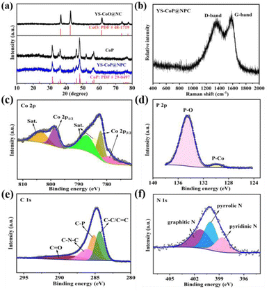 | ||
| Fig. 2 (a) XRD patterns of YS–CoO@NC, CoP and YS–CoP@NPC powders. (b) Raman spectra of YS–CoP@NPC. XPS spectra of (c) Co 2p, (d) P 1s, (e) C 1s and (f) N 1s of YS–CoP@NPC. | ||
The microstructure of the as-prepared Co-Pre, YS–CoO@NC, CoP and YS–CoP@NPC are characterized by SEM and TEM. The SEM image (Fig. 3(a)) reveals that the Co-Pre nanowires have a diameter of 50–100 nm and a length of several micrometers. A uniform and smooth SiO2 layer is then loaded on the surface of the Co-Pre (Fig. 3(b)). Fig. 3(c) presents the low magnification SEM images of Co-Pre@SiO2@PDA sample, showing the high quality of the homogeneous and uniform nanoparticles. TEM images in Fig. 3(e and f) further reveal that the Co-Pre cores approximately 100 nm in diameter entirely wrapped by the homogeneously PDA shells with an average thickness of ∼57 nm and ∼29 nm SiO2 in between. EDS elemental mapping spectra clearly show that Co, Si and N are evenly distributed throughout the composites (Fig. 3(g–j)). SEM images of YS–CoO@NC are shown in Fig. 3(f). A visible interlayer gap is clearly observed between the carbon shell and the CoO core, which is a result of etching the SiO2 interlayer to generate the void space. The TEM (Fig. S5(a)†) images of YS–CoO@NC clearly reflect the CoO nanoparticles are uniformly wrapped by the 1D carbon shells. A visible interlayer gap is clearly observed between the carbon shells and the CoO core. Furthermore, the HRTEM image in Fig. S5(b)† clearly displays a set of parallel fringes with a d-spacing of 0.251 nm, corresponding to the (111) plane of CoO. Fig. S5(c–g)† reveals the existence and homogeneous distribution of C, N, Co and O elements throughout the selected zone of the YS–CoO@NC powder.
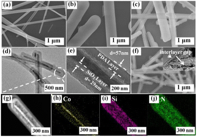 | ||
| Fig. 3 SEM images of (a) Co-Pre, (b) Co-Pre@SiO2, (c) Co-Pre@SiO2@PDA, (f) YS–CoO@NC. TEM images (d and e) and element maps (g–j) of Co-Pre@SiO2@PDA. | ||
SEM images of CoP are shown in Fig. 4(a). After phosphating at 250C for 2 h, bare CoP powder have a slight agglomeration. In contrast, YS–CoP@NPC (Fig. 4(b and c)) product can retain its nanowires structure well, indicating that carbon shell would stabilize the structure of the active materials. It is expected that carbon shell would be acted as a dimension restrictor for keeping the morphology of the nanostructured precursors during the phosphating process. The TEM (Fig. 4(d and e)) images of YS–CoP@NPC clearly reflect the CoP nanoparticles are uniformly wrapped by the 1D carbon shells. A visible void space is clearly observed between the carbon shells and the CoP core. The thickness of the carbon shells is confirmed to be ∼34.1 nm as shown in Fig. 4(e). Furthermore, the HRTEM image in Fig. 4(f) clearly displays a set of parallel fringes with a d-spacing of 0.196 nm, corresponding to the (112) plane of CoP. EDS mapping results (Fig. 4(g–j)) show that the distribution of Co and P in YS–CoP@NPC, which verifies that the CoP cores are formed from the confined reaction of CoO with penetrated gas in the carbon nanowires.
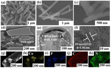 | ||
| Fig. 4 SEM images of (a) CoP and (b and c) YS–CoP@NPC. TEM (d and e) and HRTEM (f) images of YS–CoP@NPC. Element maps of (g–k) YS–CoP@NPC particles. | ||
3.2 Electrochemical measurements
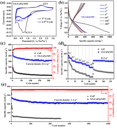
Fig. 4(a) shows CV curves of the YS–CoP@NPC nanocomposites for the first five cycles at a scan rate of 0.1 mV s−1 between 0.01 and 3.0 V. In the 1st cathodic scan, the well-defined current peaks were observed at ∼0.73 V, which is attributed to the irreversible decomposition of the electrolyte to form a SEI film and the reaction of CoP + Na+ + e− → Na3P + Co.28,41 In the first anodic process, a broad peak around ∼2.0 V mainly caused by the decomposition of Na3P, which correspond to the main reaction of Na3P + Co → CoP + 3Na+ + 3e−.30 Compared to the CV curves of CoP shown in Fig. S5(a),† it is observed from Fig. 5(a) that the peaks in the subsequent cycles overlap well, indicating that YS–CoP@NPC possesses excellent electrochemical reversibility and stability during the charge/discharge process. Fig. 5(b) presents the charge/discharge voltage profiles of the YS–CoP@NPC at a current density of 0.2 A g−1 for the 1st, 2nd, 3rd, 5th, 50th, 100th and 200th cycles. The initial discharge and charge capacities are 1000.3 and 415 mA h g−1. The initial irreversible capacity loss and low coulombic efficiency (CE) was mainly because of the formation of the SEI films and the decomposition of the electrolyte, which appears commonly for anode materials.29,41,42 After 200 cycles, the CoP electrode only delivers a discharge capacity of 56.7 mA h g−1 Fig. S5(b),† which is much lower than that of the YS–CoP@NPC (315.9 mA h g−1). In addition, the degree of bending of the plateau reflects the polarization of the electrodes. In comparison, YS–CoP@NPC demonstrates lower polarization and better reaction kinetics, resulting from the enhanced electrical conductivity induced by the carbon in the composite.Fig. 5(c) contrastively exhibits the galvanostatic cycling ability of the YS–CoP@NPC and CoP at a current density of 0.2 A g−1. It can be seen that the discharge capacity of the CoP fade steeply and the specific discharge capacity is only 51.6 mA h g−1 after 220 cycles. By comparison, designed with a YS structure and coated with carbon layer ensure the YS–CoP@NPC with enhanced cycling stability. A specific discharge capacity of 317.3 mA h g−1 can be maintained after 220 repeated cycles. The rate property of the CoP and YS–CoP@NPC anodes at different current density from 0.2 A g−1 to 2 A g−1 between 0.01∼3 V were also investigated and shown in Fig. 5(d). As can be seen in Fig. 5(d), YS–CoP@NPC exhibits higher capacity (0.2 A g−1: 427.9 mA h g−1; 0.5 A g−1: 358.1 mA h g−1; 1 A g−1: 320.2 mA h g−1; 2 A g−1: 274 mA h g−1, respectively) than that of the CoP (0.2 A g−1: 214.3 mA h g−1; 0.5 A g−1: 118.7 mA h g−1; 1 A g−1: 78.1 mA h g−1; 2 A g−1: 50 mA h g−1, respectively). Furthermore, the capacity of the YS–CoP@NPC could quickly resume to 420.2 mA h g−1 when the current rate goes back to 0.2 A g−1, indicating the remarkable Na+ storage property of YS–CoP@NPC. To judge a probable anode material in SIBs, a comparison of the electrochemical property between our work and other groups' work.26,27,43–47 Analysis from Fig. S6† suggests that high-rate YS–CoP@NPC in our work has potential application in fast-charging SIBs. More satisfactorily, YS–CoP@NPC demonstrates an ultra-long cycle life (Fig. 5(e)), a discharge capacity of 211.5 mA h g−1 was retained for the YS–CoP@NPC electrode after 1000 cycles, while the CoP electrode delivers merely 34.7 mA h g−1 after 510 cycles. It is noteworthy that after the first several cycles, the coulombic efficiency of YS–CoP@NPC increases to approximately 100%, implying a superior reversibility during the cycling process. The great sodium storage properties of the YS–CoP@NPC can be attributed to the advantageous structural design and N,P co-doped carbon layer. To gain further insight into the cycling stability of YS–CoP@NPC, the morphologies of CoP and YS–CoP@NPC electrodes before cycle and after 50 cycles are studied, as shown in Fig. S7(a–d).† It is clear that CoP powder has serious structural deterioration and loses its original morphology, increasing interfacial resistance among particles and reducing the contact areas between active materials and the electrolyte. In contrast, YS–CoP@NPC sample can retain its nanowires structure well, indicating that YS structure would stabilize the structure of the active materials and consequently improved the cycling stability. Furthermore, the microstructure can also be observed from the TEM images, which further demonstrates the nanowires structure of the CoP@NPC (Fig. S8(b)†).
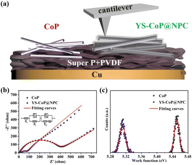
In order to further investigate the reaction kinetic, the EIS of CoP and YS–CoP@NPC samples were carried out by the SIB. As shown in Fig. 6(b), both EIS curves show an inclined line at the low frequency region and a depressed semicircle at the high frequency region, which reflects the Na+ diffusion process and the charge-transfer process, respectively.42 According to the equivalent circuit (inset of Fig. 6(b)), the values of Rct for the YS–CoP@NPC electrodes are calculated to be 97.5 Ω, much lower than that of CoP electrode (350.3 Ω), indicating facilitating the Na+ storage and enhanced charge transfer kinetics under the high current density. Work function (WF) defined as the minimum energy required for the loss of an electron from the inside of a bulk material to the vacuum, plays a fundamental role in most of the electronic properties of a material.48 Therefore, the higher the WF, the harder the loss of an electron from the material. The WF of the as-prepared samples are further detected by KPAFM and the work electrode including CoP and YS–CoP@NPC electrodes is given in Fig. 6(a). Fig. S9(a–c)† presents the surface potential images over a scan area of 200 nm × 200 nm of CoP, YS–CoP@NPC and Au foil respectively. According to our previous work,49 the WFs of CoP and YS–CoP@NPC are calculated and the corresponding results are presented in Fig. 6(c). It is found that YS–CoP@NPC has a lower WF (5.30 eV) than that of CoP (5.45 eV). The tested WF of CoP is in keeping with the reported value (5.45 eV).50 Higher WF requires more energy required for electrons to escape from the bulk materials. Therefore, N,P co-doped carbon layer is expected to facilitate electron transfer in composite, which is in consistent with the analysis of EIS measurements.
To get insight of the potential mechanism behind the superior electrochemical performance of YS–CoP@NPC, CV measurements are carried out at different sweep rates from 0.1 to 1 mV s−1, and the results are shown in Fig. S10(a).† The redox peak current (i) obeyed a power–law relationship to the sweep rate (v) as follows:51
| i = avb | (1) |
| i(v) = k1v + k2v1/2 | (2) |
During the first charge/discharge process, the SEI affords a passivation layer on the anode surface, which restraints further electrolyte decomposition and provides the long cycle life required for many applications.55 Therefore, without the generation of a stable SEI, SIBs would not be able to be reversibly sodiation/de-sodiation. In order to better understand the positive effects of N,P co-doped carbon layer on the enhanced interfacial stability of the YS–CoP@NPC anode materials, XPS analyses are carried out for the CoP and YS–CoP@NPC electrodes after the first cycle. As shown in Fig. 7(a and b), the O1s could be fitted with four separate peaks around at 530.9, 532.3, 533.8 and 535.8 eV, which are assigned to Na2O, RCH2ONa, ClO4− and Na KLL, respectively.56 In the C 1s XPS spectrum (Fig. 7(c and d)), the peaks observed at 290, 288.9, 286.7, and 284.8 eV are assigned to Na2CO3, O![[double bond, length as m-dash]](https://www.rsc.org/images/entities/char_e001.gif) C–O, C–O–C and C–C bonds, respectively. From O 1s and C 1s XPS spectrum, the presence of Na2O, RCH2ONa and Na2CO3 are assigned to the reduction of propylene carbonate (PC) solvent and is unfortunately thermodynamically unstable.57 As a negative product of side reaction, Na2CO3 and Na2O with poor electronic and ionic conductivity increase the electrode polarization and exacerbate the Na+ diffusion kinetics. Comparing to CoP electrodes, YS–CoP@NPC has relatively higher ClO4− and lower Na2CO3, Na2O, indicating that N,P co-doped carbon layer could efficiently reduce the side reaction and form a more stable SEI layer resulting in preventing the Na dendrite growth and improved lifetime. Therefore, the YS–CoP@NPC electrode obviously exhibited higher stable SEI than the CoP electrode during the whole sodiation/de-sodiation, revealing the faster Na+ diffusion kinetics of YS–CoP@NPC. This is possibly because of the high conductivity and structural stability of YS–CoP@NPC, which led to high capacity retention for YS–CoP@NPC electrode at high current density. These results support that the presence of carbon shell can lead to the formation of a stable SEI layer in the cycled YS–CoP@NPC electrodes. The stabilized SEI on the electrode surface can relieve the continued expenditure of electrolytes, facilitate the fast transport of Na+ across the SEI formed on the active materials, and lower interface impedance,57 leading to enhanced reversible capacity, capacity retention and rate capability.
C–O, C–O–C and C–C bonds, respectively. From O 1s and C 1s XPS spectrum, the presence of Na2O, RCH2ONa and Na2CO3 are assigned to the reduction of propylene carbonate (PC) solvent and is unfortunately thermodynamically unstable.57 As a negative product of side reaction, Na2CO3 and Na2O with poor electronic and ionic conductivity increase the electrode polarization and exacerbate the Na+ diffusion kinetics. Comparing to CoP electrodes, YS–CoP@NPC has relatively higher ClO4− and lower Na2CO3, Na2O, indicating that N,P co-doped carbon layer could efficiently reduce the side reaction and form a more stable SEI layer resulting in preventing the Na dendrite growth and improved lifetime. Therefore, the YS–CoP@NPC electrode obviously exhibited higher stable SEI than the CoP electrode during the whole sodiation/de-sodiation, revealing the faster Na+ diffusion kinetics of YS–CoP@NPC. This is possibly because of the high conductivity and structural stability of YS–CoP@NPC, which led to high capacity retention for YS–CoP@NPC electrode at high current density. These results support that the presence of carbon shell can lead to the formation of a stable SEI layer in the cycled YS–CoP@NPC electrodes. The stabilized SEI on the electrode surface can relieve the continued expenditure of electrolytes, facilitate the fast transport of Na+ across the SEI formed on the active materials, and lower interface impedance,57 leading to enhanced reversible capacity, capacity retention and rate capability.
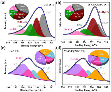 | ||
| Fig. 7 (a and b) O 1s and (c and d) C 1s XPS spectra of CoP and YS–CoP@NPC extracted from coin cells after first sodiation/desodiation cycles, respectively. | ||
The excellent sodium storage properties in terms of cycling stability and rate capability can be ascribed to the synergistic effects of the morphology size, structural stability and chemical compositions. The potential mechanism behind the improved performances for YS–CoP@NPC could be systematically investigated based on the YS structure, the synergistic effect between CoP and N,P co-doped carbon shell, shown in Fig. 8. First, the constructed interior void space between the CoP core and the carbon shell is large enough to mitigate the large volume change of CoP upon sodiation/desodiation, thus effectively relieving the issue of capacity fading. Second, N,P co-doped carbon shell offers a high-conductivity electron transport pathway, decreases the internal resistance among CoP particles. Third, the carbon shells can not only enhance the conductivity but also benefit to form a stable SEI layer during cycling.58 This N,P co-doped carbon shell is well maintained even when the CoP expands during the sodiation/desodiation processes, thanks to the enough void space of the YS structure.
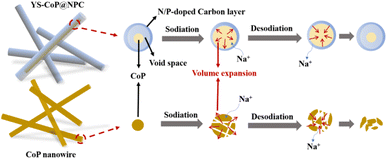 | ||
| Fig. 8 Schematic diagram of the Na-storage mechanism and morphology change in CoP and YS–CoP@NPC during cycling. | ||
4. Conclusions
In summary, we have rationally designed a yolk–shell CoP/N,P co-doped carbon (YS–CoP@NPC) for robust sodium storage. Benefiting from its unique structural features and the N,P co-doped carbon shell, the YS–CoP@NPC show remarkable rate capability and ultra-long cycling stability. In particular, they deliver a reversible capacity of 317.3 mA h g−1 after 220 cycles at a current density of 0.2 A g−1, and an satisfactorily ultra-long cycle life with a capacity of 211.5 mA h g−1 after 1000 cycles at 2 A g−1. This research may open a new avenue for the design and synthesis of CoP-base nanocomposites for high-performance SIBs.Conflicts of interest
There are no conflicts to declare.Acknowledgements
This work is supported by a grant from the Natural Science Foundations of Fujian Province of China (Grant No. 2021J05258, 2021J011151), the Project of Scientific Research of Ningde Normal University (Grant No. 2020Y06, 2020Y17), the Major Cultivation Program of Ningde Normal University (Grant No. 2021ZDK07, 2019ZDK012), the Innovation Team Project of Ningde Normal University (Grant No. 2021T07).References
- T. Perveen, M. Siddiq, N. Shahzad, R. Ihsan, A. Ahmad and M. I. Shahzad, Sustainable Energy Rev., 2020, 119, 109549 CrossRef CAS.
- X. Li, X. H. Sun, X. D. Hu, F. R. Fan, S. Cai, C. M. Zheng and G. D. Stucky, Nano Energy, 2020, 77, 105143 CrossRef CAS.
- C. Yang, S. Xin, L. Q. Mai and Y. You, Adv. Energy Mater., 2020, 11, 2000974 CrossRef.
- Y. Jiang, Y. C. Wang, J. F. Ni and L. Li, InfoMat, 2021, 3, 339–352 CrossRef CAS.
- Y. Wu and Y. Yu, Energy Storage Mater., 2019, 16, 323–343 CrossRef.
- G. Z. Fang, Z. X. Wu, J. Zhou, C. Y. Zhu, X. X. Cao, T. Q. Lin, Y. M. Chen, C. Wang, A. Q. Pan and S. Q. Liang, Adv. Energy Mater., 2018, 8, 1703155 CrossRef.
- M. N. Tahir, B. Oschmann, D. Buchholz, X. Dou, I. Lieberwirth, M. Panthöfer, W. Tremel, R. Zentel and S. Passerini, Adv. Energy Mater., 2016, 6, 1614–6832 CrossRef PubMed.
- L. Shi, Y. Li, F. L. Zeng, S. J. Ran, C. Y. Dong, S. Y. Leu, S. T. Boles and K. H. Lam, Chem. Eng. J., 2019, 356, 107–116 CrossRef CAS.
- P. Huang, M. Huang, H. Hu, Y. Zhong, C. Lai and S. L. Chou, J. Mater. Chem. A, 2019, 7, 26513–26523 RSC.
- F. X. Xie, L. Zhang, Q. F. Gu, D. L. Chao, M. Jaroniec and S. Z. Qiao, Nano Energy, 2019, 60, 591–599 CrossRef CAS.
- Y. Liu, Y. J. Fang, Z. W. Zhao, C. Z. Yuan and X. W. Lou, Adv. Energy Mater., 2019, 9, 1803052 CrossRef.
- G. M. Wang, X. X. Bi, H. L. Yue, R. C. Jin, Q. Y. Wang, S. M. Gao and J. Lu, Nano Energy, 2019, 60, 362–370 CrossRef CAS.
- Y. Zhang, G. Wang, L. Wang, L. Tang, M. Zhu, C. Wu, S. X. Dou and M. Wu, Nano Lett., 2019, 19, 2575–2582 CrossRef CAS.
- C. M. Fu, H. Yang, G. F. Feng, L. N. Wang and T. X. Liu, Electrochim. Acta, 2020, 358, 136921 CrossRef CAS.
- K. H. Nam, Y. Hwa and C. M. Park, ACS Appl. Mater. Interfaces, 2020, 12, 15053–15062 CrossRef CAS PubMed.
- L. C. Yue, H. T. Zhao, Z. G. Wu, J. Liang, S. Y. Lu, G. Chen, S. Y. Gao, B. H. Zhong, X. D. Guo and X. P. Sun, J. Mater. Chem. A, 2020, 8, 11493–11510 RSC.
- W. W. Hong, Y. Zhang and L. Yang, Nano Energy, 2019, 65, 104038 CrossRef CAS.
- L. F. Xiao, H. Y. Lu, Y. J. Fang, M. L. Sushko, Y. L. Cao, X. P. Ai, H. X. Yang and J. Liu, Adv. Energy Mater., 2018, 8, 1–7 Search PubMed.
- M. W. Orzech, F. Mazzali, J. D. McGettrick, C. P. Pearce, T. M. Watson, W. Voice, D. Jarvis and S. Margadonna, J. Mater. Chem. A, 2017, 5, 23198–23208 RSC.
- H. Yin, W. Shen, H. Q. Qu, C. Li and M. Q. Zhu, Nano Energy, 2020, 70, 104468 CrossRef CAS.
- H. L. Jin, H. Lu, W. Y. Wu, S. Q. Chen, T. C. Liu, X. X. Bi, W. N. Xie, X. Chen, K. Q. Yang, J. Li, A. L. Liu, Y. Lei, J. C. Wang, S. Wang and J. Lu, Nano Energy, 2020, 70, 104569 CrossRef CAS.
- S. S. Shi, Z. Li, L. Y. Shen, X. P. Yin, Y. M. Liu, G. L. Chang, J. Wang, S. M. Xu, J. J. Zhang and Y. F. Zhao, Energy Storage Mater., 2020, 29, 78–83 CrossRef.
- S. S. Shi, Z. P. Li, Y. Sun, B. Wang, Q. N. Liu, Y. L. Hou, S. F. Huang, J. Y. Huang and Y. F. A. Zhao, Nano Energy, 2018, 48, 510–517 CrossRef CAS.
- Q. D. Guo, H. J. Shao, K. F. Zhang, G. T. Chen, W. J. Kong, X. M. Feng, Y. Gao, Y. P. Liu, N. Wang, C. F. Dong and F. Y. Jiang, ChemElectroChem, 2021, 8, 2022–2027 CrossRef CAS.
- W. J. Li, Q. R. Yang, S. L. Chou, J. Z. Wang and H. K. Liu, J. Power Sources, 2015, 294, 627–632 CrossRef CAS.
- Q. N. Liu, Z. Hu, Y. R. Liang, L. Li, C. Zou, H. L. Jin, S. Wang, H. M. Lu, Q. F. Gu, S. L. Chou, Y. Liu and S. X. Dou, Angew. Chem., Int. Ed., 2020, 132, 5197–5202 CrossRef.
- H. Su, Y. Zhang, X. F. Liu, F. B. Fu, J. R. Ma, K. Li, W. B. Zhang, J. M. Zhang and D. Li, J. Colloid Interface Sci., 2021, 582, 969–976 CrossRef CAS PubMed.
- S. Tao, J. Q. Xu, T. H. Xie, S. Q. Chu, D. J. Wu, B. Qian, S. M. Chen and Li. Song, J. Power Sources, 2021, 500, 229975 CrossRef CAS.
- Q. Q. Chang, Y. H. Jin, M. Jia, Q. Yuan, C. C. Zhao and M. Q. Jia, J. Colloid Interface Sci., 2020, 575, 61–68 CrossRef CAS PubMed.
- H. Su, Y. Zhang, X. F. Liu, F. B. Fu, J. R. Ma, K. Li, W. B. Zhang, J. M. Zhang and D. Li, J. Colloid Interface Sci., 2021, 582, 969–976 CrossRef CAS PubMed.
- X. L. Liu, Z. T. Liu, W. Yang, M. Q. Wang, B. Y. Qin, Y. F. Zhang, Z. L. Liu and H. S. Fan, Mater. Today Chem., 2022, 26, 101002 CrossRef CAS.
- L. B. Ma, P. J. Yan, S. K. Wu, G. Y. Zhu and Y. L. Shen, J. Mater. Chem. A, 2017, 5, 16994–17000 RSC.
- C. Wu, X. Tong, Y. F. Ai, D. S. Liu, P. Yu, J. Wu and Z. M. M. Wang, Nano-Micro Lett., 2018, 10, 2–18 CrossRef PubMed.
- H. Qiao, L. F. Xiao, Z. Zheng, H. W. Liu, F. L. Jia and L. Z. Zhang, J. Power Sources, 2008, 185, 486–491 CrossRef CAS.
- B. Liu, R. Y. Wang, Y. Yao, J. Ma, Y. B. Sun, J. F. Wan, Y. Zhang, S. Q. Wang and J. L. Zou, Chem. Eng. J., 2022, 431, 133238 CrossRef CAS.
- F. F. Li, J. F. Gao, Z. H. He and L. B. Kong, ACS Appl. Mater. Interfaces, 2021, 13, 10071–10088 CrossRef CAS PubMed.
- J. L. Gu, L. Sun, Y. X. Zhang, Q. Y. Zhang, X. W. Li, H. C. Si, Y. Shi, C. Sun, Y. Gong and Y. H. Zhang, Chem. Eng. J., 2020, 385, 123454 CrossRef CAS.
- X. Zhang, X. Zhang, H. Xu, Z. Wu, H. Wang and Y. Liang, Adv. Funct. Mater., 2017, 27, 1606635 CrossRef.
- M. Jiang, W. Fan, A. Q. Zhu, P. F. Tan, J. P. Xie and J. Pan, Inorg. Chem. Front., 2021, 8, 2385–2394 RSC.
- H. J. Wang, J. L. Lan, H. C. Yuan, S. C. Luo, Y. Q. Huang, Y. H. Yu, Q. Cai and X. P. Yang, Appl. Surf. Sci., 2020, 518, 146221 CrossRef CAS.
- G. Q. Suo, J. Q. Zhang, D. Lia, Q. Y. Yu, W. Wang, M. He, L. Feng, X. J. Hou, Y. L. Yang, X. H. Ye and L. Zhang, Chem. Eng. J., 2020, 388, 124396 CrossRef CAS.
- J. Zhang, K. Zhang, J. Yang, G. H. Lee, J. Shin, V. W. H. Lau and Y. M. Kang, Adv. Energy Mater., 2018, 8, 1800283 CrossRef.
- S. Y. Hao, H. J. Li, Z. X. Zhao and X. M. Wang, ChemElectroChem, 2019, 6, 5712–5720 CrossRef CAS.
- Z. G. Yang, Q. Pan, Z. G. Wu, W. Xiang, F. Y. Fu, Y. Wang, L. Ji, B. H. Zhong, X. P. Sun and X. D. Guo, J. Alloys Compd., 2020, 848, 156285 CrossRef CAS.
- W. Huang, H. H. Shangguan, X. W. Zheng, C. Engelbrekt, Y. Yang, S. Li, K. Mlhave, X. X. Xiao, X. H. Lin, L. J. Ci and P. C. Si, Electrochim. Acta, 2021, 395, 139112 CrossRef CAS.
- Y. J. Wang, J. L. Bian, W. N. Ren and C. W. Cheng, Mater. Res. Bull., 2021, 139, 111248 CrossRef CAS.
- Q. Q. Chang, Y. H. Jin, M. Jia, Q. Yuan, C. C. Zhao and M. Q. Jia, J. Colloid Interface Sci., 2020, 575, 61–68 CrossRef CAS PubMed.
- J. M. Tao, L. Lu, B. Q. Wu, X. Y. Fan, Y. M. Yang, J. X. Li, Y. B. Lin, Y. Y. Li, Z. G. Huang and J. Lu, Energy Storage Mater., 2020, 29, 367–376 CrossRef.
- Z. Y. Lin, G. Z. Liu, Y. P. Zheng, Y. B. Lin and Z. G. Huang, J. Mater. Chem. A, 2018, 6, 22655–22662 RSC.
- H. N. Xing, W. J. He, Y. B. Liu, G. K. Long, Y. Sun, J. Feng, W. Feng, Y. Zhou, Y. Zong, X. H. Li, X. H. Zhu and X. L. Zheng, ACS Appl. Mater. Interfaces, 2021, 13, 26373–26383 CrossRef CAS PubMed.
- J. C. Pramudita, D. Sehrawat, D. Goonetilleke and N. Sharma, Adv. Energy Mater., 2017, 7, 1602911 CrossRef.
- H. W. Huang, J. Cui, G. X. Liu, R. Bi and L. Zhan, ACS Nano, 2019, 13, 3448–3456 CrossRef CAS PubMed.
- J. Cui, S. S. Yao, Z. H. Lu, J. Q. Huang, W. G. Chong, F. Ciucci and J. K. Kim, Adv. Energy Mater., 2018, 8, 1702488 CrossRef.
- J. T. Chen, B. J. Yang, H. J. Hou, H. X. Li, L. Liu, L. Zhang and X. B. Yan, Adv. Energy Mater., 2019, 19, 1803894 CrossRef.
- S. K. Heiskanen, J. J. Kim and B. L. Lucht, Joule, 2019, 3, 2322–2333 CrossRef CAS.
- L. W. Ji, M. Gu, Y. Y. Shao, X. L. Li, M. H. Engelhard, B. W. Arey, W. Wang, Z. M. Nie, J. Xiao, C. M. Wang, J. G. Zhang and J. Liu, Adv. Mater., 2014, 26, 2901–2908 CrossRef CAS PubMed.
- A. Darwiche, L. Bodenes, L. Madec, L. Monconduit and H. Martinez, Electrochim. Acta, 2016, 207, 284–292 CrossRef CAS.
- Z. M. Liu, T. C. Lu, T. Song, X. Y. Yu, X. W. Lou and U. Paik, Energy Environ. Sci., 2017, 10, 1576–1580 RSC.
Footnote |
| † Electronic supplementary information (ESI) available. See https://doi.org/10.1039/d2ra04153g |
| This journal is © The Royal Society of Chemistry 2022 |

