
 Open Access Article
 This Open Access Article is licensed under a Creative Commons Attribution-Non Commercial 3.0 Unported Licence
Efficient leaching process of rare earth, alkali and alkaline earth metals from phosphogypsum based on methanesulfonic acid (MSA) as green & eco-friendly lixiviant†
Jamal Ait Brahima,
Amal Merrounea,
Rachid Boulifb,
El Mahdi Mounirb and
Redouane Beniazza *a
*a
aHigh Throughput Multidisciplinary Research Laboratory(HTMR)/Institute of Science, Technology & Innovation (IST&I), Mohammed VI Polytechnic University (UM6P), Ben Guerir, 43150, Morocco. E-mail: redouane.beniazza@um6p.ma
bOCP Group, Jorf Lasfar, 24025 El Jadida, Morocco
First published on 26th October 2022
Abstract
The leaching of rare earth elements (REEs) from secondary resources is exponentially increasing to supply the widespread range of high-tech applications of these elements including phosphors lighting materials, catalysis and permanent magnets. Phosphate fertilizer byproducts including phosphogypsum (PG) were identified as a potential alternative resource of REEs, not only to face the expansion of market demand, but also to achieve a sustainable management of REE resources. This study reports the leaching of REEs from PG using methanesulfonic acid (MSA) as a green organo-sulfonic acid in comparison with other acids such as p-toluenesulfonic acid (PTSA) and hydrochloric acid (HCl). MSA achieved the highest leaching efficiency of 78% with low solubility of PG under the operating conditions of 3 M, solid to liquid ratio (S/L) of 1/8, 120 min and 25 °C. The optimized leaching process was also modeled using shrinking core theory to assess the kinetics behavior of the system and to enable the determination of the predominant mechanisms. It was demonstrated that the leaching is governed by a product layer diffusion-controlled model with an activation energy of 2.73 kJ mol−1. The cleaned PG after leaching could greatly meet the quality requirements of the building materials industry.
Introduction
The need of rare earth elements (REEs) in advanced technologies is in continuous expansion due to their exceptional properties. Recently, the exploration of alternative resources of REEs has attracted more attention.1,2 Phosphogypsum (PG) a by-product of the fertilizer industry, generated in large quantities, has been identified as an interesting alternative REE resource. Indeed, during the wet process of phosphoric acid production (eqn (1)), REEs are mostly precipitated into PG (70–80%) in which the major part is hosted by calcium sulfate in isomorphous substitution with calcium. In addition, a minor portion of REEs could exist in the unreacted phosphate and fluoride.3,4| Ca5(PO4)3F (s) + 5H2SO4 (aq) + nH2O (l) → 5CaSO4·nH2O (s) + 3H3PO4 (aq) + HF (g) | (1) |
Thus, the leaching of REEs from PG could solve the scarcity of REE resources on one hand, and reduce the negative environmental impact induced by PG to achieve sustainable waste management in the fertilizer industry on the other hand.5 In this context, most of the works reported in the literature describing the leaching of REEs from PG used different lixiviants including mineral acids, organic acids, salt solutions and bioleaching agents.6–9 However, the developed processes present many drawbacks including low leaching efficiency, high consumption of reagents, use of hazardous and toxic reagents, besides process complexity and the generation of waste products which could have a serious negative environmental impact.10
Moreover, the use of sustainable and green lixiviants as alternatives could provide high efficiency and low environmental impact. Methanesulfonic acid (MSA) (ESI Fig. S1a†) have several environmental benefits as an eco-friendly and strong organic acid, featured with green properties including, low toxicity and biodegradability. Additionally, it is considered an excellent lixiviant due to its high conductivity and large metals solubility.11 For instance, MSA was successfully used as lixiviant for the leaching of valuable elements from minerals12,13 and industrial residues.14 MSA was used for the leaching of REEs from lamp phosphor.15 It was demonstrated that the leaching of Y and Eu is highly affected by the concentration of MSA. In other words, the stability of the REEs methanesulfonate complexes significantly depends on the concentration of MSA. Forte et al., developed a process based on the leaching of Y and Eu from waste cathode-ray tube phosphors. It was demonstrated that over 90% of leaching efficiency was achieved for Y and Eu at 1 M, 90 °C, 24 h and S/L ratio of 1/20. The recycling of MSA was also carried out by precipitating REEs using oxalic acid.16
PTSA (p-toluenesulfonic acid) (Fig. S1b†) is usually used in eco-friendly catalysis such as in the synthesis of substituted benzimidazoles,17 and esterification reactions.18 Additionally, it is also used for the fractionation of lignocellulosic components from walnut shells.19
In this context, the use of these lixiviants based sulfonic acids in the leaching of REEs from PG was not reported so far. This lack of research could be considered as a great opportunity to explore a new innovative leaching pathway with promising environmental and economic benefits.
Therefore, the main focus of our study is on the development of an environmentally green leaching process of REEs from PG using MSA. The comparison of the leaching performance of MSA with PTSA and HCl was carried out. The effect of PG solubility and the leaching parameters including acid concentration, S/L ratio and temperature on the leaching of REEs was highlighted. The influence of complex stability, acidity and steric hindrance were highly discussed to explain the observed phenomena. More importantly, the kinetics and mechanisms of leaching were studied to provide deep-understanding of the leaching reaction.
Experimental
Raw material and reagents
The experiments were carried out with a PG sourced from phosphoric acid plant of Jorf Lasfar in Morocco. A sample of 20 kg was received containing a humidity level of 26%. Methanesulfonic acid (MSA) (70 wt%), p-toluenesulfonic acid monohydrate (PTSA) (99 wt%), hydrochloric acid (37 wt%), and perchloric acid (70 wt%) were purchased from Merck KGaA.A laboratory preparation phase consists of the following steps: the PG sample, as received, was slightly washed with deionized water to remove soluble impurities such as impregnated phosphoric acid and suspension materials including organic matter. After S/L separation, the solid was dried at 80 °C overnight in Binder oven. The obtained solid was stored for subsequent experiments.
To investigate the evolution of PG phases transformation, a known amount of PG was treated at different temperatures ranging from 60 to 1000 °C using Nabertherm oven. The samples were taken out, after cooling in a desiccator, then the weighing was carried out in an electronic precision balance Shimadzu BL-3200H.
Leaching experiments
Primary experiments were conducted to study the influence of different parameters such as acid concentration, S/L ratio and temperature to determine the optimal conditions. The lixiviants (MSA, PTSA and HCl) were prepared using deionized water to achieve the adequate concentrations. The PG samples were treated with different lixiviant solutions in a beaker of 250 mL under magnetic stirring of 500 rpm using VELP Scientifica AM4 magnetic stirrer. Subsequently, the mixtures were filtered in a vacuum filter paper VWR of 40 μm, and the solids were dried at 80 °C overnight for further physiochemical analyzes. The leaching efficiency E (%) is defined as the difference between the initial amount of REEs in the PG and the amount of REEs in PG residue (eqn (2)).
 | (2) |
Analytical procedure
Grain size measurements were performed using a Malvern Master-sizer 2000 laser granulometer to determine different size fractions of PG sample. X-ray diffraction analysis was carried out using a D8 Advance Bruker diffractometer, equipped with a copper anticathode tube operating with a wavelength (kCu) of 1.5408 Å.Differential thermal analysis and Thermogravimetric analysis (TGA/DTA) of the sample were conducted by Labsys Evo – gas option under argon atmosphere with a heating rate of 10 °C min−1 from room temperature to 1200 °C. 19.8 mg of the sample was used in alumina crucible. Scanning Electron Microscopy (SEM) was performed on Zeiss Evo-10, equipped with an Energy Dispersive X-ray spectroscopy (EDX) SMARTEdx detector. Fourier-transform infrared spectroscopy (FTIR) was conducted by JASCO FTIR-4600 spectrometer from 400 to 4000 cm−1. The analysis of REEs and impurities (Al, Fe, Ca, Mg, Na, K, Sr, Ba and S) was performed using ICP-MS (PerkinElmer Nexion 350X) and ICP-OES (Thermo Jarrell-Ash IRIS), respectively. The samples preparation method consists of perchloric acid digestion under heating followed by dilution using deionized water. The fluorine and Silicon were determined using the fluoride ion-selective electrode (Mettler Toledo) and Atomic Absorption Spectroscopy (AAS) (PerkinElmer), respectively.
Results and discussion
Characterization of PG
| Element | Content | Element | Content |
|---|---|---|---|
| a Loss on ignition. | |||
| SO3 (wt%) | 48.01 | Fe2O3 (wt%) | 0.02 |
| CaO (wt%) | 38.13 | SrO (wt%) | 0.096 |
| SiO2 (wt%) | 1.25 | MgO (wt%) | 0.021 |
| F (wt%) | 0.80 | Na2O (wt%) | 0.73 |
| P2O5 (wt%) | 0.75 | K2O (wt%) | 0.045 |
| Al2O3 (wt%) | 0.16 | BaO (wt%) | 0.0094 |
| L.O.Ia (wt%) | 0.48 | Sc (ppm) | 1 |
| Y (ppm) | 163 | Tb (ppm) | 3 |
| La (ppm) | 66 | Dy (ppm) | 14 |
| Ce (ppm) | 57 | Ho (ppm) | 5 |
| Pr (ppm) | 17 | Er (ppm) | 10 |
| Nd (ppm) | 63 | Tm (ppm) | 2 |
| Sm (ppm) | 10 | Yb (ppm) | 8 |
| Eu (ppm) | 4 | Lu (ppm) | 2 |
| Gd (ppm) | 17 | Total REEs (ppm) | 442 |
Mineralogical analysis
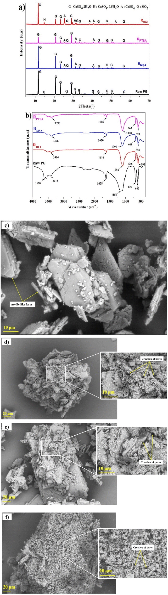
X-ray diffraction analysis was conducted to provide information regarding the metals association in different mineralogical phases in PG and the phase transformations. The X-ray diffraction spectrum of PG samples is displayed in Fig. 1a. The PG dried at 60 °C is mainly composed of dihydrate gypsum (CaSO4·2H2O) as the major phase, followed by the hemihydrate form (CaSO4·0.5H2O), in addition to a low content of quartz (SiO2), which correlates with the previous study using the same PG source.22 The increase of the drying temperature induced the removal of structural water. Heating beyond 200 °C, the transformation of the CaSO4·0.5H2O to the anhydrite form (CaSO4) was observed.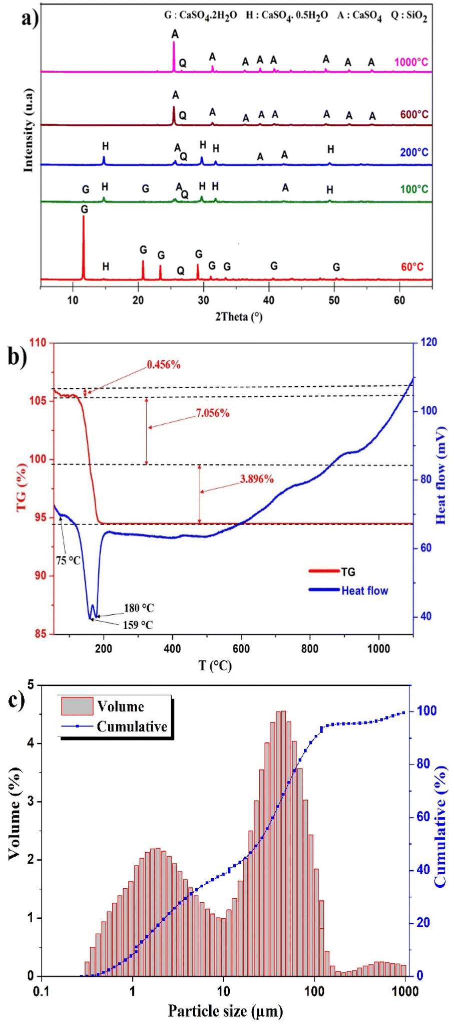 | ||
| Fig. 1 (a) XRD pattern of PG at different temperatures. (b) Thermal behavior of PG. (c) Particle size distribution of PG. | ||
Thermal analysis
The thermal treatment was conducted at different temperatures to assess the evolution of mineral phases and to determine the transition temperatures. Based on TGA/DTA diagram in Fig. 1b, the dehydration of PG takes place in several stages. The first mass lost recorded is 0.456% corresponding to the removal of impregnated water at 75 °C. The most significant mass loss is 7.056% with high endothermic peak at 159 °C which correlates with the removal of structural water of CaSO4·2H2O. This endothermic peak corresponds to the transformation of CaSO4·2H2O to CaSO4·0.5H2O. The formation of CaSO4 takes place at 180 °C with a mass loss of 3.896%.23,24Particle size distribution
The distribution of particle size of PG is presented in Fig. 1c. A tri-modal distribution was observed with particle size ranging from 0.28–955 μm. The most abundant population is centered on 45.7 μm and limited between 10 and 208 μm. The diameters D10, D50, and D90 are 1.11, 23.30 and 71.75 μm, respectively.Effect of lixiviants concentration
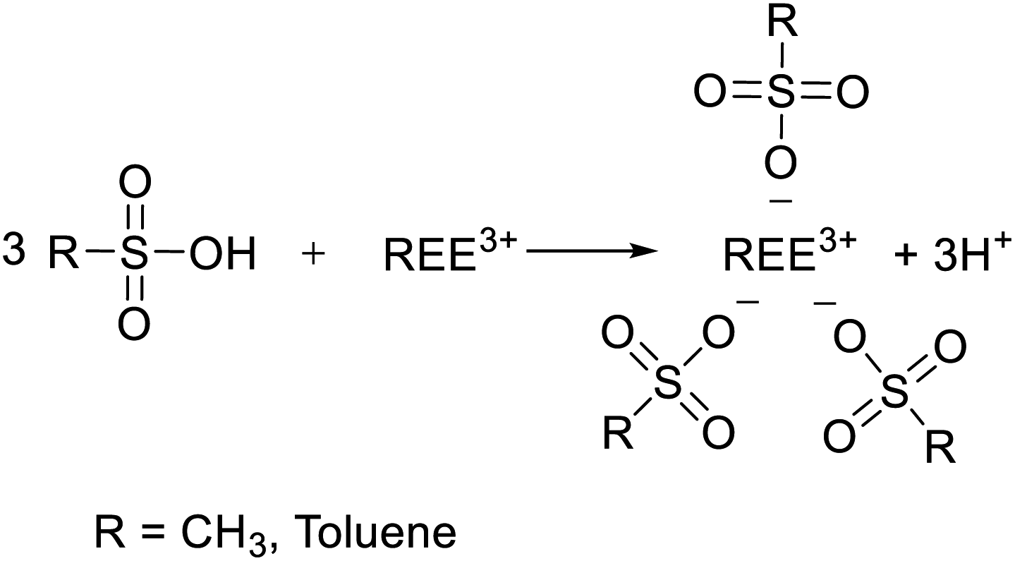
To determine the optimal conditions for the leaching of REEs and metals impurities from PG, three lixiviants (MSA, PTSA and HCl) were used at different concentrations. The results of the leaching as a function of different MSA concentrations are shown in Fig. 2a. It can be observed that the overall behavior of the leaching system is governed by the increase of the acidity. The leaching efficiency of REEs achieved its maximum value of 78% at 3 M of MSA. For individual REEs (Table 2), the leaching efficiency of the major REEs reached 84, 69, 74 and 71% for Y, La, Ce and Nd, respectively. This fact could be explained by the high stability of the formed REEs methanesulfonates complexes during the leaching process as described by eqn (3). Regarding the leaching of metals impurities, MSA promotes the leaching of metals impurities such as Na, Al, Fe, Mg and K with leaching efficiencies of 98, 92, 90, 86 and 81%, respectively at 3 M. On the other hand, the leaching efficiencies of Ca, Ba and Sr were 51, 45 and 47%, respectively. These results could be explained by the high solubility of their corresponding methanesulfonates.25 In addition, other phenomena could control the release of REEs and metals impurities including the recrystallization during the leaching as reported by Cánovas et al.6
 | (3) |
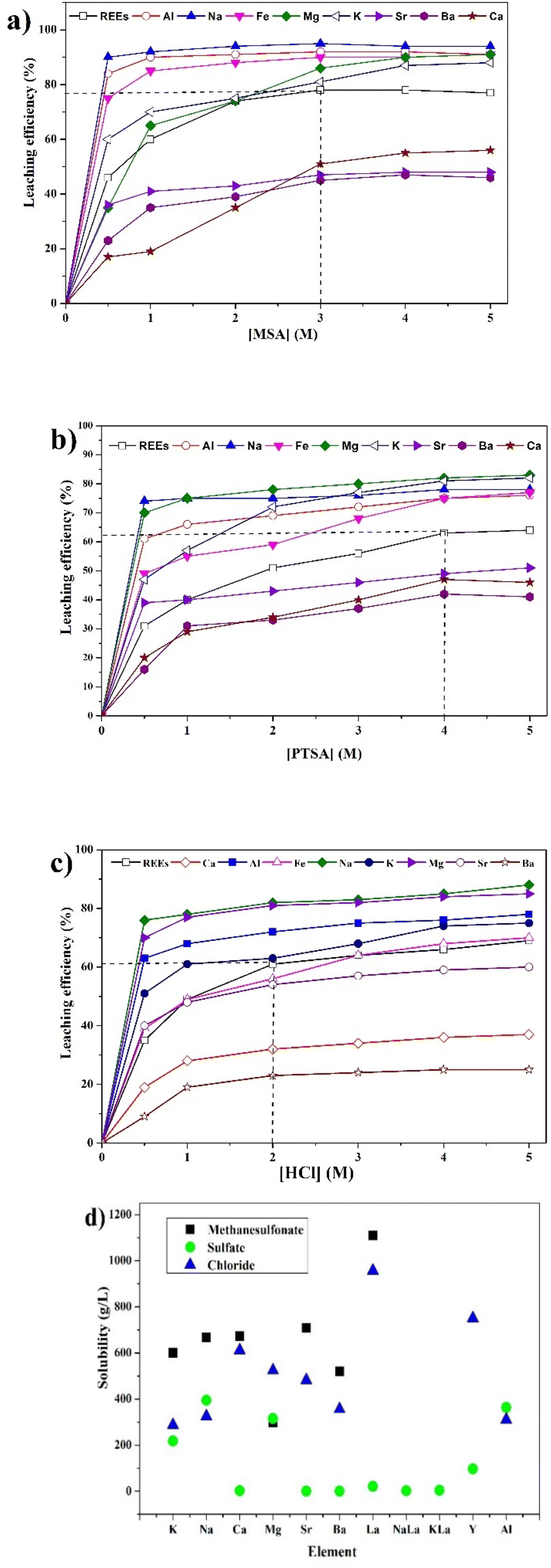 | ||
| Fig. 2 Effect of concentration of (a) MSA, (b) PTSA and (c) HCl on the leaching efficiency of REEs and metals impurities (operating conditions: S/L = 1/8, 120 min, 25 °C and 500 rpm). (d) Literature solubilities of different REEs and metals impurities compounds.11,30–34 | ||
| Element | Content in the PG residue (ppm) | Leaching efficiency (%) | ||||
|---|---|---|---|---|---|---|
| MSA (3 M) | PTSA (4 M) | HCl (2 M) | MSA (3 M) | PTSA (4 M) | HCl (2 M) | |
| Sc | 0.43 | 0.56 | 0.54 | 59 | 42 | 49 |
| Y | 33.56 | 73.96 | 78.02 | 84 | 62 | 63 |
| La | 26.66 | 35.01 | 35.9 | 69 | 56 | 58 |
| Ce | 19.51 | 25.88 | 30.03 | 74 | 62 | 59 |
| Pr | 5.56 | 7.10 | 7.71 | 75 | 65 | 65 |
| Nd | 24.08 | 31.02 | 34.02 | 71 | 59 | 58 |
| Sm | 0.76 | 4.97 | 6.31 | 94 | 58 | 51 |
| Eu | 1.8 | 1.53 | 2.11 | 66 | 68 | 60 |
| Gd | 1.24 | 5.10 | 8.1 | 94 | 75 | 63 |
| Tb | 1.4 | 3.01 | 1.59 | 66 | 20 | 61 |
| Dy | 5.1 | 4.11 | 5.04 | 72 | 75 | 72 |
| Ho | 1.15 | 0.98 | 2.26 | 82 | 83 | 64 |
| Er | 3.43 | 3.62 | 3.57 | 74 | 70 | 73 |
| Tm | 0.42 | 0.70 | 0.85 | 83 | 69 | 66 |
| Yb | 2.43 | 3.02 | 3.38 | 77 | 68 | 67 |
| Lu | 0.34 | 0.30 | 0.66 | 85 | 85 | 70 |
| REEs | 127.87 | 200.87 | 220.09 | 78 | 62 | 62 |
The effect of PTSA concentration on the leaching efficiency of REEs and metals impurities is shown in Fig. 2b. As with the MSA, a gradual increase in the leaching efficiency of REEs was observed by increasing PTSA concentration. The maximum leaching efficiency of REEs was reached at 4 M to be 63%, where the major REEs (Y, La, Ce and Nd) were leached with efficiencies of 52, 56, 62 and 59%, respectively (Table 2). The process could be described by the complexation reaction of REEs in a similar way to that of MSA (eqn (3)). Both acids have similar acidity (pKa of MSA and PTSA are −2.6 and −2.8, respectively).26 Hence, the low leaching efficiency obtained with PTSA compared to MSA could be due to the steric hindrance caused by the aromatic groups. These factors have also been highlighted for other REEs leaching studies using organic acids.27,28 For instance, the van der Waals volume (Vvdw) of PTSA is 143.36 Å3 which is greater than that of MSA (70.74 Å3).26 This fact could reduce the stability of the formed REEs p-toluenesulfonates complexes. At a concentration of 0.5 M, PTSA could be selective for metals impurities including Al, Mg, Na, Fe and K with leaching efficiencies of 61, 70, 74, 49 and 47% respectively, while only 31% of leaching efficiency of REEs was achieved. Consequently, the treatment with low PTSA concentration (0.5 M) could be regarded as a pre-treatment to reduce the amount of impurities before performing the leaching of REEs at the optimal acid concentration (4 M).
For the case of HCl, the leaching efficiency of REEs and metals impurities is considerably affected by the increase in HCl concentration (Fig. 2c). At low acid concentration, the leaching efficiency reached only the value of 34% for REEs. On the other hand, high acid concentration promotes the leaching of REEs to reach an approximate plateau of 62% at 2 M. Beyond this value, slight increase in the leaching efficiency was observed. Therefore, 2 M was chosen as the optimal HCl concentration. In terms of individual REEs, the obtained values for the major REEs are 63, 58, 59 and 58% for Y, La, Ce and Nd, respectively. These values are comparable to the ones obtained for PTSA (Table 2). The leaching process of REEs using HCl could be described according to eqn (4), considering the presence of REEs in isomorphous substitution of calcium in CaSO4·2H2O lattice.29
| REE2(SO4)3 (s) + 6HCl (aq) → 2REECl3 (aq) + 3H2SO4 (aq) | (4) |
The metals impurities including Al, Fe, Na, K and Mg were leached out with leaching efficiencies of 72, 56, 82, 63 and 81%, respectively at 2 M, which may be due to the high solubility of their corresponding sulfate forms. Meanwhile, low leaching efficiencies were achieved for Sr, Ca, and Ba (54, 32 and 23%, respectively), which could be attributed to the low solubility of their sulfate forms in PG.
The comparison between different leaching agents showed that MSA is the most efficient lixiviant for REEs, followed by PTSA and HCl. The high performance of MSA could be explained by the large solubility of REEs methanesulfonate as illustrated in Fig. 2d. The formed complexes of REEs methanesulfonates are more stable in comparison with PTSA complexes which may be due to the steric hindrance caused by the aromatic groups. In addition, the existence of REEs as double sulfate with the remaining sodium and potassium could also reduce the release of REEs since these compounds have low solubility.30,31
Effect of solid/liquid ratio
The leaching efficiency of REEs and metals impurities was studied at different S/L ratios to optimize the acid volumes required for the leaching. The increase in acid volume significantly increases the leaching efficiency since it provides better suspension of the solid which enhances the phases contact at the liquid boundary layer.35 Fig. S2a† displays the effect of S/L ratio using MSA. At 1/4, 57% of the leaching efficiency of REEs was reached. For metals impurities, the obtained leaching efficiencies were 54% for Al, 80% for Na, 61% for K, 46% for Mg and 38% for Fe, while low leaching efficiencies were obtained for Ca, Ba and Sr (10, 13 and 27%, respectively). At high MSA volume (1/12), the leaching efficiency of REEs reached 76% which is not very far from the obtained value at 1/8 (74%). Furthermore, 1/8 could be regarded as the optimal S/L ratio for the leaching using MSA. Similar behavior was also noticed in the case of PTSA (Fig. S2b†) for REEs and metals impurities with low leaching efficiencies compared to the case of MSA.The leaching using HCl at S/L of 1/4 provides low leaching efficiency for both REEs and metals impurities as shown in Fig. S2c† (e.g., 33% for REEs, 28% for Al, 17% for Na, 13% for Fe, 9% for Mg). At 1/8, 62% of leaching efficiency of REEs was obtained with other metals impurities including Al, Na, Fe and Mg with leaching efficiencies of 72, 82, 56 and 82%, respectively. Thus, the S/L ratio of 1/8 could be considered as the optimal ratio, not only for the high leaching efficiency obtained for REEs, but also for reducing the high consumption of acid solution.10
Effect of temperature
The effect of temperature was studied in the range of 25–80 °C under constant acid concentration of 2 M and S/L ratio of 1/8 for 120 min. As shown in Fig. S3a,† the leaching efficiency is slightly influenced by the increase of temperature for MSA. The observed increase in the leaching efficiency was only 6% for REEs in the studied range of temperature. Similar trend was also found for HCl with an increase of over 8% of leaching efficiency of REEs (Fig. S3c†). This fact could be attributed to the low solubility of REEs sulfate at high temperature.36 For the case of metals impurities, the leaching efficiency using MSA increased by 17% for Ca, and 3% for Sr and Ba. On the other hand, the leaching efficiency using HCl is notably increased by 24% for Ba, 13% for K, 12% for Sr and Ca, 10% for Al and Mg, 6% for Na and 7% for Fe in the studied range of temperature.The effect of temperature using PTSA as lixiviant is illustrated in Fig. S3b.† In this case, the leaching efficiency of REEs is enhanced to 55% at temperature up to 40 °C and then moderately decreased to 53% at 80 °C. Comparable behavior was also observed for the metals impurities, which could be partially attributed to the low stability of the formed p-toluenesulfonate complexes at high temperatures up to 80 °C.
Effect of PG solubility
The effect of PG solubility on the leaching of REEs using different lixiviants was studied. Fig. 3a displays the solubility results as a function of different acids concentrations, showing that the leaching is strongly affected by the solubility of PG. The behavior of PG solubility with acid concentration considerably correlates with the leaching efficiency of REEs, which supports the incorporation of the major part of REEs inside the gypsum lattice.37 The increase follows the order of HCl > MSA > PTSA with maximum solubility values of 31.06, 19.93 and 15.62 g L−1, respectively at 4 M. Furthermore, MSA provides high leaching efficiency with low PG solubility, which makes it more selective compared to HCl and PTSA.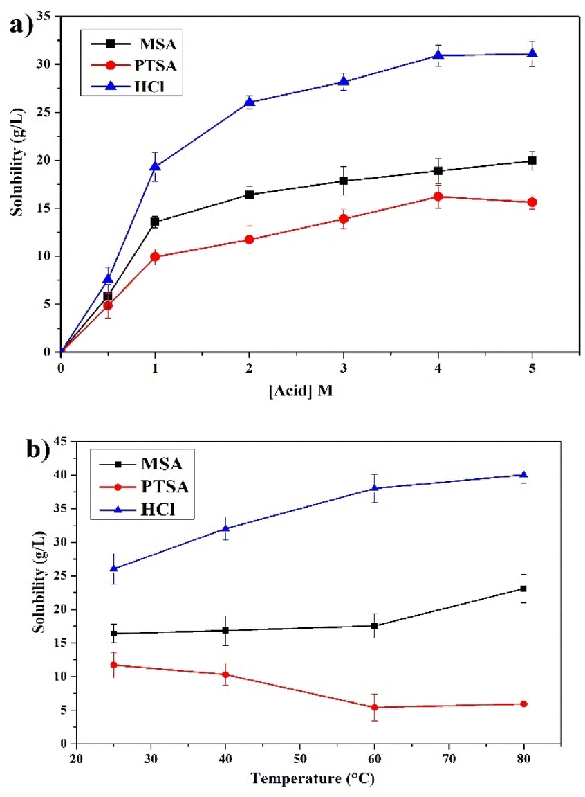 | ||
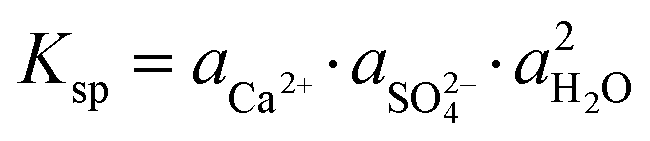
| Fig. 3 Solubility results as a function of (a) acid concentration and (b) temperature. | ||
The effect of temperature on the solubility of PG in the range of 25–80 °C is provided in Fig. 3b. The solubility of PG in MSA and HCl is slightly increased which correlates with the leaching behavior of REEs previously discussed.38,39 On the other hand, the solubility of PG using PTSA is decreased to a certain extent as the temperature increased up to 80 °C, which could be related to the low stability of calcium p-toluenesulfonate complex at elevated temperature.
Characterization of the leaching residues
The X-ray diffraction analysis of PG before and after leaching with different lixiviants is provided in Fig. 4a. The leaching process induced the dehydration of CaSO4·2H2O to CaSO4, which is well-observed in the peaks at 25.45, 31.34 and 40.74° in different residues. This transformation could promote the leaching of REEs due to the high solubility of CaSO4 over CaSO4·2H2O at ambient temperature.40 The dissociation reaction and the solubility product (Ksp) of CaSO4·2H2O in water could be described according to eqn (5) and (6).| CaSO4·2H2O (s) → Ca2+ (aq) + SO2−4 (aq) + 2H2O (l) | (5) |
 | (6) |
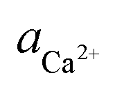 ,
,  and aH2O denote the activity of Ca2+, SO2−4 and H2O, respectively. The formation of CaSO4 during the leaching increased the solubility of PG since the Ksp of CaSO4 (4.93 × 10⁻⁵) is greater than that of CaSO4·2H2O (3.14 × 10⁻⁵) in water at ambient temperature.38,39 Once the solubility limit of PG is reached, the REEs become inaccessible for the lixiviant and will require destroying the PG lattice, which will generate REEs solutions highly loaded with calcium and sulfate.
 | ||
| Fig. 4 (a) XRD and (b) FTIR spectrums of PG before and after leaching. SEM observation of (c) raw PG, (d) residue after leaching using MSA, (e) residue after leaching using PTSA and (f) residue after leaching using HCl (operating conditions: 2 M, 1/8, 120 min, 25 °C and 500 rpm). | ||
The infrared spectrums of PG before and after leaching using MSA, PTSA and HCl are provided in Fig. 4b. Intense bands of sulfate are detected in the region of 1200–1100 cm−1 attributed to the asymmetric stretching vibrational modes ν3. The other bands recorded in the region 700–600 cm−1 corresponds to the bending vibrational mode ν4. On the other hand, less intense bands were detected in the regions of 3600–3200 and 1700–1600 cm−1 which are attributed respectively to the bending vibrational modes and stretching vibrational modes of water.41,42 The bands in the region of 3600–3200 cm−1 could be also assigned for M–OH.43 The absence of any bands related to MSA and PTSA molecules could confirm the high solubility of the formed complexes of REEs and metals impurities.
The morphological investigation of PG is illustrated in Fig. 4c. As it can be observed, the PG particles are presented in a needle-like form with a homogeneous piling arrangement. After leaching, high corrosion of the surface was observed in different residues (Fig. 4d–f) with creation of remarkable cracks and pores on the surface, which indicates the migration of acid solutions inside the particles of PG. The shape of PG particles after leaching using MSA (Fig. 4d) and PTSA (Fig. 4e) is nearly conserved which may support the low solubility obtained and the selectivity of these lixiviants over PG matrix. However, the leaching using HCl (Fig. 4f) induces considerable changes in the shape of PG particles, which may support the high solubility values previously obtained.
Elemental color mapping provided in Fig. 5 shows the presence of the major REEs including Y, La and Ce in raw PG. The accumulation of Y can be clearly observed in Fig. 5a. After leaching, the accumulation of the three elements is considerably reduced.
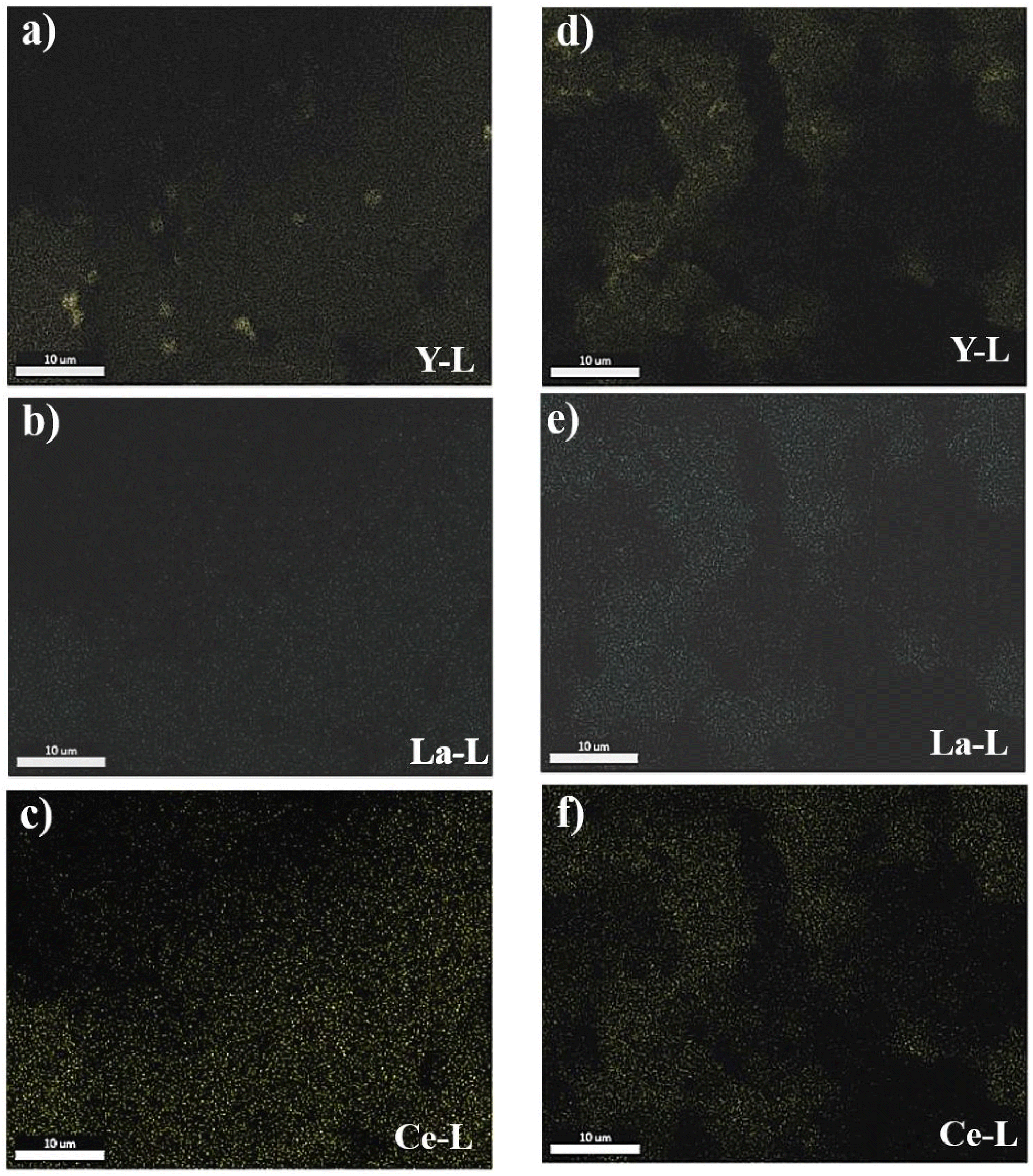 | ||
| Fig. 5 Elemental color mapping of the major REEs in raw PG (from a to c) and in PG residue of MSA under optimal conditions (from d to f). | ||
Kinetics and mechanisms of leaching
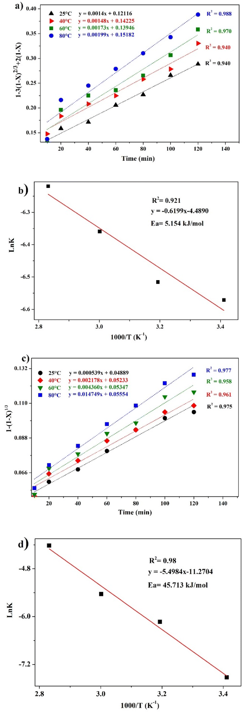
The leaching reaction is usually regarded as a heterogeneous reaction that occurs at the interface between the solid and the lixiviant. The reaction generally takes place in several stages including liquid diffusion, chemical reaction and diffusion through the product layer as described elsewhere.44 Fig. 6a shows the evolution of the leaching efficiency of REEs over time using MSA, PTSA and HCl. It can be observed that the process is kinetically fast in the early stage of the leaching (e.g., 55, 52 and 45% of leaching efficiency was achieved only in 2 min respectively for MSA, PTSA and HCl). In a prolonged reaction time, the leaching efficiency of REEs is promoted to over 76% for MSA and 62% for PTSA and HCl at 120 min. Therefore, 120 min could be regarded as the optimal time for a complete leaching reaction of REEs since the leaching efficiency is slightly increased beyond this time.45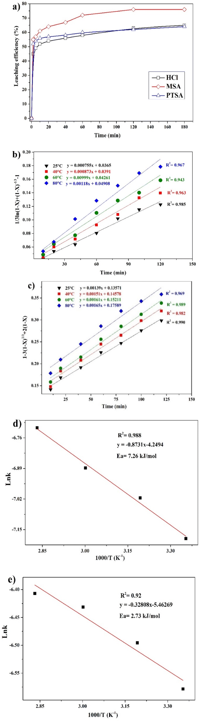 | ||
| Fig. 6 (a) Effect of leaching time on the leaching efficiency of REEs using MSA, PTSA and HCl. (b) Plot of interfacial transfer & diffusion-controlled model in the temperature range of 25–80 °C. (c) Plot of product layer diffusion-controlled model in the temperature range of 25–80 °C. Plot of the linear form of Arrhenius equation for (d) interfacial transfer & diffusion-controlled model and (e) product layer diffusion-controlled model in the temperature range of 25–80 °C. | ||
The modeling of the leaching kinetics could be performed using several approaches such as the shrinking core theory to determine the rate-determining stage and to describe the kinetics behavior of the leaching of REEs. This could be done by considering the PG particle as spherical with a constant size (eqn (7)–(10)).35
Chemical reaction-controlled model:
| 1 − (1 − X)1/3 = kct | (7) |
Inner diffusion-controlled model:
 | (8) |
Product layer diffusion-controlled model:
| 1 − 3(1 − X)2/3 + 2(1 − X) = kpt | (9) |
Interfacial transfer & diffusion-controlled model:
 | (10) |
Different kinetics models were applied to fit the experimental results of REEs leaching using MSA, PTSA and HCl at different temperatures (25–80 °C). The activation energy (Ea) was also determined in each case by plotting the linear form of Arrhenius equation at different temperatures. For MSA, the plot of the interfacial transfer & diffusion-controlled model is shown in Fig. 6b. The model fitted well the experimental results at all temperatures with correlation coefficients above 0.94. The obtained Ea required for the process was calculated to be 7.26 kJ mol−1 (Fig. 6d). However, the obtained values of Ea in previous studies present a large variation. For instance, Li et al.46 found a value of 41.65 kJ mol−1 in the temperature range of 75–90 °C, which usually corresponds to a very sensitive process to temperature such as the chemically controlled process.47 In another study reported by Huang et al.,48 it was found that the activation energy for the process is 26.95 kJ mol−1 in the temperature range of 30–90 °C, which falls in the range of a mixed control process according to.47 Furthermore, the low value found in this study is not consistent with the previous values reported for this model. The plot of the product layer diffusion-controlled model provides high correlation coefficients at different temperatures (Fig. 6c). For example, the model presents the highest fitting at low temperature with a correlation coefficient of 0.99. On the other hand, the required Ea calculated for the model at different temperatures was found to be 2.73 kJ mol−1 (Fig. 6e). This low value of Ea is in accordance with the kinetics behavior of the leaching system since it is not very sensitive to the variation of temperature in the range of 25–80 °C.49
According to this model, the leaching is controlled by the diffusion of MSA through the product layer to reach the interface of the unreacted core of PG. Thus, this stage is considered as the rate-determining stage of the leaching.50 The mechanism governing the leaching reaction could be illustrated in Fig. 7. After penetration of MSA molecules through the product layer, the corrosion of the surface by the high acidity induces the creation of pores and cracks promoted by the removal of structural water molecules, which allows the diffusion of MSA inside the unreacted core of PG particle.51
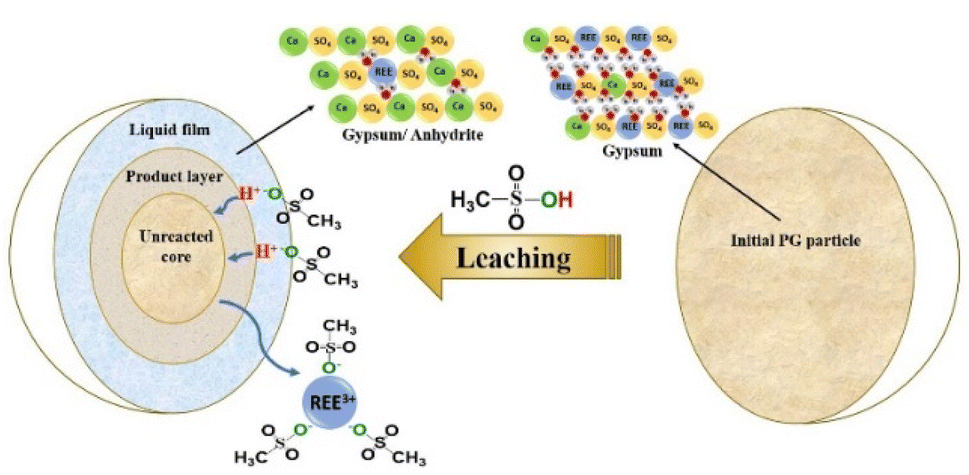 | ||
| Fig. 7 Proposed leaching mechanism of REEs by MSA. | ||
The kinetics behavior for PTSA and HCl is depicted in Fig. 8. The leaching mechanism using PTSA was also found to be governed by the product layer diffusion with high correlation coefficients (Fig. 8a). The activation energy Ea was determined to be 5.154 kJ mol−1 (Fig. 8b). On the other hands, the leaching of REEs using HCl is controlled by the chemical reaction mechanism as shown in Fig. 8c. The obtained value of Ea was 45.713 kJ mol−1 (Fig. 8d), which is in accordance with the usual values found for chemical reaction-controlled model.44
 | ||
| Fig. 8 (a) Plot of the product layer diffusion-controlled model for PTSA in the temperature range of 25–80 °C. (b) Arrhenius plot of the product layer diffusion-controlled model for PTSA in the temperature range of 25–80 °C. (c) Plot of the chemical reaction-controlled model for HCl in the temperature range of 25–80 °C. (d) Arrhenius plot of the chemical reaction-controlled model for HCl in the temperature range of 25–80 °C. | ||
Conclusions
The present study put an emphasis on the development of an environmentally eco-friendly leaching process of REEs from PG using aqueous solutions of MSA. The comparison of this lixiviant with PTSA and HCl showed high leaching efficiency and selectivity with respect to PG matrix. MSA achieved the highest leaching efficiency of 78% with low solubility of PG under the operating conditions of 3 M, S/L ratio of 1/8, 120 min and 25 °C. It is noticeable that the transition of gypsum to the anhydrite promoted the leaching of REEs to some extent. Moreover, the kinetics investigations using shrinking core theory demonstrated the existence of the product layer diffusion-controlled model. The required activation energy for the leaching using MSA was determined to be 2.73 kJ mol−1, which confirms the unsignificant effect of temperature in the studied range. Additionally, the cleaned PG could be a good candidate in building materials applications to achieve zero-waste production in the fertilizer industry. Finally, the present process provides promising outcomes for further development of green and economically feasible process for REEs leaching and PG valorization.Author contributions
J. Ait Brahim: writing – original draft. A. Merroune: writing – original draft. R. Boulif: validation; resources. E. M. Mounir: funding acquisition. R. Beniazza: supervision; conceptualization; review & editing.Conflicts of interest
There are no conflicts to declare.Acknowledgements
The authors acknowledge the financial support of the project provided by Mohammed VI Polytechnic University and OCP Group.References
- B. Zhou, Z. Li and C. Chen, Minerals, 2017, 7, 203 CrossRef.
- N. Dushyantha, N. Batapola, I. M. S. K. Ilankoon, S. Rohitha, R. Premasiri, B. Abeysinghe, N. Ratnayake and K. Dissanayake, Ore Geol. Rev., 2020, 122, 103521 CrossRef.
- S. Al-Thyabat and P. Zhang, Miner. Process. Extr. Metall., 2015, 124, 143–150 CrossRef CAS.
- M. Salem, R. Souissi, F. Souissi, N. Abbes and J. Moutte, Waste Manag., 2019, 83, 46–56 CrossRef CAS PubMed.
- F. Wu, B. Chen, G. Qu, S. Liu, C. Zhao, Y. Ren and X. Liu, J. Environ. Manage., 2022, 311, 114827 CrossRef CAS PubMed.
- C. R. Cánovas, S. Chapron, G. Arrachart and S. Pellet-Rostaing, J. Cleaner Prod., 2019, 219, 225–235 CrossRef.
- H. El-Didamony, H. S. Gado, N. S. Awwad, M. M. Fawzy and M. F. Attallah, J. Hazard. Mater., 2013, 244–245, 596–602 CrossRef CAS PubMed.
- I. Hammas-Nasri, K. Horchani-Naifer, M. Férid and D. Barca, Miner. Eng., 2019, 132, 169–174 CrossRef CAS.
- M. Salo, Miner. Eng., 2020, 155, 106408 CrossRef CAS.
- M. Walawalkar, C. K. Nichol and G. Azimi, Hydrometallurgy, 2016, 166, 195–204 CrossRef CAS.
- F. C. Walsh and C. Ponce de León, Surf. Coat. Technol., 2014, 259, 676–697 CrossRef CAS.
- J. Ahn, J. Wu and J. Lee, Hydrometallurgy, 2019, 187, 54–62 CrossRef CAS.
- J. Wu, J. Ahn and J. Lee, Miner. Process. Extr. Metall. Rev., 2021, 42, 38–45 CrossRef CAS.
- H. C. Erythropel, J. B. Zimmerman, T. M. de Winter, L. Petitjean, F. Melnikov, C. H. Lam, A. W. Lounsbury, K. E. Mellor, N. Z. Janković, Q. Tu, L. N. Pincus, M. M. Falinski, W. Shi, P. Coish, D. L. Plata and P. T. Anastas, Green Chem., 2018, 20, 1929–1961 RSC.
- N. R. Rodriguez, B. Grymonprez and K. Binnemans, Ind. Eng. Chem. Res., 2021, 60, 10319–10326 CrossRef CAS.
- F. Forte, L. Yurramendi, J. L. Aldana, B. Onghena and K. Binnemans, RSC Adv., 2019, 9, 1378–1386 RSC.
- M. Chakrabarty, R. Mukherjee, S. Karmakar and Y. Harigaya, Monatsh. Chem., 2007, 138, 1279–1282 CrossRef CAS.
- H. Li, Z. Han, F. Liu, G. Li, M. Guo, P. Cui, S. Zhou and M. Yu, Faraday Discuss., 2021, 231, 342–355 RSC.
- J. Zhu, N. Jiao, H. Li, G. Xu, H. Zhang and Y. Xu, Bioresour. Technol., 2022, 355, 127300 CrossRef CAS PubMed.
- R. El Zrelli, L. Rabaoui, N. Daghbouj, H. Abda, S. Castet, C. Josse, P. van Beek, M. Souhaut, S. Michel, N. Bejaoui and P. Courjault-Radé, Environ. Sci. Pollut. Res., 2018, 25, 14690–14702 CrossRef CAS PubMed.
- K. Agayr, H. Chanouri, B. Achiou, R. Benhida and K. Khaless, J. Mater. Cycles Waste Manage., 2022, 24, 2015–2029, DOI:10.1007/s10163-022-01461-2.
- A. Lachehab, O. Mertah, A. Kherbeche and H. Hassoune, Mater. Sci. Energy Technol., 2020, 3, 611–625 CAS.
- S. Bouzit, S. Laasri, M. Taha, A. Laghzizil, A. Hajjaji, F. Merli and C. Buratti, Appl. Sci., 2019, 9, 2443 CrossRef CAS.
- A. E. Cadi, A. F. Lanjri, A. Lalilti, N. Chouaibi, A. Asskali and M. Khaddor, J. Mater. Environ. Sci., 2014, 5, 2223–2229 Search PubMed.
- M. D. Gernon, M. Wu, T. Buszta and P. Janney, Green Chem., 1999, 1, 127–140 RSC.
- H. Chen, S.-Y. Han, R.-H. Liu, T.-F. Chen, K.-L. Bi, J.-B. Liang, Y.-H. Deng and C.-Q. Wan, J. Power Sources, 2018, 376, 168–176 CrossRef CAS.
- R. Banerjee, A. Mohanty, S. Chakravarty, S. Chakladar and P. Biswas, Hydrometallurgy, 2021, 201, 105575 CrossRef CAS.
- M. S. Gasser, Z. H. Ismail, E. M. Abu Elgoud, F. Abdel Hai, O. I. Ali and H. F. Aly, J. Hazard. Mater., 2019, 378, 120762 CrossRef CAS PubMed.
- S. Al-Thyabat and P. Zhang, Hydrometallurgy, 2015, 153, 30–37 CrossRef CAS.
- A. Porvali, B. P. Wilson and M. Lundström, Waste Manag., 2018, 71, 381–389 CrossRef CAS PubMed.
- E. P. Lokshin, O. A. Tareeva, K. G. Ivlev and T. G. Kashulina, Russ. J. Appl. Chem., 2005, 78, 105831063 Search PubMed.
- L. Gijsemans, F. Forte, B. Onghena and K. Binnemans, RSC Adv., 2018, 8, 26349–26355 RSC.
- F. H. Spedding and S. Jaffe, J. Am. Chem. Soc., 1954, 76, 882–884 CrossRef CAS.
- E. P. Lokshin, O. A. Tareeva and T. G. Kashulina, Russ. J. Appl. Chem., 2008, 81, 1–7 CrossRef CAS.
- J. Ait Brahim, S. Ait Hak, B. Achiou, R. Boulif, R. Beniazza and R. Benhida, Miner. Eng., 2022, 177, 107351 CrossRef CAS.
- G. Das, M. M. Lencka, A. Eslamimanesh, P. Wang, A. Anderko, R. E. Riman and A. Navrotsky, J. Chem. Thermodyn., 2019, 131, 49–79 CrossRef CAS.
- J. E. Dutrizac, Hydrometallurgy, 2017, 174, 38–46 CrossRef CAS.
- Z. Li and G. P. Demopoulos, Ind. Eng. Chem. Res., 2006, 45, 2914–2922 CrossRef CAS.
- R. H. Moreira, F. S. Queiroga, H. A. Paiva, N. H. Medina, G. Fontana and M. A. Guazzelli, J. Environ. Chem. Eng., 2018, 6, 6664–6668 CrossRef CAS.
- G. Azimi and V. G. Papangelakis, AIChE Annu. Meet., Conf. Proc., 2008, 12 Search PubMed.
- Y. Ennaciri, M. Bettach, A. Cherrat and A. Zegzouti, J. Mater. Environ. Sci., 2016, 7, 19251933 Search PubMed.
- J. L. Bishop, M. D. Lane, M. D. Dyar, S. J. King, A. J. Brown and G. A. Swayze, Am. Mineral., 2014, 99, 2105–2115 CrossRef.
- T. N. Tran, T. V. Anh Pham, M. L. Phung Le, T. P. Thoa Nguyen and V. M. Tran, Adv. Nat. Sci.: Nanosci. Nanotechnol., 2013, 4, 045007 CAS.
- T. Havlík, in Hydrometallurgy, Elsevier, 2008, pp. 184–241 Search PubMed.
- M. Walawalkar, C. K. Nichol and G. Azimi, Ind. Eng. Chem. Res., 2016, 55, 12309–12316 CrossRef CAS.
- M. Li, J. Li, D. Zhang, K. Gao, H. Wang, W. Xu, J. Geng, X. Zhang and X. Ma, J. Rare Earths, 2020, 38, 1019–1029 CrossRef CAS.
- A. Kumari, M. K. Sinha, S. Pramanik and S. K. Sahu, Waste Manag., 2018, 75, 486–498 CrossRef CAS PubMed.
- Y. Huang, Z. Dou, T. Zhang and J. Liu, Hydrometallurgy, 2017, 173, 15–21 CrossRef CAS.
- H.-S. Yoon, C.-J. Kim, K. W. Chung, S.-J. Lee, A.-R. Joe, Y.-H. Shin, S.-I. Lee, S.-J. Yoo and J.-G. Kim, Korean J. Chem. Eng., 2014, 31, 706–711 CrossRef CAS.
- T. Salmi, H. Grénman, J. Wärnå and D. Yu. Murzin, Chem. Eng. Process., 2011, 50, 1076–1084 CrossRef CAS.
- A. Lambert, J. Anawati, M. Walawalkar, J. Tam and G. Azimi, ACS Sustainable Chem. Eng., 2018, 6, 16471–16481 CrossRef CAS.
Footnote |
| † Electronic supplementary information (ESI) available: Additional figures (Fig. S1–S3). See DOI: https://doi.org/10.1039/d2ra04124c |
| This journal is © The Royal Society of Chemistry 2022 |