DOI:
10.1039/D2RA03558H
(Paper)
RSC Adv., 2022,
12, 20946-20955
Synergetic effect of photocatalysis and peroxymonosulfate activated by MFe2O4 (M = Co, Mn, or Zn) for enhanced photocatalytic activity under visible light irradiation†
Received
8th June 2022
, Accepted 9th July 2022
First published on 21st July 2022
Abstract
Nanosized MFe2O4 (M = Co, Mn, or Zn) photocatalysts were synthesized via a simple sol–gel method. MFe2O4 photocatalysts exhibited lower photocatalytic activity for the degradation of levofloxacin hydrochloride under visible light irradiation. For enhancement of photocatalytic activity, MFe2O4 was used to activate peroxymonosulfate and degrade levofloxacin hydrochloride under visible light irradiation. The influences of peroxymonosulfate dosage, levofloxacin hydrochloride concentration, pH value, and temperature on peroxymonosulfate activation to degrade levofloxacin hydrochloride were investigated in detail. The mechanism of activation of peroxymonosulfate by MFe2O4 was proposed and proved by radical quenching experiments, electron spin resonance analysis, X-ray photoelectron spectroscopy, electrochemical impedance spectroscopy, and transient photocurrent responses. The combined activation effects of photogenerated e−/h+ and transition metals on peroxymonosulfate to produce sulfate radical clearly enhanced the degradation efficiency.
1 Introduction
With the rapid development of aquaculture, antibiotics are widely used to treat infectious diseases of fish. However, remnant antibiotic drugs have the potential to harm people and the environment.1,2 Levofloxacin hydrochloride is a quinolone with antibacterial activities.3,4 Residual levofloxacin hydrochloride in water can increase the resistance of microbes, which is harmful to human health and safety.5–7 Hence, it is important to develop a method to remove the levofloxacin hydrochloride in water.
Photocatalytic technology is an advanced oxidation method that is an outstanding achievement for water treatment because it is inexpensive and produces no secondary pollution.8,9 The photocatalytic reaction produces free radicals in a chain reaction until the end products of degradation are CO2 and H2O. For wastewater treatment, there is higher research value in the photocatalytic reaction for the treatment of pollutants because of its low selectivity, rapid reaction process, and simple operation compared with conventional oxidation technology.10
Fe-based heterogeneous catalysts have been widely explored and studied because they are environmentally friendly, inexpensive, and non-toxic compared to other metals. In addition, spinel ferrite nanoparticles are magnetic semiconductors and have been used for activating peroxymonosulfate (PMS).11–13 Ferrite nanoparticles are a magnetic nanomaterial that can be simply recycled from solution by applying an external magnetic field. The presence of ferrite magnetic nanoparticles greatly increases the efficiency of pollutant removal. These materials directly activate PMS to produce sulfate radical (SO4˙−). Previous conductivity measurements determined that the band gaps of CoFe2O4, MnFe2O4, and ZnFe2O4 were in the range of 0.5–0.6 eV.14–16 This indicates that CoFe2O4, MnFe2O4, and ZnFe2O4 can be considered as narrow band gap semiconductors that can absorb a greater amount of visible light, and their narrow band gaps allow sunlight to be fully utilized. Furthermore, CoFe2O4, MnFe2O4, and ZnFe2O4 nanoparticles increase the efficiency of removal and can be simply recycled from a heterogeneous suspension using an external magnetic field after the completion of photocatalytic reactions. Thus, secondary pollution created by the disposal of photocatalysts would not be produced.17–20
In this work, nanosized MFe2O4 (M = Co, Mn, or Zn) photocatalysts were synthesized by a sol–gel method. To further increase the degradation efficiency of levofloxacin hydrochloride, MFe2O4 photocatalysts were used to activate PMS under visible light irradiation. In addition to photogenerated e−/h+, Fe, Co, Mn, and Zn can also activate PMS to produce SO4˙−, and thus, the combined activation effects of photogenerated e−/h+ and transition metals on PMS to produce SO4˙− can clearly enhance the degradation efficiency. The influences of PMS dosage, pH value, levofloxacin hydrochloride concentration, and temperature on PMS activation were investigated in detail. Moreover, the degradation mechanisms used by MFe2O4 photocatalysts to activate PMS were systematically studied.
2 Experimental
2.1 Materials
Levofloxacin hydrochloride (LVX) of analytical reagent grade quality was used without further purification. Potassium peroxymonosulfate (2KHSO5·3KHSO4·K2SO4, Oxone®) (PMS) was purchased from Sigma-Aldrich. Other chemicals were analytical or reagent grade commercial products. All solutions were prepared with deionized water.
2.2 Preparation of MFe2O3
First, 4 mmol Fe(NO3)3·9H2O, 2 mmol Co(NO3)2·6H2O, and 12 mmol citric acid were dissolved in a mixture of deionized water (10 mL) and ethanol (20 mL), which was maintained at 70 °C until it entered into the gel state. The gel was dried at 80 °C until it formed a xerogel, which was calcined in a muffle furnace at 550 °C for 5 hours with a heating rate of 5 °C min−1 to obtain CoFe2O4 powder. The ZnFe2O4 sample was prepared using the same protocol. However, the MnFe2O4 sample was calcined at 400 °C for 5 hours, although the other preparation steps were carried out in the same manner as those for CoFe2O4.
2.3 Characterizations
The UV-Vis diffuse reflectance spectra (UV-Vis DRS) of the samples were obtained on a UV-Vis spectrophotometer (Lambda 950, PerkinElmer) using an integrating sphere accessory, and BaSO4 was used as a reflectance standard. X-ray diffraction (XRD) experiments were carried out using a Rigaku D/MAX 2500 diffractometer with Cu Kα radiation. The size and morphologies of MFe2O4 were characterized with the aid of a JSM-7000F field emission scanning electron microscope. Fourier transform infrared (FT-IR) spectroscopy was recorded on a Thermo Nicolet iS5 spectrometer with a KBr disk. The magnetic property was measured at room temperature with the Quantum Design MPMS-SQUID VSM-094. X-ray photoelectron spectroscopy (XPS) measurements were performed using a Kratos AXIS ULTRA DLD. Electron paramagnetic resonance (EPR) measurements of spin-trapped radicals with spin-trap reagent 5,5-dimethyl-1-pirroline-N-oxide (DMPO) (Sigma-Aldrich) were carried out at room temperature with a Bruker A300 spectrometer equipped with a high-pressure mercury lamp as the irradiation source. To minimize experimental errors, the same type of quartz capillary tube was used for all EPR measurements. An EPR spectrometer was coupled to a computer for data acquisition and instrument control.
2.4 Photo-electrochemical properties
Photo-electrochemical measurements were carried out using a conventional three-electrode, single-compartment glass cell fitted with a synthesized quartz window using a potentiostat. The quartz electrolytic cell was filled with 0.1 M Na2SO4. A total of 10 mg of synthesized MFe2O4 was dropped onto the ITO glass (2.0 × 4.0 cm), which was used as a working electrode for electrochemical impedance spectroscopy (EIS) and chronoamperometry experiments. A 500 W xenon lamp (Institute of Electric Light Source, Beijing) was used as the light source for the visible light irradiation in the photoelectrochemical analyses. A 420 nm cutoff filter was placed onto the window face of the cell to ensure the desired irradiation conditions. The counter and reference electrodes were a platinum black wire and Ag/AgCl electrode, respectively. The photoelectrochemical experiment was performed using an electrochemical system (Shanghai Chenhua-CHI660e).
2.5 Photocatalytic oxidative degradation
The photocatalytic activities of MFe2O4 were evaluated by LVX decomposition under visible light irradiation. In the case of visible light irradiation, a 300 W halogen lamp (Philips Plusline, Shanghai) was focused through a window. A 420 nm cutoff filter was placed onto the window face of the cell to ensure the desired irradiation conditions. The average light intensity was 65 mW cm−2. The radiant flux was measured with a power meter (Beijing Normal University, Beijing).
A cylindrical double-layer glass photochemical reactor with internal diameter 70 mm, external diameter 80 mm, and height 100 mm was utilized for the photocatalysis reaction. A distance of approximately 17 cm between the lamp and reactor was maintained. Running water was piped into the layer to maintain a constant temperature.
The photocatalytic degradation of LVX in aqueous solution was studied using MFe2O4 as the photocatalyst at room temperature and under normal atmospheric pressure. MFe2O4 (50 mg) and 100 mL LVX (10 mg L−1) aqueous solution were added to the reactor, and then stirred with a magnetic stirrer prior to irradiation by a halogen lamp at room temperature. Prior to irradiation, the solution was incubated in the dark for 30 min to ensure equilibrium of the working solution. After the reaction, the sample solution was centrifuged to remove MFe2O4, and the solution obtained this way was extracted into a quartz cell. The absorbance of the samples was measured using quartz cells every 10 min.
For the photocatalytic test of MFe2O4 activating PMS, MFe2O4 was dispersed into LVX solution and magnetically stirred in the dark for 30 min to ensure adsorption–desorption equilibrium. A certain amount of PMS was added to the reactor, and the concentration of LVX solution was monitored by measuring the absorbance as the initial concentration as C0. Then, the lamp was turned on to initiate the photodegradation reaction. After five min, 3 mL of the solution was removed and filtered using a 0.22 mm membrane to separate the catalyst powders from the solution, where the instantaneous concentration of LVX was measured every 10 min as C.
3 Results and discussion
3.1 Controlling the synthesis of MFe2O4
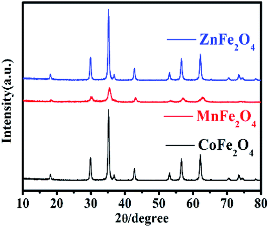
The XRD patterns were used to study the crystal structure of MFe2O4. The XRD patterns of the phase characteristics and crystalline structure information for MFe2O4 are shown in Fig. 1. For CoFe2O4 nanoparticles, the diffraction peaks of all the samples were easily indexed as CoFe2O4, which were in agreement with the standard card (JCPDS card number: 79-1744, R![[3 with combining macron]](https://www.rsc.org/images/entities/char_0033_0304.gif) m (166) Space Group) with major peaks at 2θ = 18.28°, 30.08°, 35.43°, 37.06°, 43.05°, 56.04°, and 62.52° corresponding to the diffractions of (003), (104), (113), (006), (024), (125), and (119), respectively. For MnFe2O4, the diffraction peaks of all the samples were easily indexed as MnFe2O4, which were in agreement with the standard card (JCPDS card number: 73-1964, Fdm (227) Space Group) with major peaks at 2θ = 18.03°, 29.66°, 34.93°, 42.44°, 56.10°, and 61.59° corresponding to (111), (220), (311), (400), (333), and (440), respectively. For ZnFe2O4, the diffraction peaks of all the samples were easily indexed as ZnFe2O4, which were in agreement with the standard card (JCPDS card number: 73–1963, Fdm (227) Space Group) with major peaks at 2θ = 18.38°, 30.24°, 35.63°, 43.30°, 57.28°, and 62.91° corresponding to (111), (220), (311), (400), (511), and (440), respectively.
m (166) Space Group) with major peaks at 2θ = 18.28°, 30.08°, 35.43°, 37.06°, 43.05°, 56.04°, and 62.52° corresponding to the diffractions of (003), (104), (113), (006), (024), (125), and (119), respectively. For MnFe2O4, the diffraction peaks of all the samples were easily indexed as MnFe2O4, which were in agreement with the standard card (JCPDS card number: 73-1964, Fdm (227) Space Group) with major peaks at 2θ = 18.03°, 29.66°, 34.93°, 42.44°, 56.10°, and 61.59° corresponding to (111), (220), (311), (400), (333), and (440), respectively. For ZnFe2O4, the diffraction peaks of all the samples were easily indexed as ZnFe2O4, which were in agreement with the standard card (JCPDS card number: 73–1963, Fdm (227) Space Group) with major peaks at 2θ = 18.38°, 30.24°, 35.63°, 43.30°, 57.28°, and 62.91° corresponding to (111), (220), (311), (400), (511), and (440), respectively.
 |
| | Fig. 1 The XRD pattern of MFe2O4 prepared by a sol–gel method. | |
The microstructures of MFe2O4 were observed by scanning electron microscopy (SEM), as shown in Fig. 2a–d. The CoFe2O4, MnFe2O4, and ZnFe2O4 nanoparticles were agglomerated together. The CoFe2O4 result (Fig. 2a and b) shows agglomerated nanoparticles 10–20 nm in size. The MnFe2O4 (Fig. 2c) particle size was approximately 30 nm, and the ZnFe2O4 nanoparticles (Fig. 2d) were 20–30 nm in size.
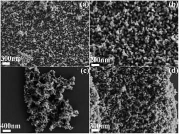 |
| | Fig. 2 SEM images of MFe2O4: (a) CoFe2O4, (b) CoFe2O4, (c) MnFe2O4, and (d) ZnFe2O4. | |
3.2 FT-IR spectrum and the optical properties of MFe2O4
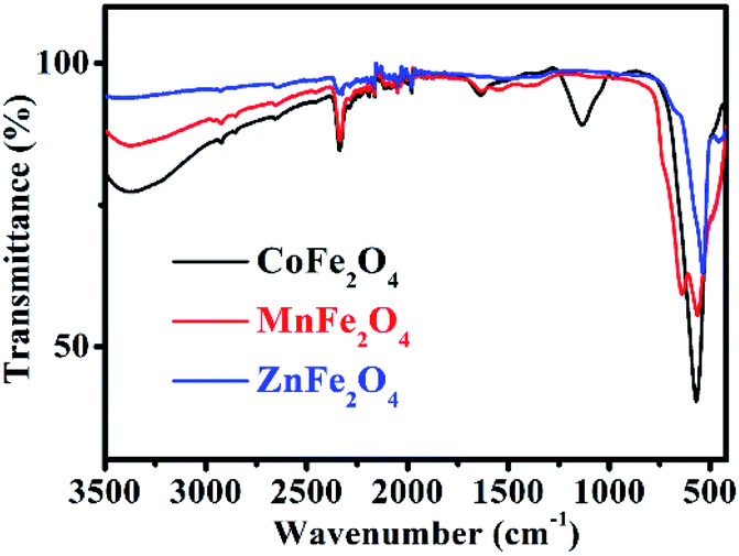
The FT-IR spectrum of MFe2O4 is shown in Fig. 3. For CoFe2O4, the absorption band at 1113 cm−1 is characteristic of the cobalt ferrite system, and this may be due to the residual FeOOH. The absorption bands present at approximately 568 cm−1 were due to the stretching vibrations of metal oxide in the octahedral group complex Co(II)–O2− and Fe(III)–O2− tetrahedral group complex of the cobalt ferrite phase, respectively, which proves the existence of spinel ferrite.21 The peaks at 1635 cm−1, 2336 cm−1, and 3373 cm−1 were attributed to the vibrational stretching of the O–H bond of H2O due to the bending of the absorbed water molecules.22 For MnFe2O4, the characteristic peaks at approximately 563 cm−1 and 637 cm−1 corresponded to the formation of Mn–O and Fe–O bonds at the octahedral sites of spinel-type compounds.23 For ZnFe2O4, the characteristic absorption peaks at 537 cm−1 and 452 cm−1 denoted the stretching vibration of the Fe–O and Zn–O bonds, indicating the existence of ZnFe2O4.24
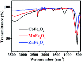 |
| | Fig. 3 FT-IR spectra of MFe2O4. | |
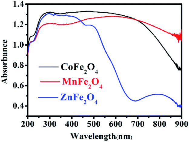
UV-Vis diffuse reflectance spectroscopy (DRS) was used to research the optical property of the photocatalysts.25 There was strong absorption for CoFe2O4 and MnFe2O4 in the range of 200–900 nm, and strong absorption for ZnFe2O4 in the range of 200–600 nm, as shown in Fig. 4. Therefore, the visible light was efficiently utilized. The steep shape of the spectra indicated that the visible light absorption was not caused by a transition from the impurity level, but rather, was caused by the band-gap transition.26
 |
| | Fig. 4 UV-Vis diffuse reflectance spectra of MFe2O4. | |
3.3 Magnetic properties of MFe2O4 photocatalysts
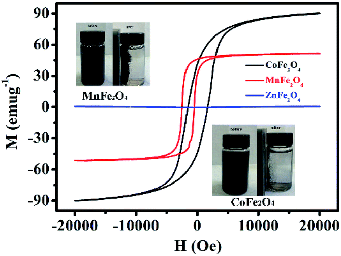
Fig. 5 shows the H–M hysteresis loop of MFe2O4 samples prepared by a sol–gel method. There were excellent magnetic properties for CoFe2O4 and MnFe2O4, and the values of specific magnetization (Ms) were 90.8 and 52.3 emu g−1, which thus indicated superparamagnetism. By comparison, ZnFe2O4 was 5.02 emu g−1, which was much less than that of CoFe2O4 and MnFe2O4. Difficulty in recycling of the photocatalyst could significantly hinder its extensive application in wastewater treatment. Thus, by taking advantage of the magnetic properties of CoFe2O4 and MnFe2O4, the photocatalysts can be easily recycled for multiple usages. The inset of Fig. 5 shows that CoFe2O4 and MnFe2O4 can be readily dispersed in water to form a stable solution. In addition, the photocatalyst rapidly responds to the external magnet because of its excellent magnetic properties. After magnetic separation, most of the CoFe2O4 and MnFe2O4 photocatalyst particles were drawn to the bottle sidewall. As a result, this dispersion and separation process can be repeatedly applied with CoFe2O4 and MnFe2O4 using an external magnetic field, which is convenient for their reusability in water treatment and minimizes any secondary pollution.
 |
| | Fig. 5 Magnetic hysteresis loops of MFe2O4. The inset shows photos of well-dispersed MFe2O4 in water and magnetic separation of MFe2O4. | |
3.4 Photocatalytic properties of MFe2O4
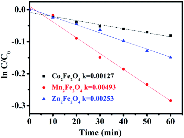
The photocatalytic activity of MFe2O4 was estimated by the removal of LVX. To further depict the photocatalytic reaction, the photocatalytic degradation process was also fitted to pseudo first-order kinetics, and the value of the rate constant k is equal to the corresponding slope of the fitting line, as shown in Fig. 6. The first-order linear relationship was revealed by the plots of ln(C/C0) vs. irradiation time (t), where C denotes the concentration of LVX at irradiation time t, and C0 denotes the concentration during the adsorption equilibrium of the photocatalysts before irradiation. Via the first order linear fit, the determined reaction rate constants k were 0.00269, 0.01003, and 0.00691 min−1, respectively, for CoFe2O4, MnFe2O4, and ZnFe2O4. The strongest photocatalytic activity was exhibited by the MnFe2O4 sample.
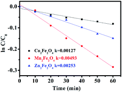 |
| | Fig. 6 First-order plots for the photocatalytic degradation of LVX using MFe2O4. | |
3.5 Activating PMS with MFe2O4 to enhance the degradation efficiency
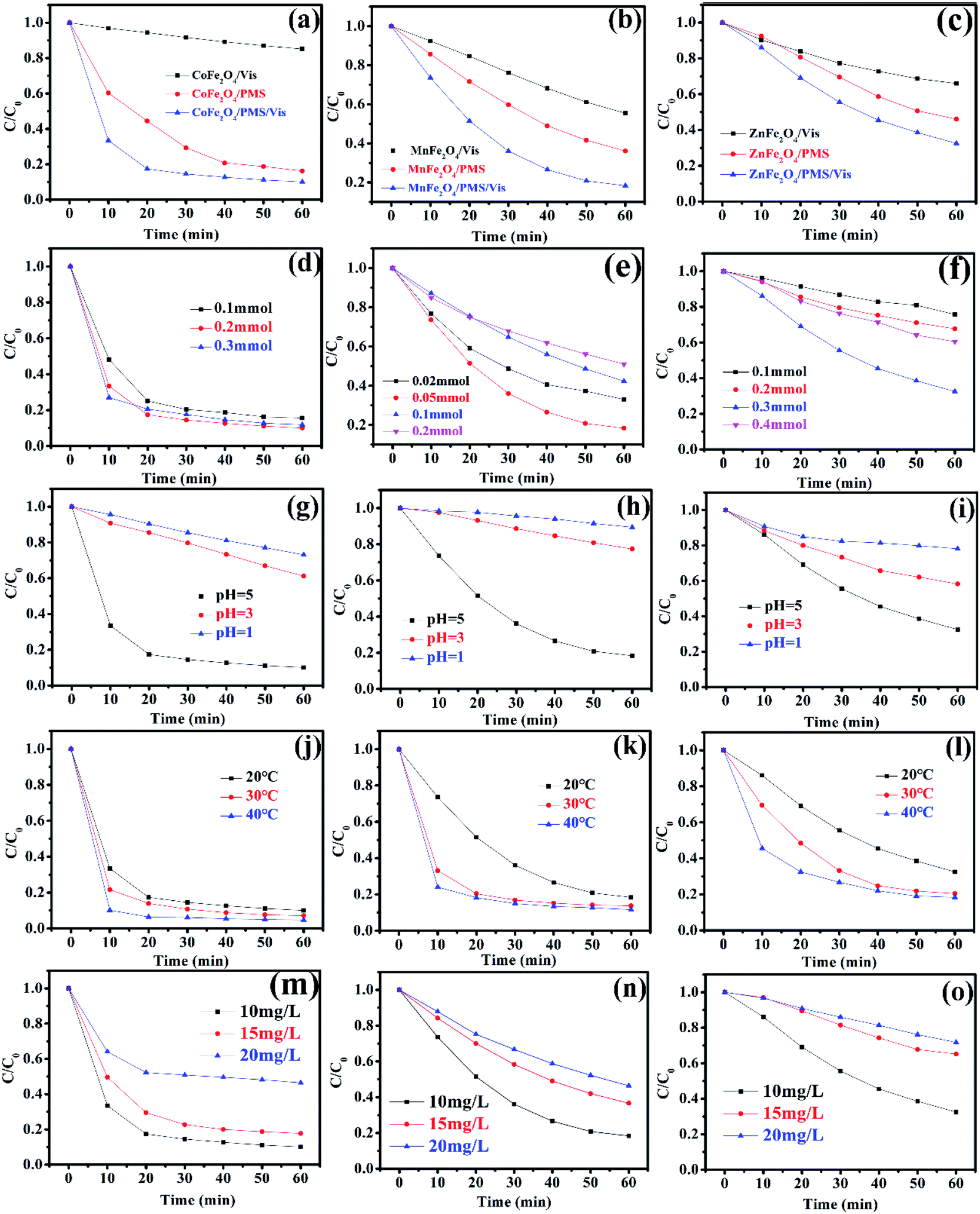
Recently, there has been increased interest by researchers regarding the advanced oxidation processes (AOPs) of the sulfate radical (SO4˙−).27,28 Because of a higher redox potential, the sulfate radical can degrade many organic pollutants.29,30 As a monopersulfate compound, PMS can be activated not only by a transition metal, but also by photogenerated e−/h+ to generate strong oxidizing sulfate radicals. Therefore, activating PMS to enhance the degradation rate with MFe2O4 under visible light irradiation might be a good choice. The degradation rate of LVX in different systems is shown in Fig. 7a–c. The photocatalytic experiments showed that the photocatalytic activity of MFe2O4 was low, and its degradation rate was the slowest of all. The degradation rate for the MFe2O4/PMS system without visible light was much slower than that of the MFe2O4/Vis/PMS system. The degradation efficiency for activation of PMS with MFe2O4 under visible light irradiation was much higher than that for PMS only activated by MFe2O4 and MFe2O4 only under visible light irradiation. The activation of PMS with MFe2O4 resulted from photogenerated e−/h+, Fe, and M, and the degradation rate was much faster than that which occurred when PMS was only activated by MFe2O4.
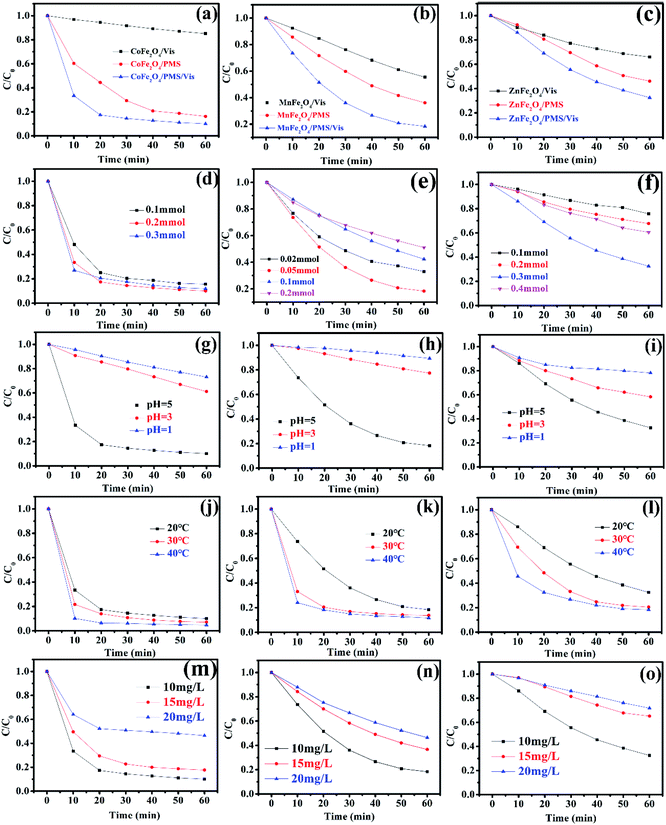 |
| | Fig. 7 The degradation rate of MFe2O4 in different systems: (a) CoFe2O4, (b) MnFe2O4, (c) ZnFe2O4 ([photocatalyst] = 0.5 g L−1, [LVX] = 10 mg L−1, [PMS] = 2 mM, 0.5 mM, and 3 mM for CoFe2O4, MnFe2O4, and ZnFe2O4, respectively); effect of PMS dosages on the degradation of LVX with PMS activated by MFe2O4 photocatalysts: (d) CoFe2O4, (e) MnFe2O4, and (f) ZnFe2O4 ([photocatalyst] = 0.5 g L−1, [LVX] = 10 mg L−1); effect of pH value on the degradation of LVX: (g) CoFe2O4, (h) MnFe2O4, and (i) ZnFe2O4 ([photocatalyst] = 0.5 g L−1, [LVX] = 10 mg L−1, [PMS] = 2 mM, 0.5 mM, and 3 mM for CoFe2O4, MnFe2O4, and ZnFe2O4, respectively); effect of temperature on the degradation of LVX: (j) CoFe2O4, (k) MnFe2O4, and (l) ZnFe2O4 ([photocatalyst] = 0.5 g L−1, [LVX] = 10 mg L−1, [PMS] = 2 mM, 0.5 mM, and 3 mM for CoFe2O4, MnFe2O4, and ZnFe2O4, respectively); effect of LVX concentrations on the degradation of LVX: (m) CoFe2O4, (n) MnFe2O4, and (o) ZnFe2O4 ([photocatalyst] = 0.5 g L−1, [PMS] = 2 mM, 0.5 mM, and 3 mM for CoFe2O4, MnFe2O4, and ZnFe2O4, respectively). | |
A comparison between this work and other photocatalyst performances for the degradation of LVX was conducted under the same conditions. As shown in Fig. S1,† the photocatalytic experiments showed that the efficiency of LVX degradation in the FeWO4/Vis/PMS and Fe2(MoO4)3/Vis/PMS systems was lower. However, the removal rate increased to 92% in an hour in the CoFe2O4/Vis/PMS system. The removal rate also reached 70–80% in an hour in the MnFe2O4/Vis/PMS and ZnFe2O4/Vis/PMS systems. This indicated that the degradation efficiency for PMS activation with MFe2O4 under visible light irradiation was much higher than that with FeWO4 or Fe2(MoO4)3.
3.5.1 Effect of PMS dosage, pH value, temperature, and LVX concentration. The effect of PMS dosage on the performance of the MFe2O4/Vis/PMS system towards LVX degradation was investigated (Fig. 7d–f). The LVX degradation rate increased with the increase in the PMS dosage in all systems, and thus, the more dosages of PMS that were added, the more SO4˙− that was produced. However, the degradation rate gradually decreased when the PMS dosage continuously increased, which was ascribed to the self-quenching effect between the sulfate radicals and PMS (eqn (1)).31,32 The experimental results indicated that the optimal dosage of PMS was 0.2 mmol, 0.05 mmol, and 0.3 mmol, respectively, for CoFe2O4, MnFe2O4, and ZnFe2O4.| | |
HSO5− + SO4˙− → SO5˙− + SO42− + H+
| (1) |
The pH value had an obvious effect on PMS activation, which was confirmed by a previous study.33 Therefore, the effect of the pH value on the degradation rate was studied. As exhibited in Fig. 7g–i, the results showed that the pH value clearly influenced the degradation efficiency. According to published literature, it was mainly attributed to the fact that H+ hindered the production of OH˙ and SO4˙−, resulting in a decrease in the number of active radicals.34 Therefore, the removal rate increased as the pH value increased.
The influence of the initial temperature on the removal of LVX by the MFe2O4 photocatalyst was further investigated. As shown in Fig. 7j–l, the degradation rate increased with increasing temperature, which was due to PMS activation in the endothermic reaction and a higher reactive oxygen species (ROS) production rate at higher temperatures, with LVX being degraded by CoFe2O4 in 10 min at 40 °C. This might be caused by the self-activation reaction of PMS under higher temperatures.32
The effects of initial LVX concentration on the degradation behaviour are shown in Fig. 7m–o. As the initial levofloxacin concentration increased from 10 mg L−1 to 20 mg L−1, the degradation kinetics decreased. This may have occurred due to the higher concentration of LVX that resulted in additional active ROS being produced.32 However, the limited photocatalysts and PMS could not produce sufficient radicals to degrade a solution with higher LVX concentration.
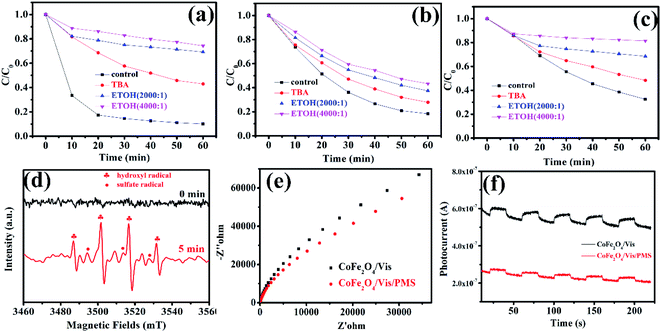
3.5.2 Degradation mechanism after PMS activation with MFe2O4. To investigate the degradation mechanism that occurs after activation of PMS with MFe2O4 and confirm the role of the active species in the degradation process, tert-butanol and ethanol were introduced as radical scavengers. Ethanol was chosen as the radical scavenger for the sulfate radical and hydroxyl radical.32 However, tert-butanol was the only effective scavenger for the hydroxyl radical.35–37 After 1 mmol tert-butanol was added to LVX solution, there was not an obvious inhibitory effect (Fig. 8a–c), which indicated that the hydroxyl radical was not the primary active specie in the MFe2O4/PMS/Vis system. Obvious inhibition of the degradation rate was observed after excess ethanol was added to the LVX solution, in which the molar ratio of ethanol and PMS was 2000![[thin space (1/6-em)]](https://www.rsc.org/images/entities/char_2009.gif) :1 (Fig. 8a–c). When the molar ratio was increased to 4000:1, the inhibition of the degradation rate was more obvious, which indicated that sulfate radical was the key active specie in the Vis/MFe2O4/PMS system.
:1 (Fig. 8a–c). When the molar ratio was increased to 4000:1, the inhibition of the degradation rate was more obvious, which indicated that sulfate radical was the key active specie in the Vis/MFe2O4/PMS system.
 |
| | Fig. 8 Effects of tert-butyl alcohol and ethanol addition on the photocatalytic degradation of LVX ([photocatalyst] = 0.5 g L−1, [LVX] = 10 mg L−1, [PMS] = 2 mM, 0.5 mM, and 3 mM for CoFe2O4, MnFe2O4, and ZnFe2O4, respectively): (a) CoFe2O4, (b) MnFe2O4, (c) ZnFe2O4; (d) EPR spectra of CoFe2O4 under visible light irradiation (DMPO as the radical trapper); (e) electrochemical impedance spectroscopy of CoFe2O4 sample electrodes with and without PMS under visible light irradiation (λ > 420 nm); (f) transient photocurrent responses of CoFe2O4 sample electrodes with and without PMS under visible light irradiation (λ > 420 nm). | |
To confirm the above results, electron paramagnetic resonance (EPR) spectroscopy was used to trace intermediate radical species that existed in the Vis/CoFe2O4/PMS system. The trapping agent 5,5-dimethylpyrrolineoxide (DMPO) was used to capture radicals ˙OH and SO5˙− in the Vis/CoFe2O4/PMS system.38,39 As shown in Fig. 8d, the characteristic peak signals of DMPO-˙OH and DMPO-SO4˙− adducts were found,40 which not only proved the coexistence of ˙OH and SO4˙− species, but also supported the sole activity of SO4˙− in this system.
Electrochemical impedance spectroscopy (EIS) was used to characterize electrochemical interfacial reactions. The photocatalytic decomposition of LVX can be explained as an electrochemical oxidation reaction in which reactants supply electrons to an anode. A smaller arc radius of the EIS Nyquist plot represents a faster electron transfer rate and a more efficient electron–hole separation.41 Fig. 8e shows the EIS response of CoFe2O4 under visible light irradiation (λ > 420 nm). The radius of the arc on the EIS Nyquist plot reflects the reaction rate occurring at the surface of the electrode. The radii tended to significantly decrease after adding PMS to the solution, indicating that both charge-transfer resistance and capacitive reactance decreased. This suggested that there was an effective separation of photogenerated electron–hole pairs and that fast interfacial charge transfer to the electron donor/electron acceptor occurred, as suggested by Leng et al.42 With the existence of PMS, the interfacial electron transfer rate and the electron–hole separation efficiency of the Vis/CoFe2O4/PMS system greatly increased.
To further confirm that PMS efficiently captured the photogenerated electrons in the Vis/CoFe2O4/PMS system, the transient photocurrent responses of CoFe2O4 were also measured under visible light irradiation. As shown in Fig. 8f, the introduction of PMS significantly decreased the density of photocurrent in the Vis/CoFe2O4/PMS system. It is likely that the photogenerated electrons were efficiently trapped by the PMS, which was consistent with results from a previous report.43
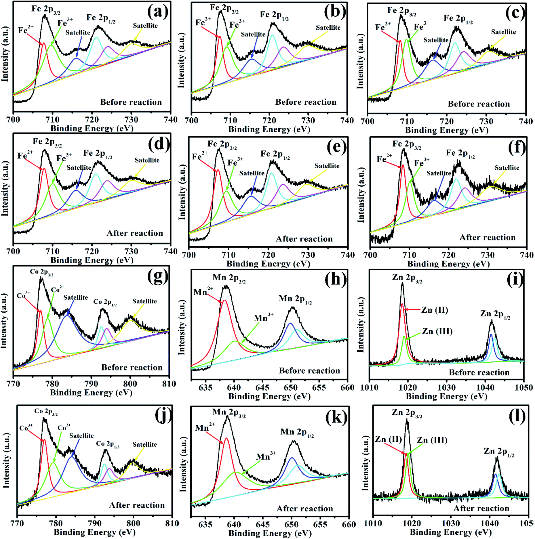
To investigate the role of iron, zinc, and manganese in Vis/MFe2O4/PMS systems, the XPS spectrum was used to analyze the samples before and after photocatalytic experiments (Fig. 9). In the XPS spectrum of CoFe2O4, the Fe 2p peaks at 707.95 eV and 721.53 eV were assigned to Fe 2p3/2 and Fe 2p1/2 (Fig. 9a and d), respectively, showing that a portion of Fe species existed in the form of Fe2+ in CoFe2O4 before the photocatalytic experiment. However, the area of Fe3+ peaks decreased, and the area of Fe2+ peaks increased after activation of PMS with CoFe2O4, which indicated that Fe3+ on the surface of CoFe2O4 was partially transformed to Fe2+.44 This proved that the regeneration of Fe(III) and a cycle of Fe(III)/Fe(II) occurred in the Vis/CoFe2O4/PMS systems.45 The Co 2p peaks at 776.93.45 and 792.98 eV were assigned to the binding energies of Co 2p3/2 and Co 2p1/2 (Fig. 9g and j), respectively, indicating that a portion of Co species existed in the form of Co3+. However, the area of the Co2+ peaks decreased, and the area of the Co3+ peaks increased after activation of PMS with CoFe2O4, which indicated that Co2+ on the surface of CoFe2O4 was partially transformed to Co3+.45 This proved that regeneration of Co(II) and a cycle of Co(II)/Co(III) occurred in the Vis/CoFe2O4/PMS systems. Similar conclusions were drawn from the XPS spectra (Fig. 9) of MnFe2O4 and ZnFe2O4 before and after activation of PMS. It proved that cycles of Fe(III)/Fe(II), Co(II)/Co(III), Mn(II)/Mn(III), and Zn(II)/Zn(III) existed in the Vis/MFe2O4/PMS systems.
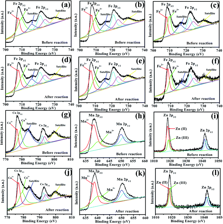 |
| | Fig. 9 (a, d, g, and j) XPS spectra of Fe 2p and Co 2p for CoFe2O4 before and after photocatalytic oxidation of LVX. (b, e, h, and k) XPS spectra of Fe 2p and Mn 2p for MnFe2O4 before and after photocatalytic oxidation of LVX. (c, f, i, and l) XPS spectra of Fe 2p and Zn 2p for ZnFe2O4 before and after photocatalytic oxidation of LVX. | |
According to the above results, the mechanism of activating PMS with MFe2O4 is shown in Scheme 1 (eqn (2)–(20)). The MFe2O4 photocatalyst absorbed visible light and then produced photogenerated e−/h+ pairs.46 PMS was activated by photogenerated electrons (e−) and then produced SO4˙− radicals. SO4˙− reacted with OH− to form OH˙ and SO42−. SO42− then reacted with h+ to form SO4˙−. The h+ also activated PMS to produce SO5˙−, and then, SO5˙− reacted with each other to generate SO4˙− (eqn (2)–(7)).47,48 PMS was also activated by iron to produce sulfate radicals. Because of the effective electron transfer from PMS to Fe(III) and Fe(II), which resulted in regeneration of Fe(III) and cycling between Fe(III) and Fe(II), enhanced degradation efficiency was achieved in activating PMS with CoFe2O4 under visible light irradiation (eqn (8)–(10)).44 Similarly, there was also regeneration of Co(II) and cycling between Co(II) and Co(III) for CoFe2O4 (eqn (11)–(13)),45 which indicated that cobalt also activates PMS to enhance the degradation efficiency, in addition to iron. MnFe2O4 and ZnFe2O4 activated PMS and regenerated in the same manner as that of CoFe2O4 (eqn (14)–(19)).44 Finally, LVX was mainly degraded by sulfate radicals and hydroxyl radicals (eqn (20)).49–51
| | |
MFe2O4 + hν → h+ + e−
| (2) |
| | |
HSO5− + e− → SO4˙− + OH−
| (3) |
| | |
SO4˙− + OH− → SO42− + ˙OH
| (4) |
| | |
HSO5− + h+ → SO5˙− + H+
| (6) |
| | |
SO5˙− + SO5˙− → 2SO4˙− + O2
| (7) |
| | |
Fe(III) + HSO5− → Fe(II) + SO5˙− + H+
| (8) |
| | |
Fe(II) + HSO5− → Fe(III) + SO4˙− + OH−
| (9) |
| | |
SO5˙− + SO5˙− → 2SO4˙− + O2
| (10) |
| | |
Co(II) + HSO5− → Co(III) + SO4˙− + OH−
| (11) |
| | |
Co(III) + HSO5− → Co(II) + SO5˙− + H+
| (12) |
| | |
SO5˙− + SO5˙− → 2SO4˙− + O2
| (13) |
| | |
Mn(II) + HSO5− → Mn(III) + SO4˙− + OH−
| (14) |
| | |
Mn(III) + HSO5− → Mn(II) + SO5˙− + H+
| (15) |
| | |
SO5˙− + SO5˙− → 2SO4˙− + O2
| (16) |
| | |
Zn(II) + HSO5− → Zn(III) + SO4˙− + OH−
| (17) |
| | |
Zn(III) + HSO5− → Zn(II) + SO5˙− + H+
| (18) |
| | |
SO5˙− + SO5˙− → 2SO4˙− + O2
| (19) |
| | |
LVX + SO4˙− + ˙OH → degradation
| (20) |
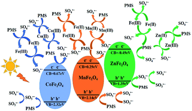 |
| | Scheme 1 Schematic drawing illustrating the mechanism of activation of PMS with MFe2O4 photocatalyst under visible light irradiation. | |
3.6 The degradation pathway of LVX
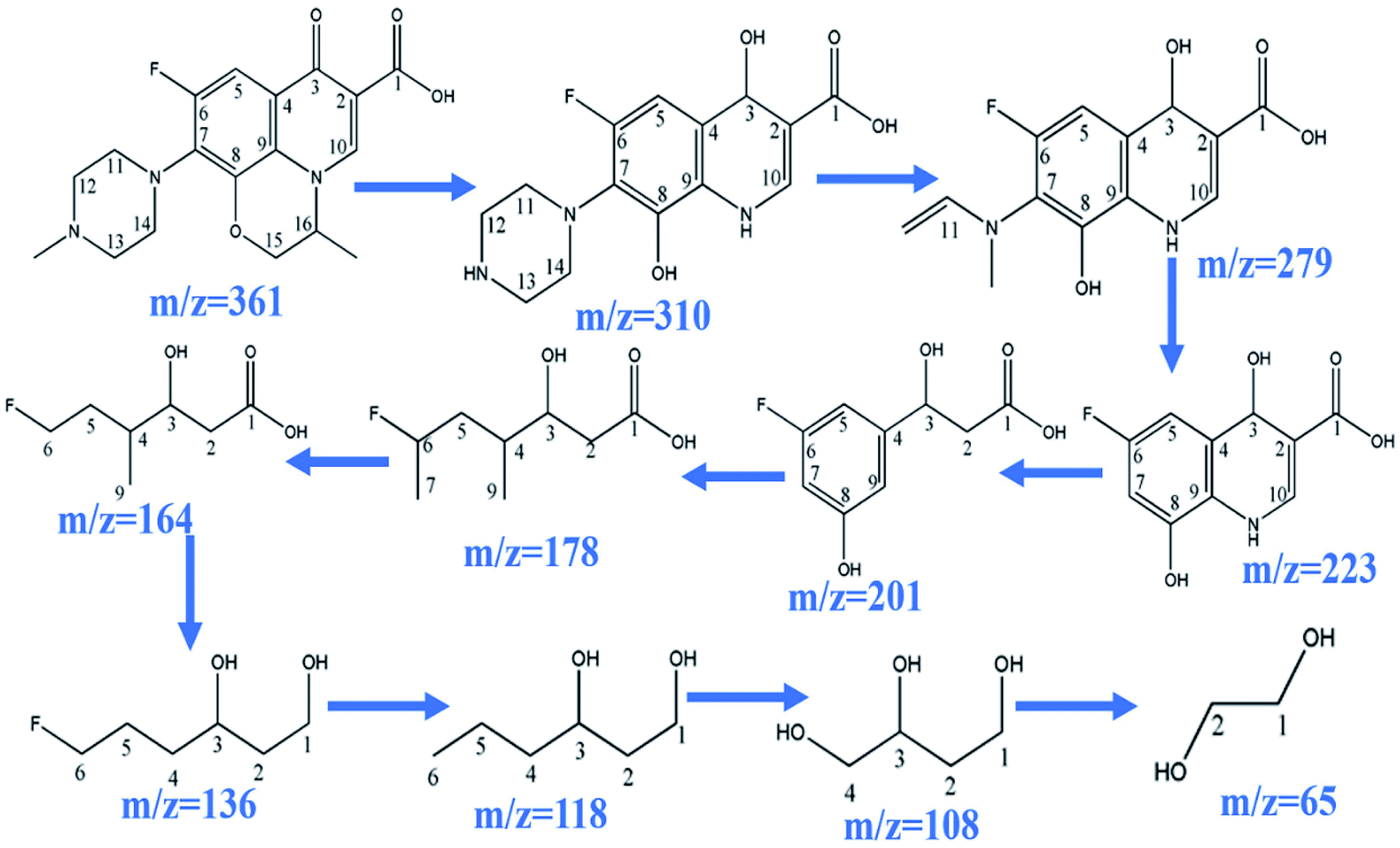
During the process of CoFe2O4 activating PMS to enhance degradation efficiency under visible light irradiation, the SO4˙− attacks LVX and then disassembles its molecular structure. The intermediate products then form, and the possible degradation pathways are shown in Scheme 2 by UPLC-MS analysis (Fig. S2†). As the weak electron donor, methyl groups facilitate the attack on LVX by electrophilic species (SO4˙−) in the demethylation process, resulting in the formation of the intermediate product of m/z = 310. With sustained degradation, the SO4˙− cleaved the ring, and the intermediate products of m/z = 279 were formed.52 With photodegradation proceeding, the nitrogen bonded with C7 was exfoliated to obtain the compound of m/z = 223. Then, the SO4˙− continued to attack the intermediate products and disconnect the ring of the intermediate structure, and the intermediate compound of m/z = 178 formed. As photodegradation proceeded, SO4˙− continued to cleave the functional groups, and glycol was formed (m/z = 65). Finally, the above intermediate products were mineralized into H2O, CO2, and others.
 |
| | Scheme 2 Possible degradation pathway of LVX. | |
3.7 Stability of MFe2O4
To study the reusability and stability of photocatalysts, recycling experiments were carried out (Fig. S3a–c†). When the degradation experiment was finished, the CoFe2O4 was filtered from the LVX solution. The CoFe2O4 was further dried at 60 °C and was used for the next degradation experiment. After three recycling experiments, there were no obvious changes in LVX degradation. Similarly, recycling experiments were conducted in Vis/MnFe2O4/PMS and Vis/ZnFe2O4/PMS systems. It was found that there was satisfactory reusability and stability for the three photocatalysts.
4 Conclusions
Nanosized MFe2O4 was successfully synthesized by a simple sol–gel method. The photocatalytic properties of MFe2O4 were investigated under visible light irradiation, and they showed decreased photocatalytic activity for the degradation of levofloxacin hydrochloride under visible light irradiation. For enhanced photocatalytic activity, MFe2O4 was used to activate peroxymonosulfate to degrade levofloxacin hydrochloride under visible light irradiation. A series of systematic experiments proved that the PMS dosage conferred an obvious effect on the degradation rate. Furthermore, there was a noteworthy effect by the levofloxacin hydrochloride concentration and the pH value on the levofloxacin hydrochloride degradation. After activation of PMS with MFe2O4, a degradation mechanism was proposed and proved by EPR, EIS, transient photocurrent, and XPS. Kinetic studies using radical scavenger technologies suggested that sulfate radical controls the degradation process.
Author contributions
Di Li: project administration, Mingyang Long: investigation, Hongmiao Li: data curation, Xinguo Ma: methodology, Qianqian Zhao: formal analysis, and Qi Wen: writing – review and editing.
Conflicts of interest
There are no conflicts to declare.
Acknowledgements
This work was supported by the National Natural Science Foundation of China (21301135) and Xi′an University of Architecture and Technology Science Foundation (ZR21068). We thank Ms Fang Song at the Instrument Analysis Center of Xi'an University of Architecture and Technology for her assistance with the SEM analysis, and also thank Eceshi (https://www.eceshi.com) for the EPR and photo-electrochemical measurements.
Notes and references
- F. Wang, Z. Chen, Z. Zhu and J. Guo, J. Mater. Res. Technol., 2022, 17, 1696–1706 CrossRef CAS.
- S. Liu, X. Jiang, G. I. N. Waterhouse, Z.-M. Zhang and L.-m. Yu, Sep. Purif. Technol., 2022, 294, 121094 CrossRef CAS.
- S. Altaf, R. Zafar, W. Q. Zaman, S. Ahmad, K. Yaqoob, A. Syed, A. J. Khan, M. Bilal and M. Arshad, Ecotoxicol. Environ. Saf., 2021, 226, 112826 CrossRef CAS PubMed.
- J. Xu, M. Zhang, X. Li and M. Chen, J. Environ. Chem. Eng., 2022, 10, 107484 CrossRef CAS.
- M. R. Abukhadra, A. A. AlHammadi, J. Seong Khim, J. S. Ajarem and A. A. Allam, J. Cleaner Prod., 2022, 356, 131836 CrossRef CAS.
- J. Liang, Y. Hou, H. Zhu, J. Xiong, W. Huang, Z. Yu and S. Wang, Chem. Eng. J., 2022, 433, 133574 CrossRef CAS.
- L. A. Goulart, A. Moratalla, P. Cañizares, M. R. V. Lanza, C. Sáez and M. A. Rodrigo, J. Environ. Chem. Eng., 2022, 10, 107317 CrossRef CAS.
- R. Nawaz, C. F. Kait, H. Y. Chia, M. H. Isa, L. W. Huei, N. T. Sahrin and N. Khan, Environ. Technol. Innovation, 2021, 23, 101764 CrossRef CAS.
- Y.-W. Li and W.-L. Ma, Chemosphere, 2021, 280, 130667 CrossRef CAS PubMed.
- S. Jian, Z. Tian, J. Hu, K. Zhang, L. Zhang, G. Duan, W. Yang and S. Jiang, Adv. Powder Technol. Mater., 2022, 1, 100004 CrossRef.
- Y. Yao, Y. Cai, F. Lu, F. Wei, X. Wang and S. Wang, J. Hazard. Mater., 2014, 270, 61–70 CrossRef CAS PubMed.
- A. Manohar, V. Vijayakanth, S. V. P. Vattikuti and K. H. Kim, Mater. Chem. Phys., 2022, 286, 126117 CrossRef CAS.
- Y. Lu, M. Yousaf, M. N. Akhtar, A. Noor, M. Akbar, M. A. K. Y. Shah, S. Yan and F. Wang, Ceram. Int., 2022, 48, 2782–2792 CrossRef CAS.
- H. D. Abdul kader, I. S. Mohammed and S. H. Ammar, Environ. Nanotechnol., Monit. Manage., 2022, 17, 100664 Search PubMed.
- H. B. Desai, L. J. Hathiya, H. H. Joshi and A. R. Tanna, Mater. Today: Proc., 2020, 21, 1905–1910 CAS.
- M. M. Sabzehmeidani, H. Karimi, M. Ghaedi and V. M. Avargani, Mater. Res. Bull., 2021, 143, 111449 CrossRef CAS.
- J. Wang, J. Li, X. Li, X. Bao and X. Gao, J. Magn. Magn. Mater., 2018, 462, 53–57 CrossRef CAS.
- O. Mounkachi, R. Lamouri, E. Salmani, M. Hamedoun, A. Benyoussef and H. Ez-Zahraouy, J. Magn. Magn. Mater., 2021, 533, 168016 CrossRef CAS.
- X. Zhang, C. Li, T. Chen, Y. Tan, X. Liu, F. Yuan, S. Zheng and Z. Sun, Int. J. Min. Sci. Technol., 2021, 31, 1169–1179 CrossRef CAS.
- Y. Ma, X. Xu, L. Lu, K. Meng, Y. Wu, J. Chen, J. Miao and Y. Jiang, Ceram. Int., 2021, 47, 34005–34011 CrossRef CAS.
- M. H. Habibi and H. J. Parhizkar, Spectrochim. Acta, Part A, 2014, 127, 102–106 CrossRef CAS PubMed.
- A. Allabar and M. Nowak, Chem. Geol., 2020, 556, 119833 CrossRef CAS.
- N. Akhlaghi and G. Najafpour-Darzi, J. Mol. Catal., 2022, 519, 112118 CrossRef CAS.
- C. Akshhayya, M. K. Okla, W. H. Al-Qahtani, M. R. Rajeshwari, A. Mohebaldin, Y. A. Alwasel, W. Soufan, M. A. Abdel-Maksoud, H. AbdElgawad, L. L. Raju, A. M. Thomas and S. S. Khan, J. Environ. Chem. Eng., 2022, 10, 107673 CrossRef CAS.
- Y. Ma, J. Du, Y. Fang and X. Wang, ChemSusChem, 2021, 14, 946–951 CrossRef CAS PubMed.
- A. Kudo, I. Tsuji and H. Kato, Chem. Commun., 2002, 1958–1959 RSC.
- W. S. Chen and C. P. Huang, Chemosphere, 2015, 125, 175–181 CrossRef CAS PubMed.
- J. Zou, J. Ma, L. W. Chen, X. C. Li, Y. H. Guan, P. C. Xie and C. Pan, Environ. Sci. Technol., 2013, 47, 11685–11691 CrossRef CAS PubMed.
- M. M. Ahmed, S. Barbati, P. Doumenq and S. Chiron, Chem. Eng. J., 2012, 197, 440–447 CrossRef.
- M. G. Antoniou, A. A. de la Cruz and D. D. Dionysiou, Environ. Sci. Technol., 2010, 44, 7238–7244 CrossRef CAS PubMed.
- C. Brandt and R. Vaneldik, Chem. Rev., 1995, 95, 119–190 CrossRef CAS.
- J. Kang, H. Zhang, X. Duan, H. Sun, X. Tan, S. Liu and S. Wang, Chem. Eng. J., 2019, 362, 251–261 CrossRef CAS.
- R. Li, H. Hu, Y. Ma, X. Liu, L. Zhang, S. Zhou, B. Deng, H. Lin and H. Zhang, J. Cleaner Prod., 2020, 276, 124246 CrossRef CAS.
- Y. Huang, L. Nengzi, X. Zhang, J. Gou, Y. Gao, G. Zhu, Q. Cheng and X. Cheng, Chem. Eng. J., 2020, 388, 124274 CrossRef CAS.
- X. L. Wu, X. G. Gu, S. G. Lu, Z. F. Qiu, Q. Sui, X. K. Zang, Z. W. Miao and M. H. Xu, Sep. Purif. Technol., 2015, 147, 186–193 CrossRef CAS.
- G. V. Buxton, C. L. Greenstock, W. P. Helman, A. B. Ross and W. Tsang, J. Phys. Chem. Ref. Data, 1988, 17, 513–886 CrossRef CAS.
- Y. Liu, H. Guo, Y. Zhang, W. Tang, X. Cheng and H. Liu, Chem. Phys. Lett., 2016, 653, 101–107 CrossRef CAS.
- H. Fu, C. Pan, W. Yao and Y. Zhu, J. Phys. Chem. B, 2005, 109, 22432–22439 CrossRef CAS PubMed.
- Y. Wang, L. Zhou, X. Duan, H. Sun, E. L. Tin, W. Jin and S. Wang, Cataly. Today, 2015, 258, 576–584 CrossRef CAS.
- H. Sun, G. Zhou, Y. Wang, A. Suvorova and S. Wang, ACS Appl. Mater.
Interfaces, 2014, 6, 16745–16754 CrossRef CAS PubMed.
- X. Li, X. Chen, Y. Fang, W. Lin, Y. Hou, M. Anpo, X. Fu and X. Wang, Chem. Sci., 2022, 13, 7541–7551 RSC.
- W. H. Leng, Z. Zhang, J. Q. Zhang and C. N. Cao, J. Phys. Chem. B, 2005, 109, 15008–15023 CrossRef CAS PubMed.
- Y. Gao, Z. Zhang, S. Li, J. Liu, L. Yao, Y. Li and H. Zhang, Appl. Catal., B, 2016, 185, 22–30 CrossRef CAS.
- C. Tan, N. Gao, D. Fu, J. Deng and L. Deng, Sep. Purif. Technol., 2017, 175, 47–57 CrossRef CAS.
- Y. Ren, L. Lin, J. Ma, J. Yang, J. Feng and Z. Fan, Appl. Catal., B, 2015, 165, 572–578 CrossRef CAS.
- Y. Fang, Y. Hou, X. Fu and X. Wang, Chem. Rev., 2022, 122, 4204–4256 CrossRef CAS PubMed.
- Z. Shen, H. Zhou, Z. Pan, Y. Guo, Y. Yuan, G. Yao and B. Lai, J. Hazard. Mater., 2020, 400, 123187 CrossRef CAS PubMed.
- H. Shao, X. Zhao, Y. Wang, R. Mao, Y. Wang, M. Qiao, S. Zhao and Y. Zhu, Appl. Catal., B, 2017, 218, 810–818 CrossRef CAS.
- H. Huang, T. Guo, K. Wang, Y. Li and G. Zhang, Sci. Total Environ., 2021, 758, 143957 CrossRef CAS PubMed.
- T. Guo, L. Jiang, K. Wang, Y. Li, H. Huang, X. Wu and G. Zhang, Appl. Catal., B, 2021, 286, 119883 CrossRef CAS.
- T. Guo, L. Jiang, H. Huang, Y. Li, X. Wu and G. Zhang, J. Hazard. Mater., 2021, 416, 125838 CrossRef CAS PubMed.
- Z. Zhang, Z. Pan, Y. Guo, P. K. Wong, X. Zhou and R. Bai, Appl. Catal., B, 2020, 261, 118212 CrossRef CAS.
|
| This journal is © The Royal Society of Chemistry 2022 |
Click here to see how this site uses Cookies. View our privacy policy here. 
 Open Access Article
 This Open Access Article is licensed under a Creative Commons Attribution-Non Commercial 3.0 Unported Licence
 *a,
Hongmiao Lia,
Xinguo Ma
*a,
Hongmiao Lia,
Xinguo Ma